1
Technical Specifications
Amplifiers
Dual, MOSFET H-bridge, 3 state, pulse width modulated switching
at 20 kHz. 0.5 - 5.5 amps/phase output current, switch
selectable in 0.2 increments. Overcurrent and overtemperature
protection. Automatic idle current reduction (defeatable), reduces
current to 50% of setting after one second. Minimum motor
inductance is 0.8 mH.
Power Supply Linear, toroidal transformer based for high reliability and low
noise. 110 or 220 VAC input, switch selectable. 50-60 Hz.
DC voltage at nominal line voltage: 75 VDC full load, 90 VDC no
load.
Inputs
Speed, Enable: optically isolated, differential 5-24V logic. 2200
ohms internal resistor.
Getting Started
To use your Applied Motion Products motor control, you will need:
✔ a power cable (line cord)
✔ a compatible step motor (see page 21)
✔ a small flat blade screwdriver for tightening the connectors - an Applied Motion
Products screwdriver suitable for this purpose is included with your drive.
For pulse & direction mode:
✔ a source of step pulses (usually an indexer is used)
For oscillator mode:
✔ an instrument for measuring motor speed (tachometer, freq. counter or o-scope)
For joystick mode:
✔ An analog joystick
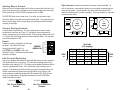
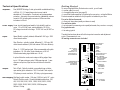
The sketch below shows where to find the important connection and adjustment
points. Please examine it now.
All mating connectors are included.
Step, Direction: optically isolated, differential 5 - 12V logic, 680
ohms internal resistance. (24V with external 1000 ohm resistors)
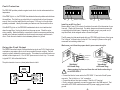
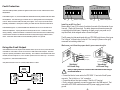
I/O connector
SPEED
TACH OUT
EXTERNAL POT
/JOYSTICK/0-5V
ANALOG SPEED
POWER
TEMP
SHORT
JOYSTICK
EXT SPEED
50% IDLE
CURRENT
(BASE = 0.5 A)
Tach & Fault: Optically isolated, uncommitted (open collector,
open emitter) photo transistors. 30V, 20 mA max. Tach output is
100 pulses per motor revolution, 50% duty cycle (square wave).
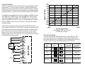
Microstepping Oscillator/joystick modes: 1/64 step (12,800 s/r) with 1.8° motor.
Pulse & Direction mode: 16 switch selectable resolutions: 200,
400, 1000, 2000, 5000, 10000, 12800, 18000, 20000, 21600,
25000, 25400, 25600, 36000, 50000, 50800 steps/rev.
Self test: 1/2 step.
-22-
HIGH SPEED
LOW SPEED
ACCEL
potentiometers
OSC BYPASS
SELF TEST
ACCEL/DECEL RATE
LOW SPEED
HIGH SPEED
LEDs
POWER
OVER TEMP FAULT
MOTOR SHORT
switches
STEPS/REV
MOTOR CURRENT
IDLE CURRENT
EXT/INT POT
JOYSTICK MODE
switches
MOTOR
90V pk
B–
B+
A–
A+
PDO 5580
Step Motor Driver
AC
POWER
Outputs
0.2
0.4
0.8
1.6
2.0
1 2 3 4 5 6
In pulse & direction mode, motor steps on falling edge of step
input. 0.25 µsec minimum pulse, 2 MHz max step rate. 1 µsec
minimum set up time, 50µs minimum hold time for direction
signal.
DIRECTION
STEP
ENABLE
FAULT
1 2 3 4 5 6 7 8
Wiper: 0 - 5 VDC analog signal. Max recommended pot/joystick
impedance: 1K - 5K ohms. Joystick dead zone: ± 80 mV.
Potentiometer/analog signal dead zone: 40 mV.
I/O connector
DIR+
DIR–
STEP+
STEP–
EN+
EN–
FAULT+
FAULT–
SPEED+
SPEEDTACH+
TACH–
CW
WPR
CCW
STEPS/REV
OSC MODE
SELF TEST
connector
MOTOR
G
connector
N
AC POWER
L
-3-