1
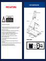
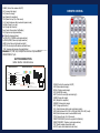
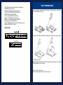
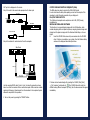
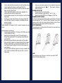
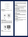
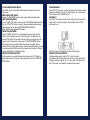
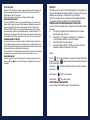
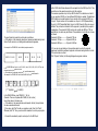
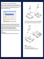
GENEE TECHNOLOGIES
INDIA PRIVATE LIMITED
An ISO 9001:2008 certified company
®
Classroom for the Future
8100
®
8100
Tel: 0124-4934500
@ Email: [email protected]
Website: www.genee-india.com, www.geneeworld.com
WWW
Plot No. 698, Udyog Vihar, Phase V, Gurgaon, Haryana-122016, India
Fax: 0124-4934521
User manual
PRECAUTIONS
PRECAUTIONS
NOT
THIS
WAY
Please
follow
these precautions:
SPECIFICATIONS
To prevent fire or shock hazard, do not expose the unit to rain or moisture.
To Colour
prevent electrical
the cabinet. Refer to qualified
PALopen
system
system shock, do not
personnel for service only.
professional
CCDwith camera
DoPickup
not use device
the unit continuously1/4”
for more
than 24 hours
auto focus on. It may cause damage to the camera lens.
Be Resolution
careful not to spill water or other
onto the SVGA
unit, or(800x600)
allow
XGA liquids
(1024x768),
combustible or metallic objects to get inside the cabinet.
Totalthe
Pixels
470,000
Unplug
visualiser from the wall
outlet when it is not being
RGB
pixels
used
for Output
a long period
of time. 780,000
Clean the cabinet with a soft cloth
moistened
mild zoom
22xlightly
optical
zoom,with
10xadigital
Lens
detergent solution.
Focus/Iris
Clean
the lens carefully with an Auto/manual
air spray or softselectable
dry cloth to avoid
scratching
it.
Auto
White balance
When the lamps flash or become dark, they should be replaced with new ones.
Yes
Image split
Avoid switching arm lights and back light frequently.
Negative/positive
Remove
the camera lens cap before power the unit on.
conversion
Black/white and
colour selection
Image freeze
Mirror
Lights
Input connections
PARTS IDENTIFICATION
PARTS IDENTIFICATION
Audio: Mini jack 2
MIC: Mini jack 1
PC Audio: Mini jack 2
RGB: DB15FLC2
RGB: DB15FLC2
C-Video: RCA jack 1
Output connectors
S-Video: 4 pin mini Din 1
Audio: Mini jack 1
Operating System
Window 2000/XP
USB connector
30 frames/sec
RS-232 connector
9-pin, D-Sub, male/6-pin PS/2
USB port
USB 2.0
12V/4A
external AC adaptor
Power requirements
Folded: 20.0”x16.1”x4.7”
Dimensions (WxDxH) Setup: 20.0”x20.9”x22.4”
Packing: 25.6”x21.3”x9.1”
N.W: 5.5g (12.1lbs
CONTROL
Weight PANEL
G.W: 9.5g (20.9lbs)
Mir
Yes
Ppw
Yes
Yes
Yes
Arm light: 1.5W LED lamps x 2
Back light: 4 W LED lamps
C-Video: RCA jack 1
S-Video: 4 pin mini Din 1
Frz
Neg
Far
Accessory
Pin
Title
AC powerCCD/PC1/PC2
cord
VIDEO
RGB cable
Audio/Video cable
+
Computer RS232 cable (9-pin
to W
9-pin)
T
POWER
Projector RS232
cable
LAMP
AUTO(6-pin to 9-pin)
USB cable
Audio convert cable
AC adaptor
User’s manual
Software CD
Infrared remote control
Warranty card
POWER (Control the visualiser On/Off)
Mir (V-reverse the image)
Frz (Freeze the image)
Neg (Display film negatives)
disconnect
thethe
projector
thescreen)
RS232 port first) and select the Baud Rate and
Title (Freeze
top 1/8from
of the
Parity
based
on
the
projector’s
Baud
Rate,
then click
the “TEST” button to pop up the
D./S. (Switch between static mode and
dynamic
mode)
Projector
Code
Test
dialogue
box,
input
the
Baud
Rate
and Parity based on the
Far/Near (Focus far or near)
projector’s
Baud
rate,
then
click
“Open”.
Split (Image Split function)
Ppw (Control the projector On/Standby)
Pin (Projector input signal selection)
/ (Move the image up/down)
CCD/PC1/PC2 (CCD/RGB input signal selection)
S-VIDEO /VIDEO (Video input signal selection)
LAMP (Control the arm lights and back light)
AUTO (To auto adjust white balance and auto focus)
T/W (Increase and decrease the magnification)
Remarks:
Frz,Frz,
Title,
D./S.D./S.
and and
Split Split
functions
are only
on PROJECTOR
OUT port.
Remarks:
Title,
functions
areavailable
only available
on
REMOTE CONTROL
REMOTE CONTROL
2. Rotate the camera head clockwise until the camera head is parallel to the
camera stand, carefully Fold the camera stand down to the front panel.
PROJECTOR OUT port.
BUTTON INSTRUCTION
Button function instruction
sheet INSTRUCTION
BUTTON
Click the projector control buttons on the visualiser’s operating panel to check if
Button function instruction shee
the control code that the program received is the same as the sending code. If
the receivingButton
code Instruction
is same to the sending
code,Instruction
the input codes
are correct.
If the
Indicator
Fold/Setup
Instruction
visualiser can not control the projector, please do the following.
1. Check to
see
control codes
of projector
are correct.
Freeze
Image if the source
Negative/Positive
CCD /PC1/ PC2
S-V ideo/V ide o
2. Check toMirrormake
sure theFreezconnection
e the Top 1/8 of the Screen between the visualiser and the projector is
Im age
correct.Dynamic/S tatic Mode
Move Image Up
FOLDING THE
UNIT
Move Image Down
S plit Screen
POWER
Aut o Ad just Color
Projector
Power arm lightProjector
1. Fold the
right
down
first
onto
the base, then
the left arm down.
Input Selec
t
Brightn ess and Focus
On/Standby
Mir
Fr z
Neg
D./S.
Far
Near
Split
Ppw
Pin
Title
Focus Adjustment
Press and H old Two S econds
to P ower Off Vis ualize r
Light Control
(Side Light s/ B ack Light /Light s Of f)
POWER (Control the visualiser On/Off)
SAVE (Save captured images)
RECALL (Display saved images)
EXIT (Exit RECALL mode)
LAMP (Control the arm lights and back light)
FREEZE (Freeze the image)
NEG (Display film negatives)
Cautions:
MIRROR
(V-Reverse the image)
a. (Image
Don’t lay
thefunction)
unit down flat.
SPLIT
split
b.
Don’t
try
to
stand
it onmode
its rear
sides. mode)
D./S. (Switch between static
andordynamic
c.
Don’t
try
to
pick
up
this
unit
by
pulling
the camera
XGA (Switch between XGA (1024 x 768) and SVGA
(800 xstand.
600) mode)
B&W (Switch between colour mode and B&W mode)
TITLE (Freeze the top 1/8 of the screen)
PROJECTOR POWER (Control the projector On/Standby)
PROJECTOR INPUT (Projector input signal selection)
TEXT (Switch between image/text mode)
AUTO (To auto white balance and auto focus)
TELE/ WIDE (Increase and decrease the magnification)
FAR/NEAR (Focus near or far)
VOL+/VOL- (Increase or decrease the volume)
CCD/PC1/PC2 (CCD/RGB input signal selection)
VIDEO (Video input signal selection)
RED +/- (Increase/decrease the red hue)
BLUE +/- (Increase/decrease the blue hue)
BRIGHT +/- (Increase/decrease the brightness)
SCROLL / (Move the image up/down)
Remarks: FREEZE, TITLE, D./S. and SPLIT functions are only
available on PROJECTOR OUT port.
The input
format of projector’s control code is as follows:
CONNECTIONS
a. If the data is in the numerical value format, please input data directly, block
them off with comma, do not distinguish lowercase and uppercase.
7
manual is :
projector
8
For example: the “POWER ON” code in Hitachi
OUT
OUT
AUDIO VIDEO
IN
S-VIDEO
IN
AUDIO VIDEO
AUDIO
S-VIDEO AUDIO IN
BA D2
BE EF 03 06 00
PROJECTOR
OUT -COMPUTER- IN
00 60
01 00
Side Panel
OUT-12V- IN
BASIC PREPARATIONS
with a RS232 cable Please disconnect the computer from the RS232 port first. Then
BASICon
PREPARATIONS
use buttons
the operation panel to control the projector.
1.
Use
one
hand toa hold
base of
the visualiser,
use cable
the other
to carefully lift
The visualiser provides
6-pinthe
to 9-pin
RS232
cable. If this
doeshand
not match
up
the
camera
stand
of
the
unit.
to your projector’s RS232 port, an additional RS232 cable is needed. This additional
RS232 cable can be made based on the pin location of the projector’s RS232 control port. The pin locations of the visualiser are: the pin 1 is RXD (Received Data);
the pin 5 is TXD (Transmitted Data); the pin 4 is GND (Ground). Other pins are not
defined. The pin location information of the projector is provided by the projector’s
manufacturer. The projector’s RS232 control port normally has RXD pin, TXD pin
and GND pin, the name may be different. The parallelism of each data pin is shown
as follows:
5
6
Visualiser’s RXD pin------------Projector’s TXD pin
4
3
Visualiser’s TXD pin------------Projector’s RXD pin
21
Visualiser’s GND pin------------Projector’s GND pin
5. If you can not use buttons on the operation panel to control the projector,
please use Code-Writing software’s projector control code testing function to check
Open code
the arm
lights and rotate the camera head until they are in proper positions.
if the 2.
control
is correct.
Click “Projector” button, the following dialogue box appears as below:
01 00
18
PROJECTOR MIC
USB
RGB IN
AUDIO IN
RS232
In the POWER ON box, Input : be, ef, 03, 06, 00, ba, d2, 01, 00, 00, 60, 01, 00. Then use
the same input rule to input other code.
b. If the data is in the character string format, input ‘character string’.
For example: the “POWER ON” code in the SHARP C40/50 projector manual is :
P
O
(“-“ is space
W
E
-
-
-
1
is enter.)
In the POWER ON box, input ’POWER 1’, 0d, 0a
(Remarks: There are 3 spaces after POWER, 0d, 0a is enter.)
Input other codes in the same way.
c. If the data is in the numerical value and character format, then synthesize
the above-mentioned formats.
3) Once done, click “Add” to add your projector model, then Click “Send”.
Afterward, click “Ok”. Now, you can use the visualiser to control your projector.
4. Connect the visualiser’s projector control port to the RS232 port
3. Making
connections:
Connect
the visualiser
to a computer with a RS232 cable (Please
Before making any connection, turn off all the power, including power of the visualiser
and the equipment to be connected.
Step 1: Connect power source.
First connect the power cord to the 12V IN connector.
Step
2: Connect
toathe
projector.
computer
connected
with
USB
connector.
Click [Start] -> [Program] -> [VideoCap] -> “VideoCapx.xx” (x.xx is software’s version)
Rear Panel
to open the software.
A. Static Images Snap
Click “Capture”—>“Capture Frame”, input the file name in dialogue box, or you can click
icon on the toolbar, then input file name in dialogue window. The image file is
JPG
OUT
OUT
AUDIO VIDEO
S-VIDEO
IN
AUDIO VIDEO
IN
AUDIO
S-VIDEO AUDIO IN
PROJECTOR
OUT -COMPUTER- IN
OUT-12V- IN
2.Step
Connect
the RS232
cable to computer.
the computer’s connector. The visualiser’s RS232 port is
3: Connect
to a desktop
located on its right side.
3. After completion of the connection, turn on the visualiser
click [start] -> [All Programs] -> Visualiser -> and the following dialogue box appears
Rear Panel
as below:
To the
OUT
OUT
AUDIO VIDEO
S-VIDEO
IN
AUDIO VIDEO
Monitor
IN
AUDIO
S-VIDEO AUDIO IN
PROJECTOR
OUT -COMPUTER- IN
OUT-12V- IN
USB Connector
RGB Output
format.
B. Snap Video Stream
Click “Capture”—> “Start Capture”, input the file name in dialogue box, or click
icon on the toolbar, then input the file name in dialogue box. If you want to set the
Side Panel
time limit for the capture, select “Capture” ->“Set
Time Limit” to set the time limit. Click
“Start Capture” to start capture, and click “Stop Capture” or “
” icon on the toolbar to
stop
RS232
Cable
RGB Input
RS232 Cable
Computer
Screen
Projector
PROJECTOR MIC
USB
RGB IN
AUDIO IN
PROJECTOR MIC
USB
RGB IN
AUDIO IN
RS232
Side Panel
RS232
capture. (If you have set the time limit, it will stop automatically when the time is up.)
Connect
The video
file is visualiser’s
AVI format.PROJECTOR port to the RGB IN port of the projector
portFrame
with the
C. Set the
RateRGB cable provided together the visualiser.
If you need
control
a projector
with
theopen
visualiser,
please
useRate”
the projector
Click [Capture]
-> [Set
Frame
Rate], and
click
“Choose
Frame
to set the
RS232 cable (6-pin to 9-pin) to make the connection between the projector
frame rate.
and the
visualiser. Some projector models may require a converter cable in
D. Set Time
Limit
addition ->
to this
RS232
cable
connect
to thecapturing
projectorvideo.
Click [Capture]
[Set standard
Time Limit]
to set
the to
time
limit while
control port,
for the pin locations
and shape of some projectors’ control
CONTROLLING
PROJECTOR
WITH VISUALISER
port
connector
mayisbeused
different
from the
connector
of a standard
RS232
The code
writing
software
to inputting
projector’s
control
code, then
can control
After
thethe
visualiser
is connected to the projector, you can control
various cable.
projector
with
visualiser.
projector’s
power to
on,the
standby
andwith
inputthe
selection
with the visualiser.cables.
(For
1. Connect
the visualiser
projector
RGB、VIDEO、S-VIDEO
projectors other than Hitachi, the Code Writing program that comes with
the visualiser is required for this function.)
Note: You can connect a laptop computer to the RGB IN port of side panel with a
RGB cable.
S-Video Cable
When the indicator of “Current RS-232 Connection Status” is green, that means the
S-Video out
connection between
the visualiser and the computer’s RS232 connector is good. If the
Audio out
indicator is red, Video
please
check
if the RS232 cable is connected correctly. When all the
equipment
Rear Panel
cables are connected correctly, please click “Projector” to select
your projector model
under the drop-down list, then click “Send”. If you can not find your particular projector
model in the “Projector”, please do the following:
Projector
amplifier/speaker
equipment)
1) (or
Select
“Baud
rate” and “parity” and input the projector control code. (The baud
rate, parity andAudio
control
code is supplied by projector’s manufacturer, please refer to the
input
projector’ manual)
OUT
AUDIO
IN
IN
OUT
VIDEO
S-VIDEO
AUDIO
VIDEO
AUDIO
S-VIDEO
AUDIO IN
PROJECTOR
OUT
-COMPUTER-
IN
OUT-12V- IN
Step 4: Connect video equipment with S-Video input.
Output of the S-Video signal from the visualiser to the projector is already done
in the step 2, where the RGB cable comes out from the visualiser and goes to the
projector. After the connections as steps 2, 3, 4 are made, input signals from the
computer, visualiser CCD and S-Video are going to the RGB1 input on the projector
and will be displayed on the projector screen as RGB1. These signals can be seen in
turn when pressing “CCD/PC1/PC2” and “S-VIDEO/VIDEO” on the control panel of
the visualiser.
Remarks: RGB IN signal can not go to S-VIDEO OUT or VIDEO
OUT
port
to be displayed on the screen.
TITLE
FUNCTION
Step
Connect
the second
video
input.the upper 1/8
Press5:the
“Title” to
button
once and
theequipment
image splitwith
intovideo
two parts,
part of the image will freeze
and
Video
Cable stay on top 1/8 of the screen. Press “Title”
button again to exit the Title mode.
Note:
This function is not available on S-Video and Video output.
Video out
IMAGE SAVE Audio
AND
RECALL
out
Press Video
theequipment
“SAVE” button once to save one captured image, it can save up to 7
Rear Panel
images. After 7 images are saved, the 8th image will replace the previous 1st
image and will become the new 1st saved image. (On the remote control)
Press the “RECALL” button once to display the saved images, then press the
Projector Color
numerical button
to monitor
show the corresponding image. For example: Press “2” to
display the second image. At this status, the function under each numeric key is
Video
in
not available. Press “RECALL”
again
to exit this mode. (On the remote control)
INFRARED REMOTE CONTROL
Step
6: Connections
for external
control
from
the different
computer.
The remote
control can
control the
camera
from
angels. Please note
that an infrared remote control can only be used up to a certain distance from
the unit. Objects situatedSide
between
the visualiser and the infrared remote control
Panel
and a weak battery may interfere with the reception.
On the left side of the visualiser stage, there is a built-in remote control storage
compartment where you can store the remote control when not in use.
IMAGE SCROLLING
Press the “ ” button to scroll the image down to display the upper part of the
image. Press the “ ” button to scroll the image up to display the lower part of
the image.
OUT
AUDIO
PROJECTOR MIC
USB
RGB IN
AUDIO IN
IN
OUT
VIDEO
S-VIDEO
AUDIO
IN
VIDEO
AUDIO
S-VIDEO
AUDIO IN
PROJECTOR
OUT
-COMPUTER-
IN
OUT-12V- IN
RS232
RS-232 cable
USB cable
OUTPUT
MODE AND VERTICAL FREQUENCY (60Hz)
USB
PORT
canbe
output
signal
in thestill
SVGA
/XGA from
format.
The RGB
USB output
port can
usedato
transfer
images
the visualiser to a
In order to No
achieve
the best
picture quality
you must
set the outputs
the the
computer.
additional
computer
hardware
is required.
In this of
way,
visualiser
to
match
the
native
resolution
of
your
display
unit.
visualiser can be used as a 3-D scanner for your computer.
PAL/NTSC VIDEO OUTPUTS
Connect the visualiser to your computer with the supplied USB cable.
The S-Video and composite video outputs are set to PAL (NTSC) during
The
visualiser software is available on the supplied CD-ROM.
manufacturing.
CONTROLLING
THE VISUALISER
FROM A COMPUTER
INSTALLING VISUALISER
SOFTWARE
You
can
control
the
visualiser
from
a
computer
withwhich
a RS232
This function is to snap and display images with the connected
USB interface,
connector.
includes displaying static and dynamic pictures, snapping dynamic images and
A.
Connect
the computer
with the
computer
playing back
the dynamic
imagesand
withthe
the visualiser
Windows Media
Player
or its own
player. RS-232 cable (9-pin to 9-pin).
A.
Insert the
CD-ROM
that comes->
with
your visualiser
into the CD-ROM
B.
Select
[Start]
-> [Program]
[VideoCap]
-> “VideoCapx.xx”
drive. is
If software’s
Auto run is enabled
then the Software Setup
(x.xx
version)on
toyour
opensystem,
the software.
window
will be Panel”
displayed
automatically
as below.
C.
Click
“Control
under
“Capture”.
D.
Select the COM port COM1 or COM2 and you can control the
visualiser by clicking the buttons on the menu.
Toolbar
Control :
Control the visualiser by a computer through RS232 cable.
Capture one frame :
Capture the current preview image and save it
to the desired path.
Full Screen :
Full screen display the preview content, left double
click to exit.
RS 232 connector
of the computer
USB connector
of the computer
Use the computer RS232 cable (9-pin to 9-pin) to make the connections shown
below to control the visualiser from an external computer. USB connection enables
capturing still images / video streams from the visualiser to the computer. Special
software is required for this operation.
4. Turn on the power by pressing the “POWER” button.
Start Capture :
Start to video capture
Stop Capture :
Stop video capture
VIDEO
DISPLAY
AND
CAPTURE
If it does not start automatically,
after inserting the CD-ROM, Click [Start]
You
can
capture
and
control
on
the
visualiser
-> [My Computer], and double images
click
(the
CD-ROM
drivefrom
letter might be
different among different computer systems), then the above screen will appear
immediately.
B.
Click
theB&W
Install
Code-Writing
Program button to install Code-Writing Program.
COLOUR
AND
MODE
SWITCH
C.
Click once
the Install
DirectX9.0
to install
DirectX
9.0. to the
Press
“B&W”
to enter
the Blackbutton
& White
mode;Microsoft
Press again
to return
D.
Click the Install Capture Program button to install the program that captures
Colour
mode.
the AVI
or Bitmap format.
SWITCHimages
ABLE in
VIDEO
INPUTS
E.
the Install USBbutton
Driver to
button
to among
install the
driverand
designed
for the
Press
theClick
“S-VIDEO/VIDEO”
switch
S-Video
Video signals.
and INPUTS
will be used by the Capture Program.
SWITCHvisualiser
ABLE RGB
F. the “CCD/PC1/PC2”
After the installation
is finished,
click
theand
Exitdifferent
button toRGB
exitsignals.
the Software
Use
button
to switchthen
among
CCD
Each
window. button is pressed, it provides seamless transitions among
time the Setup
“CCD/PC1/PC2”
G.
Shut
down
your
when prompted so the changes
will take effect.
different
sources
such
as computer
Camera (CCD)COMPUTER(IN)and
RGB (IN).
H.
UseOUT
the USB
cable
to connect
your
computer to the visualiser before your
Notes:
RGB
always
outputs
RGB IN
signals.
computer
is restarted.
PROJECTOR
ON/STANDBY
I.
on thebutton
visualiser.
Press
theTurn
“POWER”
to turn on the visualiser’s power and press the “Ppw”
Remarks:
DirectX9.0
is not necessary
it isprojector
mainly for
printuse,
screen
button
to turn
the projector
power on.toToinstall,
turn the
to computer
standby after
function.
press
the “Ppw” button for more than 2 seconds, and then the projector enters the
stand-by mode. (On the remote control, press the “PROJECTOR POWER” button)
PleasePlease
pay attention
following:
Note:
connect to
thethe
projector
RS232 cable between the projector and the
1.
Computer
hardware
CPU:
Pentium
4, RAM:this
256M
or above,
USB
visualiser
first. If you
cannot requirement:
switch projector
inputs
by pressing
button,
you need
2.0 port,
Hardthe
disk
40G code
or more
to manually
program
RS232
into the visualiser. See the section “Controlling
2.
Operating
system:
or above. If the operating system is
Projector
with Visualiser”
forWindows
detailed 2000
instruction.
Windows
2000,SELECTION
should install SP4. If the operating system is Windows XP,
PROJECTOR
INPUTS
should
install
When the
projector
is SP1.
connected to several input sources, use the “Pin” button to
3.
Must inputs
use theofhigh-speed
USB(On
cable
togetherpress
withthe
the“PROJECTOR
visualiser.
switch
signal
the projector.
theprovided
remote control,
4.
When connecting the visualiser to a desktop computer with the high-speed
INPUT”
button)
USB cable provided together, we recommend using the USB port on the
rear of the mainframe as the USB port on the front of the computer might
have interference.
5.
You need to install the USB driver again when you change a computer’s USB
port. If this port has installed the USB2.0 driver, then there is no need to
install it again.
IMAGE
REVERSION
When
you open the capture program, but can not capture the image, please
Press
button
to V-reverse
the image
and Crossbar”,
the vertically
setthe
the“Mir”
signal
inputonce
source:
click “Option”
“Video
andmirrored
then set
image
will be
INPUT
as displayed.
S-Video IN.Press the “Mir” button again to exit. (On the remote
control, please
press
the “MIRROR” button)
WORKING
ON THE
STAGE
1. IMAGE
PlaceSPLIT
your material on the working surface.
“SPLIT”,
the image willrequired
be split with
into the
two “images.
the current live
2. Press
Select
the enlargement
T” and “One
W ”iskeys.
+ “Near”of
the other
is a frozen
snapshot
the“Far”
last image,
the “SPLIT”
3. image
Adjust
the focus
with the
and
keysPress
or “AUTO”
key.
button again
to exit.THE STAGE
WORKING
OUTSIDE
For showing 3-dimensional objects with the visualiser, just place them on the working
surface and adjust the “ T” or “ W” and “AUTO” keys. If the object is too big for the
stage or you want to show it from the side, just place it behind or in front of the unit
and tilt the camera by hand (please take off the close-up lens first).
ROTATE CAMERA HEAD
The camera head can not rotate vertically and horizontally, the camera inside can be
rotated horizontally by hand.
6.
Note: This function is not available on S-Video and Video output.
DYNAMIC/STATIC MODE SWITCH
To display dynamic images, Press the “D./S.” button to switch to
the Dynamic mode, the image will be clear and has no choppy strobe effect.
To display still images, press the “D. / S.” button switch to the Static mode.
Note: This function is not available on S-Video and Video output.
LIGHT
The arm lights are on when the power is on. Each time you press the “LAMP”
buttons, the lighting changes as below.
ADJUSTING IMAGE SIZE
In order to reduce or enlarge the image size displayed on the screen, press
the “ T” or “W” button.
WORKING WITH NEGATIVES
The visualiser is automatically set to display normal materials on the screen
when the power is on. To display negatives, turn on the backlight by pressing
the “LAMP” key, and then press the “Neg” button to display the film negatives. Press the “Neg” button again to display normal materials in the colour
mode.
FOCUSING
When the visualiser is turned on the focus automatically adjusts to
the stage, it is not necessary to readjust the focus if you are only working with
flat materials (text, photos, etc.). Only 3D objects require a focus adjustment.
Press the “AUTO” button to auto focus. Press the “FAR” or “NEAR” button once to
focus manually.
FREEZING IMAGE
Press the “Frz” button to freeze the image. When the output signal is RGB, in
order to show a still image on the screen, press the “Frz” button. The frozen
image can’t be adjusted (Zoom in/out, colour adjustment, etc.).
Note: This function is not available on S-Video and Video output.
BRIGHTNESS ADJUSTMENT
If the image effect is not satisfactory, you can adjust the brightness to get a
better image effect. Use the “BRIGHT +” or “BRIGHT -” button to adjust the
brightness. To increase the brightness, press the “BRIGHT +” button. To decrease
it, press the “BRIGHT -” button. To go back to the initial brightness press the
“AUTO” button.
WHITE BALANCE ADJUSTMENT
Each time the lighting condition changes, the user should adjust the white
balance of the CCD. Press the “AUTO” button to adjust the white balance
automatically.
AUTO ADJUSTMENT
Press the “AUTO” button to auto adjust the white balance and the focus. The
whole process takes about 10 seconds.
TEXT/IMAGE MODE
Press the “TEXT” button to switch between image/text modes. To display a text
file, switch to the text mode to get a clearer text effect.
(On the remote control)
B.
Click
theB&W
Install
Code-Writing
Program button to install Code-Writing Program.
COLOUR
AND
MODE
SWITCH
C.
Click once
the Install
DirectX9.0
button
to install
DirectX
9.0. to the
Press
“B&W”
to enter
the Black
& White
mode;Microsoft
Press again
to return
D.
Click the Install Capture Program button to install the program that captures
Colour
mode.
images
the AVIINPUTS
or Bitmap format.
SWITCH
ABLEinVIDEO
E.
the Install USB button
Driver button
to among
install the
driverand
designed
for the
Press
theClick
“S-VIDEO/VIDEO”
to switch
S-Video
Video signals.
visualiser
and INPUTS
will be used by the Capture Program.
SWITCH
ABLE RGB
F. the After
the installation
is finished,
clickCCD
the and
Exit different
button toRGB
exitsignals.
the Software
Use
“CCD/PC1/PC2”
button
to switchthen
among
Each
window. button is pressed, it provides seamless transitions among
time theSetup
“CCD/PC1/PC2”
G.
Shut
down
your
when prompted so the changes
will take effect.
different
sources
such
ascomputer
Camera (CCD)COMPUTER(IN)and
RGB (IN).
H.
Use OUT
the USB
cable
to connect
your
computer to the visualiser before your
Notes:
RGB
always
outputs
RGB IN
signals.
computer
is restarted.
PROJECTOR
ON/STANDBY
I.
on the button
visualiser.
Press
theTurn
“POWER”
to turn on the visualiser’s power and press the “Ppw”
Remarks:
DirectX9.0
is not necessary
it isprojector
mainly for
printuse,
screen
button
to turn
the projector
power on.toToinstall,
turn the
to computer
standby after
function.
press
the “Ppw” button for more than 2 seconds, and then the projector enters the
stand-by mode. (On the remote control, press the “PROJECTOR POWER” button)
PleasePlease
pay attention
the
following:
Note:
connectto
the
projector
RS232 cable between the projector and the
1.
Computer
hardware
CPU:
Pentium
4, RAM:this
256M
or above,
USB
visualiser
first. If you
cannot requirement:
switch projector
inputs
by pressing
button,
you need
2.0 port,
Hardthe
disk
40G or
more
to manually
program
RS232
code
into the visualiser. See the section “Controlling
2.
Operating
system:for
Windows
or above. If the operating system is
Projector
with Visualiser”
detailed2000
instruction.
Windows
2000, SELECTION
should install SP4. If the operating system is Windows XP,
PROJECTOR
INPUTS
should
installis SP1.
When the
projector
connected to several input sources, use the “Pin” button to
3.
Must inputs
use theofhigh-speed
USB(On
cable
togetherpress
with the
the “PROJECTOR
visualiser.
switch
signal
the projector.
theprovided
remote control,
4.
When connecting the visualiser to a desktop computer with the high-speed
INPUT”
button)
USB cable provided together, we recommend using the USB port on the
rear of the mainframe as the USB port on the front of the computer might
have interference.
5.
You need to install the USB driver again when you change a computer’s USB
port. If this port has installed the USB2.0 driver, then there is no need to
install it again.
REVERSION
6. IMAGE
When
you open the capture program, but can not capture the image, please
Pressset
the
“Mir”
button
to V-reverse
the image
and the
vertically
mirrored
the
signal
inputonce
source:
click “Option”
“Video
Crossbar”,
and
then set
image
will be
INPUT
as displayed.
S-Video IN.Press the “Mir” button again to exit. (On the remote
control, please
press
the “MIRROR” button)
WORKING
ON THE
STAGE
1. IMAGE
PlaceSPLIT
your material on the working surface.
“SPLIT”,
image willrequired
be split with
into two
the current live
2. PressSelect
the the
enlargement
the “images.
T” and One
“ W ”iskeys.
+ “Near”ofand
the other
is a frozen
snapshot
the“Far”
last image,
the “SPLIT”
3. image
Adjust
the focus
with the
keysPress
or “AUTO”
key.
button again
to exit.THE STAGE
WORKING
OUTSIDE
For showing 3-dimensional objects with the visualiser, just place them on the working
surface and adjust the “ T” or “ W” and “AUTO” keys. If the object is too big for the
stage or you want to show it from the side, just place it behind or in front of the unit
and tilt the camera by hand (please take off the close-up lens first).
ROTATE CAMERA HEAD
The camera head can not rotate vertically and horizontally, the camera inside can be
rotated horizontally by hand.
Note: This function is not available on S-Video and Video output.
DYNAMIC/STATIC MODE SWITCH
To display dynamic images, Press the “D./S.” button to switch to
the Dynamic mode, the image will be clear and has no choppy strobe effect.
To display still images, press the “D. / S.” button switch to the Static mode.
Note: This function is not available on S-Video and Video output.
LIGHT
The arm lights are on when the power is on. Each time you press the “LAMP”
buttons, the lighting changes as below.
OUT
portFUNCTION
to be displayed on the screen.
TITLE
Step
5: the
Connect
the second
equipment
with
video
Press
“Title”tobutton
once video
and the
image split
into
two input.
parts, the upper 1/8
part of the image will freeze
and
stay
on
top
1/8
of
the
screen.
Press “Title”
Video Cable
button again to exit the Title mode.
Note:
This function is not available on S-Video and Video output.
Video out
IMAGE SAVE
AND RECALL
Audio out
PressVideo
the
“SAVE” button once to save one captured image, it can save up to 7
equipment
Rear Panel
images. After 7 images are saved, the 8th image will replace the previous 1st
image and will become the new 1st saved image. (On the remote control)
Press the “RECALL” button once to display the saved images, then press the
Color
numerical Projector
button
tomonitor
show the corresponding image. For example: Press “2” to
display the second image. At this status, the function under each numeric key is
Video in
not available. Press “RECALL”
again to exit this mode. (On the remote control)
INFRARED REMOTE CONTROL
Step
Connections
from from
the computer.
The6:remote
controlfor
canexternal
control control
the camera
different angels. Please note
that an infrared remote control can only be used up to a certain distance from
the unit. Objects situated
between
Side
Panelthe visualiser and the infrared remote control
and a weak battery may interfere with the reception.
On the left side of the visualiser stage, there is a built-in remote control storage
compartment where you can store the remote control when not in use.
IMAGE SCROLLING
Press the “ ” button to scroll the image down to display the upper part of the
image. Press the “ ” button to scroll the image up to display the lower part of
the image.
OUT
AUDIO
PROJECTOR MIC
USB
RGB IN
AUDIO IN
IN
OUT
VIDEO
S-VIDEO
AUDIO
IN
VIDEO
AUDIO
S-VIDEO
AUDIO IN
PROJECTOR
OUT
-COMPUTER-
IN
OUT-12V- IN
RS232
RS-232 cable
USB cable
OUTPUT
MODE AND VERTICAL FREQUENCY (60Hz)
USB
PORT
The
RGB
output
a signal
in the
/XGAfrom
format.
The USB port cancan
beoutput
used to
transfer
stillSVGA
images
the visualiser to a
In
order
to
achieve
the
best
picture
quality
you
must
set
the In
outputs
of thethe
computer. No additional computer hardware is required.
this way,
visualiser
to
match
the
native
resolution
of
your
display
unit.
visualiser can be used as a 3-D scanner for your computer.
PAL/NTSC VIDEO OUTPUTS
Connect the visualiser to your computer with the supplied USB cable.
The S-Video and composite video outputs are set to PAL (NTSC) during
The
visualiser software is available on the supplied CD-ROM.
manufacturing.
CONTROLLING
THE VISUALISER
FROM A COMPUTER
INSTALLING VISUALISER
SOFTWARE
You
control
the
visualiser
fromimages
a computer
connected
withwhich
a RS232
Thiscan
function
is to
snap
and display
with the
USB interface,
connector.
includes displaying static and dynamic pictures, snapping dynamic images and
A.playingConnect
computer
and
the
computer
back thethe
dynamic
images
with
thevisualiser
Windows with
Mediathe
Player
or its own
player. RS-232 cable (9-pin to 9-pin).
Insert[Start]
the CD-ROM
that comes
your visualiser
into the CD-ROM
B.A.
Select
-> [Program]
->with
[VideoCap]
-> “VideoCapx.xx”
drive.
If
Auto
run
is
enabled
on
your
system,
then
the
(x.xx is software’s version) to open the software. Software Setup
window
will bePanel”
displayed
automatically
C.
Click
“Control
under
“Capture”.as below.
D.
Select the COM port COM1 or COM2 and you can control the
visualiser by clicking the buttons on the menu.
Toolbar
Control :
Control the visualiser by a computer through RS232 cable.
Capture one frame :
Capture the current preview image and save it
to the desired path.
Full Screen :
Full screen display the preview content, left double
click to exit.
RS 232 connector
of the computer
USB connector
of the computer
Use the computer RS232 cable (9-pin to 9-pin) to make the connections shown
below to control the visualiser from an external computer. USB connection enables
capturing still images / video streams from the visualiser to the computer. Special
software is required for this operation.
4. Turn on the power by pressing the “POWER” button.
Start Capture :
Start to video capture
Stop Capture :
Stop video capture
VIDEO
DISPLAY
AND CAPTURE
If it does
not start automatically,
after inserting the CD-ROM, Click [Start]
You
can Computer],
capture and
control
theCD-ROM
visualiser
from
-> [My
and
doubleimages
click on(the
drive
letter might be
different among different computer systems), then the above screen will appear
immediately.
computer
connected
with
USB
connector.
Step
2: Connect
toathe
projector.
Click [Start] -> [Program] -> [VideoCap] -> “VideoCapx.xx” (x.xx is software’s version)
Rear Panel
to open the software.
A. Static Images Snap
Click “Capture”—>“Capture Frame”, input the file name in dialogue box, or you can click
icon on the toolbar, then input file name in dialogue window. The image file is
JPG
OUT
OUT
AUDIO VIDEO
S-VIDEO
IN
AUDIO VIDEO
IN
AUDIO
S-VIDEO AUDIO IN
PROJECTOR
OUT -COMPUTER- IN
OUT-12V- IN
Step
3: Connect
to a desktop
2. Connect
the RS232
cable tocomputer.
the computer’s connector. The visualiser’s RS232 port is
located on its right side.
3. After completion of the connection, turn on the visualiser
click [start] -> [All Rear
Programs]
-> Visualiser -> and the following dialogue box appears
Panel
as below:
To the
OUT
OUT
AUDIO VIDEO
S-VIDEO
IN
AUDIO VIDEO
Monitor
IN
AUDIO
S-VIDEO AUDIO IN
PROJECTOR
OUT -COMPUTER- IN
OUT-12V- IN
USB Connector
RGB Output
format.
B. Snap Video Stream
Click “Capture”—> “Start Capture”, input the file name in dialogue box, or click
icon on the toolbar, then input the file name in dialogue box. If you want to set the
Side Panel
time limit for the capture, select “Capture” ->“Set
Time Limit” to set the time limit. Click
“Start Capture” to start capture, and click “Stop Capture” or “
” icon on the toolbar to
stop
RS232
Cable
RGB Input
RS232 Cable
Computer
Screen
Projector
PROJECTOR MIC
USB
RGB IN
AUDIO IN
PROJECTOR MIC
USB
RGB IN
AUDIO IN
RS232
Side Panel
RS232
capture. (If you have set the time limit, it will stop automatically when the time is up.)
The video
file is visualiser’s
AVI format.PROJECTOR port to the RGB IN port of the projector
Connect
C. Set the
Rate
portFrame
with the
RGB cable provided together the visualiser.
Click [Capture]
-> [Set
Frame
Rate], and
click
“Choose
Frame
to set the
If you need
control
a projector
with
theopen
visualiser,
please
useRate”
the projector
frame rate.
RS232 cable (6-pin to 9-pin) to make the connection between the projector
D. Set Time
Limit
and the
visualiser. Some projector models may require a converter cable in
Click [Capture]
[Set standard
Time Limit]
to set
the to
time
limit while
capturing
addition ->
to this
RS232
cable
connect
to the
projectorvideo.
CONTROLLING
PROJECTOR
WITH
VISUALISER
control port, for the pin locations and shape of some projectors’ control
The code
writing
software
to inputting
projector’s
control
code, then
can control
port
connector
mayisbeused
different
from the
connector
of a standard
RS232
variouscable.
projector
with
visualiser.
After
thethe
visualiser
is connected to the projector, you can control
1. Connect
the visualiser
projector
RGB、VIDEO、S-VIDEO
cables.
projector’s
power to
on,the
standby
andwith
inputthe
selection
with the visualiser.
(For
projectors other than Hitachi, the Code Writing program that comes with
the visualiser is required for this function.)
Note: You can connect a laptop computer to the RGB IN port of side panel with a
RGB cable.
S-Video Cable
When the indicator
of “Current RS-232 Connection Status” is green, that means the
S-Video out
connection between theAudio
visualiser
and the computer’s RS232 connector is good. If the
out
equipmentcheck if the RS232 cable is connected correctly. When all the
indicator is red,Video
please
Rear Panel
cables are connected correctly, please click “Projector” to select your projector model
under the drop-down list, then click “Send”. If you can not find your particular projector
modelProjector
in the “Projector”, please do the following:
(or amplifier/speaker equipment)
1) Select “Baud rate” and “parity” and input the projector control code. (The baud
Audio
input
rate, parity and
control
code is supplied by projector’s manufacturer, please refer to the
projector’ manual)
Step 4: Connect video equipment with S-Video input.
Output of the S-Video signal from the visualiser to the projector is already done
in the step 2, where the RGB cable comes out from the visualiser and goes to the
projector. After the connections as steps 2, 3, 4 are made, input signals from the
computer, visualiser CCD and S-Video are going to the RGB1 input on the projector
and will be displayed on the projector screen as RGB1. These signals can be seen in
turn when pressing “CCD/PC1/PC2” and “S-VIDEO/VIDEO” on the control panel of
the visualiser.
Remarks: RGB IN signal can not go to S-VIDEO OUT or VIDEO
OUT
AUDIO
IN
IN
OUT
VIDEO
S-VIDEO
AUDIO
VIDEO
AUDIO
S-VIDEO
AUDIO IN
PROJECTOR
OUT
-COMPUTER-
IN
OUT-12V- IN
TELE/ WIDE (Increase and decrease the magnification)
FAR/NEAR (Focus near or far)
VOL+/VOL- (Increase or decrease the volume)
CCD/PC1/PC2 (CCD/RGB input signal selection)
VIDEO (Video input signal selection)
RED +/- (Increase/decrease the red hue)
BLUE +/- (Increase/decrease the blue hue)
BRIGHT +/- (Increase/decrease the brightness)
SCROLL / (Move the image up/down)
Remarks: FREEZE, TITLE, D./S. and SPLIT functions are only
available on PROJECTOR OUT port.
The input format of projector’s control code is as follows:
a. If the data
is in the numerical value format, please input data directly, block
CONNECTIONS
them off with comma, do not distinguish lowercase and uppercase.
BASIC
PREPARATIONS
with a RS232
cable Please disconnect the computer from the RS232 port first. Then
1.
Use
one hand
to hold
the base
of to
thecontrol
visualiser,
use the other hand to carefully lift
use
buttons
on the
operation
panel
the projector.
up
camera provides
stand of a
the
unit.to 9-pin RS232 cable. If this cable does not match
Thethe
visualiser
6-pin
to your projector’s RS232 port, an additional RS232 cable is needed. This additional
RS232 cable can be made based on the pin location of the projector’s RS232 control port. The pin locations of the visualiser are: the pin 1 is RXD (Received Data);
the pin 5 is TXD (Transmitted Data); the pin 4 is GND (Ground). Other pins are not
defined. The pin location information of the projector is provided by the projector’s
manufacturer. The projector’s RS232 control port normally has RXD pin, TXD pin
and GND pin, the name may be different. The parallelism of each data pin is shown
as follows:
5
6
Visualiser’s RXD pin------------Projector’s TXD pin
4
3
Visualiser’s TXD pin------------Projector’s RXD pin
21
Visualiser’s GND pin------------Projector’s GND pin
For example: the “POWER ON” code in Hitachi projector manual is :
5. If you can not use buttons on the operation panel to control the projector,
2.
Openuse
theCode-Writing
arm lights and
rotate the
camera control
head until
they
are in
proper to
positions.
please
software’s
projector
code
testing
function
check
if the control code is correct.
Click “Projector” button, the following dialogue box appears as below:
7
OUT
OUT
AUDIO VIDEO
BE EF 03 06 00
S-VIDEO
IN
8
IN
AUDIO VIDEO
AUDIO
S-VIDEO AUDIO IN
PROJECTOR
00 60
01 00
BA D2
OUT -COMPUTER- IN
OUT-12V- IN
01 00
Side Panel
18
RGB IN
AUDIO IN
00, 60, 01, 00. Then use
In the POWER ON box, Input : be, ef, 03, 06, 00, ba, d2, 01, 00, RS232
the same input rule to input other code.
b. If the data is in the character string format, input ‘character string’.
For example: the “POWER ON” code in the SHARP C40/50 projector manual is :
PROJECTOR MIC
P
O
(“-“ is space
W
E
-
USB
-
-
1
is enter.)
In the POWER ON box, input ’POWER 1’, 0d, 0a
(Remarks: There are 3 spaces after POWER, 0d, 0a is enter.)
Input other codes in the same way.
c. If the data is in the numerical value and character format, then synthesize
the above-mentioned formats.
3) Once done, click “Add” to add your projector model, then Click “Send”.
Afterward, click “Ok”. Now, you can use the visualiser to control your projector.
4. Connect the visualiser’s projector control port to the RS232 port
3. Making connections:
Before
making
any connection,
turn off
all the
power,
including
power of the visualiser
Connect
the visualiser
to a computer
with
a RS232
cable
(Please
and the equipment to be connected.
Step 1: Connect power source.
First connect the power cord to the 12V IN connector.
Connect
the visualiser
to a computer
with a RS232 cable (Please
POWER (Control
the visualiser
On/Off)
Mir
(V-reverse
the
image)
disconnect the projector from the RS232 port first) and select the Baud Rate and
Frz (Freeze
Parity
basedthe
on image)
the projector’s Baud Rate, then click the “TEST” button to pop up the
Neg
(Display
negatives)
Projector Codefilm
Test
dialogue box, input the Baud Rate and Parity based on the
Title
(Freeze
the
top
ofclick
the screen)
projector’s Baud rate,1/8
then
“Open”.
D./S. (Switch between static mode and dynamic mode)
Far/Near (Focus far or near)
Split (Image Split function)
Ppw (Control the projector On/Standby)
Pin (Projector input signal selection)
/ (Move the image up/down)
CCD/PC1/PC2 (CCD/RGB input signal selection)
S-VIDEO /VIDEO (Video input signal selection)
LAMP (Control the arm lights and back light)
AUTO (To auto adjust white balance and auto focus)
T/W (Increase and decrease the magnification)
Remarks: Frz, Title, D./S. and Split functions are only available on PROJECTOR OUT port.
Click the projector control buttons on the visualiser’s operating panel to check if
BUTTON
INSTRUCTION
the
control
code that the program received is the same as the sending code. If
Button
function
instruction
sheet
the receiving code
is same to
the sending code, the input codes are correct. If the
visualiser can not control the projector, please do the following.
1. Check to see if the source control codes of projector are correct.
Instruction
Fold/Setup
2. Check toButton
make Instruction
sure the connectionIndicator
between
the visualiser
and theInstruction
projector is
correct.
Image
Negative/Positive
CCD /PC1/ PC2
S-V ideo/V ide o
FOLDINGFreeze
THE
UNIT
Freez e the Top 1/8 of the Screen
Mirror Im age
1. Fold the right arm light down first onto the base, then the left arm down.
Dynamic/S tatic Mode
S plit Screen
Projector Power
On/Standby
Mir
Fr z
Neg
D./S.
Far
Near
Split
Ppw
Pin
Title
Move Image Up
Move Image Down
POWER
Aut o Ad just Color
Brightn ess and Focus
Projector Input Selec t
Focus Adjustment
Press and H old Two S econds
to P ower Off Vis ualize r
Light Control
(Side Light s/ B ack Light /Light s Of f)
REMOTE CONTROL
2. Rotate the camera head clockwise until the camera head is parallel to the
camera stand, carefully Fold the camera stand down to the front panel.
POWER (Control the visualiser On/Off)
SAVE (Save captured images)
RECALL (Display saved images)
EXIT (Exit RECALL mode)
LAMP (Control the arm lights and back light)
FREEZE (Freeze the image)
NEG (Display film negatives)
MIRROR (V-Reverse the image)
SPLIT (Image split function)
D./S.
(Switch between static mode and dynamic mode)
Cautions:
XGAa.(Switch
between
(1024
Don’t lay
the unitXGA
down
flat.x 768) and SVGA (800 x 600) mode)
B&W
(Switch
between
colour
mode
B&W mode)
b. Don’t try to stand it on its rearand
or sides.
TITLE
(Freeze
the
top
1/8
of
the
screen)
c. Don’t try to pick up this unit by pulling the camera stand.
PROJECTOR POWER (Control the projector On/Standby)
PROJECTOR INPUT (Projector input signal selection)
TEXT (Switch between image/text mode)
AUTO (To auto white balance and auto focus)
PRECAUTIONS
Please follow these precautions:
To prevent fire or shock hazard, do not expose the unit to rain or moisture.
To prevent electrical shock, do not open the cabinet. Refer to qualified
NOT THIS
personnel
for WAY
service only.
SPECIFICATIONS
Do
not use the unit continuously for more than 24 hours with camera
auto focus on. It may cause damage to the camera lens.
Be careful
notsystem
to spill water or other
onto the unit, or allow
PALliquids
system
Colour
combustible or metallic objects to get inside the cabinet.
Pickup
device from the wall1/4”
professional
Unplug
the visualiser
outlet
when it is notCCD
being
used for a long period of time.
CleanResolution
the cabinet with a soft clothXGA
lightly
moistened with
a mild
(1024x768),
SVGA
(800x600)
detergent solution.
Pixels
CleanTotal
the lens
carefully with an air470,000
spray or soft dry cloth to avoid
scratching
it.
RGB Output
pixels
780,000
When the lamps flash or become 22x
dark,optical
they should
be replaced
with zoom
new ones.
zoom,
10x digital
Lens
Avoid switching arm lights and back light frequently.
Auto/manual
selectable
Focus/Iris
Remove
the camera lens cap before
power the unit
on.
White balance
Image split
Negative/positive
conversion
Black/white and
colour selection
Auto
Yes
Image freeze
Mirror
Yes
Yes
Arm light: 1.5W LED lamps x 2
Back light: 4 W LED lamps
C-Video: RCA jack 1
S-Video: 4 pin mini Din 1
Lights
Input connections
Yes
Yes
PARTS IDENTIFICATION
Audio: Mini jack 2
MIC: Mini jack 1
PC Audio: Mini jack 2
RGB: DB15FLC2
RGB: DB15FLC2
C-Video: RCA jack 1
Output connectors
S-Video: 4 pin mini Din 1
Audio: Mini jack 1
Operating System
Window 2000/XP
USB connector
30 frames/sec
RS-232 connector
9-pin, D-Sub, male/6-pin PS/2
USB port
USB 2.0
Power requirements 12V/4A external AC adaptor
Folded: 20.0”x16.1”x4.7”
Setup:
20.0”x20.9”x22.4”
Dimensions (WxDxH)
Packing: 25.6”x21.3”x9.1”
N.W: 5.5g (12.1lbs
Weight
G.W: 9.5g (20.9lbs)
CONTROL PANEL
Mir
Accessory
Frz
Neg
Far
Ppw
Pin
Title
AC power cord
RGB cable
Audio/Video cable
Computer RS232 cable (9-pin to 9-pin)
CCD/PC1/PC2
Projector RS232
cableVIDEO
(6-pin to 9-pin)
USB cable
Audio convert cable
+
T
W
AC adaptor
POWER
AUTO
User’s manualLAMP
Software CD
Infrared remote control
Warranty card
* Design and specifications are subject to change without notice.