1
Main Unit
| en
A.7
Connectors
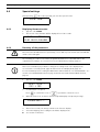
A.7.1
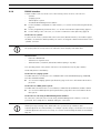
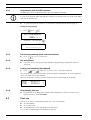
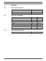
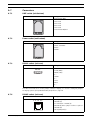
LINE socket (unit bottom)
LINE socket
59
Wiring
1. Flash Data GND
2. Not used
3. Not used
4. Not used
5. Not used
6. Flash Data IN/OUT
1 2 3 456
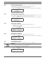
A.7.2
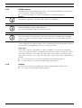
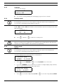
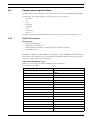
Power socket (unit bottom)
10V AC socket
Wiring
1. Not used
2. AC-1 10-12VAC
3. AC-2
4. GND
1 2 3 4
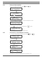
A.7.3
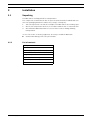
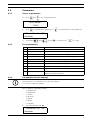
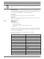
RS-232 socket (unit rear)
RS-232 socket
Wiring
1. ---
54321
2. TXD (RXD)
3. RXD (TXD)
9876
4. --5. GND
6. --7. CTS
8. RTS
9. ---
The values in brackets are for the jumper setting for Paging. See Section Setting the jumpers
for Paging systems (except Medicall 800) and printers:, Page 18.
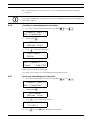
A.7.4
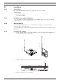
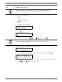
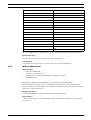
RS-485 socket (unit rear)
RS-485 socket
Wiring
1. Relay output (a)
1 2 3 4 5 6
2. RS485 (A)
3. Termination = RS485 (A)
4. RS485(A) when jumper end line is placed
5. RS485 (B)
6. Relay Output (b)
Bosch Security Systems
User Manual
F.01U.278.515 | V1.0 | 2012.11