1
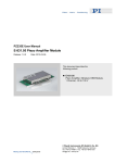
PZ 143E User Manual E-841 / E-842 LVPZT Power Supply Modules Release: 1.3.0 Date: 2012-01-16 This document describes the following product(s): E-841.05 Power Supply Module, 8 W, Input 10 to 30 V E-841.55 Power Supply Module, 20 W, Input 12 to 30 V E-842.05 Power Supply Module, 8 W, Input 30 to 72 V © Physik Instrumente (PI) GmbH & Co. KG Auf der Römerstr. 1 ⋅ 76228 Karlsruhe, Germany Tel. +49 721 4846-0 ⋅ Fax: +49 721 4846-1019 [email protected] ⋅ www.pi.ws Declaration of Conformity according to ISO / IEC Guide 22 and EN 45014 Manufacturer: Physik Instrumente (PI) GmbH & Co. KG Manufacturer´s Address: Auf der Römerstrasse 1 D-76228 Karlsruhe, Germany The manufacturer hereby declares that the product Product Name: Signal Conditioner Electronics Model Numbers: E-841, E-842 Product Options: all complies with the following European directives: 73/23/EEC, Low voltage directive 89/336/EEC, EMC-Directive The applied standards certifying the conformity are listed below. Electromagnetic Emission: EN 61000-6-3, EN 55011 Electromagnetic Immunity: EN 61000-6-1 Safety (Low Voltage Directive): EN 61010-1 Electrical equipment which is intended to be integrated in other electrical equipment, only conforms to the cited EMC Standards and normative documents if the user ensures a compliant connection when implementing the total system. Possible necessary measures are installation of the component in a suitable shielded enclosure and usage of suitable connectors. January 26, 2007 Karlsruhe, Germany Dr. Karl Spanner President Copyright 1999–2012 by Physik Instrumente (PI) GmbH & Co. KG, Karlsruhe, Germany. The texts, photographs and drawings in this manual enjoy copyright protection. With regard thereto, Physik Instrumente (PI) GmbH & Co. KG reserves all rights. Use of said texts, photographs and drawings is permitted only in parts and only upon citation of the source First printing 2012-01-16 Document Number PZ 143E, Release 1.3.0 E-841_User_PZ143E130.doc Subject to change without notice. This manual is superseded by any new release. The newest release is available for download at www.pi.ws. About this Document Users of this Manual This manual is designed to help the reader to install and operate the E-841 / E-842 LVPZT Power Supply Modules. It assumes that the reader has a fundamental understanding of basic servo systems, as well as motion control concepts and applicable safety procedures. The manual describes the physical specifications and dimensions of the E-841 / E-842 LVPZT Power Supply Modules. This document is available as PDF file. Updated releases are available via FTP or email: contact your Physik Instrumente sales engineer or write [email protected]. Conventions The notes and symbols used in this manual have the following meanings: WARNING Calls attention to a procedure, practice or condition which, if not correctly performed or adhered to, could result in injury or death. DANGER Indicates the presence of high voltage (> 50 V). Calls attention to a procedure, practice or condition which, if not correctly performed or adhered to, could result in injury or death. CAUTION Calls attention to a procedure, practice, or condition which, if not correctly performed or adhered to, could result in damage to equipment. NOTE Provides additional information or application hints. Related Documents The E-83x amplifier modules, which might be delivered with E-841 / E-842 LVPZT Power Supply Modules, are described in their own manuals. All documents are available as PDF files. Updated releases are available via FTP or email: contact your Physik Instrumente sales engineer or write [email protected]. ! Introduction 1 Introduction 1.1 1.2 2 Product Features: .....................................................................2 Safety Precautions ....................................................................2 2 Theory of Operation 3 3 Application 4 4 Technical Data 5 4.1 4.2 4.3 4.4 4.5 www.pi.ws Specifications ............................................................................5 E-84x.05 Pin Assignment ..........................................................6 E-841.55 Pin Assignment ..........................................................6 E-84x.05 Case Dimensions .......................................................7 E-841.55 Case Dimensions.......................................................7 E-841 / E-842 PZ 143E Release 1.3.0 Page 1 Introduction 1 Introduction E-841 and E-842 LVPZT power supply modules are switching DC-DC converters supplying the voltages required for piezoelectric actuator amplifiers and designed for PCB mounting. Each module can supply up to three E-831-type amplifiers with all the voltages required. For low-noise applications the power supply can be synchronized with an external clock of 200 kHz. This will keep AC sensors and sampling units from seeing switching noise beat frequencies. 1.1 1.2 Product Features: Low cost Small footprint and low profile Low noise High stability Easy-to-use No external components Fully overcurrent, short-circuit and temperature protected Internal or external clocking Safety Precautions DANGER The PZT driver described in this document outputs voltages of up to 137 V and may cause serious injury. All work done with and on the devices described here requires adequate knowledge and training in handling high voltages. Any cabling or connectors used with the system must meet the local safety requirements for the voltages and currents carried. www.pi.ws E-841 / E-842 PZ 143E Release 1.3.0 Page 2 Theory of Operation 2 Theory of Operation Piezo actuators typically operate at high voltages. To prevent the customer having to generate such untypical voltages by himself, PI offers tested, compatible power supply modules. While for low-noise / high-resolution applications linear power supplies are easier to design, most applications require smaller packages and low power losses. For such applications switched supplies like the E-841/E-842 can be used. Piezo actuators, for mechanical and electrical reasons, are not able to generate mechanical noise at higher frequencies. Therefore power with switching frequency noise of 100 kHz is still suitable for highresolution piezo positioning, even though the electrical signal itself might not qualify as “low-noise.” Care should be taken if the system includes sensors with AC excitation or data sampling. If the different clock signals or their harmonics have frequencies relatively close together, their beat frequency can appear as noise. One example should clarify this: an ac-sensor operates with 100 kHz, the switched power supply at 93 kHz. Now there is a mixed frequency of 100-93 kHz = 7 kHz, that can be seen in both the electrical and mechanical world, because the piezo actuator is able to follow this frequency. The solution PI provides is to make possible synchronization of the power supply with an external clock. The external clock has to be twice the switching clock, so in the example, a master clock of 200 kHz can be used with a divider of 2 for sensor excitation. In complex systems, or when the master clock is much higher and the various frequencies are made by dividers, sometimes more sophisticated synchronization circuits are necessary. This is because the phase shift of different dividers can affect precision and stability. www.pi.ws E-841 / E-842 PZ 143E Release 1.3.0 Page 3 Application 3 Application If the E-841 or 842 is used with E-831 amplifier modules, the pins can be connected directly, and up to three amplifier modules can be supplied. No external components are needed. Input voltage range: • E-841.05: 10 to 30 V • E-841.55: 12 to 30 V • E-842.05: 30 to 72 V The external power supply should be able to provide sufficient power-on current: • E-841.05, E-842.05: 1.5 A for at least 10 ms • E-841.55: 2.5 A for at least 10 ms Operating current is less (see Technical Data, p. 5). Output voltages are not isolated from the input voltage. Fig. 1: Sample system wiring diagram with E-84x.05 power supply module See the E-831 User Manual for details of PZT amplifier operation and signal descriptions. www.pi.ws E-841 / E-842 PZ 143E Release 1.3.0 Page 4 Technical Data 4 Technical Data 4.1 Specifications E-841.05 / E-842.05 E-841.55 Function Power supply module (8 W) for up to 3 × E-831 Power supply module (20 W) for up to 3 × E-831 Output voltages and currents 127 V, 30 mA; -26 V, 30 mA; 15 V, 60 mA; -15 V, 20 mA 137 V, 60 mA -37 V, 60 mA 15 V, 0.3 A -15 V, 0.3 A Max. output power 8W 20 W Average output power 8 W with forced air flow (5 W without) 20 W Current limitation Short-circuit proof (1 minute) Short-circuit proof (1 minute) Operating voltage 10 to 30 V / 30 to 72 V 12 to 30 V Quiescent current 100 mA at 15 V; 60 mA at 30 V; 25 mA at 72 V (E-842.05) 100 mA at 12 V; 90 mA at 15 V; 60 mA at 24 V; 60 mA at 30 V Max. current consumption 1 A (E-841.05 at 10 V); 200 mA (E-842.05 at 72 V) 2.2 A at 12 V; 1.1 A at 24 V Power-on peak current 1.5 A 2.5 A Typ. switching frequency 100 kHz 180 kHz External clock frequency 200 kHz (185 to 220 kHz possible) 200 kHz (200 to 225 kHz possible) Synchronization signal TTL level with 50 % duty cycle; minimum 1.8 Vpp (offset ±7 V) TTL level with 50 % duty cycle; minimum 2.5 Vpp Ripple output <100 mVpp <20 mVpp Operating temperature range 5 to 50 °C (above 40 °C, power derated) 5 to 50 °C (above 40 °C, power derated) Case Metal shielded case, 50 × 44 × 14 mm Metal shielded case, 75 × 62 × 28 mm Contacting Soldering pins, 1 mm Ø, 7 mm Soldering pins, 1 mm Ø, 4 mm www.pi.ws E-841 / E-842 PZ 143E Release 1.3.0 Page 5 Technical Data 4.2 4.3 E-84x.05 Pin Assignment Pin 1 Positive supply input Pin 2 Negative supply input (internally connected to GND) Pin 3 Synchronization (0 V/5 V) Pin 4 Output voltage GND Pin 5 Output voltage +15 V Pin 6 Output voltage -15 V Pin 7 Output voltage -26 V Pin 8 Output voltage +127 V E-841.55 Pin Assignment Pin 1 Positive supply input Pin 2 Negative supply input Pin 3 Output voltage +137 V Pin 4 Output voltage GND Pin 5 Output voltage GND Pin 6 Output voltage -37 V Pin 7 Output voltage GND Pin 8 Output voltage +15 V Pin 9 Output voltage GND Pin 10 Output voltage -15 V Pin 11 not connected Pin 12 Synchronization positive input Pin 13 Synchronization negative input www.pi.ws E-841 / E-842 PZ 143E Release 1.3.0 Page 6 Technical Data 4.4 E-84x.05 Case Dimensions Fig. 2: E-84x.05 case dimensions 4.5 E-841.55 Case Dimensions Fig. 3: E-841.55 case dimensions www.pi.ws E-841 / E-842 PZ 143E Release 1.3.0 Page 7 Technical Data www.pi.ws E-841 / E-842 PZ 143E Release 1.3.0 Page 8