1
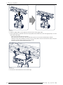
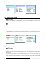
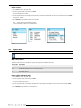
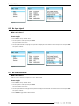
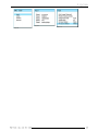
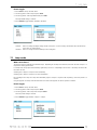
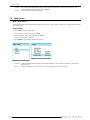
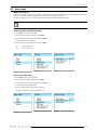
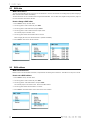
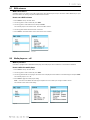
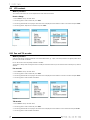
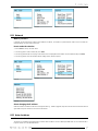
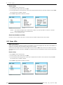
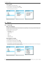
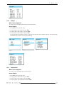
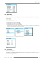
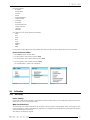
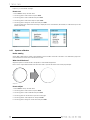
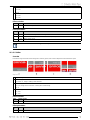
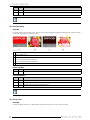
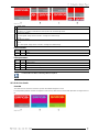
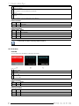
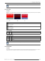
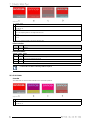
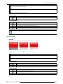
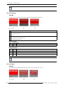
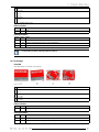
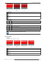
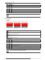
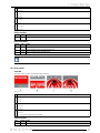
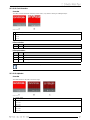
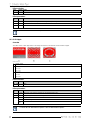
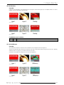
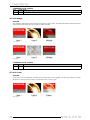
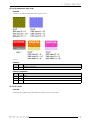
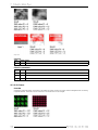
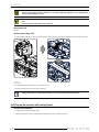
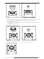
How to set up
1. Press Enter to start up the main menu.
2. Turn the jog dial to select Control and press Enter.
3. Turn the jog dial until the second page of the control menu is displayed and turn further to select Auto shutdown and press Enter.
The selection jumps to disabled or enabled
4. Press Enter to toggle between Disabled or Enabled.
Image 8-35
Image 8-36
Image 8-34
Enabled
Disabled
Auto shutdown will happen after 5 minutes when no DMX is sent to the input AND no connection is available
with a Projector Toolset or an Art-Net DMX device.
no auto shutdown possible.
About Auto shutdown and video
If the DML should not shutdown while video is connected, then the shutdown setting should be set to Disabled.
8.13 Status LEDs
What can be done ?
Status LEDs for Ethernet connection and inputs can be disabled, as well as the backlight of the LCD panel. When disabled, no
indication is on the status LEDs and nothing is displayed on the LCD panel.
With the status LEDs setting enabled, the LCD panel lights up when pressing on Enter. When no more action is taken on the menus,
the backlight goes out after a certain time. With Exit, it is possible to quit the menu immediately and at the same time the backlight
goes out.
How to set up
1. Press Enter to start up the main menu.
2. Turn the jog dial to select Control and press Enter.
3. Turn the jog dial until the third page of the control menu is displayed and turn further to select Status LEDs and press Enter.
The selection jumps to disabled or enabled
4. Press Enter to toggle between Disabled or Enabled.
Image 8-38
Image 8-37
Image 8-39


![DML-1200 [v04]](http://vs1.manualzilla.com/store/data/005824987_1-7e9516eac06e792a0e8f27802b417a45-150x150.png)