1
Copyright © All rights reserved. No part of this document may be copied, reproduced or translated. It shall not otherwise be recorded, transmitted or stored in a retrieval system without the prior written consent of Barco. Federal Communications Commission (FCC Statement) This equipment has been tested and found to comply with the limits for a class A digital device, pursuant to Part 15 of the FCC rules. These limits are designed to provide reasonable protection against harmful interference when the equipment is operated in a commercial environment. This equipment generates, uses, and can radiate radio frequency energy and, if not installed and used in accordance with the instruction manual, may cause harmful interference to radio communications. Operation of this equipment in a residential area may cause harmful interference, in which case the user will be responsible for correcting any interference at his own expense EN55022/CISPR22 Class A ITE (Information Technology Equipment) Class A ITE is a category of all other ITE which satises the class A ITE limits but not the class B ITE limits. Such equipment should not be restricted in its sale but the following warning shall be included in the instructions for use: Warning : This is a class A product. In a domestic environment this product may cause radio interference in which case the user may be required to take adequate measures. Trademarks Brand and product names mentioned in this manual may be trademarks, registered trademarks or copyrights of their respective holders. All brand and product names mentioned in this manual serve as comments or examples and are not to be understood as advertising for the products or their manufacturers. Disposal Information This equipment has required the extraction and use of natural resources for its production. It may contain hazardous substances for health and environment. In order to avoid the dissemination of those substances in the environment and to diminish the pressure on natural resources, we encourage you to use the appropriate take-back systems. Those systems will reuse or recycle most of the materials of your end of life equipment in a sound way. The crossed-out wheeled bin symbol invites you to use those systems. If you need more information on the collection, reuse and recycling systems, please contact your local or regional waste administrator. You can also contact us for more information on the environmental performances of our products. GNU-GPL code If you would like a copy of the GPL source code contained in this product shipped to you on CD, please contact Barco. The cost of preparing and mailing a CD will be charged. Software License Agreement You should carefully read the following terms and conditions before using this software. Your use of this software indicates your acceptance of this license agreement and warranty. Terms and Conditions: 1. No redistribution of the software is allowed. 2. Reverse-Engineering. You may not reverse engineer, decompile, disassemble or alter anyhow this software product. Disclaimer of Warranty: This software and the accompanying les are sold as is and without warranties as to performance or merchantability or any other warranties whether expressed or implied. In no event shall Barco be liable for damage of any kind, loss of data, loss of prots, business interruption or other pecuniary loss arising directly or indirectly. Any liability of the seller will be exclusively limited to replacement of the product or refund of purchase price. Uploading own media It is your responsibility to handle all copyright issues relating to the media you create and upload. Barco will not accept responsibility for any breach of copyright incurred in these processes. Pre-installed media All libraries pre-installed on the system are supplied by Barco. Any queries regarding the use of these should be directed to Barco. Copyright laws may apply. TABLE OF CONTENTS 1. Safety . . . . . .. . . .. . . .. . . .. . . .. . . .. . . .. . . .. . . .. . . .. . . .. . . .. . . .. . . .. . . .. . . .. . . . . .. . . .. . . .. . . .. . . .. . . . . . . .. . . .. . . .. . . .. . . .. 5 1.1 1.2 1.3 1.4 General . . . . . . . . . . . . . . . . . . . . . . . . . . . . . . . . . . . . . . . . . . . . . . . . . . . . . . . . . . . . . . . . . . . . . . . . . . . . . . . . . . . . . . . . . . . . . . . . . . . . . . . . . . . . . . . . . . . . . . . . . . . . . . . Important safety instructions . . . . . . . . . . . . . . . . . . . . . . . . . . . . . . . . . . . . . . . . . . . . . . . . . . . . . . . . . . . . . . . . . . . . . . . . . . . . . . . . . . . . . . . . . . . . . . . . . . . . . . . . . Important warnings concerning DML ight cases . . . . . . . . . . . . . . . . . . . . . . . . . . . . . . . . . . . . . . . . . . . . . . . . . . . . . . . . . . . . . . . . . . . . . . . . . . . . . . . . . . . Recycling guidelines. . . . . . . . . . . . . . . . . . . . . . . . . . . . . . . . . . . . . . . . . . . . . . . . . . . . . . . . . . . . . . . . . . . . . . . . . . . . . . . . . . . . . . . . . . . . . . . . . . . . . . . . . . . . . . . . . . 5 5 8 8 2. General . . . .. . . .. . . .. . . .. . . .. . . .. . . .. . . .. . . .. . . .. . . .. . . .. . . .. . . .. . . .. . . .. . . . . .. . . .. . . .. . . .. . . .. . . .. . . .. . . .. . . .. . . .. . . . 11 2.1 2.2 2.3 Installation requirements . . . . . . . . . . . . . . . . . . . . . . . . . . . . . . . . . . . . . . . . . . . . . . . . . . . . . . . . . . . . . . . . . . . . . . . . . . . . . . . . . . . . . . . . . . . . . . . . . . . . . . . . . . . . 11 Unpacking the device . . . . . . . . . . . . . . . . . . . . . . . . . . . . . . . . . . . . . . . . . . . . . . . . . . . . . . . . . . . . . . . . . . . . . . . . . . . . . . . . . . . . . . . . . . . . . . . . . . . . . . . . . . . . . . . 11 Projector air inlets and outlets. . . . . . . . . . . . . . . . . . . . . . . . . . . . . . . . . . . . . . . . . . . . . . . . . . . . . . . . . . . . . . . . . . . . . . . . . . . . . . . . . . . . . . . . . . . . . . . . . . . . . . . 14 3. Physical installation . . . .. . . .. . . .. . . .. . . .. . . .. . . .. . . .. . . .. . . .. . . .. . . .. . . .. . . .. . . .. . . . . .. . . .. . . .. . . . . . . .. . . .. . . .. . . . 15 3.1 3.2 3.3 Pan and tilt locking . . . . . . . . . . . . . . . . . . . . . . . . . . . . . . . . . . . . . . . . . . . . . . . . . . . . . . . . . . . . . . . . . . . . . . . . . . . . . . . . . . . . . . . . . . . . . . . . . . . . . . . . . . . . . . . . . . 15 Mounting the DML-1200 upright . . . . . . . . . . . . . . . . . . . . . . . . . . . . . . . . . . . . . . . . . . . . . . . . . . . . . . . . . . . . . . . . . . . . . . . . . . . . . . . . . . . . . . . . . . . . . . . . . . . . 17 Truss mounting of the DML-1200 . . . . . . . . . . . . . . . . . . . . . . . . . . . . . . . . . . . . . . . . . . . . . . . . . . . . . . . . . . . . . . . . . . . . . . . . . . . . . . . . . . . . . . . . . . . . . . . . . . . 17 4. Connections . .. . . .. . . .. . . .. . . .. . . .. . . .. . . .. . . .. . . .. . . .. . . .. . . .. . . .. . . .. . . .. . . . . .. . . .. . . .. . . .. . . .. . . .. . . .. . . .. . . .. . . . 21 4.1 4.2 4.3 4.4 Power connection . . . . . . . . . . . . . . . . . . . . . . . . . . . . . . . . . . . . . . . . . . . . . . . . . . . . . . . . . . . . . . . . . . . . . . . . . . . . . . . . . . . . . . . . . . . . . . . . . . . . . . . . . . . . . . . . . . . 21 Input connections . . . . . . . . . . . . . . . . . . . . . . . . . . . . . . . . . . . . . . . . . . . . . . . . . . . . . . . . . . . . . . . . . . . . . . . . . . . . . . . . . . . . . . . . . . . . . . . . . . . . . . . . . . . . . . . . . . . . 22 Communication connections . . . . . . . . . . . . . . . . . . . . . . . . . . . . . . . . . . . . . . . . . . . . . . . . . . . . . . . . . . . . . . . . . . . . . . . . . . . . . . . . . . . . . . . . . . . . . . . . . . . . . . . . 23 Linking DML-1200s . . . . . . . . . . . . . . . . . . . . . . . . . . . . . . . . . . . . . . . . . . . . . . . . . . . . . . . . . . . . . . . . . . . . . . . . . . . . . . . . . . . . . . . . . . . . . . . . . . . . . . . . . . . . . . . . . 26 5. Start up of the Adjustment mode .. . . .. . . .. . . .. . . .. . . .. . . .. . . .. . . .. . . .. . . .. . . .. . . .. . . .. . . .. . . .. . . .. .. . . .. . . .. . . . 29 5.1 5.2 5.3 About the adjustment mode . . . . . . . . . . . . . . . . . . . . . . . . . . . . . . . . . . . . . . . . . . . . . . . . . . . . . . . . . . . . . . . . . . . . . . . . . . . . . . . . . . . . . . . . . . . . . . . . . . . . . . . . . 29 Start up of the adjustment mode . . . . . . . . . . . . . . . . . . . . . . . . . . . . . . . . . . . . . . . . . . . . . . . . . . . . . . . . . . . . . . . . . . . . . . . . . . . . . . . . . . . . . . . . . . . . . . . . . . . . 29 Navigation and adjustments. . . . . . . . . . . . . . . . . . . . . . . . . . . . . . . . . . . . . . . . . . . . . . . . . . . . . . . . . . . . . . . . . . . . . . . . . . . . . . . . . . . . . . . . . . . . . . . . . . . . . . . . . 29 6. Input menu . . .. . . .. . . .. . . .. . . .. . . .. . . .. . . .. . . .. . . .. . . .. . . .. . . .. . . .. . . .. . . . . .. . . .. . . .. . . .. . . .. . . .. . . . . . . .. . . .. . . .. . . . 31 6.1 6.2 6.3 6.4 6.5 6.6 6.7 Input selection . . . . . . . . . . . . . . . . . . . . . . . . . . . . . . . . . . . . . . . . . . . . . . . . . . . . . . . . . . . . . . . . . . . . . . . . . . . . . . . . . . . . . . . . . . . . . . . . . . . . . . . . . . . . . . . . . . . . . . . 31 Auto Image Alignment . . . . . . . . . . . . . . . . . . . . . . . . . . . . . . . . . . . . . . . . . . . . . . . . . . . . . . . . . . . . . . . . . . . . . . . . . . . . . . . . . . . . . . . . . . . . . . . . . . . . . . . . . . . . . . . 31 Reset to factory presets . . . . . . . . . . . . . . . . . . . . . . . . . . . . . . . . . . . . . . . . . . . . . . . . . . . . . . . . . . . . . . . . . . . . . . . . . . . . . . . . . . . . . . . . . . . . . . . . . . . . . . . . . . . . . 32 Image load mode . . . . . . . . . . . . . . . . . . . . . . . . . . . . . . . . . . . . . . . . . . . . . . . . . . . . . . . . . . . . . . . . . . . . . . . . . . . . . . . . . . . . . . . . . . . . . . . . . . . . . . . . . . . . . . . . . . . . 32 Aspect ratio . . . . . . . . . . . . . . . . . . . . . . . . . . . . . . . . . . . . . . . . . . . . . . . . . . . . . . . . . . . . . . . . . . . . . . . . . . . . . . . . . . . . . . . . . . . . . . . . . . . . . . . . . . . . . . . . . . . . . . . . . . 33 No input signal . . . . . . . . . . . . . . . . . . . . . . . . . . . . . . . . . . . . . . . . . . . . . . . . . . . . . . . . . . . . . . . . . . . . . . . . . . . . . . . . . . . . . . . . . . . . . . . . . . . . . . . . . . . . . . . . . . . . . . . 34 No source selected . . . . . . . . . . . . . . . . . . . . . . . . . . . . . . . . . . . . . . . . . . . . . . . . . . . . . . . . . . . . . . . . . . . . . . . . . . . . . . . . . . . . . . . . . . . . . . . . . . . . . . . . . . . . . . . . . . 34 7. Lamp menu . . .. . . .. . . .. . . .. . . .. . . .. . . .. . . .. . . .. . . .. . . .. . . .. . . .. . . .. . . .. . . .. . . . . .. . . .. . . .. . . .. . . .. . . .. . . .. . . .. . . .. . . . 37 7.1 7.2 7.3 7.4 7.5 7.6 Overview ow . . . . . . . . . . . . . . . . . . . . . . . . . . . . . . . . . . . . . . . . . . . . . . . . . . . . . . . . . . . . . . . . . . . . . . . . . . . . . . . . . . . . . . . . . . . . . . . . . . . . . . . . . . . . . . . . . . . . . . . . 37 Identication . . . . . . . . . . . . . . . . . . . . . . . . . . . . . . . . . . . . . . . . . . . . . . . . . . . . . . . . . . . . . . . . . . . . . . . . . . . . . . . . . . . . . . . . . . . . . . . . . . . . . . . . . . . . . . . . . . . . . . . . . 37 Status and run time overview lamps . . . . . . . . . . . . . . . . . . . . . . . . . . . . . . . . . . . . . . . . . . . . . . . . . . . . . . . . . . . . . . . . . . . . . . . . . . . . . . . . . . . . . . . . . . . . . . . . 38 High altitude mode. . . . . . . . . . . . . . . . . . . . . . . . . . . . . . . . . . . . . . . . . . . . . . . . . . . . . . . . . . . . . . . . . . . . . . . . . . . . . . . . . . . . . . . . . . . . . . . . . . . . . . . . . . . . . . . . . . . 38 Lamp mode . . . . . . . . . . . . . . . . . . . . . . . . . . . . . . . . . . . . . . . . . . . . . . . . . . . . . . . . . . . . . . . . . . . . . . . . . . . . . . . . . . . . . . . . . . . . . . . . . . . . . . . . . . . . . . . . . . . . . . . . . . 39 Lamp power. . . . . . . . . . . . . . . . . . . . . . . . . . . . . . . . . . . . . . . . . . . . . . . . . . . . . . . . . . . . . . . . . . . . . . . . . . . . . . . . . . . . . . . . . . . . . . . . . . . . . . . . . . . . . . . . . . . . . . . . . . 40 8. Control menu.. . . .. . . .. . . .. . . .. . . .. . . .. . . .. . . .. . . .. . . .. . . .. . . .. . . .. . . .. . . .. . . . . .. . . .. . . .. . . .. . . .. . . . . . . .. . . .. . . .. . . . 41 8.1 8.2 8.3 8.4 8.5 8.6 8.7 8.8 8.9 8.10 8.11 8.12 8.13 8.14 Overview ow . . . . . . . . . . . . . . . . . . . . . . . . . . . . . . . . . . . . . . . . . . . . . . . . . . . . . . . . . . . . . . . . . . . . . . . . . . . . . . . . . . . . . . . . . . . . . . . . . . . . . . . . . . . . . . . . . . . . . . . . 41 Startup . . . . . . . . . . . . . . . . . . . . . . . . . . . . . . . . . . . . . . . . . . . . . . . . . . . . . . . . . . . . . . . . . . . . . . . . . . . . . . . . . . . . . . . . . . . . . . . . . . . . . . . . . . . . . . . . . . . . . . . . . . . . . . . 42 Standby . . . . . . . . . . . . . . . . . . . . . . . . . . . . . . . . . . . . . . . . . . . . . . . . . . . . . . . . . . . . . . . . . . . . . . . . . . . . . . . . . . . . . . . . . . . . . . . . . . . . . . . . . . . . . . . . . . . . . . . . . . . . . . 42 Demo mode . . . . . . . . . . . . . . . . . . . . . . . . . . . . . . . . . . . . . . . . . . . . . . . . . . . . . . . . . . . . . . . . . . . . . . . . . . . . . . . . . . . . . . . . . . . . . . . . . . . . . . . . . . . . . . . . . . . . . . . . . . 43 DMX data . . . . . . . . . . . . . . . . . . . . . . . . . . . . . . . . . . . . . . . . . . . . . . . . . . . . . . . . . . . . . . . . . . . . . . . . . . . . . . . . . . . . . . . . . . . . . . . . . . . . . . . . . . . . . . . . . . . . . . . . . . . . 44 DMX address . . . . . . . . . . . . . . . . . . . . . . . . . . . . . . . . . . . . . . . . . . . . . . . . . . . . . . . . . . . . . . . . . . . . . . . . . . . . . . . . . . . . . . . . . . . . . . . . . . . . . . . . . . . . . . . . . . . . . . . . 44 DMX universe. . . . . . . . . . . . . . . . . . . . . . . . . . . . . . . . . . . . . . . . . . . . . . . . . . . . . . . . . . . . . . . . . . . . . . . . . . . . . . . . . . . . . . . . . . . . . . . . . . . . . . . . . . . . . . . . . . . . . . . . 45 Media player on - off. . . . . . . . . . . . . . . . . . . . . . . . . . . . . . . . . . . . . . . . . . . . . . . . . . . . . . . . . . . . . . . . . . . . . . . . . . . . . . . . . . . . . . . . . . . . . . . . . . . . . . . . . . . . . . . . . 45 LCD contrast . . . . . . . . . . . . . . . . . . . . . . . . . . . . . . . . . . . . . . . . . . . . . . . . . . . . . . . . . . . . . . . . . . . . . . . . . . . . . . . . . . . . . . . . . . . . . . . . . . . . . . . . . . . . . . . . . . . . . . . . . 46 Pan and Tilt encoder . . . . . . . . . . . . . . . . . . . . . . . . . . . . . . . . . . . . . . . . . . . . . . . . . . . . . . . . . . . . . . . . . . . . . . . . . . . . . . . . . . . . . . . . . . . . . . . . . . . . . . . . . . . . . . . . 46 Network . . . . . . . . . . . . . . . . . . . . . . . . . . . . . . . . . . . . . . . . . . . . . . . . . . . . . . . . . . . . . . . . . . . . . . . . . . . . . . . . . . . . . . . . . . . . . . . . . . . . . . . . . . . . . . . . . . . . . . . . . . . . . . 47 Auto shutdown . . . . . . . . . . . . . . . . . . . . . . . . . . . . . . . . . . . . . . . . . . . . . . . . . . . . . . . . . . . . . . . . . . . . . . . . . . . . . . . . . . . . . . . . . . . . . . . . . . . . . . . . . . . . . . . . . . . . . . . 47 Status LEDs . . . . . . . . . . . . . . . . . . . . . . . . . . . . . . . . . . . . . . . . . . . . . . . . . . . . . . . . . . . . . . . . . . . . . . . . . . . . . . . . . . . . . . . . . . . . . . . . . . . . . . . . . . . . . . . . . . . . . . . . . 48 DMX priority. . . . . . . . . . . . . . . . . . . . . . . . . . . . . . . . . . . . . . . . . . . . . . . . . . . . . . . . . . . . . . . . . . . . . . . . . . . . . . . . . . . . . . . . . . . . . . . . . . . . . . . . . . . . . . . . . . . . . . . . . . 49 9. Service menu. . . . .. . . .. . . .. . . .. . . .. . . .. . . .. . . .. . . .. . . .. . . .. . . .. . . .. . . .. . . .. . . .. . . . . .. . . .. . . .. . . .. . . . . . . .. . . .. . . .. . . . 51 9.1 9.2 9.3 Overview ow . . . . . . . . . . . . . . . . . . . . . . . . . . . . . . . . . . . . . . . . . . . . . . . . . . . . . . . . . . . . . . . . . . . . . . . . . . . . . . . . . . . . . . . . . . . . . . . . . . . . . . . . . . . . . . . . . . . . . . . . 51 Identication . . . . . . . . . . . . . . . . . . . . . . . . . . . . . . . . . . . . . . . . . . . . . . . . . . . . . . . . . . . . . . . . . . . . . . . . . . . . . . . . . . . . . . . . . . . . . . . . . . . . . . . . . . . . . . . . . . . . . . . . . 51 Diagnosis . . . . . . . . . . . . . . . . . . . . . . . . . . . . . . . . . . . . . . . . . . . . . . . . . . . . . . . . . . . . . . . . . . . . . . . . . . . . . . . . . . . . . . . . . . . . . . . . . . . . . . . . . . . . . . . . . . . . . . . . . . . . 52 9.3.1 Version table . . . . . . . . . . . . . . . . . . . . . . . . . . . . . . . . . . . . . . . . . . . . . . . . . . . . . . . . . . . . . . . . . . . . . . . . . . . . . . . . . . . . . . . . . . . . . . . . . . . . . . . . . . . . . . . . . . 52 9.3.2 Voltages . . . . . . . . . . . . . . . . . . . . . . . . . . . . . . . . . . . . . . . . . . . . . . . . . . . . . . . . . . . . . . . . . . . . . . . . . . . . . . . . . . . . . . . . . . . . . . . . . . . . . . . . . . . . . . . . . . . . . . . 53 9.3.3 Temperatures . . . . . . . . . . . . . . . . . . . . . . . . . . . . . . . . . . . . . . . . . . . . . . . . . . . . . . . . . . . . . . . . . . . . . . . . . . . . . . . . . . . . . . . . . . . . . . . . . . . . . . . . . . . . . . . . . 53 9.3.4 Fan speeds. . . . . . . . . . . . . . . . . . . . . . . . . . . . . . . . . . . . . . . . . . . . . . . . . . . . . . . . . . . . . . . . . . . . . . . . . . . . . . . . . . . . . . . . . . . . . . . . . . . . . . . . . . . . . . . . . . . . 54 9.3.5 Device status . . . . . . . . . . . . . . . . . . . . . . . . . . . . . . . . . . . . . . . . . . . . . . . . . . . . . . . . . . . . . . . . . . . . . . . . . . . . . . . . . . . . . . . . . . . . . . . . . . . . . . . . . . . . . . . . . . 55 9.3.6 Error logging . . . . . . . . . . . . . . . . . . . . . . . . . . . . . . . . . . . . . . . . . . . . . . . . . . . . . . . . . . . . . . . . . . . . . . . . . . . . . . . . . . . . . . . . . . . . . . . . . . . . . . . . . . . . . . . . . . 55 9.4 Service patterns . . . . . . . . . . . . . . . . . . . . . . . . . . . . . . . . . . . . . . . . . . . . . . . . . . . . . . . . . . . . . . . . . . . . . . . . . . . . . . . . . . . . . . . . . . . . . . . . . . . . . . . . . . . . . . . . . . . . . 56 9.5 Calibration . . . . . . . . . . . . . . . . . . . . . . . . . . . . . . . . . . . . . . . . . . . . . . . . . . . . . . . . . . . . . . . . . . . . . . . . . . . . . . . . . . . . . . . . . . . . . . . . . . . . . . . . . . . . . . . . . . . . . . . . . . . 57 9.5.1 Index delay . . . . . . . . . . . . . . . . . . . . . . . . . . . . . . . . . . . . . . . . . . . . . . . . . . . . . . . . . . . . . . . . . . . . . . . . . . . . . . . . . . . . . . . . . . . . . . . . . . . . . . . . . . . . . . . . . . . . 57 9.5.2 9.5.3 Aperture calibration . . . . . . . . . . . . . . . . . . . . . . . . . . . . . . . . . . . . . . . . . . . . . . . . . . . . . . . . . . . . . . . . . . . . . . . . . . . . . . . . . . . . . . . . . . . . . . . . . . . . . . . . . . . 58 Device calibration . . . . . . . . . . . . . . . . . . . . . . . . . . . . . . . . . . . . . . . . . . . . . . . . . . . . . . . . . . . . . . . . . . . . . . . . . . . . . . . . . . . . . . . . . . . . . . . . . . . . . . . . . . . . . 59 10. Moving light control via DMX .. . . .. . . .. . . .. . . .. . . .. . . .. . . .. . . .. . . .. . . .. . . .. . . .. . . .. . . .. . . . . .. . . .. . . .. . . .. . . .. . . . 61 10.1 10.2 10.3 10.4 10.5 10.6 10.7 10.8 10.9 Pan - Tilt . . . . . . . . . . . . . . . . . . . . . . . . . . . . . . . . . . . . . . . . . . . . . . . . . . . . . . . . . . . . . . . . . . . . . . . . . . . . . . . . . . . . . . . . . . . . . . . . . . . . . . . . . . . . . . . . . . . . . . . . . . . . . 61 Intensity . . . . . . . . . . . . . . . . . . . . . . . . . . . . . . . . . . . . . . . . . . . . . . . . . . . . . . . . . . . . . . . . . . . . . . . . . . . . . . . . . . . . . . . . . . . . . . . . . . . . . . . . . . . . . . . . . . . . . . . . . . . . . . 61 Optical zoom - focus. . . . . . . . . . . . . . . . . . . . . . . . . . . . . . . . . . . . . . . . . . . . . . . . . . . . . . . . . . . . . . . . . . . . . . . . . . . . . . . . . . . . . . . . . . . . . . . . . . . . . . . . . . . . . . . . . 61 Shutter - Strobe . . . . . . . . . . . . . . . . . . . . . . . . . . . . . . . . . . . . . . . . . . . . . . . . . . . . . . . . . . . . . . . . . . . . . . . . . . . . . . . . . . . . . . . . . . . . . . . . . . . . . . . . . . . . . . . . . . . . . . 61 Cyan - Magenta - Yellow . . . . . . . . . . . . . . . . . . . . . . . . . . . . . . . . . . . . . . . . . . . . . . . . . . . . . . . . . . . . . . . . . . . . . . . . . . . . . . . . . . . . . . . . . . . . . . . . . . . . . . . . . . . . 62 CTO (Color temperature origin) . . . . . . . . . . . . . . . . . . . . . . . . . . . . . . . . . . . . . . . . . . . . . . . . . . . . . . . . . . . . . . . . . . . . . . . . . . . . . . . . . . . . . . . . . . . . . . . . . . . . . 62 Mode selection. . . . . . . . . . . . . . . . . . . . . . . . . . . . . . . . . . . . . . . . . . . . . . . . . . . . . . . . . . . . . . . . . . . . . . . . . . . . . . . . . . . . . . . . . . . . . . . . . . . . . . . . . . . . . . . . . . . . . . . 62 Iris . . . . . . . . . . . . . . . . . . . . . . . . . . . . . . . . . . . . . . . . . . . . . . . . . . . . . . . . . . . . . . . . . . . . . . . . . . . . . . . . . . . . . . . . . . . . . . . . . . . . . . . . . . . . . . . . . . . . . . . . . . . . . . . . . . . . 63 Control channel . . . . . . . . . . . . . . . . . . . . . . . . . . . . . . . . . . . . . . . . . . . . . . . . . . . . . . . . . . . . . . . . . . . . . . . . . . . . . . . . . . . . . . . . . . . . . . . . . . . . . . . . . . . . . . . . . . . . . . 63 11. Image control via DMX . . . . .. . . .. . . .. . . .. . . .. . . .. . . .. . . .. . . .. . . .. . . .. . . .. . . .. . . .. . . .. . . .. . . . . .. . . .. . . . . . . .. . . .. . . . 65 11.1 11.2 11.3 11.4 11.5 11.6 11.7 Introduction . . . . . . . . . . . . . . . . . . . . . . . . . . . . . . . . . . . . . . . . . . . . . . . . . . . . . . . . . . . . . . . . . . . . . . . . . . . . . . . . . . . . . . . . . . . . . . . . . . . . . . . . . . . . . . . . . . . . . . . . . . 65 Source selection . . . . . . . . . . . . . . . . . . . . . . . . . . . . . . . . . . . . . . . . . . . . . . . . . . . . . . . . . . . . . . . . . . . . . . . . . . . . . . . . . . . . . . . . . . . . . . . . . . . . . . . . . . . . . . . . . . . . . 65 Brightness - Contrast - Saturation . . . . . . . . . . . . . . . . . . . . . . . . . . . . . . . . . . . . . . . . . . . . . . . . . . . . . . . . . . . . . . . . . . . . . . . . . . . . . . . . . . . . . . . . . . . . . . . . . . 65 Orientation . . . . . . . . . . . . . . . . . . . . . . . . . . . . . . . . . . . . . . . . . . . . . . . . . . . . . . . . . . . . . . . . . . . . . . . . . . . . . . . . . . . . . . . . . . . . . . . . . . . . . . . . . . . . . . . . . . . . . . . . . . . 65 Blanking . . . . . . . . . . . . . . . . . . . . . . . . . . . . . . . . . . . . . . . . . . . . . . . . . . . . . . . . . . . . . . . . . . . . . . . . . . . . . . . . . . . . . . . . . . . . . . . . . . . . . . . . . . . . . . . . . . . . . . . . . . . . . . 66 Soft edge. . . . . . . . . . . . . . . . . . . . . . . . . . . . . . . . . . . . . . . . . . . . . . . . . . . . . . . . . . . . . . . . . . . . . . . . . . . . . . . . . . . . . . . . . . . . . . . . . . . . . . . . . . . . . . . . . . . . . . . . . . . . . 67 Warping . . . . . . . . . . . . . . . . . . . . . . . . . . . . . . . . . . . . . . . . . . . . . . . . . . . . . . . . . . . . . . . . . . . . . . . . . . . . . . . . . . . . . . . . . . . . . . . . . . . . . . . . . . . . . . . . . . . . . . . . . . . . . . 67 12. Embedded Media Player .. . . . . .. . . .. . . .. . . .. . . .. . . .. . . .. . . .. . . .. . . .. . . .. . . .. . . .. . . .. . . .. . . .. . . . . .. . . .. . . .. . . .. . . . 69 12.1 About the media player . . . . . . . . . . . . . . . . . . . . . . . . . . . . . . . . . . . . . . . . . . . . . . . . . . . . . . . . . . . . . . . . . . . . . . . . . . . . . . . . . . . . . . . . . . . . . . . . . . . . . . . . . . . . . . 69 12.2 Storing images or clips . . . . . . . . . . . . . . . . . . . . . . . . . . . . . . . . . . . . . . . . . . . . . . . . . . . . . . . . . . . . . . . . . . . . . . . . . . . . . . . . . . . . . . . . . . . . . . . . . . . . . . . . . . . . . . 69 12.3 Controlling the Media Player with DMX . . . . . . . . . . . . . . . . . . . . . . . . . . . . . . . . . . . . . . . . . . . . . . . . . . . . . . . . . . . . . . . . . . . . . . . . . . . . . . . . . . . . . . . . . . . . . 69 12.3.1 Image or Clip selection . . . . . . . . . . . . . . . . . . . . . . . . . . . . . . . . . . . . . . . . . . . . . . . . . . . . . . . . . . . . . . . . . . . . . . . . . . . . . . . . . . . . . . . . . . . . . . . . . . . . . . . 69 12.3.2 IN frame - OUT frame. . . . . . . . . . . . . . . . . . . . . . . . . . . . . . . . . . . . . . . . . . . . . . . . . . . . . . . . . . . . . . . . . . . . . . . . . . . . . . . . . . . . . . . . . . . . . . . . . . . . . . . . . 70 12.3.3 Image transition . . . . . . . . . . . . . . . . . . . . . . . . . . . . . . . . . . . . . . . . . . . . . . . . . . . . . . . . . . . . . . . . . . . . . . . . . . . . . . . . . . . . . . . . . . . . . . . . . . . . . . . . . . . . . . . 71 12.3.4 Playback mode and speed . . . . . . . . . . . . . . . . . . . . . . . . . . . . . . . . . . . . . . . . . . . . . . . . . . . . . . . . . . . . . . . . . . . . . . . . . . . . . . . . . . . . . . . . . . . . . . . . . . . 72 12.3.5 Opacity . . . . . . . . . . . . . . . . . . . . . . . . . . . . . . . . . . . . . . . . . . . . . . . . . . . . . . . . . . . . . . . . . . . . . . . . . . . . . . . . . . . . . . . . . . . . . . . . . . . . . . . . . . . . . . . . . . . . . . . . 72 12.3.6 Contrast . . . . . . . . . . . . . . . . . . . . . . . . . . . . . . . . . . . . . . . . . . . . . . . . . . . . . . . . . . . . . . . . . . . . . . . . . . . . . . . . . . . . . . . . . . . . . . . . . . . . . . . . . . . . . . . . . . . . . . . 73 12.3.7 Red - Green - Blue . . . . . . . . . . . . . . . . . . . . . . . . . . . . . . . . . . . . . . . . . . . . . . . . . . . . . . . . . . . . . . . . . . . . . . . . . . . . . . . . . . . . . . . . . . . . . . . . . . . . . . . . . . . . 73 12.3.8 Scale . . . . . . . . . . . . . . . . . . . . . . . . . . . . . . . . . . . . . . . . . . . . . . . . . . . . . . . . . . . . . . . . . . . . . . . . . . . . . . . . . . . . . . . . . . . . . . . . . . . . . . . . . . . . . . . . . . . . . . . . . . 73 12.3.9 Object position . . . . . . . . . . . . . . . . . . . . . . . . . . . . . . . . . . . . . . . . . . . . . . . . . . . . . . . . . . . . . . . . . . . . . . . . . . . . . . . . . . . . . . . . . . . . . . . . . . . . . . . . . . . . . . . . 73 12.3.10 Aspect ratio . . . . . . . . . . . . . . . . . . . . . . . . . . . . . . . . . . . . . . . . . . . . . . . . . . . . . . . . . . . . . . . . . . . . . . . . . . . . . . . . . . . . . . . . . . . . . . . . . . . . . . . . . . . . . . . . . . . 74 12.3.11 Image rotation speed - position. . . . . . . . . . . . . . . . . . . . . . . . . . . . . . . . . . . . . . . . . . . . . . . . . . . . . . . . . . . . . . . . . . . . . . . . . . . . . . . . . . . . . . . . . . . . . . . 74 12.3.12 Image blur . . . . . . . . . . . . . . . . . . . . . . . . . . . . . . . . . . . . . . . . . . . . . . . . . . . . . . . . . . . . . . . . . . . . . . . . . . . . . . . . . . . . . . . . . . . . . . . . . . . . . . . . . . . . . . . . . . . . . 75 12.3.13 Layer effects . . . . . . . . . . . . . . . . . . . . . . . . . . . . . . . . . . . . . . . . . . . . . . . . . . . . . . . . . . . . . . . . . . . . . . . . . . . . . . . . . . . . . . . . . . . . . . . . . . . . . . . . . . . . . . . . . . 75 12.3.13.1 No effect . . . . . . . . . . . . . . . . . . . . . . . . . . . . . . . . . . . . . . . . . . . . . . . . . . . . . . . . . . . . . . . . . . . . . . . . . . . . . . . . . . . . . . . . . . . . . . . . . . . . . . . . . . . . . . . . 75 12.3.13.2 Radial blur . . . . . . . . . . . . . . . . . . . . . . . . . . . . . . . . . . . . . . . . . . . . . . . . . . . . . . . . . . . . . . . . . . . . . . . . . . . . . . . . . . . . . . . . . . . . . . . . . . . . . . . . . . . . . . 75 12.3.13.3 Motion blur . . . . . . . . . . . . . . . . . . . . . . . . . . . . . . . . . . . . . . . . . . . . . . . . . . . . . . . . . . . . . . . . . . . . . . . . . . . . . . . . . . . . . . . . . . . . . . . . . . . . . . . . . . . . . . 76 12.3.13.4 Color Trafo . . . . . . . . . . . . . . . . . . . . . . . . . . . . . . . . . . . . . . . . . . . . . . . . . . . . . . . . . . . . . . . . . . . . . . . . . . . . . . . . . . . . . . . . . . . . . . . . . . . . . . . . . . . . . . 77 12.3.13.5 MultiImage . . . . . . . . . . . . . . . . . . . . . . . . . . . . . . . . . . . . . . . . . . . . . . . . . . . . . . . . . . . . . . . . . . . . . . . . . . . . . . . . . . . . . . . . . . . . . . . . . . . . . . . . . . . . . . 77 12.3.13.6 Inverted lumakey . . . . . . . . . . . . . . . . . . . . . . . . . . . . . . . . . . . . . . . . . . . . . . . . . . . . . . . . . . . . . . . . . . . . . . . . . . . . . . . . . . . . . . . . . . . . . . . . . . . . . . . 78 12.3.13.7 Shifter . . . . . . . . . . . . . . . . . . . . . . . . . . . . . . . . . . . . . . . . . . . . . . . . . . . . . . . . . . . . . . . . . . . . . . . . . . . . . . . . . . . . . . . . . . . . . . . . . . . . . . . . . . . . . . . . . . . 79 12.3.13.8 Chromakey . . . . . . . . . . . . . . . . . . . . . . . . . . . . . . . . . . . . . . . . . . . . . . . . . . . . . . . . . . . . . . . . . . . . . . . . . . . . . . . . . . . . . . . . . . . . . . . . . . . . . . . . . . . . . 80 12.3.13.9 Scroller. . . . . . . . . . . . . . . . . . . . . . . . . . . . . . . . . . . . . . . . . . . . . . . . . . . . . . . . . . . . . . . . . . . . . . . . . . . . . . . . . . . . . . . . . . . . . . . . . . . . . . . . . . . . . . . . . . 80 12.3.13.10 Color Studio . . . . . . . . . . . . . . . . . . . . . . . . . . . . . . . . . . . . . . . . . . . . . . . . . . . . . . . . . . . . . . . . . . . . . . . . . . . . . . . . . . . . . . . . . . . . . . . . . . . . . . . . . . . 81 12.3.13.11 Neon . . . . . . . . . . . . . . . . . . . . . . . . . . . . . . . . . . . . . . . . . . . . . . . . . . . . . . . . . . . . . . . . . . . . . . . . . . . . . . . . . . . . . . . . . . . . . . . . . . . . . . . . . . . . . . . . . . . 82 12.3.13.12 CTBO . . . . . . . . . . . . . . . . . . . . . . . . . . . . . . . . . . . . . . . . . . . . . . . . . . . . . . . . . . . . . . . . . . . . . . . . . . . . . . . . . . . . . . . . . . . . . . . . . . . . . . . . . . . . . . . . . . 83 12.3.13.13 DuoTone . . . . . . . . . . . . . . . . . . . . . . . . . . . . . . . . . . . . . . . . . . . . . . . . . . . . . . . . . . . . . . . . . . . . . . . . . . . . . . . . . . . . . . . . . . . . . . . . . . . . . . . . . . . . . . . 83 12.3.13.14 Palette . . . . . . . . . . . . . . . . . . . . . . . . . . . . . . . . . . . . . . . . . . . . . . . . . . . . . . . . . . . . . . . . . . . . . . . . . . . . . . . . . . . . . . . . . . . . . . . . . . . . . . . . . . . . . . . . . 84 12.3.13.15 Bloom . . . . . . . . . . . . . . . . . . . . . . . . . . . . . . . . . . . . . . . . . . . . . . . . . . . . . . . . . . . . . . . . . . . . . . . . . . . . . . . . . . . . . . . . . . . . . . . . . . . . . . . . . . . . . . . . . . 85 12.3.13.16 Interlace . . . . . . . . . . . . . . . . . . . . . . . . . . . . . . . . . . . . . . . . . . . . . . . . . . . . . . . . . . . . . . . . . . . . . . . . . . . . . . . . . . . . . . . . . . . . . . . . . . . . . . . . . . . . . . . 86 12.3.13.17 Noise. . . . . . . . . . . . . . . . . . . . . . . . . . . . . . . . . . . . . . . . . . . . . . . . . . . . . . . . . . . . . . . . . . . . . . . . . . . . . . . . . . . . . . . . . . . . . . . . . . . . . . . . . . . . . . . . . . . 86 12.3.13.18 Rings. . . . . . . . . . . . . . . . . . . . . . . . . . . . . . . . . . . . . . . . . . . . . . . . . . . . . . . . . . . . . . . . . . . . . . . . . . . . . . . . . . . . . . . . . . . . . . . . . . . . . . . . . . . . . . . . . . . 87 12.3.13.19 CubeStyle . . . . . . . . . . . . . . . . . . . . . . . . . . . . . . . . . . . . . . . . . . . . . . . . . . . . . . . . . . . . . . . . . . . . . . . . . . . . . . . . . . . . . . . . . . . . . . . . . . . . . . . . . . . . . 88 12.3.13.20 LED . . . . . . . . . . . . . . . . . . . . . . . . . . . . . . . . . . . . . . . . . . . . . . . . . . . . . . . . . . . . . . . . . . . . . . . . . . . . . . . . . . . . . . . . . . . . . . . . . . . . . . . . . . . . . . . . . . . . 88 12.3.13.21 Pixetlate . . . . . . . . . . . . . . . . . . . . . . . . . . . . . . . . . . . . . . . . . . . . . . . . . . . . . . . . . . . . . . . . . . . . . . . . . . . . . . . . . . . . . . . . . . . . . . . . . . . . . . . . . . . . . . . 89 12.3.13.22 Halftone. . . . . . . . . . . . . . . . . . . . . . . . . . . . . . . . . . . . . . . . . . . . . . . . . . . . . . . . . . . . . . . . . . . . . . . . . . . . . . . . . . . . . . . . . . . . . . . . . . . . . . . . . . . . . . . . 90 12.3.13.23 Plasma. . . . . . . . . . . . . . . . . . . . . . . . . . . . . . . . . . . . . . . . . . . . . . . . . . . . . . . . . . . . . . . . . . . . . . . . . . . . . . . . . . . . . . . . . . . . . . . . . . . . . . . . . . . . . . . . . 91 12.3.13.24 Flower . . . . . . . . . . . . . . . . . . . . . . . . . . . . . . . . . . . . . . . . . . . . . . . . . . . . . . . . . . . . . . . . . . . . . . . . . . . . . . . . . . . . . . . . . . . . . . . . . . . . . . . . . . . . . . . . . 91 12.3.13.25 Flip . . . . . . . . . . . . . . . . . . . . . . . . . . . . . . . . . . . . . . . . . . . . . . . . . . . . . . . . . . . . . . . . . . . . . . . . . . . . . . . . . . . . . . . . . . . . . . . . . . . . . . . . . . . . . . . . . . . . . 92 12.3.13.26 Rotozoom. . . . . . . . . . . . . . . . . . . . . . . . . . . . . . . . . . . . . . . . . . . . . . . . . . . . . . . . . . . . . . . . . . . . . . . . . . . . . . . . . . . . . . . . . . . . . . . . . . . . . . . . . . . . . . 93 12.3.13.27 Glass. . . . . . . . . . . . . . . . . . . . . . . . . . . . . . . . . . . . . . . . . . . . . . . . . . . . . . . . . . . . . . . . . . . . . . . . . . . . . . . . . . . . . . . . . . . . . . . . . . . . . . . . . . . . . . . . . . . 94 12.3.13.28 Aqua . . . . . . . . . . . . . . . . . . . . . . . . . . . . . . . . . . . . . . . . . . . . . . . . . . . . . . . . . . . . . . . . . . . . . . . . . . . . . . . . . . . . . . . . . . . . . . . . . . . . . . . . . . . . . . . . . . . 94 12.3.13.29 Tunnel . . . . . . . . . . . . . . . . . . . . . . . . . . . . . . . . . . . . . . . . . . . . . . . . . . . . . . . . . . . . . . . . . . . . . . . . . . . . . . . . . . . . . . . . . . . . . . . . . . . . . . . . . . . . . . . . . 95 12.3.13.30 Planes . . . . . . . . . . . . . . . . . . . . . . . . . . . . . . . . . . . . . . . . . . . . . . . . . . . . . . . . . . . . . . . . . . . . . . . . . . . . . . . . . . . . . . . . . . . . . . . . . . . . . . . . . . . . . . . . . 96 12.3.13.31 Fluid distortion . . . . . . . . . . . . . . . . . . . . . . . . . . . . . . . . . . . . . . . . . . . . . . . . . . . . . . . . . . . . . . . . . . . . . . . . . . . . . . . . . . . . . . . . . . . . . . . . . . . . . . . . . 97 12.3.13.32 Alphabet . . . . . . . . . . . . . . . . . . . . . . . . . . . . . . . . . . . . . . . . . . . . . . . . . . . . . . . . . . . . . . . . . . . . . . . . . . . . . . . . . . . . . . . . . . . . . . . . . . . . . . . . . . . . . . . 97 12.3.13.33 Ripple . . . . . . . . . . . . . . . . . . . . . . . . . . . . . . . . . . . . . . . . . . . . . . . . . . . . . . . . . . . . . . . . . . . . . . . . . . . . . . . . . . . . . . . . . . . . . . . . . . . . . . . . . . . . . . . . . . 98 12.3.13.34 Wave. . . . . . . . . . . . . . . . . . . . . . . . . . . . . . . . . . . . . . . . . . . . . . . . . . . . . . . . . . . . . . . . . . . . . . . . . . . . . . . . . . . . . . . . . . . . . . . . . . . . . . . . . . . . . . . . . . . 99 12.3.13.35 Jitter . . . . . . . . . . . . . . . . . . . . . . . . . . . . . . . . . . . . . . . . . . . . . . . . . . . . . . . . . . . . . . . . . . . . . . . . . . . . . . . . . . . . . . . . . . . . . . . . . . . . . . . . . . . . . . . . . . . 99 12.3.13.36 Stripes . . . . . . . . . . . . . . . . . . . . . . . . . . . . . . . . . . . . . . . . . . . . . . . . . . . . . . . . . . . . . . . . . . . . . . . . . . . . . . . . . . . . . . . . . . . . . . . . . . . . . . . . . . . . . . . .100 12.3.13.37 Innite Zoom. . . . . . . . . . . . . . . . . . . . . . . . . . . . . . . . . . . . . . . . . . . . . . . . . . . . . . . . . . . . . . . . . . . . . . . . . . . . . . . . . . . . . . . . . . . . . . . . . . . . . . . . . .101 12.3.13.38 Innity. . . . . . . . . . . . . . . . . . . . . . . . . . . . . . . . . . . . . . . . . . . . . . . . . . . . . . . . . . . . . . . . . . . . . . . . . . . . . . . . . . . . . . . . . . . . . . . . . . . . . . . . . . . . . . . . .101 12.3.13.39 Blinder . . . . . . . . . . . . . . . . . . . . . . . . . . . . . . . . . . . . . . . . . . . . . . . . . . . . . . . . . . . . . . . . . . . . . . . . . . . . . . . . . . . . . . . . . . . . . . . . . . . . . . . . . . . . . . . .102 12.3.14 Layer combination mode . . . . . . . . . . . . . . . . . . . . . . . . . . . . . . . . . . . . . . . . . . . . . . . . . . . . . . . . . . . . . . . . . . . . . . . . . . . . . . . . . . . . . . . . . . . . . . . . . . . . 102 12.3.14.1 Introduction . . . . . . . . . . . . . . . . . . . . . . . . . . . . . . . . . . . . . . . . . . . . . . . . . . . . . . . . . . . . . . . . . . . . . . . . . . . . . . . . . . . . . . . . . . . . . . . . . . . . . . . . . . . .102 12.3.14.2 Add. . . . . . . . . . . . . . . . . . . . . . . . . . . . . . . . . . . . . . . . . . . . . . . . . . . . . . . . . . . . . . . . . . . . . . . . . . . . . . . . . . . . . . . . . . . . . . . . . . . . . . . . . . . . . . . . . . . . .103 12.3.14.3 Sub. . . . . . . . . . . . . . . . . . . . . . . . . . . . . . . . . . . . . . . . . . . . . . . . . . . . . . . . . . . . . . . . . . . . . . . . . . . . . . . . . . . . . . . . . . . . . . . . . . . . . . . . . . . . . . . . . . . . .104 12.3.14.4 Darken . . . . . . . . . . . . . . . . . . . . . . . . . . . . . . . . . . . . . . . . . . . . . . . . . . . . . . . . . . . . . . . . . . . . . . . . . . . . . . . . . . . . . . . . . . . . . . . . . . . . . . . . . . . . . . . . .104 12.3.14.5 Lighten . . . . . . . . . . . . . . . . . . . . . . . . . . . . . . . . . . . . . . . . . . . . . . . . . . . . . . . . . . . . . . . . . . . . . . . . . . . . . . . . . . . . . . . . . . . . . . . . . . . . . . . . . . . . . . . . .104 12.3.14.6 Softlight . . . . . . . . . . . . . . . . . . . . . . . . . . . . . . . . . . . . . . . . . . . . . . . . . . . . . . . . . . . . . . . . . . . . . . . . . . . . . . . . . . . . . . . . . . . . . . . . . . . . . . . . . . . . . . . .105 12.3.14.7 Softlight inverse . . . . . . . . . . . . . . . . . . . . . . . . . . . . . . . . . . . . . . . . . . . . . . . . . . . . . . . . . . . . . . . . . . . . . . . . . . . . . . . . . . . . . . . . . . . . . . . . . . . . . . .105 12.3.14.8 Hardlight . . . . . . . . . . . . . . . . . . . . . . . . . . . . . . . . . . . . . . . . . . . . . . . . . . . . . . . . . . . . . . . . . . . . . . . . . . . . . . . . . . . . . . . . . . . . . . . . . . . . . . . . . . . . . . .106 12.3.14.9 Overlay . . . . . . . . . . . . . . . . . . . . . . . . . . . . . . . . . . . . . . . . . . . . . . . . . . . . . . . . . . . . . . . . . . . . . . . . . . . . . . . . . . . . . . . . . . . . . . . . . . . . . . . . . . . . . . . .107 12.3.14.10 Difference. . . . . . . . . . . . . . . . . . . . . . . . . . . . . . . . . . . . . . . . . . . . . . . . . . . . . . . . . . . . . . . . . . . . . . . . . . . . . . . . . . . . . . . . . . . . . . . . . . . . . . . . . . . . .107 12.3.14.11 Multiply. . . . . . . . . . . . . . . . . . . . . . . . . . . . . . . . . . . . . . . . . . . . . . . . . . . . . . . . . . . . . . . . . . . . . . . . . . . . . . . . . . . . . . . . . . . . . . . . . . . . . . . . . . . . . . . .108 12.3.14.12 Screen . . . . . . . . . . . . . . . . . . . . . . . . . . . . . . . . . . . . . . . . . . . . . . . . . . . . . . . . . . . . . . . . . . . . . . . . . . . . . . . . . . . . . . . . . . . . . . . . . . . . . . . . . . . . . . . .108 12.3.14.13 Opaque . . . . . . . . . . . . . . . . . . . . . . . . . . . . . . . . . . . . . . . . . . . . . . . . . . . . . . . . . . . . . . . . . . . . . . . . . . . . . . . . . . . . . . . . . . . . . . . . . . . . . . . . . . . . . . .109 12.3.14.14 Sprite . . . . . . . . . . . . . . . . . . . . . . . . . . . . . . . . . . . . . . . . . . . . . . . . . . . . . . . . . . . . . . . . . . . . . . . . . . . . . . . . . . . . . . . . . . . . . . . . . . . . . . . . . . . . . . . . .109 12.3.14.15 Luminance key . . . . . . . . . . . . . . . . . . . . . . . . . . . . . . . . . . . . . . . . . . . . . . . . . . . . . . . . . . . . . . . . . . . . . . . . . . . . . . . . . . . . . . . . . . . . . . . . . . . . . . . 110 12.3.14.16 Matte . . . . . . . . . . . . . . . . . . . . . . . . . . . . . . . . . . . . . . . . . . . . . . . . . . . . . . . . . . . . . . . . . . . . . . . . . . . . . . . . . . . . . . . . . . . . . . . . . . . . . . . . . . . . . . . . . . 111 12.3.15 Matte layer selections. . . . . . . . . . . . . . . . . . . . . . . . . . . . . . . . . . . . . . . . . . . . . . . . . . . . . . . . . . . . . . . . . . . . . . . . . . . . . . . . . . . . . . . . . . . . . . . . . . . . . . . . 111 12.3.15.1 Introduction . . . . . . . . . . . . . . . . . . . . . . . . . . . . . . . . . . . . . . . . . . . . . . . . . . . . . . . . . . . . . . . . . . . . . . . . . . . . . . . . . . . . . . . . . . . . . . . . . . . . . . . . . . . . 111 12.3.15.2 Color . . . . . . . . . . . . . . . . . . . . . . . . . . . . . . . . . . . . . . . . . . . . . . . . . . . . . . . . . . . . . . . . . . . . . . . . . . . . . . . . . . . . . . . . . . . . . . . . . . . . . . . . . . . . . . . . . . 112 12.3.15.3 Rings. . . . . . . . . . . . . . . . . . . . . . . . . . . . . . . . . . . . . . . . . . . . . . . . . . . . . . . . . . . . . . . . . . . . . . . . . . . . . . . . . . . . . . . . . . . . . . . . . . . . . . . . . . . . . . . . . . . 112 12.3.15.4 Chess . . . . . . . . . . . . . . . . . . . . . . . . . . . . . . . . . . . . . . . . . . . . . . . . . . . . . . . . . . . . . . . . . . . . . . . . . . . . . . . . . . . . . . . . . . . . . . . . . . . . . . . . . . . . . . . . . . 113 12.3.15.5 Interference (C+C) . . . . . . . . . . . . . . . . . . . . . . . . . . . . . . . . . . . . . . . . . . . . . . . . . . . . . . . . . . . . . . . . . . . . . . . . . . . . . . . . . . . . . . . . . . . . . . . . . . . . 114 12.3.15.6 Interferences, Retro (C+C). . . . . . . . . . . . . . . . . . . . . . . . . . . . . . . . . . . . . . . . . . . . . . . . . . . . . . . . . . . . . . . . . . . . . . . . . . . . . . . . . . . . . . . . . . . . 115 12.3.15.7 Interferences (R+C) . . . . . . . . . . . . . . . . . . . . . . . . . . . . . . . . . . . . . . . . . . . . . . . . . . . . . . . . . . . . . . . . . . . . . . . . . . . . . . . . . . . . . . . . . . . . . . . . . . . 115 12.3.15.8 Interference, Retro (R+C) . . . . . . . . . . . . . . . . . . . . . . . . . . . . . . . . . . . . . . . . . . . . . . . . . . . . . . . . . . . . . . . . . . . . . . . . . . . . . . . . . . . . . . . . . . . . . 116 12.3.15.9 Interference, Retro2 (R+C). . . . . . . . . . . . . . . . . . . . . . . . . . . . . . . . . . . . . . . . . . . . . . . . . . . . . . . . . . . . . . . . . . . . . . . . . . . . . . . . . . . . . . . . . . . . 117 12.3.15.10 Interference (R+R) . . . . . . . . . . . . . . . . . . . . . . . . . . . . . . . . . . . . . . . . . . . . . . . . . . . . . . . . . . . . . . . . . . . . . . . . . . . . . . . . . . . . . . . . . . . . . . . . . . . 118 12.3.15.11 Interference Retro (R+R). . . . . . . . . . . . . . . . . . . . . . . . . . . . . . . . . . . . . . . . . . . . . . . . . . . . . . . . . . . . . . . . . . . . . . . . . . . . . . . . . . . . . . . . . . . . . 119 12.3.15.12 Clouds . . . . . . . . . . . . . . . . . . . . . . . . . . . . . . . . . . . . . . . . . . . . . . . . . . . . . . . . . . . . . . . . . . . . . . . . . . . . . . . . . . . . . . . . . . . . . . . . . . . . . . . . . . . . . . . . 119 12.3.15.13 Flowers . . . . . . . . . . . . . . . . . . . . . . . . . . . . . . . . . . . . . . . . . . . . . . . . . . . . . . . . . . . . . . . . . . . . . . . . . . . . . . . . . . . . . . . . . . . . . . . . . . . . . . . . . . . . . . .120 12.3.15.14 Fog. . . . . . . . . . . . . . . . . . . . . . . . . . . . . . . . . . . . . . . . . . . . . . . . . . . . . . . . . . . . . . . . . . . . . . . . . . . . . . . . . . . . . . . . . . . . . . . . . . . . . . . . . . . . . . . . . . . .121 12.3.15.15 Rain . . . . . . . . . . . . . . . . . . . . . . . . . . . . . . . . . . . . . . . . . . . . . . . . . . . . . . . . . . . . . . . . . . . . . . . . . . . . . . . . . . . . . . . . . . . . . . . . . . . . . . . . . . . . . . . . . . .122 12.3.15.16 Stareld . . . . . . . . . . . . . . . . . . . . . . . . . . . . . . . . . . . . . . . . . . . . . . . . . . . . . . . . . . . . . . . . . . . . . . . . . . . . . . . . . . . . . . . . . . . . . . . . . . . . . . . . . . . . . . .123 12.3.15.17 Gradient . . . . . . . . . . . . . . . . . . . . . . . . . . . . . . . . . . . . . . . . . . . . . . . . . . . . . . . . . . . . . . . . . . . . . . . . . . . . . . . . . . . . . . . . . . . . . . . . . . . . . . . . . . . . . .123 12.3.16 Warp selection and Warp transition . . . . . . . . . . . . . . . . . . . . . . . . . . . . . . . . . . . . . . . . . . . . . . . . . . . . . . . . . . . . . . . . . . . . . . . . . . . . . . . . . . . . . . . . .124 12.3.17 Masking . . . . . . . . . . . . . . . . . . . . . . . . . . . . . . . . . . . . . . . . . . . . . . . . . . . . . . . . . . . . . . . . . . . . . . . . . . . . . . . . . . . . . . . . . . . . . . . . . . . . . . . . . . . . . . . . . . . . . .124 12.3.18 Master effects . . . . . . . . . . . . . . . . . . . . . . . . . . . . . . . . . . . . . . . . . . . . . . . . . . . . . . . . . . . . . . . . . . . . . . . . . . . . . . . . . . . . . . . . . . . . . . . . . . . . . . . . . . . . . . . .126 12.3.19 Keystone - polygon adjustments . . . . . . . . . . . . . . . . . . . . . . . . . . . . . . . . . . . . . . . . . . . . . . . . . . . . . . . . . . . . . . . . . . . . . . . . . . . . . . . . . . . . . . . . . . . .126 13. Maintenance. . . . . .. . . .. . . .. . . .. . . .. . . .. . . .. . . .. . . .. . . .. . . .. . . .. . . .. . . .. . . .. . . .. . . . . .. . . .. . . .. . . .. . . .. . . .. . . .. . . .. . 129 13.1 13.2 13.3 13.4 Cleaning the lens . . . . . . . . . . . . . . . . . . . . . . . . . . . . . . . . . . . . . . . . . . . . . . . . . . . . . . . . . . . . . . . . . . . . . . . . . . . . . . . . . . . . . . . . . . . . . . . . . . . . . . . . . . . . . . . . . . .129 Cleaning the exterior of the DML-1200 . . . . . . . . . . . . . . . . . . . . . . . . . . . . . . . . . . . . . . . . . . . . . . . . . . . . . . . . . . . . . . . . . . . . . . . . . . . . . . . . . . . . . . . . . . . .129 Level check of cooling liquid . . . . . . . . . . . . . . . . . . . . . . . . . . . . . . . . . . . . . . . . . . . . . . . . . . . . . . . . . . . . . . . . . . . . . . . . . . . . . . . . . . . . . . . . . . . . . . . . . . . . . . .129 Safety cable check . . . . . . . . . . . . . . . . . . . . . . . . . . . . . . . . . . . . . . . . . . . . . . . . . . . . . . . . . . . . . . . . . . . . . . . . . . . . . . . . . . . . . . . . . . . . . . . . . . . . . . . . . . . . . . . . .131 14. Servicing . .. . . .. . . .. . . .. . . .. . . .. . . .. . . .. . . .. . . .. . . .. . . .. . . .. . . .. . . .. . . .. . . .. .. . . .. . . .. . . .. . . .. . . . . . . .. . . .. . . .. . . .. . 135 14.1 Removal of the front cover . . . . . . . . . . . . . . . . . . . . . . . . . . . . . . . . . . . . . . . . . . . . . . . . . . . . . . . . . . . . . . . . . . . . . . . . . . . . . . . . . . . . . . . . . . . . . . . . . . . . . . . . .135 14.2 Opening the top cover on the lamp units side . . . . . . . . . . . . . . . . . . . . . . . . . . . . . . . . . . . . . . . . . . . . . . . . . . . . . . . . . . . . . . . . . . . . . . . . . . . . . . . . . . . . .136 14.3 Opening the top cover on the LPS box side . . . . . . . . . . . . . . . . . . . . . . . . . . . . . . . . . . . . . . . . . . . . . . . . . . . . . . . . . . . . . . . . . . . . . . . . . . . . . . . . . . . . . . .138 14.4 Remove the yoke covers and shields. . . . . . . . . . . . . . . . . . . . . . . . . . . . . . . . . . . . . . . . . . . . . . . . . . . . . . . . . . . . . . . . . . . . . . . . . . . . . . . . . . . . . . . . . . . . . .139 14.5 Remove top cover of base unit. . . . . . . . . . . . . . . . . . . . . . . . . . . . . . . . . . . . . . . . . . . . . . . . . . . . . . . . . . . . . . . . . . . . . . . . . . . . . . . . . . . . . . . . . . . . . . . . . . . . .141 14.6 Replacement of the dust lters on the front side . . . . . . . . . . . . . . . . . . . . . . . . . . . . . . . . . . . . . . . . . . . . . . . . . . . . . . . . . . . . . . . . . . . . . . . . . . . . . . . . . .142 14.7 Replacement of the dust lter at the inside of the head . . . . . . . . . . . . . . . . . . . . . . . . . . . . . . . . . . . . . . . . . . . . . . . . . . . . . . . . . . . . . . . . . . . . . . . . . . .143 14.8 Replacement of the dust lter in the base . . . . . . . . . . . . . . . . . . . . . . . . . . . . . . . . . . . . . . . . . . . . . . . . . . . . . . . . . . . . . . . . . . . . . . . . . . . . . . . . . . . . . . . . .144 14.9 Removal of a lamp unit . . . . . . . . . . . . . . . . . . . . . . . . . . . . . . . . . . . . . . . . . . . . . . . . . . . . . . . . . . . . . . . . . . . . . . . . . . . . . . . . . . . . . . . . . . . . . . . . . . . . . . . . . . . . .145 14.10 Mounting a new lamp unit . . . . . . . . . . . . . . . . . . . . . . . . . . . . . . . . . . . . . . . . . . . . . . . . . . . . . . . . . . . . . . . . . . . . . . . . . . . . . . . . . . . . . . . . . . . . . . . . . . . . . . . . . .147 14.11 Top-up the reservoir with cooling liquid . . . . . . . . . . . . . . . . . . . . . . . . . . . . . . . . . . . . . . . . . . . . . . . . . . . . . . . . . . . . . . . . . . . . . . . . . . . . . . . . . . . . . . . . . . . .148 A. DMX chart . . . . . .. . . .. . . .. . . .. . . .. . . .. . . .. . . .. . . .. . . .. . . .. . . .. . . .. . . .. . . .. . . .. . . . . .. . . .. . . .. . . .. . . .. . . .. . . .. . . .. . . .. . 153 A.1 A.2 A.3 DMX chart, Digital moving luminiere . . . . . . . . . . . . . . . . . . . . . . . . . . . . . . . . . . . . . . . . . . . . . . . . . . . . . . . . . . . . . . . . . . . . . . . . . . . . . . . . . . . . . . . . . . . . . . .153 DMX chart, Image . . . . . . . . . . . . . . . . . . . . . . . . . . . . . . . . . . . . . . . . . . . . . . . . . . . . . . . . . . . . . . . . . . . . . . . . . . . . . . . . . . . . . . . . . . . . . . . . . . . . . . . . . . . . . . . . . .154 DMX chart, EMP . . . . . . . . . . . . . . . . . . . . . . . . . . . . . . . . . . . . . . . . . . . . . . . . . . . . . . . . . . . . . . . . . . . . . . . . . . . . . . . . . . . . . . . . . . . . . . . . . . . . . . . . . . . . . . . . . . . .156 B. Dimensions . . . .. . . .. . . .. . . .. . . .. . . .. . . .. . . .. . . .. . . .. . . .. . . .. . . .. . . .. . . .. . . .. . . . . .. . . .. . . .. . . .. . . .. . . .. . . .. . . .. . . .. . 163 B.1 B.2 Dimensions of the DML-1200 . . . . . . . . . . . . . . . . . . . . . . . . . . . . . . . . . . . . . . . . . . . . . . . . . . . . . . . . . . . . . . . . . . . . . . . . . . . . . . . . . . . . . . . . . . . . . . . . . . . . . .163 Dimensions ight case . . . . . . . . . . . . . . . . . . . . . . . . . . . . . . . . . . . . . . . . . . . . . . . . . . . . . . . . . . . . . . . . . . . . . . . . . . . . . . . . . . . . . . . . . . . . . . . . . . . . . . . . . . . . .164 C. Troubleshooting . .. . . .. . . .. . . .. . . .. . . .. . . .. . . .. . . .. . . .. . . .. . . .. . . .. . . .. . . .. . . .. . . . . .. . . .. . . .. . . .. . . .. . . .. . . .. . . .. . 165 C.1 Error list . . . . . . . . . . . . . . . . . . . . . . . . . . . . . . . . . . . . . . . . . . . . . . . . . . . . . . . . . . . . . . . . . . . . . . . . . . . . . . . . . . . . . . . . . . . . . . . . . . . . . . . . . . . . . . . . . . . . . . . . . . . . .165 D. Specications . . . . .. . . .. . . .. . . .. . . .. . . .. . . .. . . .. . . .. . . .. . . .. . . .. . . .. . . .. . . .. . . .. . . . . .. . . .. . . .. . . .. . . .. . . .. . . .. . . .. . 169 D.1 Specications of the DML-1200 . . . . . . . . . . . . . . . . . . . . . . . . . . . . . . . . . . . . . . . . . . . . . . . . . . . . . . . . . . . . . . . . . . . . . . . . . . . . . . . . . . . . . . . . . . . . . . . . . . . .169 E. Order info . .. . . .. . . .. . . .. . . .. . . .. . . .. . . .. . . .. . . .. . . .. . . .. . . .. . . .. . . .. . . .. . . . . .. . . .. . . .. . . .. . . .. . . .. . . .. . . .. . . .. . . .. . 171 E.1 Spare part order info . . . . . . . . . . . . . . . . . . . . . . . . . . . . . . . . . . . . . . . . . . . . . . . . . . . . . . . . . . . . . . . . . . . . . . . . . . . . . . . . . . . . . . . . . . . . . . . . . . . . . . . . . . . . . . .171 1. SAFETY 1.1 General Personal protection Take care of the following warnings and cautions: WARNING : Ensure you understand and follow all the safety guidelines, safety instructions, warnings and cautions mentioned in this manual. WARNING : Be aware of suspended loads. WARNING : Wear a hard hat to reduce the risk of personal injury. WARNING : Be careful while working with heavy loads. WARNING : Mind your ngers while working with heavy loads. CAUTION: 1.2 High pressure lamp may explode if improperly handled. Important safety instructions To prevent the risk of electrical shock This product should be operated from a mono phase AC power source. Power input voltage range must be between 200-240 V,10A 50/60Hz Warning: This apparatus must be grounded (earthed) via the supplied 3 conductor AC power cable. Mount a plug to the delivered power cord but take care of the local regulations about power cords and power plugs. Do not defeat the purpose of the grounding-type plug. Do not allow anything to rest on the power cord. Do not locate this product where persons will walk on the cord. To disconnect the cord, pull it out by the plug. Never pull the cord itself. If an extension cord is used with this product, make sure that the total of the ampere ratings on the products plugged into the extension cord does not exceed the extension cord ampere rating. Use only the power cord supplied with your device. While appearing to be similar, other power cords have not been safety tested at the factory and may not be used to power the device. For a replacement power cord, contact your dealer. Never push objects of any kind into this product through cabinet slots as they may touch dangerous voltage points or short out parts that could result in a risk of re or electrical shock. Never spill liquid of any kind on the product. Should any liquid or solid object fall into the cabinet, unplug the set and have it checked by qualied service personnel before resuming operations. Lightning - For added protection for this video product during a lightning storm, or when it is left unattended and unused for long periods of time, unplug it from the wall outlet. This will prevent damage to the device due to lightning and AC power-line surges. Do not guide the power cord over the base unit of the device. Ensure that the power cord cannot make contact with moving head. To prevent personal injury When power is supplied to the device, the device starts a homing procedure which includes a movement of the head. When opening one of the shell covers of the projector head while power is supplied to the device, the movement of the head (pan and tilt) is blocked by the software. To reduce the lamp heat of the projector head, switch the device rst to standby and let the projector lamp cool down for at least 5 minutes. Then the device may be disconnected from the power outlet. Isolated electrically before re-lamping. Caution : hot lamps. The customer should never attempt to disassemble the lamp casing. See "Recycling guidelines", page 8 for more information about handling a used lamp. To prevent injury and physical damage, always read this manual and all labels on the system before inserting the lamp casing, connecting to the wall outlet or adjusting the projector. To prevent injury, take note of the weight of the projector. Minimum 2 persons are needed to lift up the device. No twist is allowed. When lifting out of the ight case, a 3rd person has to push away the ight case while the rst 2 are lifting up the device. To prevent injury, ensure that the lens and all cover plates are correctly installed. See installation procedures. Warning: high intensity light beam. NEVER look into the lens ! High luminance could result in injury to the eye. Before attempting to remove any of the devices covers, you must disconnect from the wall outlet. When performing setup work to a ceiling mounted device, to prevent injury caused by falling objects or the system, set out a keep out area. Consult a professional structural engineer prior to suspending the device from a structure not intended for that use. Always ensure that the working load limit of the structure can handle the load of the device. The power input at the base of the device is considered as the disconnect device. When required to switch off the device, to access parts inside, always disconnect the power cord at the base of the device. In case the power input at the base of the device is not accessible (e.g. ceiling mount), the socket outlet supplying the device shall be installed nearby the device and be easily accessible, or a readily accessible general disconnect device shall be incorporated in the xed wiring. Do not place this equipment on an unstable cart, stand, or table. The product may fall, causing serious damage to it and possible injury to the user. When mounting the device to the ceiling or to a rigging system, always mount the delivered security cables and connectors. Before mounting the security cable, inspect the cable and connector. Do not use when visible damage is detected. Stretch the security cable completely. If necessary, turn the security cable a few times around the truss before closing the connection so that the cable is stretched as much as possible. Connector may not be mounted under bending stress. It is hazardous to operate without lens or shield. Shields, lenses or utra-vilolet screens shall be changed if they have become visible damaged to such an extent that their effectiveness is impaired. For example by cracks or deep scratches. Mercury Vapor Warnings: Keep the following warnings in mind when using the projector. The lamp used in the projector contains mercury. In case of a lamp rupture, explosion there will be a mercury vapor emission. In order to minimize the potential risk of inhaling mercury vapors: - Ensure the projector is installed only in ventilated rooms. - Replace the lamp module before the end of its operational life. - Promptly ventilate the room after a lamp rupture, explosion has occurred, evacuate the room (particularly in case of a pregnant woman). - Seek medical attention if unusual health conditions occur after a lamp rupture, explosion, such as headache, fatigue, shortness of breath, chest-tightening coughing or nausea. Cooling liquid circuit. The device head contains a cooling circuit lled with Blue antifreeze diluted 1,2 ethanediol (1/3 ethanediol 2/3 Demi water). When the cooling circuit leaks, switch off the device and contact a service technician. The liquid is not for household use. Keep out of reach of children. Harmful by oral intake. Avoid exposure to pregnant women. Avoid contact with eyes, skin and clothing. Avoid inhale of the noxious fumes. Restricted Access Location The DML must be installed in a Restricted Access Location, where access can only be gained by persons who have been instructed about the reasons for the restriction applied to the location and about the precautions that shall be taken. Reasons for the applied restrictions: moving head in all directions, air outlet can reach high temperatures and light output may cause eye injury when looking directly into the lens. Maximum temperature of enclosure : 90°C (194 °F) To prevent device damage The DML has been designed for use with a specic lamp type. See installation instructions for its correct lamp type. If the air lters are not regularly replaced, the air ow inside the device (projector head and base) could be disrupted, causing overheating. Overheating may lead to the device shutting down during operation. In order to ensure that correct airow is maintained, and that the device complies with electromagnetic compatibility (EMC) requirements, and for safety requirements, it should always be operated with all of its covers in place. Slots and openings in the cabinet are provided for ventilation. To ensure reliable operation of the product and to protect it from overheating, these openings must not be blocked or covered. The openings should never be blocked by placing the product on a bed, sofa, rug, or other similar surface. This product should never be placed near or over a radiator or heat register. The device should not be placed in a built-in installation or enclosure unless proper ventilation is provided. The device must always be mounted in a manner which ensures free ow of air into its air inlets and unimpeded evacuation of the hot air exhausted from its cooling system. Heat sensitive materials should not be placed in the path of the exhausted air. Leave at least a free safety area of 2 meter (80) around the projector head. Ensure that nothing can be spilled on, or dropped inside the device. If this does happen, switch off and unplug the mains supply immediately. Do not operate the device again until it has been checked by qualied service technicians. Consult a professional structural engineer when you have the intention to use this device as ceiling mounted device. Always ensure the working load limit of the structure supporting the device. Do not mount the DML on a wall. Use it always in a ceiling mount or oor mount installation. When mounting on a chariot with wheels, always use wheels with brakes. Moving head. Make sure the head cannot touch any other materials. Do not use this equipment near water. Special Care for Laser Beams: Special care should be used when DLP projectors are used in the same room as high power laser equipment. Direct or indirect hitting of a laser beam on to the lens can severely damage the Digital Mirror Devices TM in which case there is a loss of warranty. Never place a DML in direct sun light. Sun light on the lens can severly damage the Digital Mirror Devices TM in which case there is a loss of warranty. Save the original packing material; they will come in handy if you ever have to ship your equipment. For maximum protection, repack your set as it was originally packed at the factory. Unplug this product from the wall outlet before cleaning. Do not use liquid cleaners or aerosol cleaners. Use a damp cloth for cleaning. Never use strong solvents, such as thinner or benzine, or abrasive cleaners, since these will damage the cabinet. Stubborn stains may be removed with a cloth lightly dampened with mild detergent solution. To ensure the highest optical performance and resolution, the projection lenses are specially treated with an anti-reective coating, therefore, avoid touching the lens. To remove dust on the lens, use a soft dry cloth. Do not use a damp cloth, detergent solution, or thinner. Never use the device when not all four lamps are installed. Rated maximum ambient temperature, t a = 40 °C (104°F).. The lamps shall be replaced if they have become damaged or thermally deformed. To prevent battery explosion Danger of explosion if battery is incorrectly installed. Replace only with the same or equivalent type recommended by the manufacturer. Dispose of used batteries according to the manufacturers instruction. To prevent re hazard Internal fuses provided. Contact a service technician to replace. Only replace with the same type and value. Warning Risk of re. Do not place ammable or combustible materials near the device ! This device radiates heat on its external surfaces and from ventilation ducts during normal operation, which is both normal and safe. Exposing ammable or combustible materials into close proximity of this projector could result in the spontaneous ignition of that material, resulting in a re. For this reason, it is absolutely necessary to leave an exclusion zone around all external surfaces of the projector whereby no ammable or combustible materials are present. . (Only in light mode) Do not illuminate objects within 2 meter (6.6 feet). Objects within this range can scorch, melt or ignite from the heat projected by the light beam. Leave at least a free safety area of 2 meter (80) to all combustible parts Do not cover the device or the lens with any material while the device is in operation. Mount the device in a well ventilated area away from sources of ignition and out of direct sun light. Never expose the device to rain or moisture. In the event of re, use sand, CO 2, or dry powder re extinguishers; never use water on an electrical re. This product should never be placed near or over a radiator or heat register. This device should not be placed in a built-in installation or enclosure unless proper ventilation is provided. The operation room must be well ventilated or cooled in order to avoid build up of heat. On servicing Do not attempt to service this product yourself, as opening or removing covers may expose you to dangerous voltage potentials and risk of electric shock. Refer all servicing to qualied service personnel. Fence off a restricted area of at least 3 meters around the projector using an eye-catching fence and KEEP OUT signs. This to prevent unauthorized persons coming near the projector during servicing. Unplug this product from the wall outlet and refer servicing to qualied service technicians under the following conditions: - When the power cord or plug is damaged or frayed. - If liquid has been spilled into the equipment. - If the product has been exposed to rain or water. - If the product does not operate normally when the operating instructions are followed. Adjust only those controls that are covered by the operating instructions since improper adjustment of the other controls may result in damage and will often require extensive work by a qualied technician to restore the product to normal operation. - If the product has been dropped or the cabinet has been damaged. - If the product exhibits a distinct change in performance, indicating a need for service. Replacement parts: When replacement parts are required, be sure the service technician has used original Barco replacement parts. Unauthorized substitutions may result in degraded performance and reliability, re, electric shock or other hazards. Unauthorized substitutions may void warranty. Safety check: Upon completion of any service or repairs to this device, ask the service technician to perform safety checks to determine that the product is in proper operating condition. Lamp replacement: high pressure lamp may explode if improperly handled. 1.3 Important warnings concerning DML ight cases Important warnings concerning stacking/transporting DML rental ight cases 1.4 Stack maximum two (2) DML rental ight cases high. Never higher. The surface on which a ight case is standing must be level to ensure that the total load is evenly spread out among the four wheels. The surface must also be able to support the load safely. Before stacking or transporting ight cases, check the wheels and their xation screws for wear or defects. Before stacking or transporting ight cases, check that the six lock handles on each ight case are in good working order and locked securely. When stacked, make sure the wheels of the upper ight case are precisely positioned in the stacking dishes of the ight case below. Stacked ight cases may not be moved. Before stacking, the lower ight case must already be in its nal resting position before placing the second upon it. Never stack loaded ight cases in a truck or other transport medium, unless each ight case is rigidly strapped tight. In the event of a wheel breaking, ight cases must be rigidly strapped tight to prevent a stack collapsing. Use an appropriate forklift to raise ight cases and take the necessary precautions to avoid personnel injury. Recycling guidelines WARNING : Do not break or crush lamps because this may pose health and environmental risks when mercury vapors are released. CAUTION: To avoid breaking the lamps, repack carefully when storing and transporting them. CAUTION: Lamps may not be disposed as normal household trash. Contact your local waste disposal facility for information on the recycling program for HID (High Intensity Discharge ) lamps in your area. Image 1-1 Disposal options for mercury-containing lamps Recycle through a municipal or solid waste district household hazardous waste collection program in accordance with local regulations. Direct shipment to lamp recycler Shipment through a hazardous waste transporter 2. GENERAL Overview 2.1 Installation requirements Unpacking the device Projector air inlets and outlets Installation requirements Ambient temperature conditions The maximum allowed ambient temperature for an operating DML-1200 may not exceed +40 ºC (+104 ºF). The minimum allowed ambient temperature for an operating DML-1200 may not drop below +10 ºC (+50 ºF). The projector will not operate if the ambient air temperature falls outside this range (+10 ºC +40 ºC or +50 ºF aware that room heat rises to the ceiling. Check if the temperature near the installation site is not excessive. +104 ºF). Be The minimum storage temperature is -35 ºC (-31 ºF) and the maximum storage temperature is +65 ºC (+149 ºF). Humidity conditions Storage: 0 to 98% relative humidity, non-condensing. Operation: 0 to 95% relative humidity, non-condensing. High Altitude For an optimal performance of the DML-1200 at high altitude, make sure that sufcient air ow is available (maximum ambient temperature 30°C). Device weight Do not underestimate the weight of one DML-1200, which is about ±75 kg (±166 lb.). Be sure that the table or truss installation on which the device(s) has to be installed is capable of handling ve (5) times the complete load of the complete system. Power requirements One DML-1200 requires 200-240 V,10A 50/60Hz Clean air environment A device must always be mounted in a manner which ensures the free ow of clean air into the projectors ventilation inlets. For installations in environments where the projector is subject to airborne contaminants such as that produced by smoke machines or similar (these deposit a thin layer of greasy residue upon the projectors internal optics and imaging electronic surfaces, degrading performance), then it is highly advisable and desirable to have this contamination removed prior to it reaching the projectors clean air supply. Devices or structures to extract or shield contaminated air well away from the projector are a prerequisite, if this is not a feasible solution then measures to relocate the projector to a clean air environment should be considered. Only ever use the manufacturers recommended cleaning kit which has been specically designed for cleaning optical parts, never use industrial strength cleaners on the projectors optics as these will degrade optical coatings and damage sensitive optoelectronics components. Failure to take suitable precautions to protect the projector from the effects of persistent and prolonged air contaminants will culminate in extensive and irreversible ingrained optical damage. At this stage cleaning of the internal optical units will be noneffective and impracticable. Damage of this nature is under no circumstances covered under the manufacturers warranty and may deem the warranty null and void. In such a case the client shall be held solely responsible for all costs incurred during any repair. It is the clients responsibility to ensure at all times that the projector is protected from the harmful effects of hostile airborne particles in the environment of the projector. The manufacturer reserves the right to refuse repair if a projector has been subject to knowingly neglect, abandon or improper use. 2.2 Unpacking the device About the ight case The DML-1200 is shipped in a ight case specically designed to protect the device during transport. Once the device has arrived at the installation site, take it out of the ight case and inspect the outside of the complete device for physical damage to components. For base stand operation 1. Turn the ight case upside down. Image 2-1 Turn ight case upside down 2. Open the 6 locks. 3. Take off the cover with the wheels. Image 2-2 Open ight case 4. Take out the device by its carrying handles and place it on its foot. Caution: Lift it up with 2 persons while a 3rd person pushes away the ight case. Image 2-3 CAUTION: Never use the head as carrying handle to lift up the DML-1200. For rigged operation 1. Leave the ight case on its wheels and open the 6 locks. Image 2-4 Open ight case 2. Take off the L-shaped cover. The DML-1200 hangs in the ght case. 3. Turn in 4 rigging clamps. Image 2-5 4. Lower the truss and hook up all rigging clamps. 5. Lift up the device for a few centimeter. 6. Push the ight case away from the device. For more information about how to mount the clamps, see "Truss mounting of the DML-1200", page 17 2.3 Projector air inlets and outlets Air inlet and outlet Image 2-6 Air ow Image 2-7 Air ow base The DML-1200 has an air inlet at the lens side of the head and an air outlet at the back side of the head. The base has an air inlet at the back side and an air outlet at the right side and left side. 3. PHYSICAL INSTALLATION CAUTION: Do not mount the DML on a wall ! Only ceiling or oor mounted installation are allowed. Overview 3.1 Pan and tilt locking Mounting the DML-1200 upright Truss mounting of the DML-1200 Pan and tilt locking CAUTION: Unlock the tilt and pan lock before operating the DML-1200 ! Tilt lock The projector head can be locked each 45° starting from its packing position (7 lock positions). Image 3-1 Different lock positions To lock the head, turn it in one of the 7 possible lock positions and press the red button on the rotation axis (F). Image 3-2 Tilt lock buttons To unlock the head, press the green button (R). Pan lock The panning of the yoke can be locked each 90°, starting from its packing position (4 positions). Image 3-3 Pan lock positions To lock the yoke, rotate it in one of the 4 possible positions and then move the handle from the upper position (U) to the lower positions (L). Image 3-4 To unlock the yoke, move the handle from the lower position (L) to the upper position (U). 3.2 Mounting the DML-1200 upright CAUTION: Always pan and tilt lock the device while handling it. How to mount To mount the DML-1200 upright, place the device on a sturdy, stable surface that will support more than 75 kg (165.4 lbs). If the surface is above oor height, use safety cables to secure the device to the surface. When mounting on a chariot with wheels, always use wheels with brakes. Image 3-5 Mounting upright Restricted Access Location The DML-1200 must be installed in a Restricted Access Location, where access can only be gained by persons who have been instructed about the reasons for the restriction applied to the location and about the precautions that shall be taken. Reasons for the applied restrictions: moving head in all directions, air outlet can reach high temperatures and light output may cause eye injury when looking directly into the lens. 3.3 Truss mounting of the DML-1200 CAUTION: Verify the truss or support if it can handle the combined weight of all the devices on the truss. If necessary, consult a structural engineer. WARNING : Before mounting, disconnect the power to the DML-1200. If it has been operating, allow to cool for ve minutes before handling. Rigging points and rigging clamps Four slots are longitudinally (A) oriented and four slots are transversely (B) oriented. Each slot contains a rigging point of which the position in the slot can be adjusted depending on the size of the truss installation. The rigging clamps (C) can be attached to those rigging points, which allows an easy and fast physical setup of the device in a hanging conguration. The 4 corners contains also each a rigging point as well as 2 xed positions in the middle of two sides. • • • Image 3-6 R igging points C A U T IO N : C AUTION: A lway s pa n a nd tilt loc k the dev ic e while ha ndling it. Only experienced lighting personnel should attempt to hang a lighting fixture to an appropriate theatrical truss. WARNING: In all cases a safety cable should also be fixed between the safety cable mounting point located at the bottom of the fixture base housing and the truss. W ARNING: Failure to use a safety cable could result in injury or death. High End Systems supplies the proper safety cables and may be contacted for replacements if necessary. For more information go to: www.highend.com/trusshang Nec es s a ry too ls 4 R igging cla mps How to mou nt 1. Meas ure the dis ta nce, center tube as reference, between the two us ed s upport bars of the truss . X mm Image 3-7 2. P ush the rigging point downwards a nd s lide it at the sa me time to its pla ce , a cc ording the meas ured dis ta nce. R elea s e the rigging point. Image 3-8 Distance between rigging points 3. Turn in the rigging clamps (A) into the rigging points (screw thread M10). Secure the rigging clamp by turning the safety nut (B) on the rigging clamp against the rigging point. Warning: Always use four (4) rigging points, equally spread, to suspend the device. Image 3-9 Open rigging clamps 4. Place all four rigging clamps in open position. 5. Place the device under the truss installation and lower the truss until the support bars of the truss are nearby the rigging clamps mounted on the device. Image 3-10 Mount to truss 6. Hook the 4 rigging clamps over the support bars of the truss and lock all 4 rigging clamps. 7. Install a safety cable (S) around both sides of the carrying handles and around the truss (close to the rigging clamps). Close the cable with the cable clamp.. - Always use the delivered cable and connector. - Before mounting the security cable, inspect the cable and connector. Do not use when visible damage is detected. - Stretch the security cable completely. If necessary, turn the security cable a few times around the truss before closing the connection so that the cable is stretched as much as possible. - Connector may not be mounted under bending stress. Image 3-11 Mount safety cable 8. Lift up the truss with attached device to the desired height. 4. CONNECTIONS Overview 4.1 Power connection Input connections Communication connections Linking DML-1200s Power connection CAUTION: Use only the power cord provided with the projector. How to connect with the local power net 1. Connect the power cord with the power input socket of the projector (P) Image 4-1 2. Secure the power plug by locking the plug holder clamp (H). 3. Mount a plug to the delivered power cord but take care of the local regulations about power cords and power plugs. Do not defeat the purpose of the grounding-type plug. Plug this plug into the wall outlet. Caution: Ensure that the power net meets the power requirements of the device, which are 200-240 V,10A 50/60Hz Homing the device When the DML-1200 is connected to an appropriately-rated power source, it automatically begins a homing procedure to verify that the major functions of the device are oriented properly. This homing procedure includes movements of the projector head and yoke. Do not block the device during its homing process to avoid a wrong detection of its end loop for tilt and pan. 4.2 Input connections Overview Image 4-2 Input indications (truss view) A B C D 5cable input SDI / HD-SDI input output HDCP DVI input External sync (on with embedded media player) All inputs have two status LEDs. The green LED lights up if the input is selected as the active input. The yellow LED lights up if the input has detected valid input syncs. 5-cable input, signal connectivity Input signal R / PR G / Y B / PB H / S RGBHV R G B H V RGBS R G B S RGsB R Gs B sync on green 5-cable input, specications V Data and HD sources RGB and YUV [HS/VS, CS or SOG(Y)]: - Pixel clock maximum 170 MHz - 8 bit/color Video sources RGB - 525i, 625i, 525p, 625p - Macrovision copy protection robust - 8 bit/color Automatic detection of sync inputs but with manual override: - automatic mode : RGB - manual modes : RGB HS/VS - CS, RGB SOG Sync signals are 75 ohm terminated. Signal requirements: - RG(s)B R : 0,7Vpp ±3dB 75 Ohm termination. G(s) : 1Vpp ±3dB (0,7Vpp G + 0,3Vpp Sync) 75 Ohm termination. B : 0,7Vpp ±3dB 75 Ohm termination. SDI / HD-SDI, specications 1 input (BNC), 1 active loop-through output (BNC) 10 bit/color SDI: 525/625 interlaced. Coax (75 Ohm). Supported HDSDI standards: - Progressive: 1280x720/60/1:1/ (SMPTE 296M) 1280x720/59.94/1:1/ (SMPTE 296M) - 1920x1080/30/1:1/ (SMPTE 274M) 1920x1080/29.97/1:1/ (SMPTE 274M) 1920x1080/25/1:1/ (SMPTE 274M) 1920x1080/24/1:1/ (SMPTE 274M) 1920x1080/23.98/1:1/ (SMPTE 274M) Interlaced: 1920x1035/60/2:1/ (SMPTE 260M) 1920x1080/50/2:1/ (SMPTE 274M) 1920x1035/59.94/2:1/ (SMPTE 260M) 1920x1080/60/2:1/ (SMPTE 274M) 1920x1080/59.94/2:1/ (SMPTE 274M) 1920/1080/50/2:1 (1250)/ (SMPTE 295M) 1920x1080/24/Segmented/ (SMPTE 274M) 1920x1080//23.98/Segmented/ (SMPTE 274M) HDCP DVI input, specications DVI type: DVI-I (DVI-Integrated), but the analog signals are not supported. Single-link conguration. Supports UXGA Resolution (1600 x 1200) (Pixel Rates up to 165 MHz) Digital Visual Interface (DVI) and High-Bandwidth Digital Content Protection (HDCP) Specication Compliant Vertical frequencies: 24 - 75 Hz Horizontal frequencies: 20 - 90 kHz Cable lengths: up to 3 meter at UXGA speed. Compliance: DDC2B support according to VESA EDID Version 1.2 External Sync Only with embedded media player. External sync signal coming from external source to look the embedded media player on that source. 4.3 Communication connections Overview Image 4-3 Communications A B C D E DMX512 data in, data out Ethernet connection LCD communication display Function buttons and jog dial USB inputs F G Status LEDs VGA out DMX interface The communication interface of the DML-1200 supports DMX. The DML-1200 is DMX512-A protected. DMX is used as communication bus between different devices in the light technic. Each device has an input and a thru, so that the bus can be daisy chained between the different devices. According to the standard a two pair cable with shield and XLR connector is used. The shield must not be connected to or be in contact with the shell or body of either male/female connector. Use cables which are compliant with the DMX512 standard. You can use the DMX input port (A) to connect a DMX device or lighting console. This way you can control the DML-1200 from that lighting console. The DMX output port (G) can be connected to the next device in the daisy chain. The DMX output port is a passive loop through and is functional even when the device is not powered. Pin Description 1 Shield 2 Data 1 3 Data 1+ 4 NC 5 NC DMX DMX-512 Lighting protocol over RS-485 interface. Carries information of 512 channels from a lighting controller to lighting devices. Standardized by USITT. Ethernet network communication The DML-1200 can be connected to a LAN (local area network) using one of the Ethernet ports (C) on the communication interface. Once connected to the LAN, users are capable of accessing the device from any location, inside or outside (if allowed) their company network using the DML control software: Projector Toolset. This toolset locates the device on the network in case there is a DHCP server or the user can insert the correct IP-address of the projector to access the projector. Once accessed, it is possible to check and manipulate all the projector settings. Remote diagnostics, control and monitoring of the projector can then become a daily and very simple operation. The network connectivity permits to detect potential errors and consequently improve the time to servicing. Both Ethernet ports (C) are equipped with a yellow and green LED. The yellow LED lights up in case the port is connected with a 100/1000Mbit network. The green LED blinks in case there is network activity. The connector used for the Ethernet ports (C) are of rugged Neutrik EtherCon RJ45 type, which is compatible with standard RJ45 cable connector. Straight (most common) as well as cross linked network cables can be used. 10/100 Base-T RJ45 port 1000 Base-T RJ45 port Pin Description Description 1 TXD+ TX0+ 2 TXD- TX0- 3 RXD+ RX0+ 4 TX1+ 5 TX1- 6 RXD- RX0- 7 Rx1+ 8 RX1- It is recommended to use a 1 GigaBit switch to set up the Ethernet connection. Follow also the Networking tips & tricks. Networking tips & tricks Use high quality network equipment Use CAT 5e or CAT 6 UTP cables Unless tted by a professional network installer, do not use handmade cables. If handmade cables are used, make sure they are made with proper tools and are tested on performance. For UTP cabling, limit the length of the cables to 50 meter. If a bigger distance needs to be covered, its adviced to use ber optics or repeaters (hubs). Do not pull the cables with brute force Do not run cables along with or close to electric cabling Avoid sharp bends in the cabling If possible, separate the network with the DMLs from any corporate or public network to avoid performance loss, contamination (virus risk), and security breaches. It is advised to put all DMLs on the same network range (both embedded controller and EMP). This makes the network easier to use and understand, and all components will be reachable for the Projector Toolset For complex and large network setups, we advice to contact a professional network specialist and installer. USB port The communication interface is equipped with two USB ports, type A connectors (E). These USB ports are use by service technicians to connect a keyboard and mouse to the available media player or another USB device. VGA out To connect a monitor to the available media player. This VGA out is used in combination with the USB ports to control the media player for service purposes. LED indications The LED indication next to the jog dial have the following function: Yellow LEDs LMP1, LMP2, LMP3, LMP4 : On when the corresponding lamp is on. Off when the corresponding lamp is off. Indication LMP1 Color Description Yellow ON : when lamp 1 is on ON - OFF (blinking): lamp 1 is in after cooling. LMP2 Yellow OFF : when lamp 1 is not ignited. ON : when lamp 2 is on ON - OFF (blinking): lamp 2 is in after cooling. LMP3 Yellow OFF : when lamp 2 is not ignited. ON : when lamp 3 is on ON - OFF (blinking): lamp 3 is in after cooling. LMP4 Yellow OFF : when lamp 3 is not ignited. ON : when lamp 4 is on ON - OFF (blinking): lamp 4 is in after cooling. DMX Green OFF : when lamp 4 is not ignited. ON - OFF (blinking): when the device received DMX data within the last 3 seconds. MP Green OFF : no DMX data received. ON : when the Media Player is on ON - OFF (blinking): when the Media Player software is up and running ON Green OFF : when Media Player is off ON : when the head is on ON - OFF (blinking): when the head is on and ready ERR Red OFF : head is not ready ON : indicates a warning in the head during operation. A warning allows normal operation, but some hardware in the device does not match the required specications ON - OFF (blinking): indicates a fatal error. Service is required. OFF : no errors detected LEDs are only active when the LCD panel is activated or when an activation command is sent via Projector Toolset. 4.4 Linking DML-1200s Standard DMX linking The number of devices on a link will be determined by the combined number of channels required by all devices. One link (universe) contains 512 channels. Image 4-4 DMX linking Therefore, one DMX universe can contain up to 4 DML-1200 devices with a Media Player and up to 10 devices without Media Player. To control a DML-1200 without Media Player, 51 DMX channel are necessary. When the Media Player is available, 128 channels are required. How to make a link: 1. Connect the male connector of a DMX Data cable to the DMX Data Out connector of the console. 2. Connect the female connector to the DMX In connector of the rst device. 3. Continue linking the remaining devices connecting a cable from the DMX Out connector of each device to the DMX In connector of the next device on the link. 4. Connect a male terminator (120 ) to the DMX Out connector of the last device in the link. DML-1200 devices use an Ethernet network also for controlling. The Ethernet cable can link all devices one after each other, without looking to the DMX universes. DMX over Ethernet If you are using a DMX console and other automated lighting products compatible with Art-Net, the Ethernet network can serve as the link for DMX control. Image 4-5 DMX on Ethernet Alternative setup: Image 4-6 DMX on Ethernet, alternative setup 5. START UP OF THE ADJUSTMENT MODE 5.1 About the adjustment mode Overview As the adjustment mode is the central place to control and align the head, the following functions can be done: Input setup: the different inputs can be congured for a specic format or input source. Image adjustment: these adjustments are organized per image source and contain the aspect ratio, timings and image settings. Lamp: manage the lamp mode, the lamp use, lamp type and history Alignment: groups all controls necessary during the setup of the device onto a screen. Control: contains the accessibility settings of the device, such as address and communication setup and the DMX controls for the device. Service: contains information about how the device is performing. This information will be useful when calling for a service intervention. Some settings are applied (saved) immediately but other are only saved and applied after switching off the lamps (e.g. video related settings). 5.2 Start up of the adjustment mode Start up tools Only the local control panel can be used to start up the Adjustment mode. How to start up 1. Press the Enter button on the local control panel to start up the Adjustment mode. Image 5-1 5.3 Navigation and adjustments How to navigate in the menu structure Once in the menu structure, use the jog dial on the local control panel to scroll through the items in the displayed menu. The selected item will get a background color. To activate a selected submenu or function, press Enter. How to make an adjustment Once a function is selected with the jog dial, press Enter to activate this function. The value behind this selection is highlighted. Use the jog dial to change the value to the desired value. Press Enter to activate this value. and to return to the function selection. Repeat this action when necessary to change the value again. About the menus Both bottom lines on the display are used to indicate the last error or warning which has occurred. The rst line of these two indicates the status, warning or error and the second line gives a description of the warning or error. To see an overview of all warnings and errors, see "Error list", page 165. 6. INPUT MENU Overview 6.1 Input selection Auto Image Alignment Reset to factory presets Image load mode Aspect ratio No input signal No source selected Input selection How to select an input 1. Press Enter to start up the main menu. 2. Turn the jog dial to select Input and press Enter. The input selection menu opens. 3. Turn the jog dial to select the desired input and press Enter. The corresponding input will be selected. Possible inputs: - No source : no source is selected. - RGBHV - HDSDI/SDI - DVI - Media player : internal built-in media player is selected. Image 6-2 Image 6-1 6.2 Auto Image Alignment What can be done ? An alignment of the preview window is executed for the new source. How to use 1. Press Enter to start up the main menu. 2. Turn the jog dial to select Input and press Enter. The input selection menu opens. 3. Turn the jog dial until the second page of the input menu is displayed and turn further to select Auto image alignment and press Enter. An auto alignment of the current source is executed. Image 6-4 Image 6-5 Image 6-3 6.3 Reset to factory presets What can be done ? All internally created image les due to switching from source or using the auto image alignment function can be cleared by a reset to factory presets. Do not use this function during a show as it can delete previous created information necessary for the show. Use this function before the set up of a show. How to reset 1. Press Enter to start up the main menu. 2. Turn the jog dial to select Input and press Enter. The input selection menu opens. 3. Turn the jog dial until the second page of the input menu is displayed and turn further to select Reset to factory presets and press Enter. A reset is executed. Image 6-7 Image 6-8 Image 6-6 6.4 Image load mode What can be done ? When the image lock mode is set to Auto, image les can be created and saved. When the image lock mode is set to Locked, the current image les are immediately saved and locked. No new image les can be created or loaded. Settings can be changed during the show but are not saved. When reconnecting the source, the original settings are restored again. When the source changes in lock mode, in some cases, the projected image can change, can distort or can fully disappear. Once the original source is restored, the projected image returns with the original settings. Example : the lock mode is set to Auto while setting up the show. Once the setup is nished the lock mode is set to Locked so that the show always starts with the original settings. How to set up 1. Press Enter to start up the main menu. 2. Turn the jog dial to select Input and press Enter. The input selection menu opens. 3. Turn the jog dial until the second page of the input menu is displayed and turn further to select Image load mode and press Enter. The option is selected. 4. Press ENTER to toggle between AUTO and LOCKED. Auto: Image les can automatically be loaded. Locked: Current image les are saved and locked. Image 6-10 Image 6-11 Image 6-9 6.5 Aspect ratio Not for EMP source. What can be done ? The aspect ratio setting forces the device to project an image using a dened aspect ratio. Aspect ratio Description 4:3 Standard television format 16:9 Wide screen television format / anamorphic format 5:4 Workstation format How to select an Aspect ratio 1. Press Enter to start up the main menu. 2. Turn the jog dial to select Input and press Enter. The input selection menu opens. 3. Turn the jog dial until the second page of the input menu is displayed and turn further to select Aspects ratio and press Enter. The option is selected. 4. Press ENTER to toggle between 4:3, 16:9 and 5:4 . Image 6-13 Image 6-14 Image 6-12 6.6 No input signal What can be done ? When no input signal is available, the output can be set to black or white. How to toggle 1. Press Enter to start up the main menu. 2. Turn the jog dial to select Input and press Enter. The input selection menu opens. 3. Turn the jog dial until the second page of the input menu is displayed and turn further to select No Input Signal and press Enter. The option is selected. 4. Press ENTER to toggle between Black or White. Image 6-16 Image 6-17 Image 6-15 6.7 No source selected What can be done ? When no source is selected, the output can be set to white or black. How to toggle 1. Press Enter to start up the main menu. 2. Turn the jog dial to select Input and press Enter. The input selection menu opens. 3. Turn the jog dial until the second page of the input menu is displayed and turn further to select No Source Select and press Enter. The option is selected. 4. Press ENTER to toggle between Black or White. Image 6-19 Image 6-20 Image 6-18 7. LAMP MENU Overview Overview ow Identication Status and run time overview lamps High altitude mode Lamp mode Lamp power 7.1 Overview ow Overview Level 1 Level 2 Level 3 Lamp Identication Serial number Article number Run time Remaining run time Number of strikes Version Status Overview High altitude Disabled Enabled Lamp mode 2 lamps 4 lamps Lamp power Economic Normal 7.2 Identication About The lamp identication menu gives an overview of the most important parameters of the used lamps. It starts with the rst lamp. Scrolling to other lamps is possible with the jog dial. These parameters are: Serial number lamp Article number of the used lamp Run time since rst start up of the lamp Remaining run time for a safe operation of the lamp Number of strikes since the rst start up of the lamp Status of the lamp These parameters are useful when calling for a service intervention. How to display 1. Press Enter to start up the main menu. 2. Turn the jog dial to select Lamp and press Enter. 3. Turn the jog dial to select Identication. and press Enter. The identication data of the rst lamp is displayed. Turn the jog dial to display the identication screen of another lamp. Image 7-2 Image 7-1 Image 7-3 7.3 Status and run time overview lamps Overview 1. Press Enter to start up the main menu. 2. Turn the jog dial to select Lamp and press Enter. 3. Turn the jog dial to select Overview and press Enter. The lamp overview menu appears. The status and the run time for each lamp is indicated. Image 7-6 Image 7-5 Image 7-4 About run time warnings and errors When at least one lamp reaches 1500 hours, an warning is displayed on the local LCD to indicate the replacement of this lamp. When all 4 lamps are running for more than 2000 hours, device will not start up anymore. Replacing all lamps is immediately necessary. 7.4 High altitude mode What can be done ? When using the device on a high altitude (less air density) enabling the high altitude mode will run the fans faster so that the cooling is guaranteed This mode can also be used when increased cooling is required. The speed of the cooling fans will be increased. Switching to high altitude mode will increase the noise level of the device. How to toggle 1. Press Enter to start up the main menu. 2. Turn the jog dial to select Lamp and press Enter. 3. Turn the jog dial to select High altitude and press Enter. The high altitude setting is selected. 4. Press ENTER to toggle between Enabled or Disabled. Image 7-8 Image 7-7 Enabled Disabled 7.5 Device is running with higher settings for the cooling fans. A correct cooling is started even when the air density is less (fans are running faster) Device is running with normal settings for the cooling fans. Lamp mode What can be done ? The projector head is equipped with 4 identical lamps. Depending on the lamp mode selection, the menu will show 4 lamps or 2 lamps when starting up the device. In 2 lamps mode, the projector head will always ignite lamp 1 & 4 or 2 & 3 depending on the run time. I will always use those with the lowest run time. Switching from 4 lamps to 2 lamps is done immediately. Switching from 2 lamps to 4 lamps is also done immediately. But, switching from 4 lamps to 2 lamps and immediately again to 4 lamps is only done after respecting a cool down period of 2 minutes. Using the projector in 2 lamps mode will reduce the noise level of the projector as the fan speeds are reduced. How to toggle 1. Press Enter to start up the main menu. 2. Turn the jog dial to select Lamp and press Enter. 3. Turn the jog dial to select Lamp mode and press Enter. The Lamp mode setting is selected. 4. Press ENTER to toggle between 2 lamps or 4 lamps. Image 7-10 Image 7-9 2 lamps 4 lamps 7.6 Only 2 lamps will be ignited during start up. That can be the combination of lamp 1 & 4 or lamp 2 & 3. The selection depends on the current run time of the lamps. All 4 lamps will be ignited during start up. Lamp power What can be done ? The lamp power mode can be switched between Normal and Economic. When playing in economic mode, the life time of the active lamps will increase. How to toggle 1. Press Enter to start up the main menu. 2. Turn the jog dial to select Lamp and press Enter. 3. Turn the jog dial to select Lamp power and press Enter. The Lamp power setting is selected. 4. Press ENTER to toggle between Economic or Normal. Image 7-12 Image 7-11 Economic A reduced wattage is fed to the lamps. Reduced light output but a longer life time for the lamps. Lamp power is reduced to 83 %. Normal Maximum allowed power is fed to the lamps. Maximum light output is reached in this way. 8. CONTROL MENU Overview 8.1 Overview ow Startup Standby Demo mode DMX data DMX address DMX universe Media player on - off LCD contrast Pan and Tilt encoder Network Auto shutdown Status LEDs DMX priority Overview ow Overview Level 1 Level 2 Level 3 Start up Standby Demo mode Demo mode ON OFF Demo delay Demo cycles DMX Data DMX channel 1 - 16 DMX address DMX universe Media Player On - Off LCD contrast Pan encoder Tilt encoder Network Select DHCP Select artnet Select preset Auto shutdown Enabled - Disabled Status LEDs Enabled - Disabled Level 1 Level 2 Level 3 DMX priority Enabled - Disabled As there are too much items for the LCD display, the menu is split up in two pages. When turning the jog dial over the menu items, the next page is displayed automatically when turning further than the last item in the list. 8.2 Startup What happens When the device is started up, lamps start up and waits until new commands are sent to the device. How to start up 1. Press Enter to start up the main menu. 2. Turn the jog dial to select Control and press Enter. 3. Turn the jog dial to select Startup and press Enter. The device starts up and moves to the homing position. Image 8-2 Image 8-1 When DMX data is applied to the device, it starts up but the head remains in its current position. 8.3 Standby How to switch to standby 1. Press Enter to start up the main menu. 2. Turn the jog dial to select Control and press Enter. 3. Turn the jog dial to select Standby and press Enter. The device goes to standby. The fans are still running for a few minutes to cool down the head. Image 8-4 Image 8-3 8.4 Demo mode What can be done ? Within the DML-1200 a demo run is programmed. When the demo mode is activated, the demo run starts with an interval of x seconds. The number of times the demo run has been started is indicated in Demo cycles. Practical use of the demo mode : for service purposes to verify the normal operation of the device. Demo mode can only be started if no DMX data is applied to the device. How to activate, deactivate the demo 1. Press Enter to start up the main menu. 2. Turn the jog dial to select Control and press Enter. 3. Turn the jog dial to select Demo mode and press Enter. The selection jumps to ON or OFF. 4. Turn the jog dial to select ON or OFF and press Enter. ON Demo mode starts OFF Demo mode stops Image 8-6 Image 8-7 Image 8-5 How to set up the delay 1. Press Enter to start up the main menu. 2. Turn the jog dial to select Control and press Enter. 3. Turn the jog dial to select Demo delay and press Enter. The selection jumps to digit indication. 4. Turn the jog dial until the desired delay is obtained. The delay is expressed in seconds multiplied by 4. Image 8-9 Image 8-8 Image 8-10 8.5 DMX data What can be done ? The local generated DMX data can be used to control the device or to check if all functions are working properly. While changing a DMX value, the device follows immediately. The rst 16 channels can be controlled via the local generated DMX data. See see "DMX chart, Digital moving luminiere", page 153 for more information about these channels. How to change a DMX value 1. Press Enter to start up the main menu. 2. Turn the jog dial to select Control and press Enter. 3. Turn the jog dial to select DMX data and press Enter. 4. Turn the jog dial to select a DMX channel and press Enter. The selection jumps to the DMX value. 5. Turn the jog dial until the desired DMX value is reached. While changing the value, the selected function is updated immediately. 6. Press Enter to return to the channel selection. Image 8-12 Image 8-13 Image 8-11 8.6 DMX address What should be done ? Before a device can execute DMX commands, a unique address should be given to the device. That address can vary from 1 to 512. How to set a DMX address 1. Press Enter to start up the main menu. 2. Turn the jog dial to select Control and press Enter. 3. Turn the jog dial to select DMX address and press Enter. The selection jumps to the numeric value. which is the DMX address. 4. Turn the jog dial until the desired address is reached. 5. Press Enter to record that address and to return to the menu selection. Image 8-15 Image 8-14 8.7 DMX universe What can be done ? One DMX universe can contain up to 4 DML-1200 devices with a Media Player and up to 10 devices without Media Player. If you have more devices to control, group them in different DMX universes. How to set a DMX universe 1. Press Enter to start up the main menu. 2. Turn the jog dial to select Control and press Enter. 3. Turn the jog dial to select DMX universe and press Enter. The selection jumps to the numeric value. which is the DMX universe. 4. Turn the jog dial until the desired universe is reached. 5. Press Enter to record that address and to return to the menu selection. Image 8-17 Image 8-16 8.8 Media player on - off What is possible ? If the DML is equipped with an embedded media player, this media player can be switched on or off (enabled or disabled). How to switch the media player 1. Press Enter to start up the main menu. 2. Turn the jog dial to select Control and press Enter. 3. Turn the jog dial until the second page of the control menu is displayed and turn further to select Media player and press Enter. The selection jumps to on or off. 4. Press Enter to toggle the media player setting. Note: It can take a time before the media player responds as it has to start up or closing a windows session. The selection returns to the menu setting. Image 8-19 Image 8-18 Image 8-20 8.9 LCD contrast What is possible ? The contrast of the local LCD can be adapted to the needs of the environment. How to change 1. Press Enter to start up the main menu. 2. Turn the jog dial to select Control and press Enter. 3. Turn the jog dial until the second page of the control menu is displayed and turn further to select LCD contrast and press Enter. 4. Turn the jog dial to adjust the local contrast and press Enter. Image 8-22 Image 8-23 Image 8-21 8.10 Pan and Tilt encoder What is possible ? When the DML-1200 is panned or tilted due to an external intervention, e.g. a push, it can always return to its original position when pan and or tilt encoder is enabled. Pan en tilt encoder can be separately enabled or disabled. This function is handy when servicing the device. Disable pan and tilt encoder and you can turn the device manually in any desired direction. Pan encoder 1. Press Enter to start up the main menu. 2. Turn the jog dial to select Control and press Enter. 3. Turn the jog dial until the second page of the control menu is displayed and turn further to select Pan encoder and press Enter. 4. Turn the jog dial to select Enabled or Disabled. Image 8-25 Image 8-26 Image 8-24 Tilt encoder 1. Press Enter to start up the main menu. 2. Turn the jog dial to select Control and press Enter. 3. Turn the jog dial until the second page of the control menu is displayed and turn further to select Tilt encoder and press Enter. 4. Turn the jog dial to select Enabled or Disabled. Image 8-28 Image 8-29 Image 8-27 8.11 Network What is possible ? A selection can be made how a network can be obtained, via DHCP, via Art-Net or a preset network. When a choice is made, the network settings are given in the 3 last lines. How to make the selection 1. Press Enter to start up the main menu. 2. Turn the jog dial to select Control and press Enter. 3. Turn the jog dial until the second page of the control menu is displayed and turn further to select Network and press Enter. 4. Turn the jog dial to select the desired network setting, DHCP, Art-Net or preset. Image 8-31 Image 8-32 Image 8-30 Image 8-33 About changing the IP address When the network IP address needs to be changed to allow e.g. software upgrade, the power must be removed and reconnecte d again before Projector Toolset can reconnect to the device. 8.12 Auto shutdown What can be done ? The device can shutdown automatically after 5 minutes when no DMX is sent to its DMX input AND when it is not connected with a Projector Toolset or an Art-Net DMX device. How to set up 1. Press Enter to start up the main menu. 2. Turn the jog dial to select Control and press Enter. 3. Turn the jog dial until the second page of the control menu is displayed and turn further to select Auto shutdown and press Enter. The selection jumps to disabled or enabled 4. Press Enter to toggle between Disabled or Enabled. Image 8-35 Image 8-36 Image 8-34 Enabled Disabled Auto shutdown will happen after 5 minutes when no DMX is sent to the input AND no connection is available with a Projector Toolset or an Art-Net DMX device. no auto shutdown possible. About Auto shutdown and video If the DML should not shutdown while video is connected, then the shutdown setting should be set to Disabled. 8.13 Status LEDs What can be done ? Status LEDs for Ethernet connection and inputs can be disabled, as well as the backlight of the LCD panel. When disabled, no indication is on the status LEDs and nothing is displayed on the LCD panel. With the status LEDs setting enabled, the LCD panel lights up when pressing on Enter. When no more action is taken on the menus, the backlight goes out after a certain time. With Exit, it is possible to quit the menu immediately and at the same time the backlight goes out. How to set up 1. Press Enter to start up the main menu. 2. Turn the jog dial to select Control and press Enter. 3. Turn the jog dial until the third page of the control menu is displayed and turn further to select Status LEDs and press Enter. The selection jumps to disabled or enabled 4. Press Enter to toggle between Disabled or Enabled. Image 8-38 Image 8-37 Image 8-39 Image 8-40 Enabled Status LEDs are on and LCD panel backlight can light up. Disabled Status LEDs are out and the LCD panel backlight is out.. 8.14 DMX priority What can be done ? DMX control via the DMX input can be set as the priority control input. When DMX priority is enabled, any DMX command sent via Projector Toolset will be overwritten when at the same time a DMX command is sent to the DMX input. How to set up 1. Press Enter to start up the main menu. 2. Turn the jog dial to select Control and press Enter. 3. Turn the jog dial until the third page of the control menu is displayed and turn further to select DMX priority and press Enter. The selection jumps to disabled or enabled 4. Press Enter to toggle between Disabled or Enabled. Image 8-42 Image 8-41 Image 8-44 Enabled DMX input has the priority Disabled No priority for the DMX input Image 8-43 9. SERVICE MENU Overview Overview ow Identication Diagnosis Service patterns Calibration 9.1 Overview ow Overview Level 1 Level 2 Level 3 Identication IP address Service Diagnosis Version table Voltages Temperatures Fan speeds Device status Error logging Service patterns Calibration Index delay Pan calibration Tilt calibration Dimmer calibration Zoom calibration Focus calibration Cyan calibration Magenta calibration Yellow calibration CTO calibration Aperture calibration IRIS calibration 9.2 Identication What is possible Via the identication screen, the following items can be consulted: IP address of the device Serial number of the device Run time since rst startup Installed software package How to consult 1. Press Enter to start up the main menu. 2. Turn the jog dial to select Service and press Enter. 3. Turn the jog dial to select Identication and press Enter The device typical items are displayed. Image 9-1 9.3 Image 9-2 Image 9-3 Diagnosis 9.3.1 Version table What can be displayed ? The software version of the different components inside the device can be displayed. As the list is too long to be displayed on single LCD display, when reaching the last item in the rst page turn the jog dial further in the same direction and the second page is automatically displayed on the LCD display. The following items are given in the list: Main software Fan controller software Lamp info units FPGA CPLD Video FPGA Fiberlink TX and RX How to display an overview 1. Press Enter to start up the main menu. 2. Turn the jog dial to select Service and press Enter. 3. Turn the jog dial to select Diagnosis and press Enter. 4. Turn the jog dial to select Version table and press Enter. The rst page of the version table is displayed. As there are more items than space available on the LCD, when turning the jog dial further than the last item a new page will be displayed. Image 9-6 Image 9-4 Image 9-5 Image 9-7 9.3.2 Voltages What can be displayed ? The current value of the different measurement points inside the device. How to display 1. Press Enter to start up the main menu. 2. Turn the jog dial to select Service and press Enter. 3. Turn the jog dial to select Diagnosis and press Enter. 4. Turn the jog dial to select Voltages and press Enter. The rst page of the voltage table is displayed. As there are more items than space available on the LCD, when turning the jog dial further than the last item a new page will be displayed. Image 9-10 Image 9-8 Image 9-9 Image 9-11 9.3.3 Temperatures What can be displayed ? The current value of the different sensors inside the device. How to display 1. Press Enter to start up the main menu. 2. Turn the jog dial to select Service and press Enter. 3. Turn the jog dial to select Diagnosis and press Enter. 4. Turn the jog dial to select Temperatures and press Enter. The rst page of the temperature table is displayed. As there are more items than space available on the LCD, when turning the jog dial further than the last item a new page will be displayed. Image 9-14 Image 9-12 Image 9-13 Image 9-15 9.3.4 Fan speeds What can be displayed ? The current speed of the different fans inside the device. How to display 1. Press Enter to start up the main menu. 2. Turn the jog dial to select Service and press Enter. 3. Turn the jog dial to select Diagnosis and press Enter. 4. Turn the jog dial to select Fan speeds and press Enter. The rst page of the fan speeds table is displayed. As there are more items than space available on the LCD, when turning the jog dial further than the last item a new page will be displayed. Image 9-18 Image 9-16 Image 9-17 Image 9-19 9.3.5 Device status What can be displayed ? The status of different parts inside the device is given in a table. As the list is too long to be displayed on single LCD display, when reaching the last item in the rst page turn the jog dial further in the same direction and the second page is automatically displayed on the LCD display. How to display 1. Press Enter to start up the main menu. 2. Turn the jog dial to select Service and press Enter. 3. Turn the jog dial to select Diagnosis and press Enter. 4. Turn the jog dial to select Device status and press Enter. The rst page of the device status table is displayed. As there are more items than space available on the LCD, when turning the jog dial further than the last item a new page will be displayed. Image 9-22 Image 9-20 Image 9-21 Image 9-23 9.3.6 Error logging What can be displayed ? A full logging can be requested since the device is electrically connected. This logging contains info lines, warnings and errors. An info, warning or error is always displayed in two lines. The structure of the logging is as follow: First line: a counter number : the number starts by 1 increments each time something is logged. The counter is reset when the device is powered off. Type of logging : info, warning, error. An error stops the device. Absolute time when the logging has taken place. Absolute time is the time since the electrical startup of the device. Second line: Description line: explanation about the logging. Sometimes followed by a numeric value. Fcb analog warning : 57 How to display 1. Press Enter to start up the main menu. 2. Turn the jog dial to select Service and press Enter. 3. Turn the jog dial to select Diagnosis and press Enter. 4. Turn the jog dial to select Error logging and press Enter. The rst page of the error logging table is displayed. If there are more error than space available on the LCD, when turning the jog dial further than the last error a new page will be displayed. Image 9-26 Image 9-24 Image 9-25 Image 9-27 9.4 Service patterns What is possible ? Different patterns are available for service purposes. The service patterns: No pattern Circular on/off Full color Outline Horizontal sawtooth Vertical sawtooth Viewscape Crosshatch Horizontal multi burst Vertical multi burst Level 50% Calibration Color patterns for the current selected service pattern White Red Green Blue Cyan Magenta Yellow Black A color pattern can be added to each service pattern. Therefore, select rst your service pattern and then your color pattern. How to activate a pattern 1. Press Enter to start up the main menu. 2. Turn the jog dial to select Service and press Enter. 3. Turn the jog dial to select Service pattern and press Enter. 4. Turn the jog dial to select a pattern and press Enter. The selected pattern or pattern color is displayed. Image 9-28 9.5 Calibration 9.5.1 Index delay Image 9-29 Image 9-30 Before starting Set the DML in video mode by sending a value between 64 and 95 on DMX channel 13. See "DMX data", page 44 for more information on how to select a channel and set data What should be done ? The index delay value should be adjusted so that the phase of the color wheel is correctly aligned. When correctly align a monochrome red image e.g. will be correctly displayed. When there is a misalignment, this image will show color distortion (discoloration) at the top and the bottom of the image. This setting is normally factory aligned. Project e.g. a monochrome red image. How to set 1. Press Enter to start up the main menu. 2. Turn the jog dial to select Service and press Enter. 3. Turn the jog dial to select Calibration and press Enter. 4. Turn the jog dial to select Index delay and press Enter. 5. Turn the jog dial to change the current value and press Enter. Turn the jog dial until a monochrome red image is displayed and no color distortion (discoloration) is visible at the top and the bottom of the image. Image 9-31 9.5.2 Image 9-32 Image 9-33 Aperture calibration Before starting Set the DML in light mode by sending a value between 0 and 31 on DMX channel 13 to the device. See "DMX data", page 44 for more information on how to select a channel and set data. What should be done ? Adjust the aperture so that the center of the aperture is in the middle of light beam. How to check ? Adjust until the width of the de-focused area is equal on the outline of the circular projected spot. Image 9-34 How to adjust 1. Press Enter to start up the main menu. 2. Turn the jog dial to select Service and press Enter. 3. Turn the jog dial to select Calibration and press Enter. 4. Turn the jog dial over the last item to open the second page. 5. Turn the jog dial to select Aperture cal and press Enter. 6. Turn the jog dial to change the current value and press Enter. Image 9-35 Image 9-36 Image 9-37 Image 9-38 9.5.3 Device calibration What is possible ? Via the calibration menu, it is possible to align the different items of one device with another device so that you are sure that their start position is equal. How to calibrate an item 1. Press Enter to start up the main menu. 2. Turn the jog dial to select Service and press Enter. 3. Turn the jog dial to select Calibration and press Enter. 4. Turn the jog dial to select an item or turn the jog dial over the last item to open the second menu and select an item and press Enter. 5. Turn the jog dial to change the current value and press Enter. Image 9-39 Image 9-40 Image 9-41 10. MOVING LIGHT CONTROL VIA DMX Overview Pan - Tilt Intensity Optical zoom - focus Shutter - Strobe Cyan - Magenta - Yellow CTO (Color temperature origin) Mode selection Iris Control channel 10.1 Pan - Tilt Channels Channel Description Value Default Action 1 Pan Coarse 0 - 255 128 Left - right movement 2 Pan Fine 0 - 255 0 3 Tilt Coarse 0 - 255 128 4 Tilt Fine 0 - 255 0 Forward - backward movement 10.2 Intensity Channel 5 Adjusts the intensity between 0 and 100% when sending a value between 0 and 255. 10.3 Optical zoom - focus Overview Channel Description Value Default Action 6 Zoom 0 - 255 128 Changes from a wide to a narrow beam 7 Focus 0 - 255 128 Changes from close to distant focus 10.4 Shutter - Strobe Channel 8 Value Default Action 0 - 31 0 Shutter open 32 - 47 Strobe from slow to fast 48 - 255 For future expansion 10.5 Cyan - Magenta - Yellow Overview Channel Description Value Default Action 9 Cyan 0 - 255 0 Open to full cyan 10 Magenta 0 - 255 0 Open to full magenta 11 Yellow 0 - 255 0 Open to full yellow 10.6 CTO (Color temperature origin) Channel 12 Adjusts the color temperature origin of the projected bean so that native white light of the projection lamp can be changed to a more yellow white to imitate the light of a light bulb. Adjustments are done between 3000°K (DMX value zero) and 6200°K (DMX value 255).. 10.7 Mode selection About mode selection The DML-1200 can be used in: Light mode : circular light beam that can change in color (monochrome video). Video mode circular : video image produced with a circular light beam. Content outside the circular area is cropped. Video mode : normal rectangular video image. Image 10-1 Mode selection A B C Light mode Vdieo mode circular1 Video mode Channel 13 Value Default Action 0 - 31 0 Light mode 32 - 63 Video mode circular 64 - 95 Video mode 96 - 255 For future expansion 10.8 Iris About the Iris When projecting images in light mode, a circular beam is used. As the device is equipped with a rectangular DMD, the corners do not produce light to create the circular beam but it was still possible that for certain contents (darker images) the corners are slightly visible and not really black. To avoid this and to create a really black area around the circular beam an iris is mounted in front of the lens. This iris can be adjusted from fully open to almost closed (± 1 cm remains open). When the projector is on, the small opening should prevent overheating of the lens and the iris mechanism. Channel 14 Adjusts the iris from open to almost closed. Value Default Action 0 - 190 0 190 - 255 Adjusting the iris from open to almost closed Not used 10.9 Control channel Channel 15 Value Default Action 0 - 31 0 Disarmed 32 - 47 Reset (start homing sequence) 48 - 63 Homing without pan and tilt 64 - 79 Homing, pan and tilt only 80 - 95 Homing CMY only 96 - 127 Lamp on 128 - 159 Lamp off 160 - 191 For future expansion 192 - 223 EMP on/off 223 - 255 For future expansion About EMP on/off Before an EMP on/off command can be sent on channel 16, that channel 16 must be disarmed for at least 10 seconds. So nothing will happens when sending e.g. combination Lamp On followed with EMP on/off. The status of the EMP will not change. To change the status you should send the following combination : Lamp On Disarmed for at least 10 seconds EMP on/off. 11. IMAGE CONTROL VIA DMX 11.1 Introduction Overview The projected image can be controlled via DMX using channels 16 to 51. The following functions are available Source selection Brightness Contrast Orientation Blanking Soft edge Warping 11.2 Source selection Channel 16 Value Default Action 0 - 31 0 No source selected, default white image displayed 32 - 63 RGBHW selected 64 - 95 HD-SDI/SDI selected 96 - 127 DVI selected 128 - 159 Media player selected 160 - 191 No source selected / for future expansion 192 - 223 No source selected / for future expansion 224 - 255 No source selected / for future expansion 11.3 Brightness - Contrast - Saturation Overview Channel 17 adjusts the brightness between 0 and 100% when sending a value between 0 and 255. Channel 18 adjusts the contrast between 0 and 100% when sending a value between 0 and 255. Channel 19 adjusts the saturation between 0 and 100% when sending a value between 0 and 255. 11.4 Orientation Channel 20 Value Default Action 0 - 31 0 Normal 32 - 63 Mirror 64 - 95 Flip 96 -127 Flip + Mirror 128 - 255 For future expansion Image 11-1 Orientation A B C D Normal Flip Mirror Flip + Mirror 11.5 Blanking Overview Blanking can be done on the left, right, top and bottom of the image and affect only the edges of the projected image. Each blanking adjustment is done on two channels, one for a coarse adjustment and one for a ne adjustment. Start with the coarse adjustment until the desired blanking is almost installed and continue with the ne adjustment to exactly adjust the blanking. Image 11-2 Blanking adjustment A B C D Top blanking Bottom blanking Left blanking Right blanking Channels Channel Description Value Default Action 21 Blanking left Coarse 0 - 255 0 Adjust the left blanking Blanking left Fine 0 - 255 0 22 Channel Description Value Default Action 23 Blanking right Coarse 0 - 255 0 Adjust the right blanking 24 Blanking right Fine 0 - 255 0 25 Blanking top Coarse 0 - 255 0 26 Blanking top Fine 0 - 255 0 27 Blanking bottom Coarse 0 - 255 0 28 Blanking bottom Fine 0 - 255 0 Adjust the top blanking Adjust the bottom blanking To adjust e.g. the top blanking, send rst a value to channel 24 for a coarse adjustment and then send a value to channel 25 for a ne adjustment. 11.6 Soft edge Overview When working in a multichannel setup, soft edge possibilities enable an image blending that gives the appearance of a single image view. Without soft edge, the transition between two projected images will be visible. By adding a soft edge value, a smooth transition can be obtained. Image 11-3 Channels Channel Description Value 29 Soft edge left 0 - 255 0 Default Adjust the soft edge left side Action 30 Soft edge right 0 - 255 0 Adjust the soft edge right side 31 Soft edge top 0 - 255 0 Adjust the soft edge top side 32 Soft edge bottom 0 - 255 0 Adjust the soft edge bottom side 11.7 Warping Overview Image warping is the process of digitally manipulating an image to compensate for the distortion of the screen. Consequently, it can also be used to generate an image with irregular shape. While an image can be transformed in various ways, pure warping doesnt affect the colors. Some examples of warped images, using the warp geometry settings: Image 11-4 Example 1 : distorted image Image 11-5 Example 2 : distorted image Hardware Warp and Hardware KeyStone are available for low latency, pixel accurate warp and keystone on any of the live sources. 15 warp les created with Projector Toolset can be recalled. Channel 36 Warp les created with Projector Toolset can be loaded in the DML and can be called for execution via a DMX value on channel 36. 15 different les can be stored on the DML. Value 0-7 Default 0 Action Warp disabled 8 - 15 Load warp le 1 16 - 23 Load warp le 2 24 - 31 Load warp le 3 32 - 39 Load warp le 4 40 - 47 Load warp le 5 48 - 55 Load warp le 6 56 - 63 Load warp le 7 64 - 71 Load warp le 8 72 - 79 Load warp le 9 80 - 87 Load warp le 10 88 - 95 Load warp le 11 96 - 103 Load warp le 12 104 - 111 Load warp le 13 112 - 119 Load warp le 14 120 - 127 Load warp le 15 128 - 135 Load warp parameters 136 - 247 For future expansion 248 - 255 Warp enabled Channel 36 and 37 Warp parameters. Reserved for future expansion. 12. EMBEDDED MEDIA PLAYER 12.1 About the media player What is a media player ? The media player plays video clips or still images which are stored on the internal hard disk of the media player. It contains one master layer, 1 matte and 2 media layers . Effects are possible on both media layers and on the master layer. A mask can be set on the master layer. The embedded media player can operate in: Barco mode Hippotizer mode By default, the Barco mode is selected. Switching to the Hippotizer mode is only possible with the Projector Toolset software. For more information about the Hippotizer mode, consult the User manual written by Green Hippo Ltd. Media player output The output image of the media player can be a mix of both media layers each with their effects and the manipulations. Below an overview of each layer capabilities: the content of the master layer is only manipulations like keystone, warp, effects, etc. the content of media layer is an image or a video clip manipulated by color effects, XYZ positioning, intensity, etc. . the content of the matte is an internally generated image based on algoritms. 12.2 Storing images or clips Overview All images and clips used by the media player are stored in banks. A bank is virtual folder containing clips and stills. Each bank can contain up to 256 clips or stills. The DML-1200 can contain 256 banks where bank 0 and bank 1 are pre-loaded banks. All other banks are user dened. Use Barcos MediaManager to upload your own clips and stills. Bank 0 is the default Barco image bank (stills). Bank 1 is the default Barco movie bank (clips). 12.3 Controlling the Media Player with DMX 12.3.1 Image or Clip selection Bank selection Layer 1, channel 75 - Layer 2, channel 102 Value Default Action 0 0 Default Barco image bank (stills) 1 Default Barco movie bank (clips) 2 - 255 User dened banks Image selection within a bank Layer 1, channel 76 - Layer 2, channel 103 Value 0- 255 Default Action Image or clip on that specic location 12.3.2 IN frame - OUT frame Overview The maximum possible length of a clip is 43 minutes 41.439 seconds. Clips with a longer duration will be cut off at that point. IN frame is the point in time from where a clip is projected. OUT frame is the point in time to where a clip is projected. This point is calculated always starting from 43 minutes 41.439 seconds and back in time, even when the current clip has a shorter duration. DMX value 0 for both OUT frame channels is equal to 43 minutes 41.439 seconds. Higher DMX values will bring that point back into time Only the part between IN frame and OUT frame is projected when IN frame and OUT frame are inside the clip. Image 12-1 Situation A : Clip duration is shorter that 43 minutes 41.439 seconds. OUT frame start point (DMX values 0 for both channels) is outside the clip. The part between the IN frame point and the end of clip is played. To reduce the clip length, bring the OUT frame point before the end of the clip by increasing the DMX values. Situation B : Clip duration is equal to 43 minutes 41.439 seconds. OUT frame start point (DMX values 0 for both channels) is exactly the end of the clip. Any change in DMX values for OUT frame will reduce the length of effective playing part of the clip. Situation C: Clip duration is higher that 43 minutes 41.439 seconds. OUT frame start point (DMX values 0 for both channels) is somewhere inside the clip. The complete clip cannot be played. For IN frame : Layer 1, channel 77, 78 - Layer 2, channel 104, 105 Coarse adjustment : Channel 77 - channel 104 Value Default Action 0- 255 Coarse start point selection, starting from beginning of clip Fine adjustment : Channel 78 - channel 105 Value Default Action 0- 255 Fine start point selection, starting from beginning of clip Start with the coarse adjustment and continue with the ne adjustment. For OUT frame : Layer 1, channel 79, 80 - Layer 2, channel 106, 107 Coarse adjustment : Channel 79 - channel 106 Value Default Action 0- 255 Coarse end point selection, starting from 43 minutes 41.439 seconds Fine adjustment : Channel 80 - channel 107 Value Default Action 0- 255 Fine start point selection, starting from the position of the current coarse point. Start with the coarse adjustment and continue with the ne adjustment. 12.3.3 Image transition Overview transitions An image transition is the way to switch from one image (clip) to another. Different transitions can be set for both layers. The embedded media player uses the A/B mixer technology to realize the transitions. Layer 1, channel 81 - Layer 2, channel 108 Value Default Action 0-1 0 2-5 Bottom to top Bounce 6-9 Corner zoom 10 - 13 Fade 14 - 17 Iris 18 - 21 Left to right 22 -25 Multiple iris 26 - 29 Right to left 30 - 33 Rotate and zoom 34 - 37 Shear ip 38 - 41 Shutter 42 - 45 Spherical Zoom 46 - 49 Top to bottom 50 - 53 Zoom 54 - 57 SuperBall 1 58 - 61 SuperBall 2 62 - 255 For future expansion Transition timing Layer 1, channel 82 - Layer 2, channel 109 Value Default Action 0- 255 Sets time for transition between 2 images A transition effect can only be seen when the transition time is higher than zero (0). When the transition time is zero (0), a snap will be used as transition independent the DMX value for the image transition. 12.3.4 Playback mode and speed Playback mode The Playback mode is the way the clips are played on that specic layer. Default DMX value : 0 = playback forward once Layer 1, channel 82 - Layer 2, channel 109 Value Default Action 0-3 0 Forward once 4-7 Forward loop 8 - 11 Reverse once 12 - 15 Reverse loop 16 - 19 Bounce (forward/reverse) 20 - 23 Pause 24 - 27 Single frame selected by IN Frame value 28 - 255 For future expansion Playback speed The playback speed parameter controls the speed of the selected media les Playback mode. The playback speed for a media le is used whenever the Playback mode parameters DMX value is assigned to any Play forward or backward. Default DMX value : 128 = playback at normal speed. Layer 1, channel 82 - Layer 2, channel 109 Value Default Action 0- 255 128 Playback speed 12.3.5 Opacity About opacity Adjusting an objects opacity allows one object to show through another. You can adjust the opacity of an individual object from completely transparent to full opacity using this parameter. Increase opacity from not visible at a value of zero to full opacity at a value of 255. Image 12-2 A Not transparent B In between C Fully transparent Layer 1, channel 85 - Layer 2, channel 112 Value Default Action 0- 255 0 From fully blocked to clear 12.3.6 Contrast What is contrast ? Contrast is the difference in color and light between parts of an image. Layer 1, channel 86 - Layer 2, channel 112 Value Default Action 0- 255 128 from a low to a high contrast 12.3.7 Red - Green - Blue What can be done ? The level of the red, green and blue color component can be adapted in the image. It can be reduced are augmented. Layer 1, channel 87 (R), 88 (G), 89 (B) - Layer 2, channel 114 (R), 115 (G), 116 (B) Value Default Action 0- 255 128 12.3.8 The higher the value, the more of that color is added to the image Scale Overview With the scale function, a digital zoom on the projected image or clip can be introduced. Default value : 128. Image les are displayed at 100%. Higher value then the default value will enlarge the content. Lower values will reduce the content. Image 12-3 A 100%, DMX value = 128 B DMX value < 128 C DMX value > 128 Layer 1, channel 90 - Layer 2, channel 117 Value Default Action 0- 255 128 12.3.9 Object position X position The X parameter moves the object along the X-axis. The midpoint of the DMX value range centers the image on the X-axis. Values below the midpoint moves the object to the left, values higher than the midpoint moves the object to the right. Default DMX value : 128 = image centered Layer 1, channel 91 - Layer 2, channel 118 Value Default Action 0- 255 128 moves he image on the X-axis Y position The Y parameter moves the object along the Y-axis. The midpoint of the DMX value range centers the image on the Y-axis. Values below the midpoint moves the object down, values higher than the midpoint moves the object up. Default DMX value : 128 = image centered Layer 1, channel 92 - Layer 2, channel 119 Value Default Action 0- 255 128 moves he image on the Y-axis 12.3.10 Aspect ratio Overview The aspect ratio parameter changes the aspect ratio of the image. Default DMX value : 128 = 1:1 . Higher values will stretch the image horizontally. Lower values will stretch the image vertically. Image 12-4 A 1 : 1 DMX value = 128 B DMX value > 128 C DMX value < 128 Layer 1, channel 93 - Layer 2, channel 120 Value Default Action 0- 255 128 moves the image on the X-axis 12.3.11 Image rotation speed - position Overview Image rotation position depends on the angle how the image is projected (indexed position). This position is determined by 2 channels, one for the coarse adjustment and one for the ne adjustment. The coarse adjustment varies between 0 and 127 while the ne adjustment varies from 0 to 255 for each position of a coarse adjustment. Counter clock wise rotation of the projected image happens when the value for coarse channel is between 127 and 191. The value for the ne channel can be any value between 1 and 255 for each position of the coarse value. The higher the value, the faster the image will rotate. A still image can be obtained when the value for the coarse channel is equal to 192 and the value for the ne channel is equal to 0. Clock wise rotation of the projected image happens when the value for coarse channel is between 192 and 255. The value fo r the ne channel can be any value between 1 and 255 for each position of the coarse value. The higher the value, the faster the im age will rotate. Coarse adjustment, Layer 1, channel 94- Layer 2, channel 121 Value Default Action 0- 127 0 127 - 192 rotated image between -180° and 180° (indexed position) continuous rotation from slow to fast in counter clock wise direction Value Default Action 192 still image 192 - 255 continuous rotation from slow to fast in clock wise direction Fine adjustment, Layer 1, channel 95- Layer 2, channel 122 Value Default Action 0- 255 0 ne adjustment for the selected coarse value 12.3.12 Image blur Overview The image blur changes a sharp image into an unfocused image. The higher the value, the more blur is added to the image. Default DMX value : 0 Layer 1, channel 96 - Layer 2, channel 123 Value Default Action 0- 255 0 from a sharp image to a fully blurred image 12.3.13 Layer effects Overview Layer effects are a combination of an effect selection with maximum 3 effect parameters. Layer effects can be selected for layer 1 on channel 97 and for layer 2 on channel 124. The effect parameters are set for layer 1 on channel 98.99 and 100 and for layer 2 on channel 125, 126 and 127. Parameter Layer Channel P1 1 98 P1 2 125 P2 1 99 P2 2 126 P3 1 100 P3 2 127 12.3.13.1 No effect Overview This bypasses the effect engine. Always switch the effect selection to this mode when no effect is needed. The effect parameters have no effect then. Effect selection Value Default Action 0-1 no effect 12.3.13.2 Radial blur Overview Radial blur uses repetitions of the source image to achieve a rotary blur effect. The radial blur effect is determined by 3 parameter. Image 12-5 A Original image B Radial blur level applied. C P2 and P3 = 0 Radial blur level applied. P2 value applied, image shift in X direction D P3 = 0 Radial blur level applied. P2 = 0 P3 = value applied, image shift in Y direction Effect selection Value Default Action 2-5 radial blur Effect parameters Parame- Value Action ter P1 0 - 255 Blur amount P2 0 - 255 Shift X direction P3 0 - 255 Shift Y direction P2 and P3 have no effect on the image when P1 equals 0. 12.3.13.3 Motion blur Overview Motion blur applies a moving blur effect that will leave outlines of the animation within a clip. The motion blur effect is determined by one parameter, the amount of blur. Image 12-6 A Original image B Motion blur level applied. Effect selection Value 6-9 Default Action motion blur Effect parameter Value Default Action 0 - 255 Blur amount 12.3.13.4 Color Trafo Overview This effect gives control over the saturation, hue and brightness of the image. Image 12-7 A Original image B P1 = 127 C P2 and P3 = 0 P1 = 255 P2 = 127 D P3 = 0 P1 = 255 P2 = 255 P3 = 255 Effect selection Value Default Action 10 - 13 Color trafo Effect parameter Value Default Action 0 - 255 the amount of color in the image, 0 = full color, 255 = black and white. 0 - 255 Saturation 0 - 255 Hue P2 and P3 have no effect on the image when P1 equals 0. 12.3.13.5 MultiImage Overview The source image is repeated over and over similar to a multi-monitor wall. The size and aspect ratio of the repeat can be dened with parameter P2 and P3. P1 denes the effect level as a glass wall effect. Image 12-8 A Original image B P1 = 255 C P2 and P3 = 0 P1 = 255 P2 = 127 D P3 = 127 P1 = 64 P2 = 127 P3 = 127 Effect selection Value Default Action 14 - 17 MultiImage Effect parameters Parame- Value Action ter P1 0 - 255 Effect level, glass wall effect. P2 0 - 255 Size of the duplicated images. P3 0 - 255 Aspect ratio of the duplicated images P2 and P3 have no effect on the image when P1 equals 0. 12.3.13.6 Inverted lumakey Overview The light areas of the image becomes transparent starting from certain threshold level. The softness of the cut-off is determined with the third parameter. Image 12-9 A Original image B P1 = 127 P2 = 127 P3 = 0 C P1 = 127 P2 = 255 D P3 = 0 P1 = 127 P2 = 255 P3 = 255 Effect selection Value Default Action 18 - 21 Inverted LumaKey Effect parameters Parame- Value Action ter P1 0 - 255 Effect level, sets the brightness of the image P2 0 - 255 threshold level. Determines from which level the transparency starts. P3 0 - 255 Softness of the cut-off. P2 and P3 have no effect on the image when P1 equals 0. 12.3.13.7 Shifter Overview It moves the image around the screen through the x and the y planes, with control to adjust the movement and the speed. Image 12-10 A Original image B Shift level applied. C P2 and P3 = 0, image is shifting in both directions. Shift level applied P2 = 255, image shift in X direction. Scrolling with a shifted image. D P3 = 0 Shift level applied P2 = 255 P3 = 255 Effect selection Value 22 - 25 Default Action Shifter Effect parameters Parame- Value Action ter P1 0 - 255 Effect level, shift speed Parame- Value Action ter P2 0 - 255 speed x, time shift x direction P3 0 - 255 speed y, time shift y direction P2 and P3 have no effect on the image when P1 equals 0. 12.3.13.8 Chromakey Overview Chromakey allows to key out certain colors. The color which is keyed out becomes transparent. When there are 2 layers, this effect can be used to reveal what is on the layer below. Image 12-11 A Original image layer 1 B Original image layer 2 C P1 = 255, on layer 1 P2 = 68, red color in image is ltered out D P3 = 127, tolerance level on selected color Result, layer 2 is fully visible through the places of the red color. Effect selection Value Default Action 26 - 29 Chromakey Effect parameters Parame- Value Action ter P1 0 - 255 Effect level P2 0 - 255 hue, key color selection P3 0 - 255 Tolerance, range (tolerance) of selected key color P2 and P3 have no effect on the image when P1 equals 0. 12.3.13.9 Scroller Overview The layer continually scrolls across, with individual controls for direction across X and Y planes and speed. Image 12-12 A Original image B Scroller level applied. C P2 and P3 = 0, scrolling in both directions from top left corner to bottom right corner. Scroller level applied. P2 value applied, image shift in X direction. Scrolling with a shifted image. D P3 = 0 Scroller level applied. P2 = 0 P3 = value applied, image shift in Y direction. Scrolling with a shifted image. Effect selection Value Default Action 30 - 33 Scroller Effect parameters Parame- Value Action ter P1 0 - 255 Scroller amount P2 0 - 255 X direction, move the image to the left P3 0 - 255 Y direction, moves the image upwards P2 and P3 have no effect on the image when P1 equals 0. 12.3.13.10 Color Studio Overview This effect allows to shift colors around the spectrum with additional brightness control Level adjustment (parameter 1) which is a brightness control has only effect when one of both other parameters are higher than zero (0). Image 12-13 A Original image B Level on maximum P2 = maximum, color are shifted in cyan direction C P3 = 0 Level on maximum P3 = 0 P3 = maximum, color are shifted in the yellow direction Effect selection Value Default Action 34 - 37 Color Studio Effect parameters Parame- Value Action ter P1 0 - 255 Color shift effect P2 0 - 255 Color shift A P3 0 - 255 Color shift B P2 and P3 have no effect on the image when P1 equals 0. 12.3.13.11 Neon Overview The neon effect traces the outlines of elements in the image. Image 12-14 A Original image B P1 = 255 C P2 = 0, width P1 = 255 P2 = 255, width Effect selection Value 38 - 41 Default Action Neon Effect parameters Parame- Value Action ter P1 0 - 255 Effect level P2 0 - 255 Effect width P2 has no effect on the image when P1 equals 0. 12.3.13.12 CTBO Overview This effect is color correction effect for TV and Film which applies calibrated lters to the image similar to using CTB and CTO lighting lters. Image 12-15 A Original image B P1 = 127 P2 = 255, lter option C P3 = 0, brightness P1 = 127 P2 = 255, lter option P3 = 255, brightness Effect selection Value Default Action 42 - 45 CTBO Effect parameters Parame- Value Action ter P1 0 - 255 Effect level P2 0 - 255 Filter setup P3 0 - 255 Brightness P2 and P3 have no effect on the image when P1 equals 0. 12.3.13.13 DuoTone Overview This color effect takes the image and desaturates the original colors before allowing the user to apply their own choice of tones for the high and low tones. This allows to select a two color scheme and have all your content t within those colors. Image 12-16 A Original image B P1 = 127 C P2 and P3 = 0 P1 = 127 P2 = 128, replacing darks in the image with this color D P3 = 0 P1 = 127 P2 = 0 P3 = 127, replacing whites in the image with this color Effect selection Value Default Action 46 - 49 DuoTone Effect parameters Parame- Value Action ter P1 0 - 255 Effect level, desaturation of the current image P2 0 - 255 First color hue replacing the darks P3 0 - 255 Second color hue replacing the whites P2 and P3 have no effect on the image when P1 equals 0. 12.3.13.14 Palette Overview This effect allows to shift each of the individual colors around the spectrum. Image 12-17 A Original image B P1 = 127 P2 and P3 = 0 C P1 = 127 P2 = 127, red component is extra shifted D P3 = 0 P1 = 127 P2 = 0 P3 = 127, green component is extra shifted Effect selection Value Default Action 50 - 53 Palette Effect parameters Parame- Value Action ter P1 0 - 255 Effect level, shifts the complete color spectrum P2 0 - 255 Red, shifts the red component of image in the spectrum P3 0 - 255 Green, shifts the green component of the image in the spectrum P2 and P3 have no effect on the image when P1 equals 0. 12.3.13.15 Bloom Overview This effect gives the edges of any line a white glow. Image 12-18 A Original image B P1 = 127 C P2 = 0 P1 = 127 P2 = 127, a white glow is added to the outlines Effect selection Value 54 - 57 Default Action Bloom Effect parameters Parame- Value Action ter P1 0 - 255 Effect level, adjusts the brightness of the image P2 0 - 255 Bloom blur, amount of blur in the image. P2 has no effect on the image when P1 equals 0. 12.3.13.16 Interlace Overview This effect creates a stripe effect with control to adjust the size and saturation of the stripes. Image 12-19 A Original image B P1 = 255 P2 = between 1 and 128 C P3 = 0 P1 = 255 P2 = between 1 and 128 (equal to B) P3 = between 128 and 255 Effect selection Value Default Action 58 - 61 Interlace Effect parameters Parame- Value Action ter P1 0 - 255 Effect level, adjusts the darkness of the stripes P2 0 - 255 Stripes, amount of stripes P3 0 - 255 Saturation, saturation of the stripes, more original image visible P2 and P3 have no effect on the image when P1 equals 0. 12.3.13.17 Noise Overview This effect creates a distorted pixilated effect with controls for grain size, frequency and color. Image 12-20 A Original image B P1 = 255 P2 = 0 C P3 = 0 P1 = 255 P2 = 0 P3 = between 128 and 255 Effect selection Value Default Action 62 - 65 Noise Effect parameters Parame- Value Action ter P1 0 - 255 Effect level, determines the intensity of the noise P2 0 - 255 Frequency, determines the frequency of the randomization P3 0 - 255 Grain, determines the size of the pixel in the noise P2 and P3 have no effect on the image when P1 equals 0. 12.3.13.18 Rings Overview This effect creates a concentric circle break-up. Image 12-21 A Original image B P1 = 255 C P2 = 0 P1 = 255 D P2 = 128 P1 = 255 P2 = 255 Effect selection Value 66 - 69 Default Action Rings Effect parameters Parame- Value Action ter P1 0 - 255 Effect level, determines the shift between the rings P2 0 - 255 Rings, denes the number of rings visible in the image P2 has no effect on the image when P1 equals 0. 12.3.13.19 CubeStyle Overview This effect is a break-up effect using moving translucent squares with a waterfall style of motion. If the size is set to 128, then image is changing between the original image and white. Image 12-22 A Original image B P1 = 255 P2 = 0 C P3 = 0 P1 = 255 P2 = 128 P3 = 0 Effect selection Value Default Action 70 - 73 CubeStyle Effect parameters Parame- Value Action ter P1 0 - 255 Effect level, brightness of the cubes P2 0 - 255 Size, cube size P3 0 - 255 Speed, speed of the moving cubes P2 and P3 have no effect on the image when P1 equals 0. 12.3.13.20 LED Overview This effect creates the look of a LED wall. Image 12-23 A Original image B P1 = 128 P2 = 128 C P3 = 0 P1 = 128 P2 = 128 P3 = 128 Effect selection Value Default Action 74 - 77 LED Effect parameters Parame- Value Action ter P1 0 - 255 Effect level, brightness of LEDs. P2 0 - 255 Density, density, size of LEDs P3 0 - 255 Softness, hard or soft falloff. P2 and P3 have no effect on the image when P1 equals 0. 12.3.13.21 Pixetlate Overview This effect introduces visible pixels in the image. Image 12-24 A Original image B P1 = 128 C P2 = 128 P1 = 255 D P2 = 128 P1 = 128 P2 = 255 Effect selection Value Default Action 78 - 81 Pixelate Effect parameters Parame- Value Action ter P1 0 - 255 Effect level, brightness of pixels. P2 0 - 255 Pixel, number of pixels. P2 and P3 have no effect on the image when P1 equals 0. 12.3.13.22 Halftone Overview This effect simulates the printing quality or method of magazines and newspapers. Image 12-25 A Original image B P1 = 255 P2 = between 0 and 128, raster introduced C P3 = 0, no angle for the pixels of the raster P1 = 255 P2 = between 0 and 128 P3 = 128, pixels have an angle of 45° Effect selection Value 78 - 81 Default Action Pixelate Effect parameters Parame- Value Action ter P1 0 - 255 Effect level, brightness of grid. P2 0 - 255 Size, size of print grid P3 0 - 255 Angle, determines the angle of the color dots. P2 and P3 have no effect on the image when P1 equals 0. 12.3.13.23 Plasma Overview A liquid-like effect Image 12-26 A Original image B P1 = repetion level on certain value P2 = random distortion P3 = random distortion Effect selection Value Default Action 86 - 89 Plasma Effect parameters Parame- Value Action ter P1 0 - 255 Sets the repetition frequency of the projected image. P2 0 - 255 Random distortion P3 0 - 255 Random distortion P2 and P3 have no effect on the image when P1 equals 0. 12.3.13.24 Flower Overview This effect distorts the image into a pattern similar to the petals of a ower. Image 12-27 A Original image B P1 = 128 C P2 = 128 P1 = 128 D P2 = 255 P1 = 255 P2 = 255 Effect selection Value Default Action 90 - 93 Flower Effect parameters Parame- Value Action ter P1 0 - 255 Used a zoom function to enlarge or reduce the oral effect. P2 0 - 255 Sets the amount of oral fractals. P2 has no effect on the image when P1 equals 0. 12.3.13.25 Flip Overview This effect ips the image through the x and y planes. A full ip is reached at 50% of the range. Image 12-28 A Original image B P1 = 128 P2 = between 1 and 63 C P3 = 0 P1 = 128 P2 = between 64 and 126 D P3 = 0 P1 = 128 P2 = 0 E P3 = between 1 and 63 P1 = 128 P2 = 0 P3 = between 64 and 128 Effect selection Value 94 - 97 Default Action Flip Effect parameters Parame- Value Action ter P1 0 - 255 Zooms the image inside an area. P2 1 - 63 Sets the width of the repetitions in the x plane. 64 - 126 Sets the width of the ipped image in the x plane P3 127 image with the color of the left border 128 190 191 Sets the width of the ipped image in the x plane 192 254 255 Sets the with to the repetitions of the normal image in the x plane. Normal image 1 - 63 Sets the width of the repetitions in the y plane. image with the color of the left border 64 - 127 Sets the width of the ipped image in the x plane 128 191 192 254 255 Sets the width of the ipped image in the y plane Sets the with to the repetitions of the normal image in the y plane. Normal image P2 and P3 have no effect on the image when P1 equals 0. 12.3.13.26 Rotozoom Overview This effect is a combination of a rotation, an image zoom and a circular zoom. Image 12-29 A Original image B P1 = between 1 and 63 P2 = between 1 and 127 C P3 = 0 P1 = between 1 and 63 P2 = between 1 and 127 P3 = 255 Effect selection Value Default Action 98 - 101 Rotozoom Effect parameters Parame- Value Action ter P1 0 - 127 Circular zoom out. From normal image to zoomed out image with extra repetitions. 128 255 Circular zoom in. From repeated image to a normal image. Parame- Value Action ter P2 0 - 255 Rotation angel P3 0 - 255 Image zoom P2 and P3 have no effect when P1 equals 0. 12.3.13.27 Glass Overview This effect looks like a distortion effect as if looking though a moulded glass window. Image 12-30 A Original image B P1 = 255 C P2 = between 1 and 127 P1 = 255 P2 = 255 Effect selection Value Default Action 102 - 105 Glass Effect parameters Parame- Value Action ter P1 0 - 255 Effect level P2 0 - 255 Distortion level P2 has no effect when P1 equals 0. 12.3.13.28 Aqua Overview This effect simulates distortions created by ripples on a water surface. Image 12-31 A Original image B P1 = 127 P2 = 0 C P3 = 0 P1 = 127 P2 = 127 D P3 = 0 P1 = 127 P2 = 127 P3 = 127 Effect selection Value Default Action 106 - 109 Aqua Effect parameters Parame- Value Action ter P1 0 - 255 Distortion level P2 0 - 255 Wave introduction on the selected distortion level P3 0 - 255 Speed, movement of the introduced wave P2 and P3 have no effect when P1 equals 0. 12.3.13.29 Tunnel Overview This effect creates a view as travelling through a 3D tunnel. Image 12-32 A Original image B P1 = 127 P2 = 0 C P3 = 0 P1 = 127 P2 = 127 D P3 = 0 P1 = 127 P2 = 127 P3 = 255, camera speed almost not visible Effect selection Value 110 - 113 Default Action Tunnel Effect parameters Parame- Value Action ter P1 0 - 255 Effect level P2 0 - 255 Zoom into the tunnel P3 0 - 255 Speed of camera moving through the tunnel P2 and P3 have no effect when P1 equals 0. 12.3.13.30 Planes Overview This effect creates a 3D planes effect with adjustable orientation. The effect level parameter creates own effects. Image 12-33 A Original image B P1 = 127 P2 = 0 C P3 = 0 P1 = 255 P2 = 127 D P3 = 0 P1 = 255 P2 = 127 P3 = 127 Effect selection Value 114 - 117 Default Action Planes Effect parameters Parame- Value Action ter P1 0 - 255 Effect level, moves the image over the planes P2 0 - 255 Wip, creates a wip effect of the image on the planes P3 0 - 255 Distortion, zoom out of the image on the planes. A repetition of the image happens. P2 and P3 have no effect when P1 equals 0. 12.3.13.31 Fluid distortion Overview This effect simulates distortions created by a water surface, very similar to viewing an submerged object. Image 12-34 A Original image B P1 = 127 P2 = 0 P3 = 0 Effect selection Value Default Action 118 - 121 Fluid distortion Effect parameters Parame- Value Action ter P1 0 - 255 Effect level, zoom effect combined with a distortion and a water aw. P2 0 - 255 Speed of the water aw P3 0 - 255 Second speed of the water aw P2 and P3 have no effect when P1 equals 0. 12.3.13.32 Alphabet Overview This effect introduces characters all over the image. Image 12-35 A Original image B P1 = 127 P2 = 127 C P3 = 127 P1 = 127 P2 = 255 P3 = 127 Effect selection Value Default Action 122 - 125 Alphabet Effect parameters Parame- Value Action ter P1 0 - 255 Effect level, adjusts the brightness of the original image from bright to dark. P2 0 - 255 Zoom the characters P3 0 - 255 Sets the number of characters P2 and P3 have no effect when P1 equals 0. 12.3.13.33 Ripple Overview This effect creates a water ripple effect on the image with controls for the direction and the number of ripples. Image 12-36 A Original image B P1 = 127 P2 = 127 C P3 = 127 P1 = 127 P2 = 63 P3 = 127 Effect selection Value Default Action 126 - 129 Ripple Effect parameters Parame- Value Action ter P1 0 - 255 Effect level. Own creations possible over the full adjustment range. P2 0 - 255 Number of ripples inserted on the image. P3 0 - 126 Number of waves from inside to the outside 127 No waves, image stands still 128 255 Number of waves from the outside to the inside P2 and P3 have no effect when P1 equals 0. P1 has no effect when P2 equals 0 12.3.13.34 Wave Overview This effect creates a sweeping wave effect which extends from the center of the image and moves outwards before moving back to the center. Image 12-37 A Original image B P1 = 127 P2 = 127 Effect selection Value Default Action 130 - 133 Wave Effect parameters Parame- Value Action ter P1 0 - 255 Effect level. P2 0 - 255 Speed of the wave P2 has no effect when P1 equals 0. 12.3.13.35 Jitter Overview This effect lets jump the image randomly in the x and y plane with dened offset and rotation, speed and zoom. Image 12-38 A Original image B P1 = 255 P2 = 0 C P3 = 0 P1 = 255 P2 = 0 P3 = 255 Effect selection Value Default Action 134 - 137 Jitter Effect parameters Parame- Value Action ter P1 0 - 255 Effect level. Sets the offset in the x and y plane by introducing a rotation. P2 0 - 255 jumping speed of the image P3 0 - 255 Image zoom. Image jumps between its zoomed position and the offset area. P2 and P3 have no effect when P1 equals 0. 12.3.13.36 Stripes Overview This effect creates random stripes to reveal the image. Scaling and frequency can be set. Image 12-39 A Original image B P1 = 127 P2 = 0 C P3 = 0 P1 = 127 P2 = 0 P3 = 127 Effect selection Value 138 - 141 Default Action Stripes Effect parameters Parame- Value Action ter P1 0 - 255 Effect level. Sets the transparency of the strips. P2 0 - 255 Frequency of the randomization. P3 0 - 255 Scale. Sets the size (width) of the stripes. P2 and P3 have no effect when P1 equals 0. 12.3.13.37 Innite Zoom Overview This effect continually zooms the image, overlaying each time. Both directions are possible, from the center of the image to the corners or from the corners of the image to the center. Image 12-40 A Original image B P1 = amplitude level on certain value P2 = zoom speed and direction value set Effect selection Value Default Action 142 - 145 Innite zoom Effect parameters Parame- Value Action ter P1 0 - 255 Sets the amplitude of the start image. P2 0 - 126 Zoom speed and direction, from corners to center, from low high to low speed. 127 Still image 128 255 Zoom speed and direction, from center to corners, from low speed to high speed. P2 has no effect when P1 equals 0. 12.3.13.38 Innity Overview This effect continually zooms the image from a larger image to its original size. Both directions are possible, from out to in or from in to out. Image 12-41 A Original image B P1 = Brightness set on certain value P2 = zoom speed and direction value set Effect selection Value 146 - 149 Default Action Innity Effect parameters Parame- Value Action ter P1 0 - 255 Sets the brightness of the image. P2 0 - 126 Zoom speed and direction, from out to in. 127 Still image 128 255 Zoom speed and direction, from in to out. P2 has no effect when P1 equals 0. 12.3.13.39 Blinder Overview This effect creates a transparent white rectangle over the original image. The transparency of this rectangle is adjustable. Image 12-42 Effect selection Value Default Action 150 - 153 Blinder Effect parameters Parame- Value Action ter P1 0 - 255 From fully transparent to full white 12.3.14 Layer combination mode 12.3.14.1 Introduction Overview Combination modes are an essential tool to create multi-layer compositions. Combination modes allow to control how a layer interacts with another layer. For those not versed in the art of multi-layer compositions, simply look at combination mode as a way of deciding what the transparency properties of a layer are in order to view the layer beneath it. The combination modes explained in the next topics use two xed images where possible. By switching the combination mode of layer 2 you get the results. The Matte layer is set to Color with DMX parameter values all to zero (0) (Matte layer is black). Layer interaction Layers are structured as follow: Image 12-43 From top to bottom, the order is as follow: Master layer Layer 2 Layer 1 Matte Layer combinations can be set on layer 1 and layer 2. These combination are set via a DMX value on channel 101 for layer 1 and channel 128 for layer 2 The selection on layer 2 will be applied on layer 1 and the Matte layer. The selection on layer 1 will be applied on the Matte layer. 12.3.14.2 Add Overview This adds the pixel value in both layers. This is a good way to combine non-overlapping images in two layers. Higher pixels values represent lighter colors, adding layers with overlapping pixels lightens the image. Black areas in both layers remain black. White in either layer results in white. Image 12-44 Combination mode selection Value Default Action 0-7 0 Additive dissolve 12.3.14.3 Sub Overview This subtracts the pixel values in layer 2 from the corresponding pixels in layer 1. Black in layer 2 has no inuence in the result. White in layer 2 gives black in the result. Image 12-45 Combination mode selection Value Default Action 8 - 23 Subtractive dissolve 12.3.14.4 Darken Overview When using Darken the white parts of the upper layer disappear. Anything darker than white has the potential of darkening the underlying image. Darken mode compares the active layer to the underlying image, only allowing those areas that are darker than the underlying image to show up. Image 12-46 Image 12-47 Opacity value for channel 85 and channel 112 are not necessary on 100% to create the above images. Combination mode selection Value Default Action 24 - 39 Darken 12.3.14.5 Lighten Overview When using Lighten, the black parts of the upper layer disappear and anything brighter than black has the potential of lightening the underlying image. Lighten mode compares the active layer to the underlying image only allowing those areas that are lighter than the underlying image to show up. Image 12-48 Image 12-49 Combination mode selection Value Default Action 40 - 55 Lighten 12.3.14.6 Softlight Overview If the color being applied is lighter than mid-grey, the image is lightened. If the color being applied is darker than mid-grey, the image is darkened. Depending on the image, soft ligth can also be used to produce soft shadows and highlights. Image 12-50 Image 12-51 Combination mode selection Value Default Action 56 - 71 Soft light 12.3.14.7 Softlight inverse Overview The same as soft light but just more intense. Image 12-52 Image 12-53 Combination mode selection Value Default Action 72 - 87 Soft light inverse 12.3.14.8 Hardlight Overview If the colors being applied are lighter than mid gray, screen mode (lightens) is applied. If the colors being applied are darker than middle gray, multiply mode (darkens) is applied. Image 12-54 Image 12-55 Combination mode selection Value 88 - 103 Default Action Hard light 12.3.14.9 Overlay Overview Overlay uses the information on the underlying layer to change the contrast of the upper layer. It multiplies (darkens) or screens (lightens) the colors depending on the base color. Image 12-56 Image 12-57 Combination mode selection Value Default Action 104 - 119 Overlay 12.3.14.10 Difference Overview This combination mode looks at the two colors and subtracts the less bright from the more bright one. Therefore, blending with white inverts the color values (the color value is subtracted from 100% and gives the inverse color). Blending with black makes no changes as you subtract 0 from the color value. Combination mode difference changes the colors and not the brightness. Image 12-58 Image 12-59 Combination mode selection Value Default Action 120 - 135 Difference 12.3.14.11 Multiply Overview This combination mode allows to place an image over the layer to create a mask. The lighter areas will let the image behind show through and the darker areas will cover or mask the image underneath. Image 12-60 Image 12-61 Combination mode selection Value Default Action 136 - 151 Multiply 12.3.14.12 Screen Overview Screen mode is used for highlighting, and making the layer appear lighter. Since highlights cannot be shown with black, no effect will appear by applying the Screen mode to an entirely black layer, or part of a layer. Image 12-62 Image 12-63 Combination mode selection Value Default Action 152 - 167 Screen 12.3.14.13 Opaque Overview Opaque takes the top layer and fully covers any layer underneath. When re-sizing the layer with the layer zoom to a value less than 100% then the underlying layer is still covered. Image 12-64 Image 12-65 Combination mode selection Value Default Action 168 - 183 Opaque 12.3.14.14 Sprite Overview Sprite works very similar to Opaque. It fully covers the underneath layer when zoom is 100% or more. When re-sizing the layer using the layer zoom to a value less than 100% then the underlying layer is revealed. This can be used to create a window in a window. Image 12-66 Image 12-67 Combination mode selection Value Default Action 184 - 199 Sprite 12.3.14.15 Luminance key Overview The luminance key uses the brightness of the layer to decide whether the underlying layer is visible or not. At 100% brightness (DMX parameter 1 = 255) of layer 2, only this layer (layer 2) is visible. When decreasing the DMX value of parameter 1 of layer 2, more and more of the underlying layer is revealed. The value of parameter 1 determines the threshold at which the luminance key works. This is useful for removing black surrounds from images and video clips. Image 12-68 Image 12-69 Combination mode selection Value 200 - 215 Default Action Luminance key 12.3.14.16 Matte Overview When Matte is selected, the matte selection is rst applied to the layer and then the combination is made with the other layer. Combination mode selection Value Default Action 216 - 231 Matte 12.3.15 Matte layer selections Overview Introduction Color Rings Chess Interference (C+C) Interferences, Retro (C+C) Interferences (R+C) Interference, Retro (R+C) Interference, Retro2 (R+C) Interference (R+R) Interference Retro (R+R) Clouds Flowers Fog Rain Stareld Gradient 12.3.15.1 Introduction Overview The possible patterns on the Matte layer are generated images on the basis of algorithms. These algorithms generate patterns and textures using mathematics without the need to source media. Currently are included a simple color matte and some geometric shapes. The Matte selection is done on channel 52. The 3 parameters for the selection are set on channel 53, 54 and 55. Channel 52 Value FX Listing Par1 (ch53) Par2 (ch54) Par3 (ch55) 0-1 Color (RGB) Red Green Blue 2-5 Rings X = squeeze in X direction Size Anim 6-9 Chess X = number of vertical bars 10 - 13 Interference (C+C) Speed Y = number of horizontal bars Edge X = amplitude in X direction Size Color 14 - 17 Interference Retro (C+C) Interference (R+C) Speed Red1 18 - 21 22 - 25 26 - 29 30 - 33 34 - 37 Green1 Speed Size Color Interference Retro Speed (R+C) Interference Retro2 Speed (R+C) Interference (R+R) Speed Size Color Size Color Size Color Interference Retro (R+R) Size Color Speed Value FX Listing Par1 (ch53) Par2 (ch54) Par3 (ch55) 38 - 41 Clouds Speed Softness Scale 42 - 45 Flowers Rotspeed Zoom Color 46 - 49 Fog Lightness Speed Brightness 50 - 53 Rain Density Angle Speed 54 - 57 Stareld Speed Brightness 58 - 61 Gradient Hue1 Hue2 Speed1 12.3.15.2 Color Overview A specic color can be generated as Matte. Selection Value Default Action 0-1 Color via RGB colors values as parameters Selection parameters Parame- Value Action ter P1 0 - 255 Amount of Red P2 0 - 255 Amount of Green P3 0 - 255 Amount of Blue 12.3.15.3 Rings Overview A circular white ring pattern generated internally where the squeeze factor for the X and the Y direction can be adapted. The roll out determines a zoom effect of the rings When adding the ring pattern with layer 1, the following result can be obtained: Image 12-70 Together with layer 1 and the combination mode Add: Image 12-71 Selection Value Default Action 2-5 Rings Selection parameters Parame- Value Action ter P1 0 - 255 X = squeeze in X direction P2 0 - 255 size, size of the ring P3 0 - 255 anjmation 12.3.15.4 Chess Overview A white moving chessboard pattern is generate (framework of boxes). The number of vertical and horizontal bars can be selected with parameter P1 and P2. The amplitude of the moving bars can be determined by parameter P3 (zoom function for the boxes). Image 12-72 Together with layer 1 and the combination mode Add: Image 12-73 Selection Value Default Action 6-9 Chess Selection parameters Parame- Value Action ter P1 0 - 255 X = number of vertical bars P2 0 - 255 Y = number of horizontal bars P3 0 - 255 Edge X = amplitude in X direction of vertical bars 12.3.15.5 Interference (C+C) Overview Generates two concentric swirling circles that move around the screen. with a certain speed and color. The speed is determined by parameter P1. The size is determined by parameter P2. The color is determined by parameter P3. Image 12-74 Image 12-75 Selection Value 10 - 13 Default Action Interference Selection parameters Parame- Value Action ter P1 0 - 255 Speed P2 0 - 255 Size P3 0 - 255 Color 12.3.15.6 Interferences, Retro (C+C) Overview Generates a tunnel like effect that swirls around the screen whilst cascading. The speed is determined by parameter P1. The color is determined by a combination of parameter P2 and P3. Image 12-76 Image 12-77 Selection Value Default Action 14 - 17 Interference retro (C+C) Selection parameters Parame- Value Action ter P1 0 - 255 Speed P2 0 - 255 Red1 P3 0 - 255 Green1 12.3.15.7 Interferences (R+C) Overview Generates both a set of concentric swirling rings and a radial fan that swirl around the screen. Image 12-78 Image 12-79 Selection Value Default Action 18 - 21 Interference (R+C) Selection parameters Parame- Value Action ter P1 0 - 255 Speed P2 0 - 255 Size P3 0 - 255 Color 12.3.15.8 Interference, Retro (R+C) Overview Creates a tunnels like effect that zooms in and generates a swirling ower effect that move around the screen randomly. Image 12-80 Image 12-81 Selection Value Default Action 22 - 25 Interference, Retro (R+C) Selection parameters Parame- Value Action ter P1 0 - 255 Speed P2 0 - 255 Size P3 0 - 255 Color 12.3.15.9 Interference, Retro2 (R+C) Overview Creates a tunnels like effect that zooms in and generates a swirling ower effect that move around the screen randomly. Image 12-82 Image 12-83 Selection Value Default Action 26 - 29 Interference, Retro2 (R+C) Selection parameters Parame- Value Action ter P1 0 - 255 Speed P2 0 - 255 Size P3 0 - 255 Color 12.3.15.10 Interference (R+R) Overview Creates two swirling radial fans that move around the screen. Image 12-84 Image 12-85 Selection Value 30 - 33 Default Action Interference (R+R) Selection parameters Parame- Value Action ter P1 0 - 255 Speed P2 0 - 255 Size P3 0 - 255 Color 12.3.15.11 Interference Retro (R+R) Overview Generates a mirrored tunnel effect that swirls around the screen. Image 12-86 Image 12-87 Selection Value Default Action 34 - 37 Interference Retro (R+R) Selection parameters Parame- Value Action ter P1 0 - 255 Speed P2 0 - 255 Size P3 0 - 255 Color 12.3.15.12 Clouds Overview Generates darker or lighter moving clouds which are scalable to create a cloudy overlay. Image 12-88 Image 12-89 Selection Value Default Action 38 - 41 Clouds Selection parameters Parame- Value Action ter P1 0 - 255 Speed P2 0 - 255 Softness P3 0 - 255 Scale 12.3.15.13 Flowers Overview Generates a multi ower pattern. Each ower in the pattern can rotate clockwise or counter clockwise. Neighbor ower are turning in opposite direction. The owers can be zoomed in or out and the color can be changed. Image 12-90 Image 12-91 Selection Value Default Action 42 - 45 Flowers Selection parameters Parame- Value Action ter P1 0 - 126 Rotation speed, direction 1 127 stand still P2 128 Rotation speed, direction 2 255 0 - 255 Softness P3 0 - 255 Scale 12.3.15.14 Fog Overview Generates a blurred cloudy fog with lighter and darker parts which can move randomly over the image. Image 12-92 Image 12-93 Selection Value Default Action 46 - 49 Fog Selection parameters Parame- Value Action ter P1 0 - 255 Lightness P2 0 - 255 Speed P3 0 - 255 Brightness 12.3.15.15 Rain Overview Generates a rain pattern which moves from top to bottom. The density of the raindrop and the falling angle is adjustable. Image 12-94 Image 12-95 Selection Value 50 - 53 Default Action Rain Selection parameters Parame- Value Action ter P1 0 - 255 Density P2 0 - 255 Angle P3 0 - 255 Speed 12.3.15.16 Stareld Overview Generates a pattern of little stars moving from the middle of the image to the outsides or from the outsides to the middle of the image. The brightness of the stars is adjustable as well as the speed. Image 12-96 Image 12-97 Selection Value Default Action 54 - 57 Stareld Selection parameters Parame- Value Action ter P1 0 - 126 Speed, moving from outside to middle 127 P2 Stand still 128 Speed, moving from middle to outside 255 0 - 255 Brightness 12.3.15.17 Gradient Overview Generates a top to bottom or bottom to top moving, gradually changing pattern. The color and the speed is adjustable. Image 12-98 Image 12-99 Selection Value Default Action 58 - 61 Gradient Selection parameters Parame- Value Action ter P1 0 - 255 Hue1 P2 0 - 255 Hue2 P3 0 - 255 Speed1 12.3.16 Warp selection and Warp transition Overview Warp allows users to adjust the output image to appear linear on non-linear surfaces or just create an effect. Softwarp is available for realtime adjustments on the Master Layer of the EMP. Stored warp presets can be recalled and applied to the output by sending the corresponding DMX value on channel 56. The transition between 2 warp setups can be set on channel 57. To set up the SoftWARP les, use the EMP Manager SD on your computer OR the EMP Manager on the MediaWing. Warp selection, channel 56 Value Default Action 0-1 Warp 0 2-5 Warp 1 6-9 Warp 2 ... Warp xx Warp transition, channel 57 Value Default Action 0 - 255 transition 12.3.17 Masking Overview A mask is an overlay pattern on the master layer to cover some parts of the image or to create special effects. Different masks are available and selectable on channel 58. The size, the indexed position (rotation) and the aspect ratio are controllable via channels 59, 60 and 61. One example : Image 12-100 A No masking DMX channel 58 = 0 - 1 B Octagon Channel 59, 60, 61 and 62 have no inuence DMX channel 58 = 16 - 19 (mask selection) DMX channel 59 = 128 (mask size) DMX channel 60 = 128 (mask indexed position) DMX channel 61 = 128 (mask aspect ratio) C Octagon DMX channel 62 = 0 (mask blur) DMX channel 58 = 16 - 19 (mask selection) DMX channel 59 = 128 (mask size) DMX channel 60 = 128 (mask indexed position) DMX channel 61 = > 128 (mask aspect ratio) D Octagon DMX channel 62 = 0 (mask blur) DMX channel 58 = 16 - 19 (mask selection) DMX channel 59 = > 128 (mask size) DMX channel 60 = 128 (mask indexed position) DMX channel 61 = 128 (mask aspect ratio) E Octagon DMX channel 62 = 0 (mask blur) DMX channel 58 = 16 - 19 (mask selection) DMX channel 59 = 128 (mask size) DMX channel 60 = > 128 (mask indexed position) DMX channel 61 = > 128 (mask aspect ratio) F Octagon DMX channel 62 = 0 (mask blur) DMX channel 58 = 16 - 19 (mask selection) DMX channel 59 = 128 (mask size) DMX channel 60 = > 128 (mask indexed position) DMX channel 61 = > 128 (mask aspect ratio) DMX channel 62 = > 0 (mask blur) Mask selection, channel 58 Value Default Action 0-3 Open (no masking) 4-7 Circular 8 - 11 polygon with 16-sided 12 - 15 polygon 12-sided 16 - 19 octagon (shape with 8 sides) 20 - 23 hexagon (shape with 6-sided) Value Default Action 24 - 27 rectangle (shape with 4-sided) 28 - 31 triangle (shape with 3-sided) 32 - 35 inverted triangle (shape with 3-sided, inverted) 36 - 39 inverted rectangle (shape with 4-sided, inverted) 40 - 43 inverted hexagon (shape with 6-sided, inverted) 44 - 47 inverted octagon (shape with 8-sided, inverted) 48 - 51 inverted polygon (shape with 12-sided, inverted) 52 - 55 inverted polygon (shape with 16-sided, inverted) 56 - 59 Circular, inverted 60 - 251 For future expansion 252 - 255 Polygon shutter Mask size, channel 59 Value Default Action 0 - 255 From small to large Mask indexed position, channel 60 Value Default Action 0 - 255 From + 90° to - 90° Mask aspect ratio, channel 61 Value Default Action 0 - 127 Horizontal stretching between 300% and 100% 128 Vertical size 100% 1: 1 129 - 255 Vertical stretching between 100% and 300% horizontal size 100% Mask blur, channel 62 Value Default Action 0 - 255 blur adjustment between no blur and 100% blur 12.3.18 Master effects Overview The effects which can be applied on the master layer are the same as those for layer 1 and layer 2. The effect is selected on channel 63 and the parameters are set on channel 64, 65 and 66. For more information about the separate effects, see "Layer effects", page 75. 12.3.19 Keystone - polygon adjustments Overview When projecting onto screens from non-perpendicular positions, the projected image will be distorted. The 8 controls, 2 per corner (channel 67 up to channel 74) allow to correct the keystone effect applied on the overall image. Image 12-101 Keystone selection Channel Value Action 67 0 - 255 Corner 1 adjustment X direction 68 0 - 255 Corner 1 adjustment Y direction 69 0 - 255 Corner 2 adjustment X direction 70 0 - 255 Corner 2 adjustment Y direction 71 0 - 255 Corner 3 adjustment X direction 72 0 - 255 Corner 3 adjustment Y direction 73 0 - 255 Corner 4 adjustment X direction 74 0 - 255 Corner 4 adjustment Y direction 13. MAINTENANCE About this chapter This chapter contains detailed maintenance procedures like lens cleaning, etc. These procedures can easily be performed by the operator. Overview Cleaning the lens Cleaning the exterior of the DML-1200 Level check of cooling liquid Safety cable check 13.1 Cleaning the lens To minimize the possibility of damage to optical coatings, or scratches to lens surfaces, we have developed recommendations for cleaning. FIRST, we recommend you try to remove any material from the lens by blowing it off with clean, dry deionized air. DO NOT use any liquid to clean the lenses. Necessary tools Toraysee TM cloth (delivered together with the lens kit). Order number : R379058. How to clean the lens ? 1. Always wipe lenses with a CLEAN Toraysee TM cloth. 2. Wipe lenses in a one single direction. Warning: Do not wipe back and forwards across the lens surface as this tends to grind dirt into the coating. 3. Do not leave the cleaning cloth in either an open room or lab coat pocket, as doing so can contaminate the cloth. 4. If smears occur when cleaning lenses, replace the cloth. Smears are the rst indication of a dirty cloth. CAUTION: Do not use fabric softener when washing the cleaning cloth or softener sheets when drying the cloth. Do not use liquid cleaners on the cloth as doing so will contaminate the cloth. Other lenses can also be cleaned safely with this Toraysee TM cloth. 13.2 Cleaning the exterior of the DML-1200 How to clean the exterior 1. Unplug the power cord. 2. Clean the housing with a damp cloth. Stubborn stains may be removed with a cloth lightly dampened with a mild detergent solution. 13.3 Level check of cooling liquid What should be done ? The projector is liquid cooled. When running with a low liquid cooling level then the cooling capacity is strongly reduced which results in higher temperatures inside the projector. These higher temperatures can cause an interruption of your show as the lamps can be switched off by the software as a preventive step. To avoid this problem, we strongly advise to check at least every 3 months the cooling level in the cooling reservoir of the projector. WARNING : Unplug the device from the power outlet before starting the check procedure ! How to check 1. Standing at the tilt lock side, turn the head horizontally until the lens is pointing to the left. Image 13-1 Locking head a b Locking button Lens side 2. Loosen both captive screws. Image 13-2 Captive screws top cover 3. Gently lift up the top cover and press on the indicated part until the arm of the cover is xed. Image 13-3 Open cover The software of the projector blocks any movement. 4. Check the cooling liquid level. Image 13-4 Cooling liquid check When the white indication line is in the service area, then the reservoir has to be topped-up again. To top-up the reservoir, see chapter "14. Servicing", "Top-up the reservoir with cooling liquid", page 148 When the white indication is in the good area, no corrective action should be taken. Close the top cover and fasten both captive screws. 13.4 Safety cable check What should be done ? 2 internal safety cables are mounted inside the DML-1200 to protect the audience when some critical parts would break inside the device. To make sure that both cables are always in good condition, it is recommended to inspect these cable each time when checking the liquid cooling level (every 3 months) or at least once a year. Check for : damage of the insulation around each cable. damage to the core of the cable. No metal bres may be broken or visible outside the insulation. When damage is found, contact a qualied service technician to replace the safety cable. WARNING : Unplug the device from the power outlet before starting the check procedure ! How to check 1. Open the covers of the base unit, yoke and projector head (see chapter Service for more information on how to open the device) 2. Execute a visual inspection of the cable. 3. Use a cotton cloud to check if metal bres are broken. Cable 1 starts at point 1, goes through one side of the yoke to the projector head, through the bridge and back through the other side of the yoke to make a junction in point 4. Cable 2 starts at point 2 and goes to the corner of the base unit (point 3). Image 13-5 Internal safety cable, routing 1 2 3 4 Start safety cable 1 Start safety cable 2 End safety cable 2 Junction and end point of safety cable 1 14. SERVICING About this chapter This chapter contains general servicing procedures like lamp replacement, dust lter replacement etc. Note that some of these procedures may only be performed by qualied technical service personnel. These procedure are marked with a warning. Extra service information Extra service information for qualied service technicians can be found on Barcos Partnerzone (URLhttps:\\my.barco.com). Registration is necessary. If you are not yet registered, click on Partnerzone registration and follow the instructions. With the created login and password, it is possible to enter the partnerzone where you can nd extra service information about the projector. CAUTION: When opening one of the shell covers (colored in next drawing) of the projection head of the DML while power is supplied, the movement (pan and tilt) of the head will be blocked by the software. WARNING : Before starting any service actions, unplug the power cord from the wall outlet ! HEPA High Efciency Particulate Absorbing Overview Removal of the front cover Opening the top cover on the lamp units side Opening the top cover on the LPS box side Remove the yoke covers and shields Remove top cover of base unit Replacement of the dust lters on the front side Replacement of the dust lter at the inside of the head Replacement of the dust lter in the base Removal of a lamp unit Mounting a new lamp unit Top-up the reservoir with cooling liquid CAUTION: All HEPA lters of the DML-1200 must be replaced on a regular basis, depending on the environment conditions of the device. 14.1 Removal of the front cover Necessary tools Flat screwdriver How to remove the front cover 1. Release both captive screws on each side of the cover. Image 14-1 Release front cover 2. Pull the front cover forward to remove from the projector. Image 14-2 Remove front cover 14.2 Opening the top cover on the lamp units side Necessary tools Flat screwdriver How to open 1. Stand on the side of the locking buttons and turn the head so that the lens points to the right. Image 14-3 Filter location A B Locking of the head Lens side The upper cover can now be opened. 2. Lock the head. 3. Loosen both captive screws. Image 14-4 Captive screws top cover 4. Lift up the top cover. Image 14-5 Open top cover A hydraulic arm supports the cover. 14.3 Opening the top cover on the LPS box side Necessary tools Flat screwdriver How to open 1. Standing at the tilt lock side, turn the head horizontally until the lens is pointing to the left. Image 14-6 Locking head a b Locking button Lens side 2. Loosen both captive screws. Image 14-7 Captive screws top cover 3. Gently lift up the top cover and press on the indicated part until the arm of the cover is xed. Image 14-8 Open cover 14.4 Remove the yoke covers and shields Necessary tools Flat screwdriver 4 mm Allen key 2.5 mm How to remove 1. Turn the 3 indicated captive screws a quarter turn counter clockwise to open the connection. Image 14-9 Remove yoke cover 2. Pull off the yoke cover. 3. Remove the protection shields. Turn out the indicated screws. Image 14-10 Remove shielding 4. Loosen the 4 indicated screws of the yoke center. Turn the plate a quarter turn and take it off. Image 14-11 Remove center cover 14.5 Remove top cover of base unit How to remove 1. Turn the captive screws a quarter counter clockwise. Image 14-12 Top cover, remove 2. Take off the cover. 3. Repeat both steps for the second half of the cover 4. To remove the protection cover, start with the cover near the input side and loosen the 7 captive screws (1 to 7). Image 14-13 5. Take off the plate. 6. Repeat for the other part of the protection cover. Loosen the 6 captive screws (8 to 13) and take off the cover. 14.6 Replacement of the dust lters on the front side Once the front cover is removed, no tools are necessary to replace the dust lter. Necessary parts New HEPA dust lter How to replace the dust lter 1. Unplug the power cord from the device. 2. Remove the front cover, see "Removal of the front cover", page 135. 3. Remove the HEPA lter on the front side by pulling the spring clamp (A) on the upper side away from the lter and then pivot the lter a little (B) and take it out (C). Image 14-14 Front lter replacement 4. Insert a new HEPA lter by pulling the spring clamp away and insert the lter into its position. Point the arrow on the side of the lter to inside of the head. Release the spring clamp. 5. Reinstall the front cover. 14.7 Replacement of the dust lter at the inside of the head Necessary parts HEPA lter How to replace 1. Unplug the power cord from the wall outlet. 2. Open the top cover on the lamp units side, see "Opening the top cover on the lamp units side", page 136. 3. Pull out the HEPA lter. Image 14-15 4. Insert a new lter. Point the arrow on the side of the lter to inside of the head. 14.8 Replacement of the dust lter in the base Necessary tools Flat screwdriver Necessary parts New HEPA lter How to replace 1. Loosen the 4 captive screws. Image 14-16 Captive screws 2. Take off the side panel. Image 14-17 The lter is mounted at the back side of this side panel. 3. Remove the HEPA lter on the side panel by pulling the spring clamp (A) away from the lter and then pivot the lter a little (B) and take it out (C). Image 14-18 4. Insert a new HEPA lter by pulling the spring clamp away and insert the lter into its position. Point the arrow on the side of the lter to outside of the plate. Release the spring clamp. 5. Reinstall the side panel of the base. 14.9 Removal of a lamp unit WARNING : This procedure may only be performed by qualied technical service personnel. CAUTION: Never attempt to disassemble the lamp from its housing or to dispose of it. Due to its high internal pressure, the lamp may explode in either hot or cold states if improperly handled. For recycling guidelines, see "Recycling guidelines", page 8. About the lamps The device head contains 4 lamps, each of them in a separate lamp house. Each lamp can be individually replaced by a spare lamp. Each lamp position has a number. That number is also used in the software to identify the parameters of the corresponding lamp. Image 14-19 Lamp position When servicing a device with exploded lamp Keep the following warning in mind when servicing a device with exploded lamp. Mercury Vapor Warnings: The lamp used in the device contains mercury. In case of a lamp rupture, explosion there will be a mercury vapor emission. In order to minimize the potential risk of inhaling mercury vapors: Ensure the projector is installed only in ventilated rooms. Replace the lamp module before the end of its operational life. Promptly ventilate the room after a lamp rupture, explosion has occurred, evacuate the room (particularly in case of a pregnant woman). Seek medical attention if unusual health conditions occur after a lamp rupture, explosion, such as headache, fatigue, shortness of breath, chest-tightening coughing or nausea. Necessary tools No tools. How to remove a lamp 1. Unplug the power cord from the wall outlet. 2. Open the top cover on the lamp units side, see "Opening the top cover on the lamp units side", page 136. 3. Unplug the cable of the lamp which must be removed. Image 14-20 Lamp cables, connection 4. Pull up the xation handle and rotate it fully upwards. Image 14-21 5. Clasp the lamp and pull upwards. Image 14-22 For recycling guidelines of the lamp, see "Recycling guidelines", page 8. 14.10 Mounting a new lamp unit About the lamp unit All four lamp units are equal. A spare lamp can be inserted in any position without problems. WARNING : This procedure may only be performed by qualied technical service personnel. CAUTION: Never attempt to disassemble the lamp from its housing or to dispose of it. Due to its high internal pressure, the lamp may explode in either hot or cold states if improperly handled. For recycling guidelines, see "Recycling guidelines", page 8. CAUTION: Never touch the reector or the lamp bulb with your ngers. That will reduce the lifetime of the lamp. Never touch the UV lter when a lamp is removed. Necessary tools No tools. How to insert a lamp unit 1. Insert the lamp vertically into the housing, with the front of the lamp facing the middle of the head. Insert the lamp completely. Image 14-23 Mounting a lamp 2. Rotate the xation handle and close it. Push until it clicks. 3. Insert the cable connector into the lamp unit socket. Starting up the lamps is only possible if all lamps are correctly mounted in the projector head. 14.11 Top-up the reservoir with cooling liquid Access to the reservoir 1. Unplug the device from the power outlet. 2. Standing at the tilt lock side, turn the head horizontally until the lens is pointing to the left. Image 14-24 Locking head a b Locking button Lens side 3. Loosen both captive screws. Image 14-25 Captive screws top cover 4. Gently lift up the top cover and press on the indicated part until the arm of the cover is xed. Image 14-26 The software of the projector blocks any movement. Top-up procedure 1. Remove both reservoir holder screws and take off the reservoir holder. Image 14-27 Reservoir holder 2. Turn the bolt to release the pressure (1) . Turn until the white indication line is in the Open area (membrane is at the bottom of the reservoir) or until you feel to much resistance. Image 14-28 Release pressure 3. If you feel to much resistance, rotate the reservoir until it is in a vertical position. Image 14-29 Reservoir up Note: Be careful not to kink the tubing. If necessary, remove the cable tie around the tubing and pull on the tubes while rotating the reservoir (2 on image 14-28). 4. Turn off the main lid on top of the reservoir (A). Image 14-30 Open reservoir 5. Loosen the bleed lid a little so that air can enter and close the bleed lid again. Turn the reservoir again in its horizontal position. 6. Turn on the bolt so that the white indication line is in the Open area (membrane is at the bottom of the reservoir). 7. Rotate the reservoir until it is in a vertical position. Note: Be careful not to kink the tubing. If necessary, remove the cable tie around the tubing and pull on the tubes while rotating the reservoir. 8. Turn the bleed lid a little and take it out (B) 9. Turn out the third lid using the back of the main lid. Image 14-31 Remove third lid 10.Top-up the reservoir with cooling liquid until the level is somewhat higher than the hole in the reservoir. Image 14-32 Top-up reservoir 11. Close the third lid again using the back of the main lid. Use a cloth to dab the residue of cooling liquid. Note: Make sure that no cooling liquid is spilled in the projector. 12.Turn in the bleed lid. 13.Close the main lid. 14.Rotate the reservoir back on its horizontal position. 15.Pressurize the circuit by turning the bolt to the left until there is 2 cm free threat between the bolt and the bottom of the reservoir (the white indication line should be in the good area). 16.Mount the reservoir holder and turn in both screws. 17.Close the projector cover. A. DMX CHART A.1 DMX chart, Digital moving luminiere Overview Chan-Function nel 1 Pan coarse TypeValue Default Action x 0 - 255 128 2 Pan ne x 0 - 255 0 3 Tilt coarse x 0 - 255 128 4 Tilt ne x 0 - 255 0 5 Intensity x 0 - 255 0 Adjust the light output between 0 and 100% 6 Optical zoom x 0 - 255 128 From wide to narrow beam 7 Optical focus x 0 - 255 128 Adjust focus from near to far 8 Shutter / strobe 0 - 15 16 - 31 Left right movement (rotation of yoke) Forward movement (rotation of head) Closed 16 Open 32 - 47 Strobe, from slow to fast 48 - 239 For future expansions 240 - 255 Open 9 Cyan x 0 - 255 0 Open full cyan 10 Magenta x 0 - 255 0 Open full magenta 11 Yellow x 0 - 255 0 Open full yellow 12 CTO x 0 - 255 0 Open full CTO 13 Mode select 0 - 31 0 Light mode 14 15 Iris Control channel 32 - 63 Video mode circular 64 - 95 Video mode 96 - 255 For future expansion 0 - 200 Open 201 - 255 Not used 0 - 31 0 close (1 cm remains open) Disarmed 32 - 47 Reset (start homing sequence) 48 - 63 Homing without pan and tilt 64 - 79 Homing, pan and tilt only 80 - 95 Homing CMY only 96 - 127 Lamp on 128 - 159 Lamp off 160 - 191 For future expansion 192 - 223 EMP on/off 224 - 255 For future expansion A.2 DMX chart, Image Overview ChanFunction nel 16 Source select 17 Type3Value 0 - 31 Default Action 0 No source selected 32 - 63 RGBHV selected 64 - 95 HD-SDI/SDI selected 96 - 127 DVI selected 128 - 159 Media player selected 160 - 191 No source selected / for future expansion 192 - 223 No source selected / for future expansion 224 - 255 No source selected / for future expansion Brightness 0 - 255 128 Adjust the brightness between 0 and 100 % 18 Contrast 0 - 255 128 Adjust the contrast between 0 and 100 % 19 Saturation 0 - 255 128 Adjust the saturation between 0 and 100 % 20 Orientation 0 - 31 0 Normal 32 - 63 Mirror 64 - 95 Flip 96 -127 Flip + Mirror 128 - 255 For future expansion Blanking left Coarse Blanking left Fine Blanking right Coarse Blanking right Fine Blanking top Coarse Blanking top Fine Blanking bottom Coarse Blanking bottom Fine Soft edge left x 0 - 255 0 x 0 - 255 0 x 0 - 255 0 x 0 - 255 0 x 0 - 255 0 x 0 - 255 0 x 0 - 255 0 x 0 - 255 0 x 0 - 255 0 Adjust the soft edge left side 30 Soft edge right x 0 - 255 0 Adjust the soft edge right side 31 Soft edge top x 0 - 255 0 Adjust the soft edge top side 32 Soft edge bottom Video function select x 0 - 255 0 Adjust the soft edge bottom side 0-7 0 Disabled 21 22 23 24 25 26 27 28 29 33 34 35 Video parameter Coarse Video parameter Fine 8 - 255 Adjust the left blanking Adjust the right blanking Adjust the top blanking Adjust the bottom blanking For future expansion 0 - 255 128 0 - 255 128 For future expansion ChanFunction nel 36 Warping function select Type3Value 0-7 Default Action 0 8 - 15 Load warp le 1 16 - 23 Load warp le 2 24 - 31 Load warp le 3 32 - 39 Load warp le 4 40 - 47 Load warp le 5 48 - 55 Load warp le 6 56 - 63 Load warp le 7 64 - 71 Load warp le 8 72 - 79 Load warp le 9 80 - 87 Load warp le 10 88 - 95 Load warp le 11 96 - 103 Load warp le 12 104 - 111 Load warp le 13 112 - 119 Load warp le 14 120 - 127 Load warp le 15 128 - 135 Load warp parameters 136 - 247 For future expansion 248 - 255 37 38 39 40 41 42 43 44 45 46 47 48 49 50 51 Warping parameter Coarse Warping parameter Fine For future expansion For future expansion For future expansion For future expansion For future expansion For future expansion For future expansion For future expansion For future expansion For future expansion For future expansion For future expansion For future expansion Warp disabled Warp enabled 0 - 255 128 0 - 255 128 For future expansion A.3 DMX chart, EMP Common layer Type3 Value Chan- Function nel 52 Matte layer FX Num- Value ber 1 0-1 Default Action FX Listing Par1 (ch53) Par2 (ch54) Par3 (ch55) Red Green Blue X = squeeze in X direction X = number of vertical bars Speed Y = squeeze in Y direction Y = number of horizontal bars Size Z = roll out Edge X = amplitude in X direction Color Speed Red 1 Green 1 Speed Size Color Speed Size Color Speed Size Color Speed Size Color Speed Size Color 2 2-5 Color (RGB) Rings 3 6-9 Chess 4 10 - 13 5 14 - 17 6 18 - 21 7 22 - 25 8 26 - 29 9 30 - 33 10 34 - 37 11 38 - 41 Interference (C+C) Interference, Retro (C+C) Interference (R+C) Interference, Retro (R+C) Interference, Retro2 (R+C) Interference (R+R) Interference, Retro (R+R) Clouds Speed Softness Scale 12 42 - 45 Flowers Rotspeed Zoom Color 13 46 - 49 Fog Lightness Speed Brightness 14 50 - 53 Rain Density Angle Speed 15 54 - 57 Stareld Speed Brightness 16 58 - 61 Gradient Hue1 Hue2 62 - 255 Future expansion 53 Matte layer P1 54 Matte layer P2 55 Matte layer P3 56 Warp selection 57 Warp transition 0-1 Warp 0 2-5 Warp 1 6-9 Warp 2 10 - 13 Warp 3 ... Warp x Speed Chan- Function nel 58 Mask Type3 Value Default Action 0-3 Open (no masking) 4-7 Circular 8 - 11 16-sided 12 - 15 12-sided 16 - 19 8-sided 20 - 23 6-sided 24 - 27 4-sided 28 - 31 3-sided 32 - 35 3-sided, inverted 36 - 39 4-sided, inverted 40 - 43 6-sided, inverted 44 - 47 8-sided, inverted 48 - 51 12-sided, inverted 52 - 55 16-sided, inverted 56 - 59 Circular, inverted 60 - 251 For future expansion Polygon shutter 59 Mask size x 252 255 0 - 255 128 Small 60 Mask indexed position Mask aspect ratio x 0 - 255 128 Plus / minus 90° x 0 - 255 128 128 = 1:1 62 Mask blur x 63 Master FX select 61 Large 0 = horizontal stretch 300%, vertical size 100% 255 = vertical stretch 300%, horizontal size 100% 0 - 255 0 - 255 0 Num- Value ber 1 0-1 FX Listing No effect 2 2-5 3 Selects one of n FX / FX combinations Par1 (ch64) Par2 (ch65) Par3 (ch66) Radial Blur Level Amount Whirl 6-9 Motion Blur Blur amount 4 10 - 13 Color trafo Level Saturation Hue 5 14 - 17 MultIimage Level Size Aspect ratio 6 18 - 21 Level Threshold Softness 7 22 - 25 Inv Lumakey Shifter Level Speed X Speed Z 8 26 - 29 ChromaKey Level Hue Tolerance 9 30 - 33 Scroller Level Speed X Speed Y 10 34 - 37 Level Color shift A Color shift B 11 38 - 41 Color Studio Neon Level Width 12 42 - 45 CTBO Level Filter Brightness 13 46 - 49 DuoTone Level Col1 Col2 14 50 - 53 Palette Level Red Green 15 54 - 57 Bloom Level Bloom 16 58 - 61 Interlace Level Stripes Saturation 17 62 - 65 Noise Level Frequency Grain 18 66 - 69 Rings Level Rings 19 70 - 73 CubeStyle Level Size SpeedB Type3 Value Default 20 74 - 77 LED Level Density 21 78 - 81 Pixalate Level Pixels 22 82 - 85 Halftone Level Size Angle 23 86 - 89 Plasma Level Random distortion Animation speed 24 90 - 93 Flower Level Flora 25 94 - 97 Flip Level Flip X Flip Y 26 98 - 101 Rotozoom Level Rotation Zoom out 27 Glass Level Glass Aqua Level Wave Speed Tunnel Level Zoom Speed camera Planes Level Wip Distplanes Fluid Distortion Alphabet Level Speed A Speed B Level Zoom Digits Rimple Level Numwaves Speed Wave Level Wave Jitter Level Speed Zoom Stripes Level Frequency Scale Innite Zoom Innity Level Zoom speed & direction Speed Blinder Level x 102 105 106 109 110 113 114 117 118 121 122 125 126 129 130 133 134 137 138 141 142 145 146 149 150 153 154 255 0 - 255 Future expansion 0 Varies w. selected FX but nom. intensity x 0 - 255 0 Varies w. selected FX x 0 - 255 0 Varies w. selected FX x 0 - 255 0 x 0 - 255 0 x 0 - 255 0 x 0 - 255 0 x 0 - 255 0 x 0 - 255 0 x 0 - 255 0 x 0 - 255 0 Type Value Default Action 75 102 Bank select 0 - 255 0 Bank selection 76 103 Clip select 0 - 255 77 104 IN Frame Coarse 78 105 IN Frame Fine 0 - 255 0 Counting from beginning of clip 0 - 255 0 Counting from selected coarse point Chan- Function nel 28 29 30 31 32 33 34 35 36 37 38 39 40 64 65 66 67 68 69 70 71 72 73 74 Master FX parameter 1 Master FX parameter 2 Master FX parameter 3 Keystone/Polygon A1 Keystone/Polygon A2 Keystone/Polygon B1 Keystone/Polygon B2 Keystone/Polygon C1 Keystone/Polygon C2 Keystone/Polygon D1 Keystone/Polygon D2 Action Level Layer 1 + Layer 2 Chan- Function nel #1 #2 Clip selection within a bank Softness Chan- Function nel #1 #2 Type 79 106 OUT Frame Coarse 80 107 OUT Frame Fine 81 108 Image transition Value Default Action 0 - 255 0 Counting down from 00:43:41.439 0 - 255 0 Counting down from selected coarse point 0-1 0 Bottom to top 2-5 82 109 Transition timing 83 110 Playback mode Bounce 6-9 Corner zoom 10 - 13 Fade 14 - 17 Iris 18 - 21 Left to right 22 -25 Multiple iris 26 - 29 Right to left 30 - 33 Rotate and zoom 34 - 37 Shear ip 38 - 41 Shutter 42 - 45 Spherical Zoom 46 - 49 Top to bottom 50 - 53 Zoom 54 - 57 SuperBall 1 58 - 61 SuperBall 2 62 - 255 For future expansion 0 - 255 Sets time for transition 0-3 0 Forward once 4-7 Forward loop 8 - 11 Backward once 12 - 15 Backward loop 16 - 19 Ping Pong 20 - 23 Random 24 - 27 Single frame selected by IN Frame value 28 - 31 Single frame selected by OUT Frame value 32 - 35 Paused 36 - 255 For future expansion 84 111 Playback speed 85 112 Opacity x 0 - 255 128 x 0 - 255 0 From clear to fully opaque 86 113 Contrast x 0 - 255 128 128 = normal contrast level 87 114 R x 0 - 255 128 128 = normal Red level 88 115 G x 0 - 255 128 128 = normal Green level 89 116 B x 0 - 255 128 128 = normal Blue level 90 117 Scale (digital zoom) 91 118 Image X position 92 119 Image Y position 93 120 Aspect Ratio x 0 - 255 128 128 = image lls 100% x 0 - 255 128 128 = centered x 0 - 255 128 128 = centered x 0 - 255 128 128 = 1:1 128 = normal playback speed Chan- Function nel #1 #2 Type 94 121 Image rotation x speed / position Coarse Value Default Action 0- 127 0 rotated image between -180° and 180° (indexed position) 127 - 192 continuous rotation from fast to slow in counter clock wise direction 192 still image 192 - 255 continuous rotation from slow to fast in clock wise direction 95 122 Image rotation x speed / position Fine x 96 123 Image Blur 0 - 255 ne adjustment for the selected coarse value 0 - 255 0 From sharp to fully blurred 97 124 FX select 0 - 255 0 Selects one of n FX / FX combinations Num- Value ber 1 0-1 FX Listing Par1 (ch98 & 125) Par2 (ch99 & 126) Par3 (ch100 & 127) 2 2-5 Radial Blur Level Amount Whirl 3 4 6-9 Motion Blur Blur amount 10 - 13 Color trafo Level Saturation Hue 5 14 - 17 MultIimage Level Size Aspect ratio 6 18 - 21 Level Threshold Softness 7 22 - 25 Inv Lumakey Shifter Level Speed X Speed Z 8 26 - 29 ChromaKey Level Hue Tolerance 9 30 - 33 Scroller Level Speed X Speed Y 10 34 - 37 Level Color shift A Color shift B 11 38 - 41 Color Studio Neon Level Width 12 42 - 45 CTBO Level Filter Brightness 13 46 - 49 DuoTone Level Col1 Col2 14 50 - 53 Palette Level Red Green 15 54 - 57 Bloom Level Bloom 16 58 - 61 Interlace Level Stripes Saturation 17 62 - 65 Noise Level Frequency Grain 18 66 - 69 Rings Level Rings 19 70 - 73 CubeStyle Level Size SpeedB 20 74 - 77 LED Level Density Softness 21 78 - 81 Pixalate Level Pixels 22 82 - 85 Halftone Level Size Angle 23 86 - 89 Plasma Level Animation speed 24 90 - 93 Flower Level Random distortion Flora 25 94 - 97 Flip Level Flip X Flip Y 26 98 - 101 Rotozoom Level Rotation Zoom out 27 102 - 105 Glass Level Glass 28 106 - 109 Aqua Level Wave Speed 29 110 - 113 Tunnel Level Zoom Speed camera 30 114 - 117 Planes Level Wip Distplanes 31 Level Speed A Speed B 32 118 - 121 Fluid Distortion 122 - 125 Alphabet Level Zoom Digits 33 126 - 129 Rimple Level Numwaves Speed 34 130 - 133 Wave Level Wave No effect Chan- Function nel #1 #2 98 125 FX parameter 1 99 126 FX parameter 2 100 127 FX parameter 3 101 128 Layer 1 (2) combination mode Type Value 35 134 - 137 Jitter Level Speed Zoom 36 138 - 141 Stripes Level Frequency Scale 37 Level 38 142 - 145 Innite Zoom 146 - 149 Innity Zoom speed & direction Speed 39 150 - 153 Blinder Level 40 x 154 - 255 Future expansion 0 - 255 0 Varies w. selected FX but nom. intensity x 0 - 255 0 Varies w. selected FX x 0 - 255 0 Varies w. selected FX 0-7 0 Additive Dissolve Default Action Level 7 - 23 Subtractive Dissolve 24 - 39 Darken 40 - 55 Lighten 56 - 71 Softlight 72 - 87 Softlight inverse 88 - 103 Hardlight 104 - 119 Overlay 120 - 135 Difference 136 - 151 Multiply 152 - 167 Screen 168 - 183 Opaque 184 - 199 Sprite 208 - 215 Luminance key 216 - 231 Matte 232 - 255 For future expansion B. DIMENSIONS Overview B.1 Dimensions of the DML-1200 Dimensions ight case Dimensions of the DML-1200 Dimensions Image B-1 Dimensions given in millimeters Image B-2 Dimensions, rotation B.2 Dimensions ight case Dimensions Image B-3 Dimensions in millimeters C. TROUBLESHOOTING C.1 Error list Overview Description Type Action Fpga status not ok Warning Call qualied service technician Fpga version not ok Warning Call qualied service technician Warp status not ok Warning Call qualied service technician Video fpga status not ok Warning Call qualied service technician Video fpga version not ok Warning Call qualied service technician Init ready Info No action Lamp info status error Warning Call qualied service technician Lamp x run time 2000 h Error Replace lamp with new one Lamp x run time 1500 h Warning Indicated lamp reaches 1500 h or more, think about replacing the lamp before the projector cannot start up anymore. Image load mode locked Info No action Image load mode auto Info No action Auto shutdown enabled Info No action DMX media player on/off Info No action Smps status error Warning Call qualied service technician Fcb sets mode aftercool Info No action Video fpga program OK Info No action Video fpga program failed Warning Call qualied service technician Ctrl fpga program OK Info No action Ctrl fpga program failed Warning Call qualied service technician Request mode normal Info No action Request mode aftercool Info No action Request mode standby Info No action Fcb rs sets mode aftercool Info No action Fcb rs disables formatter Info No action Fcb undened analog error Warning Call qualied service technician Fcb undef. analog warning Warning Call qualied service technician Fcb undef. digital error Warning Call qualied service technician Fcb undef. digital warning Warning Call qualied service technician Fcb undef. fan speed error Warning Call qualied service technician Fcb undef. fan speed warning Warning Call qualied service technician Frmt start failed Warning Call qualied service technician Frmt start init failed Warning Software init error. Remove and apply power, retry to start. If problem persists, call a qualied service technician Frmt power good failed Warning Remove and apply power, retry to start. If problem persists, call a qualied service technician Frmt read data failed Warning No communication to the formatter. Call qualied service technician Frmt color wheel failed Warning Color wheel does not spin or color wheel not phase locked. Retry to start. If problem persists, call a qualied service technician Description Type Action Frmt index delay failed Warning Retry to start Frmt sequence failed Warning Retry to start Frmt orientation failed Warning Retry to start Frmt white peaking failed Warning Retry to start DMD temp low (<10°C) Warning Turning on the lamp(s) will heat up the DMD DMD temp low ( 10°C) Error Take measurements to increase the ambient temperature DMD temp high Warning/Error Check if air slots are free If problem persists, call a qualied service technician If problem persists, call a qualied service technician If problem persists, call a qualied service technician If problem persists, call a qualied service technician Clean air lters Retry to start Ambient temp high Warning/Error Take measurements to decrease the temperature Cooling liquid temp high Warning/Error If problem persists, call a qualied service technician Fan radiator A low Warning/Error If problem persists, call a qualied service technician Fan radiator A high Warning/Error If problem persists, call a qualied service technician Fan radiator B low Warning/Error If problem persists, call a qualied service technician Fan radiator B high Warning/Error If problem persists, call a qualied service technician Fan outlet A low Warning/Error If problem persists, call a qualied service technician Fan outlet A high Warning/Error If problem persists, call a qualied service technician Fan outlet B low Warning/Error If problem persists, call a qualied service technician Fan outlet B high Warning/Error If problem persists, call a qualied service technician Fan power supp A low Warning/Error If problem persists, call a qualied service technician Fan power supp A high Warning/Error If problem persists, call a qualied service technician Fan power supp A low Warning/Error If problem persists, call a qualied service technician Fan power supp B high Warning/Error If problem persists, call a qualied service technician Fan lps A low Warning/Error If problem persists, call a qualied service technician Fan lps A high Warning/Error If problem persists, call a qualied service technician Fan lps B low Warning/Error If problem persists, call a qualied service technician Fan lps B high Warning/Error If problem persists, call a qualied service technician Fan inlet A low Warning/Error If problem persists, call a qualied service technician Fan inlet A high Warning/Error If problem persists, call a qualied service technician Fan inlet B low Warning/Error If problem persists, call a qualied service technician Fan inlet B high Warning/Error If problem persists, call a qualied service technician Fan lamp1 back low Warning/Error If problem persists, call a qualied service technician Fan lamp1 back high Warning/Error If problem persists, call a qualied service technician Fan lamp2 back low Warning/Error If problem persists, call a qualied service technician Fan lamp2 back high Warning/Error If problem persists, call a qualied service technician Fan lamp3 back low Warning/Error If problem persists, call a qualied service technician Fan lamp3 back high Warning/Error If problem persists, call a qualied service technician Fan lamp4 back low Warning/Error If problem persists, call a qualied service technician Fan lamp4 back high Warning/Error If problem persists, call a qualied service technician Fan base speed low Warning/Error If problem persists, call a qualied service technician Fan prism low Warning/Error If problem persists, call a qualied service technician Fan prism high Warning/Error If problem persists, call a qualied service technician Fan optics low Warning/Error If problem persists, call a qualied service technician Description Type Action Fan optics high Warning/Error If problem persists, call a qualied service technician Fan lamp1 front low Warning/Error If problem persists, call a qualied service technician Fan lamp1 front high Warning/Error If problem persists, call a qualied service technician Fan lamp2 front low Warning/Error If problem persists, call a qualied service technician Fan lamp2 front high Warning/Error If problem persists, call a qualied service technician Fan lamp3 front low Warning/Error If problem persists, call a qualied service technician Fan lamp3 front high Warning/Error If problem persists, call a qualied service technician Fan lamp4 front low Warning/Error If problem persists, call a qualied service technician Fan lamp4 front high Warning/Error If problem persists, call a qualied service technician Pump speed low Warning/Error If problem persists, call a qualied service technician Pump speed high Warning/Error If problem persists, call a qualied service technician Smps input range Warning/Error Check if the mains input voltage is within the specied range. DMD temp open Error Call a qualied service technician DMD temp short Error Call a qualied service technician Ambient temp open Error Call a qualied service technician Ambient temp short Error Call a qualied service technician Tec temp open Error Call a qualied service technician Tec temp short Error Call a qualied service technician FCB I2C Warning If problem persists, call a qualied service technician FCB parameters Warning If problem persists, call a qualied service technician FCB monitoring Warning If problem persists, call a qualied service technician Housing switch open Warning/Error Close housing completely. Undened Warning/Error If problem persists, call a qualied service technician Restore factory defaults Info No action Restart artnet failed Error Disconnect power and reconnect power again. Restart. If problem persists, call a qualied service technician If problem persists, call a qualied service technician D. SPECIFICATIONS D.1 Specications of the DML-1200 Overview AC power 200 - 240 V, 10 A, 50-60 Hz, input via 2m cable without connector Blanking horizontal & vertical, controlled over DMX Color change time 0.3 second, or as timed by control console Color Reproduction System substractive color mix (cyan, magenta, yellow) with dichroic lters Color Temperature native 6200°K - 3000°K with dichroic lters Connections 5-pin XLR (in, through), 2x RJ-45 (1GB in, through), 2x USB and VGA out for media player control Contrast ratio min. 1,200:1 - average 1,400:1 Image generation Single-chip DLP with 3x speed RGBW color wheel Inputs RGBHV - Component - HDSDI/SDI - DVI Intensity control Visually linear and full eld operation (0-100%) combined digital mechanical Lamp 4 x 300 W (High Pressure Mercury Lamps) Lamp lifetime (typical) 1,500 hours Lamp replacement Click-in, no alignment needed Lamp warranty 750 actual running hours (proportional refund) Light Output Video mode: 10,000 ANSI lumens Light mode: 12,000 eld lumens Media type Any media type that is supported by the Hippotizer (media is converted to MPEG-2, I-frame only) Motion range Pan: 540° - Tilt: 270° Motion speed 68° per second Native image resolution SXGA+ (1,400 x 1,050 pixels) Noise Level 49 dB(A) (at +25°) Number of image layers Matte layer, layer1, layer2 (both A+B mixing), mask layer, master layer Operating temperature max. 40° Operation mode selection Video mode: Native (rectangular) or circular Light mode: Circular Optical effects Effects per media layer, effects on the master layer Output image manipulation H & V keystone, rotation (+15%), pincushion/barrel distortion, extensive freeform warping (max. 825 points) Playback Device Based on Hippotizer V3 technology - Developed by Green Hippo Ltd. Position accuracy and repeatability 0.375° on encoders (error correction); <0.1° in normal movement Power consumption max. 1832 W Protocol DMX512 / Artnet Scenergics horizontal & vertical edge blending, controlled over DMX Video input synchronisation genlock through additional BNC connector Weight 75 kg (xture only) Zoom range defocused: 11°-40° - focused: 12°-38° E. ORDER INFO E.1 Spare part order info Order info This list contains only customer serviceable spare parts. Order info Description R98610206 Dust lter kit, 6 pack R986102012 Dust lter kit, 12 pack R9861030 Lamp kit, single lamp R9861040 Lamp kit, two lamps R9861050 Lamp kit, four lamps Revision Sheet To: Barco nv Media & Entertainment Division/Documentation Noordlaan 5, B-8520 Kuurne Phone: +32 56.36.89.70, Fax: +32 56.36.88.24 E-mail: [email protected], Web: www.barco.com From: Date: Please correct the following points in this documentation (R59770209/04): page wrong correct


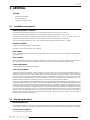
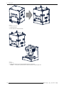
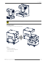
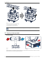
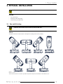
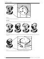
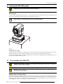
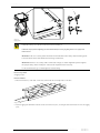

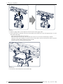
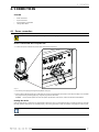
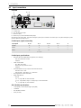
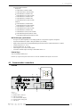


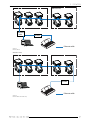

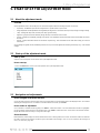

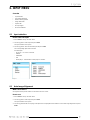
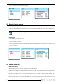
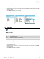
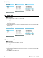


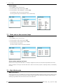
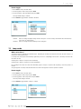
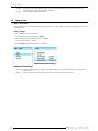
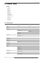
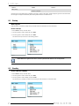
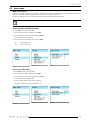
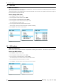
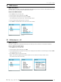
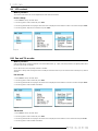
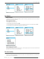
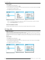
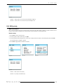

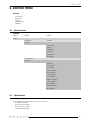
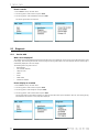
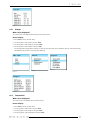

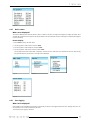
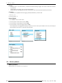
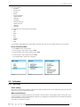
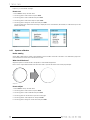
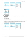

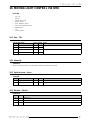
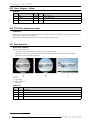

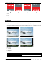
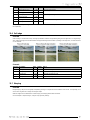
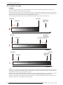
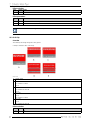
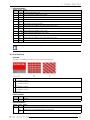
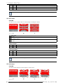
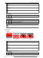
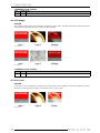
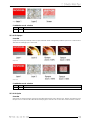
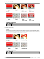
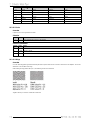
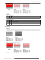
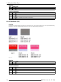
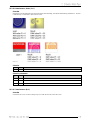
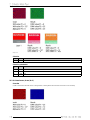
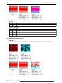
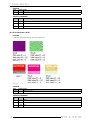
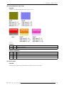
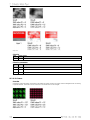
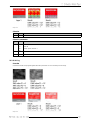
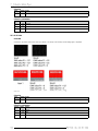
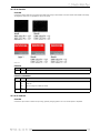


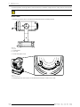
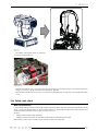
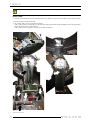


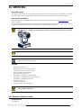
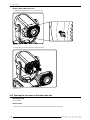
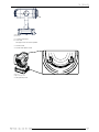
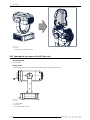
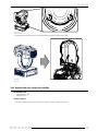
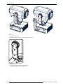
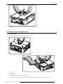
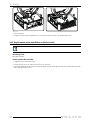
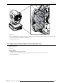
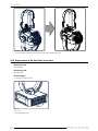
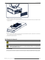

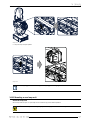
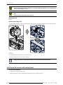
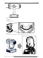
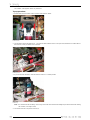
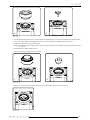

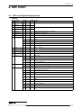
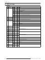
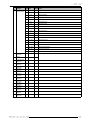
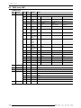

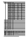
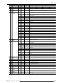
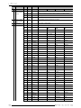
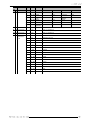

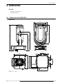
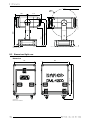
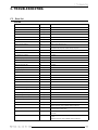
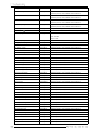
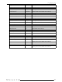

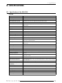


![DML-1200 [v04]](http://vs1.manualzilla.com/store/data/005824987_1-7e9516eac06e792a0e8f27802b417a45-150x150.png)