1
LeCroy WaveStation
LW4001LW400ASeries AWG
Remote Programmer’s Manual
August1996
Rev. C
LeCroy
CorporateHeadquarters
700 Chestnut
RidgeRoad
ChestnutRidge,NY10977-6499
Tel: (914) 578-6020,
FAX:578-5985
EuropeanHeadquarters
Mannheimerstrasse
175
D-69123Heidelberg,Germany
Tel: (49) 6221840989
FAX:(49) 6221833827
EuropeanManufacturing
2, rueduPr6-de-la-Fontaine
P.O.Box341
1217Meyrin1/Geneva,
Switzerland
Tel: (41) 22 71921 11, FAX:22 78239
Copyright
August
1996,LeCroy.
All dghtsreserved.
Information
in this publicationsupersedes
all earlier versions.
Specifications
subjectto change.
LeCroy®
Is a registeredtrademarkof LeCroyCorporation
WaveStation®
is a registered trademarkof LeCroyCorporation
Centronics®
is a registered trademarkof DataComputer
Corp.
Citizen®is a registeredtrademark
of Citizen AmericaCorp.
Epson®
is a registered trademarkof EpsonAmedca
Inc.
TM is a trademark
Hewlett-Packard®
is a registeredtrademark,andHP
of Hewlett-Packard,
Co.
r", PC/AT
TM andPSI2
TM are trademarks
IBM®
is a registered trademark,andIBMPC/XT
of International
BusinessMachines
Corporation.
MATHCAD®
is a registered trademark of MATHSOFT
INC.
MATLAB®
is a registered trademark of MATHWORKS
PSPICE®
is a registered trademarkof MICROSIM
Corporation
SmartTriggerTM is a trademarkof LeCroyCorporation
Microsoft®, MS-DOS®,
QuickBasic®,Excel®and Windows®
are trademarksof Microsoft Corporation.
PCX
is a file formatdeveloped
by ZSoft Corporationfor usewith PCPaint programs.
BubbleJet®is a registeredtrademark
of Canon
USA,Incorporated.
Apple®andMacintosh®
are registered trademarksof AppleComputer,Incorporated.
TABLE OF CONTENTS I
SECTION1
GENERALINFORMATION
InitialInspection
.............................................................................. 1-1
Warranty
.........................................................................................1-1
Product
Assistance
.......................................................................... 1-1
Maintenance
Agreements
................................................................
1-2
Service
Procedure
........................................................................... 1-2
Return
Procedure
............................................................................ 1-2
How
to Use
ThisManual
.................................................................
1-3
Introduction
.....................................................................................1-5
What
is SCPI
................................................................................... 1-5
SECTION2
ABOUTREMOTECONTROL
InterfaceConfiguration
andSpecialCommands
.............................
2-1
GPIB
Remote
Control
......................................................................
2-1
GPIB
Signals
and
Lines
..................................................................
2-1
Setting
theGPIB
Address
...............................................................
2-1
2-2
GPIBRemote
ControlandHardcopy
Operation
..............................
Remote
ControlOperation
overGPIB
.............................................
2-2
End
orIdentity(EOI)
Operation
.......................................................
2-2
Hardcopy
Operation
overGPIB
.......................................................
2-2
IEEE-488
Standard
Messages
........................................................
2-3
CheckingGPIBCommunications
Using National
Instruments
IBICProgram
.............................................................
2-5
Error
Code
.......................................................................................2-7
SECTION3
INSTRUMENTMODELAND SUBSYSTEMHIERARCHY
Remote
Command
System
Model
...................................................
Introduction
to SCPI
Command
Syntax
...........................................
Command
Subsystems
...................................................................
Overview
of OUTPut
Commands
....................................................
Overview
of WAVE
Commands
.......................................................
Overview
of FGEN
Commands
.....................................................
Overview
of EQUation
Commands
................................................
Overview
of DISPlay
Commands
..................................................
Overview
of HCOPy
Commands
...................................................
3-1
3-1
3-4
3-5
3-5
3-11
3-14
3-15
3-17
TABLE OF CONTENTS
Overview
of TRIGger
Commands
.................................................
Overview
of MMEMory
Commands
...............................................
Overview
of PROJect
Commands
.................................................
Overview
of SYSTem
Commands
.................................................
Overview
of STATus
Commands
.................................................
488.2
Command
Commands
.........................................................
3-18
3-19
3-20
3-21
.3-22
3-23
SECTION4
STATUS& ERRORREPORTING
Status
Register
................................................................................ 4-1
4-1
StatusByteOperation
.... . ................................................................
Status
Data
Structures
.................................................................... 4-1
Querying
the OperationalandQuestionable
StatusRegister.......... 4-3
Event
Enable
Registers
................................................................... 4-4
4-6
Status
Byte
Register
Definition
........................................................
4-12
Checking
StatusandRequesting
Service
.....................................
4-15
GPIB
Service
Request
..................................................................
SECTION5
WAVEFORM
TRANSFERSVIA GPIB
Introduction
.....................................................................................5-1
Transferring
Waveforms
via GPIB
..................
. ................................
5-1
5-2
TheData
Interchange
Format
(DIF)................................................
5-5
Viewing
Waveform
Datain theDIFFile ...........................................
Other
Data
Formats
........................................................................ 5-8
SECTION6
REMOTE
COMMANDS
.......................................................................
6-1
SECTION7
REMOTE PROGRAMMING
EXAMPLES
Introduction
.....................................................................................7-1
Setting Upthe Environment
for
7-1
QuickBASIC
Programming
............................................................
7-2
TheLWGPIB.BAS
Program
............................................................
7-9
End
OrIdentify(EOI)Operation
......................................................
7-9
Initializing GPIB
Communication
withtheAWG
...............................
7-9
Sending
a Command
to the LW400
SeriesAWG
............................
I TABLE
OFCONTENTS
Sendinga Query, Readingthe Response,and
UsingStatusto Determine
When
the Operationis Done...............
Downloading
aWaveform
.............................................................
Uploading
a Waveform
DIFFile to theAWG
.................................
INDEX
INDEX OF REMOTECOMMANDS
7-10
7-11
7-12
I
I TABLEOF CONTENTS
THIS PAGELEFT INTENTIONALLYBLANK
INITIAL INSPECTION
It is recommended
that the shipment
be thoroughlyinspected
immediately
upondeliveryto the purchaser.
All materialin the
containershouldbe checked
againstthe enclosedPackingList.
LeCroycannotacceptresponsibilityfor shortagesin comparison
with the Packing
List unlessnotified promptly.If the shipment
is
damaged
in anyway, pleasecontact the Customer
Service
Department.
WARRANTY
LeCroy
warrantsits productsto operatewithinspecifications
undernormalusefor a periodof oneyearfromthe dateof
shipment.Spares,replacement
parts andrepairs are warranted
for 90 days.Theinstrument’sfirmwareis thoroughlytestedand
thoughtto befunctional,but is supplied
"as is" with nowarranty
of anykind coveringdetailedperformance.
Productsnot
manufactured
by LeCroyare coveredsolely by the warrantyof
the original equipment
manufacturer.
In exercising
this warranty,
LeCroy
will repairor, at its option,replace anyproductreturnedto the Customer
ServiceDepartment
or anauthorized
servicefacility withinthe warranty
period,
providedthat the warrantor’sexamination
disclosesthat the
productis defectivedueto workmanship
or materialsandthat
the defecthasnot beencausedby misuse,neglect,accidentor
abnormal
conditionsor operation.
Thepurchaseris responsiblefor transportationandinsurance
charges
for the retumof productsto the servicingfacility. LeCroy
will returnall in-warranty
products
with transportation
prepaid.
Thiswarrantyis in lieu of all otherwarranties,expressed
or implied, includingbut not limited to anyimpliedwarrantyof merchantability, fitness, or adequacy
for anyparticular purpose
or
use.LeCroy
shall not beliable for anyspecial,incidental,or consequentialdamages,
whetherin contractor otherwise.
PRODUCTASSISTANCE
Answers
to questions
concerning
installation, calibration,and
useof LeCroyequipment
are available fromthe Customer
ServiceDept., 700ChestnutRidgeRoad,ChestnutRidge,New
York10977-6499,
U.S.A.,tel. (914)578-6020.
1-1
GENERAL INFORMATION
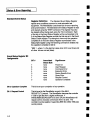
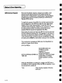
MAINTENANCE
AGREEMENTS
LeCroy
offers a selectionof customer
supportservices.Maintenanceagreements
provideextendedwarrantyandallow the
customer
to budgetmaintenance
costsafter the initial oneyear
warrantyhasexpired.Otherservicessuchas installation,
training, enhancements
andon-siterepair are availablethrough
specific Supplemental
SupportAgreements.
UPDATEDMANUALS
LeCroy
is committed
to providingstate-of-the-artinstrumentation
andis continuallyrefining andimproving
the performance
of its
products.Whilephysicalmodificationscanbe implemented
quite rapidly, the correcteddocumentation
frequentlyrequires
moretimeto produce.Consequently,
this manualmaynot agree
in everydetail with the accompanying
product.Theremaybe
small discrepancies
in the valuesof components
for the
purposes
of pulseshape,timing,offset, etc., andoccasionally,
minorlogic changes.
Where
anysuchinconsistencies
exist,
pleasebeassured
that the unit is correctandincorporates
the
mostup-to-datecircuitry. In a similar waythe firmware
may
undergo
revisionwhenthe instrument
is serviced.Shouldthis be
the case,manual
updateswill be made
availableas necessary.
SERVICE PROCEDURE
Productsrequiring maintenance
shouldbe retumedto the
Customer
ServiceDepartment
or authorizedservicefacility.
LeCroy
will repair or replaceanyproductunderwarrantyat no
charge.Thecustomer
is responsiblefor transportationcharges
to the factory.All in-warranty
products
will bereturned
to the
customer
with transportationprepaid.
For all LeCroyproductsin needof repair after the warranty
period, the customermustprovide a PurchaseOrderNumber
beforerepairscanbe initiated. Thecustomer
will bebilled for
partsandlaborfor therepair,as wellas for shipping.
1-2
Introduction
RETURNPROCEDURE
GENERAL INFORMATION
Todetermine
yournearestauthorized
servicefacility, contactthe
Customer
ServiceDepartment
or yourfield office. All products
retumed
for repairshouldbeidentified by the modelandserial
numbers
andincludea descriptionof the defector failure, name
andphonenumber
of the user, and, in the caseof products
returnedto the factory, a Retum
AuthorizationNumber
(RAN).
TheRANmaybe obtainedby contactingthe Customer
Service
Department
in NewYork,tel. (914)578-6020.
Returnshipments
shouldbe made
prepaid.LeCroywill not acceptC.O.D.or
Collect ReturnShipments.
Wherever
possible,the original
shippingcartonshouldbeused.If a substitutecartonis used,it
shouldberigid andbe packed
suchthat the productis
surrounded
with a minimum
of four inchesof excelsioror similar
shock-absorbing
material.In addressing
the shipment,
it is
importantthat the ReturnAuthorizationNumber
be displayedon
the outsideof the containerto ensure
its prompt
routingto the
properdepartment
within LeCroy.
explainsthe programming
protocolfor controlling
HOWTO USE THIS MANUAL Thismanual
the LW400/LW400A
Series Arbitrary Waveform
Generators,
including the LW420,LW420A,
LW410
and LW410A,
from a
host computer.Thesemodelsmayalso be reffered to as the
WaveStation.
Puposeof this manual:
Gainan overviewof the instrumentremoteprogramming
interface.
Familiarizeyourself with the SCPIprogramming
language
as
it applies to the LW400/LW40OA.
Providedetailedinformationonall of the WaveStation
remote commands.
1-3
GENERAL INFORMATION
Thefollowingsectionsarecontained
in this manual:
SectionI
Introduction
Givesa brief history of remote
controlinterfacesandprotocols
andexplains the advantages
of the SCPIcommand
language
andhowit is usedin the WaveStation.
Section 2
About RemoteControl
Explainshowto operatethe WaveStation
remotelyacrossthe
GPIBbus.
Section 3
Instrument Model and SubsystemHierarchy
Presents
the functionrepresentation
of the instrumentas viewed
fromthe remote
controlinterface,often referredto as the
instrumentModel.Describesthe command
hierarchy and
introducesbasicSCPIsyntaxandsubsystems.
Providesan
overviewof the command
hierarchyandhowit relates to the
arbitrary waveform
generator
functionalsections.
Section 4
Statue and Error Reporting
Describes
in detail the StatusandErrorreportingsystem.
Section 5
WaveformTransfers via GPIB
Explainsthe formatfor transferring waveforms
between
an
extemal device and the WAVESTATION
via GPIB.
Section 6
Remote Commands
Providesa detailed command
reference, including command
syntaxandpurpose.
Section 7
Remote Programming Example
1-4
Introduction
GENERAL INFORMATION
Introduction
Theremotecontrol interface consists of hardware,the GPIB
port, as well as a softwareprotocol.Thehardware
interfacesare
describedin your user manual
for the instrument.Thesoftware
protocolis describedin this manual
andbuilds uponthe rapidly
emergingindustry standard SCPI(Standard Commands
For
Programmable
Instruments).
Whatis SCPI
SCPIis a remotecommand
languagefor test and
measurement
instruments.It wasdeveloped
by a consortiumof
test andmeasurement
instrumentmanufacturers
andis
intendedto providea consistentprogramming
language
for
instrument
controlanddatatransfer.
IEEE-488
(GPIB)wasadoptedas a standardremotecontrol
interfacein 1975.Thestandardspecifiedsystem
interconnectionsandcommunication
protocolswhichprovideda
universalhardware
interfacefor integratingmultipleinstruments
into a test system.Theoriginal standard
put instruments
ona
common
bus, but eachinstrumentmanufacturer
useda
proprietary command
set. Everytime a user addeda new
instrument
to the bus,hehadto leamanotherset of, often
enigmatic,commands.
Updates
to the standardin 1987,led to
IEEE-488.1
and488.2whichfurtherrefinedthe standard
but still
fell short of ensuringa common
command
syntaxbeyonda few
mandated
"common
commands".
In 1990, the Standard
Commands
for Programmable
Instruments(SCPI)consortium
developeda systemof common
remotecommands.
AlthoughSCPIwasoriginally definedfor GPIB,it hasnow
spreadwell beyond
that interfaceandis beingusedto supporta
widerangeof hardware
interfaces. For example
SCPIhas
became
a majorelementin the implementation
of VXl based
systems.
The SCPIcommand
languagestandardizes command
syntax
andstructureusedin remotecontrol of test andmeasurement
instrumentation
andis beingrapidly adopted
by leadersin test &
measurement
instrumentation.Thisallowsthe user to learn a
single set of remotecommands
for instrumentswhichare
suppliedby different manufacturers.
Because
the functionalityof
instrumentscanvary widely, andbecause
newinstrumentsand
measurement
techniquesare constantlybeingdeveloped,the
SCPIstandardmakesprovision for newcommands
to be added
1-5
GENERALINFORMATION
as needed.Because
LW400
hasmanyuniquefeatures (for
example,waveform
formats), LeCroyhasenhanced
the SCPI
language
to provideaccessto theseadvanced
capabilities.
SCPIbenefitsthe userby providinga single command
set for
integratingmultipleinstruments
into a test system.
Thegreatest
benefit occursonthe secondor subsequent
systemintegration
programs,wherethe user doesnot leamyet anothercommand
language.
Thismanual
will provideyouwith all the informationyourequire
to control your LW400
using the SCPIprogramming
language.
Because
SCPIis an industrystandardandnot specific to
LeCroy,
detailson the genericstandard
areavailablein industry
standardSCPImanuals.
1-6
I ABOUTREMOTECONTROLI
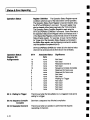
2
TheWaveStationcan be operatedremotely from an instrument
Interface Configuration
and Special Commands controller or computeracross the GPIBbus and commands
sent over GPIBcanset or read anyWaveStation
front panel
instruction.
GPIB RemoteControl
TheGPIBbuscaninterconnectmanyinstrumentsto allow
communication
with oneanotherover sharedcables. TheGPIBbus
usesa bit-parallel, byte-serialformat.A deviceconnected
to the
GPIB
is either a talker, listener, or controller.Although
some
devicescanchange
roles, a devicecanperformjust onerole at a
time.
Talker
Placesmessages
or data on the GPIBbus for
transmissionto other devices.Only onedeviceon
the networkcanbe the talker.
Listener
Receivesdata or commands
over the bus. Several
listeners maybe active at onetime.
Controller
Governs
the operationof the bus.A controller, usuallya computer,
normallysendsprogrammessages
to devicesandreceives
responses
fromthem.Onecontroller task is to decidewhichdevice
is the talker andwhichis a listener(s). Thecontrollermayassign
itself to bethetalkerat onetime,anda listenerat othertimes.If
deviceson the busneverchange
their roles, a controlleris not
required.
GPIBSignals and Lines
TheGPIBbushas16signal lines andeight groundlines. Eightof
the 16signallines forma bi-directionaldatabuswhichtransfersdata
andcommands.
Theremainingeight signal lines control the bus
operation.Threelines are for handshaking
signalswhich
synchronize
datatransmission.Theremaining
five lines are
management
lines whichcontrol the flow of informationacrossthe
busandtakespecialaction.
accessed
Setting the GPIBAddress TheGPIBaddressis set in the SystemSub-menu,
throughthe Project andPreference
menu.Fromthe front panel
pressthe Projectkey. Pressthe soft keysadjacentto the
Preferences
andthen systementries on the menus
to enter the
systemmenu.Pressthe soft keyadjacentto the GPIBentry on the
2-1
ABOUT REMOTE CONTROL
menu
to enter the GPIBsetupmenu.Turnthe rotary to select the
GPIBaddress.
Thefactory default setting for the GPIBaddressis 1.
GPIB RemoteControl and
HardcopyOperation
TheWaveStation
cancommunicate
acrossthe GPIBbusas a talker
or as a listener with a remote
hostcontroller(computer).
Forthis
talker/listener remotecontroloperation,the WaveStation
conforms
to
the guidelinesspecifiedby IEEE488.Thehardcopy
outputcanalso
communicate
acrossGPIBin oneof twoways.First, if the hardcopy
port is the same
as the remotecontrolport, thena remotehardcopy
command
sendsthe output to the remotehost as a queryresponse.
Second,
if the hardcopy
port is differentfromthe remote
controlport
or the local hardcopy
keyis pressed(Hardcopy
Execute),thenthe
WaveStation
enters talk only mode
anddoesnot expectany
controllerpresentonthe bus.
RemoteControl Operation
over GPIB
Talk/Listen
Endor Identify(EOI)
Operation
TheWaveStation
enters this modewhenever
a command
is
receivedvia the GPIBbus.In this mode,the Wavestation
canboth
receive commands
andsetupsfrom the remotehost computer
(controller) andsenddata andmeasurement
results.
Exceptwherespecifically noted,all commands
to andfromthe
WaveStation
areterminatedby assertingthe EOIsignalline
simultaneously
with the last bytetransmitted.Noother command
terminators
arerequired.
HardcopyOperation over GPIB
Talk Only
2-2
TheWaveStation
enters this modewhenever
the hardcopy
destinationis set to GPIBandthe Hardcopy
Execute
soft keyis
pressed.Talk only is a specialGPIBmode
wherethere is no
controllerallowedon the bus;the WaveStation
is the onlytalker and
all connected
devicesmustbelisteners(i.e., printers/plottersmustbe
in ListenOnlymode).
II
Talk/Listen
ABOUTREMOTE
CONTROL
If hardcopydestinationis GPIBandthen sendingthe HCOPy
command
over the GPIBbuswill causethe WaveStation
to sendthe
hardcopyoutput to the host computer
as a responsemessage.
In
this mode,
the WaveStation
will wait to be addressed
to talk before
sendingthe hardcopydata. Thehost computer
then hasthree
optionsin generating
the hardcopy:
mayreadthe data into internal memory
and
1) Thehost computer
thensendthedatato a printer/plotter.
remotecommand
and
2) Thehost computermaysendthe HCOPy
thenaddress
the printer to listener andthe WaveStation
to talk
andreadthe datafromthe WaveStation.
Asthe data is readinto
thecomputer,
it is alsoprintedto the printerwhichis a listener.
remotecommand
and
3) Thehost computermaysendthe HCOPy
thenaddress
the printer/plotterto listen, the WaveStation
to talk,
andthe controllerto go into stand-bymode
waitingfor EOI.
IEEE-488 Standard
Messages
SerialPoll Function
Receiving
the Trigger
Message
InterfaceClear
This sectionexplainshowthe WaveStation
reactsto the Standard
488.2 messages.
TheWaveStation
implements
a full Serial Poll InterfaceFunction:
1. It canassertthe SRQ
(ServiceRequest)
controlline.
with the currentserial poll byteor STBwhen
2. It will respond
addressed
to Talkandafter the Serial Poll Enable
interface
message
is received.
the WaveStation
stops
3. After transmittingits statusmessage,
assertingthe SRQ
line andclearsits intemalstatusbyte.
TheWaveStation
respondsto the Trigger message
[*’I’RG
command]
by triggeringthe outputwaveform.
It is executed
after all
previously receivedcommands
havebeenprocessed.
TheInterfaceClearmessage
(assertingIFCline) is an asynchronous
controlline that causes
all busactivity to halt. When
the WaveStation
receivesthe IFCmessage,
it becomes
unaddressed,
stops talking or
listening,andwill notparticipatein futurebustransactions
until
readdressed
to talk or listen.
2-3
~4BOUT
REMOTE CONTROL
DeviceClear
(Selectiveor Universal)
Goto Local,Goto
Remote,Goto
Remotewith Lockout
Local
TheWaveStation
will respond
to a SelectiveDeviceClearor a
UniversalDeviceClearinterfacemessage.
Theformerrequiresthat
the WaveStation
first beaddressed
to listen, followedby the
SelectiveDeviceClearmessage.
Thelatter doesnot requirethat the
instrumentbe previouslyaddressed
to listen. DeviceClearcauses
the input buffer, the outputqueue,andthe message
available(MAV)
statusbit to becleared.
TheWaveStation
canoperatein Localor Remote
mode.In Local
mode,
all front panelcontrolsare operationalandcommands
from
the hostcomputer
will also be processed.
In Remote
mode,the
WaveStation
operatesundercomputer
control andno front panel
controlsareoperational
exceptthe Localsoft key(if enabled).
The
WaveStation
alwayspowerson in Local mode).
Note: TheWaveStation
processesall messages
regardlessof
being in Remote
or Local modes.
TheWaveStation
switches to Remote
mode(with Local soft key
enabled)whenthe WaveStationreceives a command
with the
RENline asserted.All instrumentsettings remainunchanged
during local-to-remotetransitions. TheWaveStation
screen
indicates that Remote
modeis enabledby the appearance
of the
Localsoft key. Noother front panelcontrolsoperate.
If the WaveStation
is underremotecontrol andthe Local soft key
is pressed,the instrumentinterrupts program
control andreturns
to local control. Dataand/orsettings cannotbechanged
locally.
Caution:.In LocalLockoutstate, all front panelkeysandknobs
are disabled. OnceRemote
with Local Lockoutis set using the
"RWLS"
or "LLO"commands
it can only be cleared whenthe
WaveStation
is put into Local modeby sendingthe "LOC"
command
or readdressing the WaveStationwith REN
deasserted.
2-4
I
Checking GPIB
CommunicationsUsing
National InstrumentsIBIC
Program
ABOUTREMOTECONTROLI
Thisquickcheckoutrequiresa computer
with a NationalInstrument
GPIBcard andthe NationalInstrumentsIBIC program
suppliedby
NationalInstrumentswith the purchase
of a GPIBcard. This quick
checkout
also assumes
that the GPIBcardis alreadyinstalled in the
computer
andhaspassed
all test successfully.Forhelpinstalling or
configuringthe NationalInstruments
GPIBcard pleasecontact
NationalInstruments
at (800)IEEE-488
or (512)794-0100.
Theseexampleinstructions are for an IBM-PC
or compatible
computer.Themethodfor other computers
is very similar.
Change
to the National InstrumentsGPIB-PC
subdirectory with
the command:
CD \GPIB-PC
Start the IBIC programby with the command:
IBIC
Tell the IBIC programthe addressof the WaveStation
(we
assumeaddress1) with the command:
IBFIND DEV1
Send the identify
command:
commandto the WaveStation with the
IBWRT"*IDN?"
Readthe id of the WaveStation
with the command:
IBRD 100
2-5
IABOUT REMOTE CONTROL
I
TheWaveStation
response
shouldhaveincludedthe model
number,
serial number
andotherinformation.
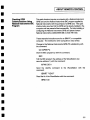
Thefull IBIC
sequence
shouldlook as follows:
National Imstruments Interface BUS
Interactive Control Program (IBIC)
Type ’ help ! for help.
: IBFIND DEVI ,
devl: IBWRT ’~* IDN?"
( cmpl
[0100]
count: 55
devl: IBRD 100
[2100]
( end cmpl )
count: 31
4C 65 43 72 6F 79 2C 4C
57 34 30 302c4c5734
32 302f 55 31 3030 30
2C31 2e34 2e32 0a
L
W
2
,
e C r o y , L
4 0 0.
L W 4
0 / U 1 0 0 0
1 , 4 . 2 .
If IBIC retumed
anerror on anyof the commands,
doublecheck
to makesureyoutypedthe command
exactly as givenabove,
thenconsultthe NationalInstruments
GPIB-PC
manual
for help
interpretingthe errorcodes.Abrief list of some
of the common
errorsandpossible
solutions
follows:
2-6
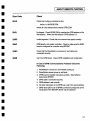
I
ABOUT REMOTECONTROL I
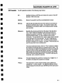
Error Code
Check
EDVR
Check
that config.syscontainsthe line:
device= c:\dirkGPIB.COM
wheredir is the directorythat containsGPIB.COM.
ENOL
Nolistener. CheckIBFINDDEVxmatches
the GPIBaddressof the
WaveStation.Wherethe WaveStation
GPIBaddressis x.
EARG
Invalid argument.
Checkthat the command
wastypedcorrectly.
ESAC
GPIBboardis not systemcontroller. Checkto makesure the GPIB
boardis configuredas controller usingIBCONF.
EABO
Checkthat the WaveStation
is powered
on andcablesare
connected
securely.
ENEB
Can’tfind GPIBboard.Check
GPIBinstallation andconfiguration.
In Case of GPIBCommunications
ProblemsCheckthe
Following:
1. WaveStation
is tumedon, andfinished bootingup.
2. WaveStation
passespowerup self tests.
all tests. (SeeNational
3. GPIBboardis installed andpasses
InstrumentsIBTEST).
4. GPIBcable is connected
securely.
addressis set correctly.
5. GPIB
6. Noother instrumenton the GPIBbusis set to the same
address.
7. GPIBname(DEV1)set in IBFINDcommand
correspondsto the
name
given in the IBCONF
devicemapfor address1.
2-7
4BOUT REMOTECONTROL
~
Thispageleft intentionally blank
2--8
I
3
¯1
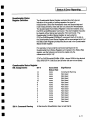
Remote Command
SystemModel
INSTRUMENT MODEL AND
I SUBSYSTEM
HIERARCHY
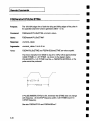
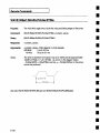
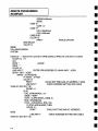
It is importantto understand
the remotecontrol subsystem
hierarchyin order to rapidly locate the desiredcommand
and associatedmessage
you require. Figure 1 showsthe
functional block diagramof the arbitrary waveform
generatoras viewedby the remoteprogramming
interface.
Thestructure of the instrumentsubsystems
is closely
related to this blockdiagram.
FGENera±or
PROJect
MMEMory
> BUTPu±
I>
4,
TRIGger
EQUation
f
I
]]ISPtay
I
HCIqpy
FigureI
Introductionto SCPI
Command
Syntax
SCPIcommands
are EnglishlanguagebasedASCIItext strings.
TheSCPIcommand
set is basedon a hierarchical modelof a
genericinstrument.Theinstrumentis brokendowninto major
systemelementslike OUTPUT,
DISPLAY,
etc. Thecommand
follows a pathfrommajorfunctionalelements
downthrough
3-1
’Instrument
Modeland
Subsystem
l-llerarchy
subsystems,
to specific functionswithin the subsystem.
For
example
to turn on Channel
l°s 1 MHz
outputbandwidth
limit
filter the command
wouldbe:
OUTPutl:FILTer: FREQuency
1E6
Thecommand
is shown
in its long(or verbose)form.Aswith all
commands
describedin this manual,the uppemase
letters
indicatethe characters
requiredto represent
the shortformof
the command.
Notethat SCPIinstrumentsare not case
sensitive,the useof capitalizationin this manual
is onlyintended
to showthe differencebetween
the longandshort formsof the
command.
Notealsothat the short formandlongformare the only
acceptableformsof a command.
So, for "frequency"wecan
send"freq" or "frequency"
but not "frequ", for example.
The
shortformis thefirst fourletters, unless
thefourthis a vowel,in
whichcasetheshortformis thefirst threeletters.
Keywords
are separatedby colons, while arguments
usea
spaceas a delimiter. Multiple commands
canbe includedin a
single multi-elementcommand
by using a semi-colonto
separateeachelement.Multiple elements
within the same
command
maybe abbreviatedif eachelementis within the
samesubsystem.
Thesecondelementin a multi-element
command
mustbepreceded
with a colonif it is not withinthe
samesubsystem.Commands
enclosedin squarebrackets
indicate default subsystems.
For example,OUTPutl:STAte
ON
is equivalentto OUTPut1
ON.
3-2
Instrument Model and
Subsystem Hierarchy
I
I
Theseare four valid WaveStation
commands
undertwo different
subsystems. The WAVE
and OUTPutsubsystems.
WAVE:SELECT
chl - Enable channel 1 editor
WAVE:OPEN
"new_wave"- Select waveformnew_wave
OUTPut1
:FILTer:FREQuency
1 E6 - Enablesthe Channel1
MHzBandwidthfilter
OUTPut1
on - Enableschannel1 output
Theabovecommands
maybe sent to the WaveStationone
command
at a time or theymaybecombined
into a single multielementcommand.
Followingare valid formsfor a multi-element
command.
Eachelementin the command
is separatedby semicolon.
WAVE:SELECT
chl ;OPEN"new_wave"
OUTPut1:FILTer:FREQuency1E6;:OUTPutlon
Notethat whencommands
are combined
using the semicolon
they mustbe at the samelevel in the command
hierarchy. So
the second
line, in the example
above,cannotcontainjust the
argument
"on", it requiresthat the keyword
:OUTPut1
be
included.Analternative formof the combined
command
places
the commands
in hierarchicalorderanddoesn’trequirea restatementof the keyword:
OUTPut1on; FILTer:FREQuency
1E6
A completediscussionof SCPIcommand
structure is contained
in "SCPI1993,Volume
1:SyntaxandStyle" availablefromthe
SCPIConsortium.
TheEnglishnature of SCPIcommands
often meansthat a
command
candirectly be mapped
to a correspondingmenu
control. Where
standardcommands
are not availablein the
1993SCPIstandard,LeCroyhasextendedthe languageto
facilitate controlof the instrument.
Extensions
to the language
use command
namesand arguments
that adhereto the
terminologyusedin the menu
systemwhereverpossible.
3-3
I
Instrument Model and
Subsystem Hierarchy
overviewof the SCPI
Command
Subsystems This sectionprovidesa comprehensive
command
subsystems.All command
keywordsare shown.This
sectionis intended
to assisttheuserin rapidlylocatingthe
command
formrequired to carry out AWG
actionsor query
settings andvalues.Commands
with only a queryformare
shown
with a ’?’ as a suffix. Command
arguments
are not
described
in detail in this section.Referto Section
6 of this
manual
for details of command
arguments
andfor additional
informationon the commands.
OUTPutSubsystem
3-4
TheOUTPut
subsystem
providescontrol of the output
channel(s),additivenoise,andlowpassfilter bandwidth
selections.
Because
the instrumentmayhavetwo channels,the OUTPut
subsystem
is controlled usingOUTPut1
or OUTPut2
in order to
uniquelycontroleachof the arbitrary waveform
generator’s
outputs.In this manual,
the numeric
suffix to the OUTPut
subsystem
is shown
in generalformusinga # characteri.e.,
OUTPut#:NOISe
controls the noiseoutputof either channel.
I
InstrumentModeland
Subsystem Hierarchy
I
I
Overviewof OUTPutCommands
OUTPut#
[STATe]
FILTer
[LPASs]
FREQuency
NOISe
[STATe]
LEVel
PATH
Enablesor disablesthe output for the specifiedchannel.
Setsthe bandwidth
for the specified channel.
Enablesor disablesthe addition of uncorrelated,pseudo
random
noise into the specified output channel.
Setsthe level of noisethat is insertedinto the waveform
for
the specifiedchannel.
INTERNAL
or EXTERNAL.
EXTERNAL
= routed through
BNC’son rear. Note: OUTPI
: NOISE:PATH
is functionally
coupledto OUTP2:NOISE:PA
TH. Both are either internal or
external
OUTPut2:RESample
Issues command
to resamplechannel2 waveform.This
command
only applies to channel2.
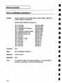
WAVESubsystem
TheWAVE
subsystem
controls the selection, creation,editing,
andmathematical
manipulationof waveforms
in the selected
waveform
editor, channel1, channel2, or scratchpad. The
operationof the WAVE
subsystem
is augmented
by the
FGENerator
and EQUation
subsystems
whichhandlethe
specializedoperationsassociated
with waveform
creation.
Overview of WAVEcommands
WAVE
AMPLitude
AMPLitude
MEDian
VMAX
VMIN
Setsthe peak-to-peakamplitudeof the region between
the
left andright timecursors.
Setsthe median
voltagelevel of the regionbetween
the left
andright timecursor.
Setsthe maximum
voltage of the region between
the left and
right timecursors.
Sets the minimum
voltageof the region between
the left and
right timecursors.
3-5
I
Instrument
Model and
SubsystemHierarchy
WAVE
CLOCk
DECade
FiXed
FREQuency
PREServe
ACSet
LIMit
MAX
WAVE
CUT
COPY
DELete
EXTRact
WAVE
DATA
PREamble
INSert
MODE
PASTe
[IMMediate]
COUNt
CURSor
WRAP
3-6
Selectsthe clock decade
in whichthe internal clock runs.
Selectswhetherthe clockis fixed or variable.
Setsthe frequencyof the clock.
POINTS
or TIME. Affects the operation of CLOCK:DECADE.
Preservepoints keepdata unchanged;
preservetime
resamples
to keepoutput timing the same,if possible.
Selects auto clock set modeor manual.
Selects/deselects
optionto limit clockto internalfilters.
With LIMit set to Yes,MAX
selects the clock decadein which
the internal clockruns.
Copiesthe region between
the right andleft time cursorsto
the cut buffer.
Deletes the data betweenthe left and right time cursors,
storesit to thecut buffer.
Copiesthe value of the waveformminusthe value of the
baselineto the cut buffer.
Transferwaveform
in DataInterchangeFormat(DIF) to
from host computer.
Transfer waveform
DIF preambleto or from host computer.
Selectsinsert or overwriteinsertion mode.
Inserts the contentsof the cut buffer into the waveform.
Setsthe insert repetition count,i.e, number
of timesthe
contentsof the cut buffer is insertedinto the waveform.
Selectsif waves
are insertedbeforeor after the cursor.
Selectsif waveform
is to be continuous
with the last point
wrapped
to first or if waveform
is singleshot.
I
Instrument Model and I
Subsystem Hierarchy
I
WAVE
INSert
SCOPe
[IMMediate]
ADDRess
BWLimit
CONTrol
PREServe
SOURce
TYPE
SHAPe
DC
DURation
LEVel
PULSe
AMPLitude
BASE
CYCLes
ETIMe
PERiod
TDELay
WIDTh
RAMP
AMPLitude
CYCLes
FREQuency
INVert
OFFSet
SPOSition
Downloads
the data fromthe specified digital oscilloscope
(DSO).
Sets the GPIBaddressof the sourceDSO.
Select option to check for and correct waveform
discontinuitiesor to not checkor correctdiscontinuities.
Selectsthe GPIBrequestcontrol modefor DSOtransfers.
Setshowthe data fromthe digital oscilloscopeis preserved.
Thedata canbe preservedin time or by points.
Selects waveform
sourcefrom available DSO
traces.
Selects DSOtype (model),
Set the timeduration(length) of the insertedDCfunction.
Set the voltagelevel of the insertedDCfunction.
Sets the baseto top amplitudeof the standardwavepulse.
Setsthe basevoltagelevel of the pulse.
Setsthe number
of pulse cycles inserted into the waveform.
The10%-90%
transition time of the rising andfalling edges
of the standardwavepulse.
Setsthe period (1/frequency)of the standardwavepulse.
Setstime delay from the beginningof the waveform
andthe
beginning
of the first edgeof the pulse.
Setsthe half amplitudewidthof the standardwavepulse.
Sets the peak-to-peakamplitudeof the standardwaveramp.
Sets the numberof cycles of the standardwaveramp
insertedinto the waveform.
Sets the frequencyof the standardwaveramp.
Controlsthe polarity of the ramp’sslope,i.e. rising or falling.
Setsthe voltageof the zero degreephaseof the ramp."
Setsthe start position of the rampin percentage
of the ramp
amplitude.
3-7
l
lnstrument
Modeland
Subsystem
l-llerarchy
WAVE
INSert
SHAPe
SELect
SINE
AMPLitude
CYCLes
FREQuency
OFFSet
PHASe
SQUare
AMPLitude
BASE
CYCLes
ETIMe
FREQuency
TDELay
TRiangle
AMPLitude
CYCLes
FREQuency
OFFSet
PHASe
3-8
Selectswhichstandardwaveshapewill be inserted into the
waveform.
Sets the peak-to-peak
amplitudeof the standardwavesine.
Setsthe numberof cycles of the standardwavesine to be
inserted into the waveform.
Setsthe frequencyof the standardwavesine.
Set the voltage of the zero degreephaseof the standard
wavesine.
Setsthe start phaseof the standardwavesine.
Setsthe baseto top amplitudeof the squarewave.
Setsthe voltageof the baselevel of the squarewave.
Setsthe number
of cyclesof the squarewavethat will be
insertedinto the waveform,
Setsthe 10%-90%
transition timeof the rising andfalling
edgesof the squarewave.
Sets the frequencyof the squarewave.
Sets the delay time between
the start of the waveform
and
the first edgeof the squarewave.
Setsthe peak-to-peak
amplitudeof the standardtriangle
wave.
Setsthe number
of cyclesof the triangle wavethat will be
insertedinto the waveform.
Setsthe frequencyof the triangle wave.
Setthe voltageof the baseof the triangle.
Phaseof the triangle wave.
[IMMediate]
Insertsthe specifiedshape
at the left timecursor.
WAVE
Insert the named
waveform
into the current waveform
at the
TIMELEF’r cursor.
I
WAVE
MARKer
CLOCk
FIRSt
FREQuency
EDGE
DEFault
NDEFined
TIME
[STATE]
LEVel
TYPE
Instrument Model and
Subsystem Hierarchy
Setsthe time at whichthe first edgeof the clock marker
begins. WAVE:MARKer:TYPE
must be set to CLOCk.
Setsthe frequencyof the markerclock.
WAVE:MARKer:TYPE
must be set to CLOCk."
Setsdefault edgemarker.
Queryonly. Number
of edgesdefined.
Setsthe time at whichSTATE
will act.
Lowor High.
Setsthe voltagelevel of the markerto TTLor ECLlevels.
Selectseither a clock markeror an edgemarker.
MATH
COUPling
IMMediate
SOURce2
[OPERation]
NEW
OPEN
REGion
LEFT
RIGHt
ACor DC,usedonly for INTEGRATION.
If DC,integration of
a constant non-zerovoltage becomes
a ramp.
Performsthe mathfunction specified by
WAVE:MATH[:OPERation]
on the current waveformand
WAVE:SOURce2
(if applicable) on the region betweenthe
left andright timecursors.Theresult is placedinto the
current waveform.
Name
of the "other" waveform
for two waveform
operations
such as ADD, SUBTRACT,
MULTIPLYDIVIDE.
Specifies whichmathoperationwill be performedby
WAVE:MATH
:lMMedate. Operation can be SMOOTH,
ADD,
SUBTract,MULTiply,DIVide, INTegrateDIFFerentiate
CONVolve.
Createsa newwaveform
with the namespecified by the
argument.
Opensa waveform
from the current project.
Setthe positionof the left timecursor.
Set the position of the right time cursor. This command
requirestimecursorsnot to be in the track mode.
3-9
Instrument Model and
SubsystemHierarchy
WAVE
SAVE
Savesthe current waveform
with the namesuppliedby the
argument.
SELect
Selects the active waveform
editor CH1,CH2,or SCR.
TIME
DELay
DURation
MODE
[TIME]
MOVE
SEQuence
ADVance
AON
COMPile
Data
GDATa
GLINk
GNEW
IREcall
ISAVe
JUMP
LINK
NEW
OPEN
SAVE
3-10
Delaysthe waveform
fromthe left cursorto the endof the
waveform
for the given amount
of time.
Selectsthe mode,insert or overwrite,for changing
the
durationof a feature.
Changes
the durationof the regionbetween
the left andright
time cursorsusing the duration changemodedefinedby the
duration modes.
Moves
the feature between
the left andright time cursors.
Advance
to the next sequence
in a groupsequence
list.
Specifies whichchanneladvanceand jumpoperateon.
Causethe desired sequence
to play.
Tansfersa sequence
file identified by a filenameto or from
the WaveStation
via GPIBin #0 blobk format.
Transfersa groupsequence
file to or from the AWG
via
GPIBin #0 blockformat.
Adda newsequence
to the endof the sequence
list in the
currently selectedgroupsequence.
Creates a newgroup sequence.
Recalla savedimagefile.
Savea binaryimageof the hardware
to a file.
Jump
to the nth sequence
in the list.
Addon entry to the endof the sequence
list in memory.
Emptythe sequence
list, associatea newnamewith
sequence
list.
Openandcompilea sequence
file fromthe project.
Savethe sequence
list frommemory
to the current project.
I
Instrument Model and
Subsystem Hierarchy
I
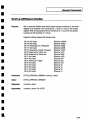
TheWaveStation’sstandardfunction generatormodeis
controlled by the FGENerator
subsystem.Anyof the seven
standardwaveforms,
sine, triangle, square,ramp,pulse,
multitone, and DCcan be specified. Keyparameterssuchas
frequency,amplitude,offset, andstart phasecanbe controlled
directly. Additionally,the frequency
of the sine, triangle, square,
rampandpulse waveforms
can be sweptlinearly or
logarithmically.
Overview of FGENCommands
FGENerator#
DC
Set the DCvoltagelevel for the specifiedchannel’sfunction
LEVel
generator(either I or 2).
MULTitone
Setsthe peak-to-peak
amplitudeof the multitonefunction in
AMPLitude
the specifiedchannel’sfunctiongenerator(either 1 or 2).
Setsthe number
of tonesto be calculatedfor the multitonefunction.
NTONes
Set the voltageof the zero degreephaseof the multitone
OFFSet
waveform.
TONE#
RAMPlitude
Setsthe relative amplitude
of the currenttonein the
multitone waveform.
[FREQuency]
Set the frequencyof the current tonein the multitone
waveform.
PULSe
Setsthe baseto top amplitudeof the pulsein the specified
AMPLitude
channel’sfunctiongenerator(either 1 or 2).
Setsthe voltageof the baselevel of the pulsewaveform
in
BASE
the specifiedchannel’sfunctiongenerator(either 1 or 2).
Setsthe 10%-90%
edgetime of both the rising andfalling
ETIMe
edgesof the pulse waveform.
Setsthe period(1/frequency)of the pulsein the specified
PERiod
channel’sfunctiongenerator(either 1 or 2).
SWEep
SPACing
Selectsthe typeof sweep
(either linear or log) in the
specifiedchannel’sfunctiongenerator(either 1 or 2).
STARt
Setsthe start frequencyof the sweep.
Sets the stop frequencyof the sweep.
STOP
Setsthe sweepduration.
TIME
Turns
the sweepon or off.
[STATe]
FGENeratorSubsystem
3-11
I
Instrument Modeland
SubsystemHierarchy
FGENerator#
PULSe
TDELay
WIDTh
RAMP
AMPLitude
FREQuency
INVert
OFFSet
SPOSition
SWEep
STARt
STOP
TIME
[STATe]
SELect
SINE
AMPLitude
FREQuency
OFFSet
PHASe
SWEep
SPACing
STARt
STOP
TIME
[STATe]
3-12
Sets the amount
of time between
the beginningof the
waveform
andthe beginningof the first edgeof the pulse.
Sets1hewidth of the pulse from50%up the rising edgeto
50%downthe falling edge.
Setsthe peak-to-peak
amplitudeof the rampin the specified
channel’sfunctiongenerator
(either 1 or 2).
Setsthe frequencyof the ramp.
Controlswhetherthe rampis rising or falling.
Set the medianvoltage of the rampwaveform.
Setsthe start positionof the rampin percentage
of the
ramp’speak-to-peakamplitude.
Setsthe start frequencyof the sweep.
Setsthe stop frequencyof the sweep.
Sets the sweepduration.
Turnsthe sweepon or off.
Selectswhichfunctionthe specifiedchannel’sfunction
generatoroutputs. Theavailable functions are: SINE,
TRiangle, SQUare,RAMP,PULSe,MULTitone,and DC.
Setsthe peak-to-peak
amplitudeof the sine wavein the
specifiedchannel’sfunctiongenerator(either 1 or 2).
Setsthe frequencyof the sine wave.
Setsthe voltageof the zero degreephaseof the sine
waveform.
Setsthe start phaseof the sine wave.
Selectsthe sweep
type(either linear or log).
Setsthe start frequencyof the sweep.
Setsthe stop frequencyof the sweep.
Sets the sweep
duration.
Turnsthe sweep
on or off.
I
FGENerator#
SQUare
AMPLitude
BASE
ETIMe
FREQuency
SWEep
SPACing
STARt
STOP
TIME
[STATe]
TDELay
TRiangle
AMPLitude
FREQuency
OFFSet
PHASe
SPACing
SWEep
STARt
STOP
TIME
[STATe]
[STATe]
InstrumentModel
and
Subsystem Hierarchy
I
Setsthe peak-to-peakamplitudeof the squarewavein the
specifiedchannel’sfunctiongenerator(either I or 2).
Setsthe voltageof the baselevel of the squarewave.
Setsthe 10%-90%
edgetime of both the rising andfalling
edgesof the squarewave.
Setsthe frequencyof the squarewave.
Selectsthe sweep
type(either linear or log).
Setsthe start frequencyof the sweep.
Setsthe stop frequencyof the sweep.
Setsthe sweepduration.
Turnsthe sweepon or off.
Setsthe amountof time between
the start of the waveform
andthe first edgeof the squarewave.Usefulin single trigger
mode;in continuousthis time lowersthe frequency.
Setsthe peak-to-peak
amplitudeof the triangle wavein the
specifiedchannel’sfunctiongenerator(either 1 or 2).
Setsthe frequencyof the triangle wave.
Setsthe medianvoltage of the triangle waveform.
Setsthe start phaseof the triangle wave.
Selectsthe sweep
type(either linear or log).
Setsthe start frequencyof the sweep.
Setsthe stop frequencyof the sweep.
Sets the sweepduration.
Turnsthe sweepon or off.
Turnsthe functiongeneratoron or off in the specified
channel
(either I or 2).
3-13
I
Instrument Model and
Subsystem, Hierarchy
EQUationSubsystem
Theequationsubsystem
is usedto enter, select, save,and
recall equations
whichdescribewaveforms
mathematically.
It is
also usedto calculate the waveform
samplevaluesbasedon
the equation.
Overviewof EQUationCommands
EQUation
CALCulate
DATA
DEFine
DURation
LINE
NEW
OPEN
SAVE
3-14
Calculatesthe currentlyspecifiedequationline for the preset
durationandinserts it into the currentwaveform
at the left
cursorposition usingthe currentinsert mode.
Transfersall the lines of the equationsheetas a "#0" block.
#0 is an indefinite lengthblockof dataterminatedwith EOI.
Definedin IEEE488.2.
Definesan equationfor the current equationline. The
equationline maybe up to 50 charactersin length andmust
be surrounded
by quotes.Valid functions are: SIN, COS,
SQRT,PULSE,STEP,LN, LOG,ABS,EXPand TAN. Valid
operators
are: +, -, *,/, (,), "","", = and^. Validvariable
namesare X1 throughX16. Valid arguments
are T, PI,
NOISE, and GNOISE.
Setsthe time spanover whichthe equationwill be
calculated.
Selectsan equationline fromthe currentequationsheet.
Createsa newequationsheet.
Opensan existing equationsheet.
Savesthe current equationsheet.
I
DISPlay Subsystem
InstrumentM°deland
~ [
Subsystem
HierarchyI
TheDISPlaysubsystem
controls the selection and
presentationof text, graphicsandwaveform
information.In
addition, the cursorsystemis controlledby this subsystem.
Overviewof DiSPlay Commands
DISPlay
ANNotation
DATE[:STATe]
LOGO[:STATe]
PARameter[:STATe]
[ALL]
SSAVe
Allowsthe time/dateannotationfield to be switchedon or off.
Allowsthe Company
Logoto be switchedon or off.
Turnsthe parameters
readoutson or off.
For SCPIcompatibility. Same
as "Logo".
Allowsthe automaticscreensaverto be enabledor disabled.
[WINDow]
TRACe
ALL
COLor
Displaysthe wholewaveform
on the screen.
Setsthe trace intensity. Settingthe intensity for onetrace
will set the same
intensityfor all traces.
CURSors
TIME
DELTa
LEFT
RIGHt
SALL
Change
the delta time betweenthe time cursors. This
command
only haseffect if the cursorsare in the track mode.
Set the positionof the left timecursor.
Set the position of the right time cursor. This command
only
haseffect if the cursortrack mode
is off.
SelectAll selectsthe entire waveform
by placingthe left
cursorat timezeroandthe right cursorat the endof the
waveform.
Placesboth cursorsat the endof the waveform.
Movesboth time cursorsso they are on the display.
Enablesor disablestime cursortracking.
Turnsthe timecursorsonor off.
TEND
TGRid
TRACk
[STATe]
VOLTage
BOTTom Set the positionof the bottomvoltagecursor.
DELTa
Change
the delta voltage between
the voltage cursors. This
command
only haseffect if the voltagecursorsare in the
track mode.
Moves
both voltagecursorsso they are on the display.
TGRid
3-15
I
lnstrument
Modeland
Subsystem
Hierarchy
DISPlay
[WINDow]
TRACe
VOLTage
TOP
TRACk
[STATe]
GRATicule
COLor
GRID
[STATe]
TYPE
Setsthe position of the top voltage cursor. This command
onlyhaseffectif trackis off.
Enablesor disablesvoltagecursortracking.
Turnsthe voltagecursorson or off.
Setthe displayintensityfor the grid.
Selector querythe grid style. Thegrid maybea full grid
(ON),nogrid (OFF),or set to a crosshair (CHAir).
Selectsthe type of grid to display. Single, dual, SXY,XY.
TRACe
X[:SCALe]
CENTer Setsthe timeat the horizontalcenterof the grid.
PDIVision Setsthe horizontaltimeperdivisionof the grid.
TCURsors Displaysthe portion of the waveform
between
the time
cursorswith the left cursoronedivision fromthe left edgeof
the grid andthe right cursoronedivision fromthe right edge
of thegrid.
Y[:SCALe]
PDIVision Setsthevertical volts perdivisionof the grid.
RLEVel Setsthe voltageat the vertical centerof the grid.
ZPRevious
3-16
Restoresthe zoomsettings to the previoustime andvoltage
zoomsettings.
I
HCOPySubsystem
Instrument Model and I
Subsystem
Hierarchy
TheHCOpy
subsystem
provides control over printing and
output of screengraphicsformthe WaveStation.
Overview of HCOPyCommands
HCOPy
AUToincr
FILename
INDex
TARGet
GRAPhics
DESTination
FORMat
PRINter
DESTination
FFEed
MODel
QUALity
SIZE
TYPE
[IMMediate]
Enablesautomaticincrementof the filename index whena
hardcopy
is storedto a file.
Set or querythe current hardcopyfile name.
Set the hardcopyfilename index number.Theindex may
rangefrom 0 to 999.
Set the destinationfor the hardcopy
graphicsfile.
Set the hardcopy
graphicsfile format.
Set the destinationof the hardcopyprinter data. The
destinationmaybe the GPIBor Centronicsport, or it maybe
the floppydisk drivewherea file in printer formatwill be
stored.
Set whethera formfeed is automaticallygeneratedfollowing
a hardcopy.
Set the specifiedprinter model.
Setthe print quality, draft or proof. Thissetting is not
availablefor all supported
printers.
Set the size of the hardcopy,notebook
or presentation.
Sets the hardcopyformat. Hardcopiesmaybe formatted to
providedatasuitablefor printersor graphicsfiles.
Begina hardcopy.
3-17
l
lnstrument
Modeland
Subsystem
l-llerarchy
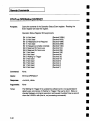
TRIGger Subsystem
Thetrigger subsystem
is usedto control the Triggersection
of the AWG.
Thisincludescontrols for triggering suchas
level, mode,sourceandslope.
Overviewof TRIGger Commends
INITiate [:IMMediate]
TRIGger[:SEQuence]
BCOunt
DELay
LEVel
MODE
SLOPe
SOURce
3-18
Triggers the system,equivalent to the IEEE488.2 command
*TRG.
Setsthe burst countor number
of repetitions of the waveform
that will beoutputafter a trigger is received
in burstmode.
Setsthe delayfromtrigger to start of outputof the waveform.
Setsthe triggerlevel in volts.
Sets the trigger mode.Thetrigger modemayset to
CONTinuous,
SINGle, BURSt,or GATE.
Setsthe trigger slope.
Setsthe trigger source.Thetrigger sourcemayinternal or
external.
InstrumentModel
and
Subsystem
Hierarchy
MMEMorySubsystem
The MMEMory
(mass memory)subsystemprovides support
for the extensiveharddisk storagecapability of the
WaveStation.
Overview of MMEMoryCommands
MMEMory
CATalog
EQUation
IMAGe?
SEQuence
WAVeform
[ALL]
DATA
PREamble
DELete
EQUation
IMAGe
PROJect
SEQuence
[WAVeform]
Returns
a list of all equations
in the currentproject.
Returns
a listing of imagefiles locatedin the currentproject
Retums
a list of all sequences
in the currentproject.
Returns
a list of all waveforms
in the currentproject.
Returns
a list of all objectsin the currentproject.
Uploador downloadthe waveformnamedin the associated
argument.Waveforms
are stored in DIF format.
Uploador downloadthe headerof the waveformnamed
in
the associatedargument.
Deletes the named
equation.
Deletes the namedimage.
Deletesthe named
project.
Deletes the namedsequence.
Deletes the namedwaveform.
3-19
I
Instrument
Model and
SubsystemHierarchy
PROJectSubsystem
Theproject subsystem
is usedto create, open,andsave
individualuser workareascalled projects.
Overview of PROJectCommands
PROJect
NEW
OPEN
SAVE
3-20
Createsa newproject with the specified name.Thecurrent
project is closedandthe newproject is created.
Opens
the specifiedprojectif it exists(noactionis takenif it
doesn’texist) andclosescurrentproject.
Savesthe currentproject.
I
SYSTemSubsystem
Instrument Model and
Subsystem Hierarchy
Provides
controlsnot specificto the vertical, horizontal,
trigger, or measurement
subsystems.
Overview of SYSTemCommands
SYSTem
CLOCk
EREFerence
COMMunicate
GPIB[:SELF]
ADDRess
ERRor?
HELP
SYNTax?
VERSion?
Sets whetherthe systemusesthe internal clock referenceor
an external 10 MHzclock reference.
Sets the GPIBaddressof the AWG.
Querythe last three systemerrors. Theresult of the queryis
the error number
followedby the error text for eachof the
last three system
errors.
Findsout the arguments
for andfull formof a header.
Example, SYST:HELP:SYNTAX?
"WAVE:OPEN".
ReturnsSCPIversion numberfor whichinstrumentcomplies.
CALibration Subsystem
CALibration[:ALL]?
Performsan Internal calibration andreturns a status code
indicatingif the calibrationwassuccessful:
0 = Calibrationsuccessful
1 = Calibrationfailed
3-21
l
lnstrument
Modeland
SubsystemHierarchy
STATusSubsystem
Thestatus Subsystem
is usedto control the status reporting
registers. Thisincludesthe 488.2specifiedcondition,event
andenableregisters as well as the SCPIdefined
QUEStionable
and OPERation
registers. Thereare two
eventstatus registers, the StatusByteRegister(STB)and
the StandardEventStatus Register(ESR)within the
WaveStation.Thereare also two dual purpose(event and
condition) registers: the OPERation
Status Registerandthe
QUEStionable
StatusRegister. Finally there is an
Error/Eventqueuethat recordsthe last error. For full
informationon the StatusRegisters,pleaserefer to Section4
of this manual.
Overview of STATusCommends
STATus
OPERation
CONDition?
ENABle
[EVENt]?
PRESet
QUEStionable
CONDition?
ENABle
[EVENt]?
3-22
Querythe OperationStatusConditionRegister.
Enablebits in the OperationStatusEventRegisterthat will
be summarized
in the Status ByteRegister.
Querythe contentsof the OperationStatusEventregister.
Clearall statusregistersandclear all enableregisters. Sets
enableregisters to the sameas poweron conditions.
Querythe Questionable
StatusConditionRegister.
Enablebits in the Questionable
StatusEventRegisterthat
will be summarized
in the StatusByteRegister.
Querythe QuestionableStatus EventRegister.
I
lnstrumentModel
and I
Subsystem
Hierarchy
I
488.2 mandatory
are
488.2 commonCommands In addition to the SCPIsubsystems,
supported
by the WaveStation.
Followingis a brief listing of
the standard 488.2 commands.
The 488.2 commands
work
in combinationwith the SCPIcommands
to providefull
control of the WaveStation.
*CAL?
Performsa systemcalibration andreturns a status code
indicatingif the calibrationwassuccessful:
0 = Calibrationsuccessful
1 = Calibrationfailed
*CLS
Clearsall statusregisters.
*ESE
Enablebits in the EventStatusRegister.
*ESR?
Readsandclears the contentsof the EventStatus Register.
*IDN?
Identifies the instrument.Theresponse
indicates the
manufacturer,the model,the serial numberandthe software
revisionlevel.
*LRN?
Readthe current instrumentsetup.
*OPC?
When
overlappedoperationsare completeplace a "1’ into
the output queue.
*OPC
Whenoverlappedoperations are completeassert the OPC
bit in the EVENT
STATUS
register.
*PCB
Identifies the addressto passcontrol backto whenthe
WaveStation
is aboutto be given control of the GPIBbus.
*RST
Setsall settings(1/OandScopesetup)to their default values.
*SRE
Enablebits in the ServiceRequestEnablemask.
*STB?
Readthe contentsof the mainstatus byte.
*TRG
Same
as the manualbutton on the Trigger menu.
*TST
Performs
selftest andreturns a status codeindicating if
selftest wassuccessful:0 = success.
*WAI
WAITfor completionof overlappedoperationsbefore parsing
more commands.
The operations under WAVE:TIME,
and
SEQ:COMP.LC
are overlapped operations.
3-23
I
Instrument Model and
Subsystem Hierarchy
Thispageleft intentionallyblank
3-24
4
I
STATUS&ERROR
REPORTING
t
I
Status Register
A set of statusregistersallowsthe userto quicklydetermine
the
AWG’s
internal processing
status at anytime. Thestatusregisters
as well as the statusandeventreportingsystemadhereto the SCPI
recommendations.
Status Byte Operation
TheWaveStation
continuallyupdates
its statusto reportthe latest
events,conditions,andsettings.
Changes
are summarized
by designated
bits in the StatusByte
register (STB).Theseventhbit, RQS,
is assertedwhenever
any
otherbits in the STBare reportedas set andtheir corresponding
enablebits areset. Also, whenever
the RQS
bit is set, the GPIBbus
SRQ
line is automatically
asserted.
Status Data Structures
In general,anasserted
bit in the mainstatusbyte(STB)reflects,
summarizes,
a changein a corresponding
status register or queue
(i.e. Standard
EventStatusRegister,Questionable
StatusRegister,
Operation
StatusRegister,or Error/EventQueue).
Twotypesof statusstructures,the Register(individualbits) andthe
Queue
(encodednumber),are usedin the WaveStation.
RegisterModel
In the RegisterModel
individualbits identify a specificWaveStation
conditionor event.
Altematively,eachbit couldact as a summary
bit for an associated
statusregister.Usingbits in onestatusregisterto indicatechanges
in otherregistersallowsfor a layeredstatusdescription.Thislayering
of detail enables
the controllerto limit the amount
of information
it
receives.TheStatusByteRegister,Standard
EventStatusRegister,
Questionable
StatusRegister,andOperation
StatusRegisterall use
the registermodel
statusstructure.
QueueModel
TheQueue
Modelis a single register whichcontainsan encoded
number.For example,this number
maybe an error codewhich
corresponds
to an error condition.
4-1
I Status & Error Reporting
I
TheWaveStation’s
Error/Event
Queue
is the only register in the
WaveStation
employingthe queuemodel.TheError/EventQueue
canhold oneerror code.When
read, the queuereportsthe most
recenterrorcode,andclearsitself.
When
the queueis cleared(empty),the corresponding
bit in the
StatusByteRegisterwill be cleared.Conversely,
whenthe queue
containsanerror code,the corresponding
bit in the StatusByte
Register
will beset.
Event Recording
IEEE-488.2
allowstwo waysto recordan eventandthe WaveStation
registersareimplemented
as bothconditionandeventregistersto
providefull functionality.Thenames
of the conditionandevent
registers are the same.Onlythe commands
to querythe eventand
condition
registersdiffer.
ConditionRegisters
ConditionRegistersareupdated
continuallyandare not cleared
when
read.If a conditionwastrue but is nolongertrue the
corresponding
bit in theconditionregisterwill befalse. The
WaveStation
hasonly twoconditionregisters, the Questionable
StatusRegisterandthe OperationalStatusRegister.Thesetwo
registersalsofunctionas eventregisters.Whether
the conditionor
eventregister is querieddepends
onthe formof the queryused.
EventRegisters
EventRegisterscapturechanges
in conditions.Theyare not cleared
until theyare read,evenif the conditionwhichcaused
the eventno
longerexists. All registersin the WaveStation
functionas event
registers. TheQuestionable
StatusRegisterandOperational
Status
Registerfunctionas botheventandconditionregistersdepending
on
howtheyarequeried.Eachbit in anEventRegistereither
summarizes
an eventregister, or reportsa conditionor eventin the
WaveStation.
A bit is set to true (1) whenthe summary,
condition,
eventchanges
fromfalse(0) to true (1) andwill remain
set until
clearedusingthe *CLScommand
or by readingthe register.
4-2
I Status
Queryingthe Operational
and QuestionableStatus
Register
& Error
Reporting
I
Since the OperationalStatus Registerandthe Questionable
StatusRegistercanbe both conditionandeventregisters
depending
on the queryform the queryform is very important.
To read the OperationalandQuestionableEventRegisters
use the following commands:
STATus:OPERation?
- ReadOperationStatus EventRegister.
STATus:QUEStionable?
- ReadQuestionableStatus EventRegister.
Toreadthe OperationandQuestionable
ConditionRegistersusethe
following commands:
STATus:OPERation:CONDition?
- ReadOperationStatus Condition
Register.
STATus:QUEStionable:CONDition?
- ReadQuestionableStatus
ConditionRegister.
Thefollowingexample
illustrates howthe conditionandevent
registerscanretumdifferentvalues.
Thewaitingfor trigger statusis shown
in bit 5 of the Operation
Status
register. (Thebit meaning
of eachbit in eachregisteris documented
later in this section.)
Whilethe WaveStation
is waiting for a trigger, the commands
STATus:OPERation?
and STATus:OPERation:CONDition?
retum
the samevaluefor bit 5. Bothcommands
retumtrue (32) because
the WaveStation
is waitingfor a trigger.
If bothcommands
areissuedagain,whilethe WaveStation
is still
waitingfor a trigger, the resultswill bedifferent. Thecommand
STATus:OPERation?
will return false (0) because
it wascleared
whenthe eventregister wasread with the command
above.The
command
STATus:OPERation:CONDition?
will retumtrue (1)
4--3
I Status & Error Reporting
because
it wasnot clearedwhenreadandthe WaveStation
is still
waitingfor a trigger.
When
the waveform
is being generated,the command
STATus:OPERation?
will retumfalse (0) because
the eventregister
wasreadandclearedthe first time the command
wassent. The
command
STATus:OPERation:CONDition?
will return false (0)
because
the WaveStation
is not waitingfor a trigger..
If the WaveStation
waswaitingfor a trigger, receivesa trigger and
wesendthe query STATus:OPERation?
While the waveform
is
beinggenerated,
thenthis querywill returntrue (32) because
the
eventof waitingfor trigger hasoccurred
sincethe eventregisterwas
last cleared. Thequery STATus:OPERation:COND?
Will retum
false (0) because
the WaveStation
is not currentlywaitingfor
trigger.
Event Enable Registers
TheWaveStation
registersare arranged
in a tree like structure.The
StatusByteRegisteris the root of the structureandbranches
out to
summarize
the StandardEventStatusRegister,the Operation
StatusRegisters,the Questionable
StatusRegister,andthe
Error/EventQueue.
Coupled
with eacheventregister is an Enable
Register.TheEnableRegistersdetermine
whichif anybits of the
associated
EventRegisterwill be summarized
in the StatusByte
Register.
Eachbit in aneventenableregisteris "AND’ed"
with its
corresponding
bit in its associated
statuseventregister.If the result
of the AND
operationis a one(true) the summary
bit will be set in the
StatusByteRegister.
All eventregistersareedgesensitive,meaning
theyare set when
the
status changes
state. TheSCPIstandardallowsfor choosingthe
edgeof interest(positivegoingor negative
going),but this capability
is not implemented
in the WaveStation.
TheWaveStation
will set
the bit in the statusregisterto true (1) whenever
the statuschanges
fromfalse(0) to true (1). Eventregisterbits areset ona positive
goingtransition.
4-4
I Status
& Error
Reporting
I
Thestatusregistersandenableregistersare associated
as follows:
StatusByteRegister
StandardEventStatusRegister
OperationStatusRegister
Questionable
StatusRegister
ServiceRequestEnableRegister
EventStatusEnableRegister
OperationStatusEnableRegister
Questionable
Status Enable
Register
Thefollowingcommands
are usedto set the valueof the enable
registers:
ServiceRequestEnableRegister
*SRE
EventStatusEnableRegister
*ESE
STATus:OPERation:
ENABle OperationStatusEnableRegister
STATus:QUEStionable:ENABle
Questionable
StatusEnable
Register
Theenableregisters for the OperationStatusRegisterandthe
Questionable
StatusRegisterare 15 bits wide with eachbit
selectinga different conditionor event.Theenableregisters for
the ServiceRequestRegisterand the EventStatus Registerare
7 bits widewith eachbit selectinga different conditionor event.
Thebit positionsfor the enableregister matchthe bit positions
for the status registers andhavethe samenames.Whilethe
OperationStatus Registerandthe Questionable
Status Register
canfunction as both eventandconditionregisters, only the
results of the eventregister are AND’ed
with the enableregister
to set the summary
bit in the StatusByteRegister.
Thevalue of the Enableregisters mayalso be changedto a
preset value with the STATus:PREset
command.
STATus:PREset
clears the Operationand QuestionableEnable
registers. Refer to command
details for STATus:PREset
for the
further information. Duringpower-on
the enableregisters are
set to their STATus:PREset
states. The*RSTand *CLS
commands
haveno effect on the enableregisters.
4--5
I Status & Error Reporting
Status Byte Register
Definition
ThemainStatusByteregister (STB)reflects instrumentstatusat the
timeit is read.Theregisteris readwhen
the system
controller
(remotecomputer)polls the WaveStation
with the *STB?command
or with a serial poll. Bits in the STBsummarize
all the otherstatus
registers.
TheSTBis read with the command
*STB?or by serial polling the
WaveStation.
TheStatusByteRegistersenableregister is set with
*SREn. TheStatusByteEnableRegisteris readw#h*$RE?.(Note:
n is thesum
of thedecimal
bit weights
of all bits that aretrue.)
The*STB?
querydoesnot alter anybits in the status byte. Only
the *CLScommand
can clear the status byte, except for the MAV
Message
Available but whichdepends
on the state of the output
queue.
Status Byte Register
Definition
Bit#
7 (MSB)
6
5
4
3
Associated
Status Register
OperationStatus Register
none
StandardEventStatus Register
MAV
Questionable
Status Register
2
1
0 (LSa)
Error/Event Queue
none
none
Significance
Summarizes
OperationStatus Register
RQS
(service request)Bit
Summarizes
Standard Event
Message
Available
Summarizes
QuestionableStatus
Register
Error/Event
Bit
Not Used
Not Used
Bit0: Not Used
Thisbit is not usedby the WaveStation
andhasnosignificance.
Blt1: Not Used
Thisbit is not usedby the WaveStation
andhasno significance
Bit2: Error/EventQueue
Blt
TheError/EventQueue
canhold three error codes.When
the queue
containsanerror code,bit 2 is true (1). When
the queue
is cleared
(empty),the corresponding
bit 2 is false(0). Thisbit will sense
an error hasoccurred.Toreadthe error codefromthe Error/Event
Queuethe queuemustbe read using the SYSTem:ERRor?
command.
4-6
I Status & Err°r Rep°rtin9 I
Bit 3: Questionable
Status Summary
Bit
Bit 4: MAV- Message
AvailableBit
If this bit is true(1) it indicatesthat aneventhascaused
oneof the
enabledbits in the Questionable
Statusregister to become
true. To
determine
the reasonthat causedthe questionable
status querythe
Questionable
Status Registerusing the STATus:QUEStionable?
command.
Furtherdocumentation
is availablein the sectionon the
Questionable
StatusRegister.
MAV
is set if datais in the outputqueue.
It is resetoncethe output
queue
is empty.Thisconditionbit is not set or resetwhenthe system
controller readsSTB.Also, the *CLScommand
doesnot affect this
bit.
Bit 5: Standard
EventStatus
Summary
Bit
TheESB
is set if oneof the bits in the ESR
whichis enabled
in the
ESEbecomes
set. This bit summarizes
the EventStatusRegister
(*ESR).
The*ESRidentifies the type of event. Sincethe *ESRis an Event
Register,anybits stayset until the registeris read.After it is
read,all the bits are cleared.Once
cleared,its summary
bit (bit
5) in the STBis also cleared.
*ESR’seventenableregister, or maskis *ESE.To set the *ESE
use *ESEn, and to read it use *ESE?.Thecommand
to read the
*ESRis *ESR?.
Furtherdocumentation
is available in the sectionon the Standard
EventStatusRegister.
Bit 6: RQS- Request
ServiceBit
Bit 7: Operation
Status
Summary
Bit
TheRQS
bit is the summary
bit for the otherbits in the STBbyte. For
GPIB,an SRQ
interrupt is generated
whenthe RQS
bit is set. The
RQS
bit is set when
a bit in the STBis set andthe corresponding
bit
in the StatusByteEnableRegister(SRE)is set.
If this bit is true (1) it indicatesthat aneventhascaused
oneof the
bits in the Operation
Statusregisterto become
true. In the
WaveStation
this indicatesthat the WaveStation
is waitingfor a
trigger. Todetermine
whatcaused
the Operation
Statusbit to beset,
querythe OperationStatusRegisterusing the STATus:OPERation?
command.
Furtherdocumentation
is availablein the sectionon the
Question
StatusRegister.
4--7
I Status & Error Reporting
StandardEvent Status
Register Definition The Standard Event Status Register
reports error conditions common
to mostautomatictest
equipment.TheWaveStation
usesthesebits for error reporting
andsynchronization.TheStandardEventStatus Registeris read
and cleared using the *ESR?command.
Theregister mayalso
be cleared without being read using the *CLScommand.
Each
of the bits in the EventStatusRegisterwill be summarized
in bit
5 of the StatusByteRegisterprovidethe bits are set in the Event
StatusEnableregister. For example
to haveonly the operation
completebit of the EventStatusRegistersummarized
in the
StatusByteregister using the following command
to enableonly
the operationcomplete
bit (bit 0):
*ESE1 - where1 is the decimalvaluewhenbit 0 is set (true) and
all otherbits arenot set (false).
EventStatus Register Bit
Assignments
BIT #
7
6
5
4
3
2
1
0
Associated
Status Byte
none
none
none
none
none
none
none
none
Significance
Power On
User Request
Command
Error
ExecutionError
DeviceSpecific Error
QueryError
RequestControl
Operation Complete
Bit 0: OperationComplete
Thisbit is set uponcompletion
of anyoperation.
Bit 1: Request
Control
Thisbit is set by the WaveStation
as part of the 488.2
REQUSTCLTL
protocol. TheWaveStation
becomes
the controller
in orderto getdatafroma digital oscilloscope.
If
WAVE:INSert:SCOPe:CONTrol
is set to ON,the WaveStation
will
requestcontrol, andpasscontrol backwhenit is done.The
controller mustbe capableof supportingIEEEStd. 488.2-1992
pass
controlprotocol.
4-8
I Status & Error Reporting~ I
Bit 2: Query
Error
Thisbit indicatesthat anerror occurred
in thelast query.Typical
errorsinclude:inputandoutputbuffersfull, unterminated
query
(controller readsbeforesendinga complete
querymessage),
interrupted query(controller sendsnewcommand
beforereading
last query)
Bit 3: DeviceSpecific
Thisbit indicatesanerror whichis not relatedto the execution
of
commands.
Bit 4: Execution
Error
If the Execution
ErrorBit is set, a command
wassentwith aninvalid
parameter.
Bit 5: Command
Error
If the Command
Error Bit is set, a command
parsingerror has
occurred.
Bit 6: UserRequest
TheUserRequest
bit is set whenthe WaveStation
is beingremotely
controlledusingthe GPIBbusandthe hardcopy
destinationis GPIB
anda hardcopy
is requested
via the front panel.In this case,if the
Hardcopy
wereto start, the WaveStation
wouldenter Talk-onlymode
anddisrupt the remotecontrol connection.
Topreventthis, the User
Request
bit is set allowingthe remotehostto detectthe hardcopy
request
andinitiate it remotely
after first settingupall connected
devices.Pleaserefer to the sectiononInterfaceConfiguration
for
moreinformation.
Bit 7: PowerOn
Thiseventbit indicatesthat anoff-to-ontransitionhasoccurred
in the
WaveStation.
4--9
I Status & Error Reporting
RegisterDefinition TheOperationStatus Registerreports
conditionswhichare part of the instrument’s
normaloperation.
TheOperationStatusEventRegisteris readandclearedusing
the STATus:OPERation?
command.
The event register may
also be clearedwithoutbeingreadusingthe *CLScommand.
TheOperationStatusConditionRegisteris readusingthe
STATus:OPERation:CONDition?
command.
Eachof the bits in
the Operation
StatusEventRegisterwill besummarized
in bit 7
of the StatusByteRegisterprovidethe bits areset in the Event
StatusEnableregister. For example,
to haveonly the Waiting
for Triggerbit of the Operation
StatusRegistersummarized
in
the StatusByteregister, usethe followingcommand
to enable
onlythe operation
complete
bit (bit 5):
OperationStatus
STATus:OPERation:ENABle
32- where32 is the decimalvalue
when
bit 5 is set(true)andall otherbits arenotset(false).
OperationStatus
Register Bit
Assignments
BIT#
14
13
12
11
10
9
8
7
6
5
4
3
2
1
0
Associated
Status
Byte
none
none
none
none
none
none
none
none
none
none
none
none
none
none
none
Significance
Not Used
Not Used
ResampleChannel2
Not Used
SequenceCompile Complete
Reserved
for future use
Reserved
for future use
Not Used
Not Used
Waitingfor Trigger
Not Used
Not Used
Not Used
Not Used
Not Used
Bit 5: Waitingfor Trigger
Thisbit is set whenthe WaveStation
is in a triggeredmode
andis
waitingfor a trigger.
Bit 10: Sequence
Compile
Complete
Set whena sequence
has finished compilation.
Bit 12: Resample
Channel2
Thisbit is set when
anoperationis performed
that requires
resampling
of channel2.
4-10
I Status & Error Reporting
QuestionableStatus
Register Definition
TheQuestionable
StatusRegistercontainsbits whichgive an
indicationof the qualityof variousaspects
of a signalor
measurement.
Sincethe WaveStation
doesnot acquiredata and
makemeasurements,
thesebits are not usedby the WaveStation.
TheQuestionable
EventStatusRegisteris readandclearedusing
the STATus:QUEStionable?
command.
Theevent register mayalso
be clearedwithout beingread using the *CLScommand.
The
Questionable
ConditionStatusRegisteris readusingthe
STATus:QUEStionable:CONDition?
command.
Eachof the bits in
the Questionable
EventStatusRegisterwill be summarized
in bit 3 of
the StatusByteRegisterprovidedthe bits are set in the Questionable
StatusEnableregister.
For example,to haveonly the command
waming
bit of the
Questionable
EventStatusRegistersummarized
in the StatusByte
register, usethe followingcommand
to enableonly the
measurement
bit (bit 14):
STATus:QUEStionable:ENABle
16384- where16384is the decimal
valuewhen
bit 14is set(true) andall otherbits arenot set(false).
QuestionableStatus Register
Bit Assignments
BIT #
14
13
12
11
10
9
8
7
6
5
4
3
2
1
0
Bit 14: Command
Warning
Associated
Status Byte
none
none
none
none
none
none
none
none
none
none
none
none
none
none
none
Significance
CommandWarning
Not Used
Not Used
Not Used
Not Used
Not Used
Not Used
Not Used
Not Used
Not Used
Not Used
Not Used
Not Used
Not Used
Not Used
At this timethe WaveStation
doesnot set this bit.
4-.11
I Status& Error Reporting
CheckingStatus and
RequestingService
Pollingto Check
Status
Thereare twobasicmethods
for checkingthe status of the
WaveStationo
Thefirst is bypollingthe statusregistersin the
WaveStation
to checkstatus. Thesecondis by havingthe
WaveStation
assertthe SRQ
line on the GPIBbusto indicatedthat a
status conditionhasbeenmet. Thesecondmethod
is knowas
requestingserviceandis only availableusingthe GPIB
bus.
Pollingis the process
of repeatedly
querying
thestatusregisteruntil
a bit changes
reflecting a change
in state. Thesimplestmethod
of
pollingis to poll the singleregisterof interest.Forexample,
to poll to
seeif the WaveStation
is waitingfor a trigger the followingcommand
wouldbesentto the WaveStation
until a valuewith bit 5 set
(containing
a 32)is returned.
STATus:OPERation?
Or
STATus:OPERation:CONDition?
Note:ff usingthe STATus:OPERation?
command
it is importantto
cleartheregisterbeforeusingit sinceonceit is setit will remain
set
until cleared.
Anothermethod
of polling is to poll the StatusByteRegisterwith
the *STB?command
and enableOperationStatus register to be
reflectedin the StatusByteRegisterbit 7. Tousethis method
the
OperationStatusEnablebits mustbe set andthen the Status
ByteRegisteris polled. Thestepsare as follows:
STATus:PREset
clearall statusregisters
set all enableregistersto 0
(everythingdisabled)
STATus:OPERation:Enable
32 - EnableWaitingfor TriggerBit
*CLS
- Clearall Registers
*STB?
- Pollto check
for bit 7
(decimal64).
Note:All registersshouldbeclearedbeforestartingthe next
operation,but thereis noneedto re-enable
the Operation
Register.
TheOperation
Registerbit 5 (decimal
32) will remainenabled
until
altered with the :ENABle
or :PREsetcommand.
4-12
I Status & Error Reporting
The*STB?command
mayalso showthat other bits are set as
well as bit 7. For example,
bit 6 will also be set because
it
summarizes
all the otherbits in the register. It is possibleto
checkonly for bit 6 andthenif bit 6 is set checkfor otherbits of
interest. Tocheckfor a single bit in the register AND
the *STB?
results with the decimalvalueof the bit andtest to seeif the
result is greaterthan0.
Hint: In the C programming
languagethis canbe donewith the
followingtest:
If (STB_result
& 32)
{
/* RQS
bit is set */
/* takeactionhere*/
}
else
{
/* RQS
bit is not set */
/* takeactionhere*/
}
In the QBASIC
programming
languagethe ANDoperation can be
donewith the followingtest:
IF (STB_result AND32) THEN
; RQS
bit is set
; takeaction here
ELSE
; RQS
bit is not set
; takeaction here
ENDIF
4-.13
I Status & Error Reporting.
GPIBService Request
When
the WaveStation
reportsa change
in its condition,it can
asynchronously
requestservicefromthe GPIBcontroller (for
example
whena measurement
is questionable).TheWaveStation
requestsserviceasynchronously
by assertingthe GPIBService
Request
(SRQ)busline.
Toidentify the sourceof the SRQ,
the controller serial polls the
devicesattachedto the GPIBandreads the mainStatus Byte
register (STB)of eachdevicepolled. Toreadthe STB,the
controller sendsthe devicea Serial Poll buscommand.
In return
the device sendsits STB.Thedevice whoseSTBhasan
assertedRQS
bit (seventhbit) generatedthe SRQ.
Serial pollingthe devicewill clear the SRQ
line but the serial poll
mustbe followed by sendingthe *CLSmessage
to the deviceto
fully clear the status that causedthe SRQ
to be generated.The
*CLScommand
doesnot haveto be sent immediatelyfollowing
the serial poll but MUST
be sent beforewaiting for the next SRQ.
The commands
to generate an SRQwhenthe WaveStationis
waitingfor trigger areas follows:
STATus:PREset
- Set QUEStionable
and
- OPERation
enable
- registersto 0
(everythingdisabled)
STATus:OPERation:ENABle
32 - Enable
bit 5, waitingfor trigger
*SRE128
EnableSRQ,bit 6 (RQS)
Enableoperation summary,
. bit 7.
When
the WaveStation
is waiting for a trigger, the SRQ
line on
the GPIBbus will be asserted.When
the SRQ
is assertedit must
beservicedwith a serial poll.
*CLS
4-14
- Clearall statusregistersfollowing
- serialpoll
I Status&Error Reporting
Thecommands
to fully setup and service the SRQusing the
NationalInstrumentsIBIC programare as follows. TheIBIC
programis providedwith all NationalInstrumentsGPIBboards,
but doesrequire a GPIBboard. Pleaserefer to the Interface
ConfigurationSectionof this manualor to the National
InstrumentsGPIBmanualfor additional informationon the IBIC
program.
Change
to the National Instrument
GPIB-PC
subdirectory.
Start the IBIC program
Set the GPIBaddressto 1, the
WaveStationaddress.
Askfor WaveStation
Identification to
check communications.
Readbackid. If ID doesnot return
pleaserefer to Interface
ConfigurationSectionof this manual
for possibleproblems.
DONOTCONTINUE
if identification
is not returned.
CD\GPIB-PC
IBIC
IBFINDdevl
IBWRT"*IDN?"
IBRD100
IBWRT"STATus:PREset
Set QUEStionableand OPERation
enableregisters to 0 (everything
disabled)
IBWRT"STATus:OPER:ENA
32"
Enablebit 5, measurements
Enable SRQ
IBWRT"*SRE 128"
Wait
for SRQ.
IBWAIT RQS
Note:Thecomputer
will wa#infinitely hereuntil the WaveStation
assertsSRQ.
ff it neverdoesthe computer
will wait forever. To
havethe computer
wait for a SRQ
or a time-outsendthe following
command:IBWAIT (TIMO RQS)
IBRSP
- Serial poll the bus
Note:Theserial poll will returnonebyteondata.Thisis the status
byte. Thestatusbyte canbechecked
to seewhichbits wereset.
Thisis particularlyusefulif severalconditions
couldhavecaused
the
SRQ.
IBWRT
"*CLS"
- clear all registers
4-.15
I Status& Error Reporting
Thispageleft intentionally blank
4-16
5
Introduction
TransferringWaveforms
Via GPIB
IWA
VEFORMTRANSFERSVIA GPIB
I
Waveforrns
canbe transferredbetween
the host computer
andthe
WaveStation
via GPIB.TheWaveStation
stores waveform
internally
usingthe standardDataInterchange
Formator DIF. Thisformatis
fully documented
in Volume3 of the StandardCommands
For
Programmable
Instruments(SCPI) manual,1993. Waveforms
transferredfroma hostcomputer
to the WaveStation
mustbe in this
format. Waveforms
exportedfromthe WaveStation
to floppy disk, in
WaveStation
format, are stored in a compressed
form andcannotbe
transferreddirectly backto the WaveStation
via GPIB.
Waveforms
can be read from the WaveStation
using the GPIB
command
query:.
WAVE:DATA?
Theresponse
will be a data blockcontainingthe currently
selectedwaveform
in the DataInterchangeFormat(DIF).
A DIFfile can be sent to the WaveStation
using the command:
WAVE:DATA
<block>
wherethe data block is the DIFfilename.
5-1
I WA VEFORM TRANSFERSVIA GPIB I
TheDataInterchange
Format(DIF)
AnASCIIprintoutof a typical DIFfile is shown
below.Pleasenote
that the actualfile wouldbe outputas onecontinuous
record,without
line feeds.New
lines havebeeninsertedfor readability. The
preamble,
whichis ASCIIreadabledescribesthe waveform
andall
the necessaryAWG
setup parameters.Thewaveforrndata is
includedin the dataarrayasa seriesof IEEE
32bit, singleprecision,
floating point numbers.
Thewaveform
data is not in an ASCII
compatible
formatandis not printedin this example.
WaveStation
waveform
files contain two DIFexpressions,as shown
andexplainedbelow.
(DIF (VEl~Sion1993.0)
IDENtify( NAME"NEW_WAVE"
PROJect"USER")
ENCode(FORMatIFP32 HRANGE
0.500000 LRANGE
-0.500000)
DIMension
= Volts ( TYPEEXPLicit
SIZE 64
UNITs"V"
ANALog0)
DIMension= Time( TYPEIMPLicit
SCALe2.56-009
OFFSet0
UNITs"s" )
TRACe
= Cursors_include (LABELTime
STARt0
STOP1.5999e-006)
DATA= data_array ( CURVe
( VALues#3256
¯ .o ........ °°,°H°oo°°° ......
°.o. .... °° .... °°..°°.,.
...........................................................
.....................................
°,°,,°°
° ..............
.... .. ...............................
°
............................................................................................
)))
(DIF (VERSion1993.0)
DIMension= Time( TYPEEXPLicit
SIZE2 )
DIMension
= Polarity (TYPEEXPLicit
UNITs"TTL")
ORDer(BY TUPLe
DATA= markers( CURVe
( VALues0.000000e+000,1,
8.00000e-006,
0) )
5-2
IWA VEFOFIM TFIANSFER VIA GPIB I
DIF Preamble
TheDIFpreambleconsists of the following major blocks:
DIF-
Identifiesthefile asa DIFfile andcontains
the versionof theDIF
standard,1993in this case.
IDENtify-
Names
the waveform
andthe source/destination
project.
ENCode
-
Lists the data encodingformat andthe maximum
andminimum
waveform
amplitudevalue in Volts. Thewaveform
data for the
WaveStation
is encoded
as IEEE,32bit singleprecisionfloating
point numbers.
DIMension
-
Specifiesthe structureandformatof the datain the datablock.
The"=Volts"statement
identifies the first dimension
blockas
defining the waveform
amplitude.Waveform
data consistsof
explicit amplitude
values,i.e. eachamplitude
valueis listed
individually.Thesize field lists the number
of datavaluesincluded
in thedatablock,64in this example.
TheUNIT’s
field lists the
amplitude
units, V standsfor Volts. TheANALog
field indicates
the typeof waveform
0 for analog,1 for digital. If this field doesnot
exist it is assumed
to bean analogwave.
Theseconddimension
block, with the "=Time"statement,defines
the waveform
horizontalscaleas animplicit functionof time. The
timeinformationis determined
implicitly by knowing
the amplitude
samplenumberand the spacingbetweensamples.TheSCAle
field suppliesthe horizontalor sampling
interval andthe OFFSet
lists the horizontaloffset displacement.
TheUNIT’s
field lists the
horizontalunits, s standsfor seconds.
ANALog-
Thisfield indicatesthe waveform
is "analog"
(0) or "digital" (1).
the field is not presentthe waveform
is "analog".
TRACe-
Thetrace blockis usedto reportthe timecursorpositionsas
indicatedby "= cursor_include".
TheABelfield definesthe time
interval between
the timeleft cursor(STARt)
andtimeright cursor
(Stop).
5-3
I WA VEFORMTRANSFERSVIA GPIB I
DATA-
Thedata blockcontainsthe actual valuesof the waveform
amplitude
data.Thisis a fixed lengthblockof 256bytesdefined
by the blocklengthfield, in this example
the #3indicatesthat the
bytecountcontains3 digits whichare256.Thedata, whichis not
printablefollows.
A secondDIFexpression,whichcontainsinformationon the
waveform
markeris appended
to the file describingthe waveform.
Thisis donebecause
the markerdatais described
differently from
the waveform
data. Twomarkertypesare available, edgeor clock
markers.
If the edgemarkertypeis selectedthenthe markeris
described
as a seriesof paireddatavaluesor "tuples".Thefirst
valuein the pair is the marker
timeposition.Thesecond
is its
binarystate,i.e. 1 or 0. Thefollowingblocksarespecificto the
waveform
edgemarkerdescription.
DIMension
-
The%time"statement
definesthe first valuein the markerdata
pair. In this example
the markerconsistsof twoedgesat 0 and
80ns.Upto 125markeredgescan be defined. Thesecond
dimension
blockdescribesthe markeramplitudes,at eachtime
value,in termsof the logical value.TheUNIT’s
field definesthe
selectedmarkerlogic level whichcanbe "l-rL or ECL.
ORDer-
Thisblockspecifiesthat thedatawill bepairedinto tuples
consisting
of a timevalueanda binarystate(1 or 0).
DATA-
Themarkerdatablock, identified by the "=markers"
statement,
containsorderedpairs of datavaluesrepresenting
the edge
marker
timepositionandlogical state.All valuesin the datafield
will be separatedby commas.
If the clockmarkerhasbeenselectedthenthe datablockwill be
different.A typicaldatablockfor theclockmarker
follows:
DATA= markers(WAVeform
( PERiod8.000000e-008TMAX
5.0oooooe-8
)
Themarkeris describedas waveform
type data which
summarizes
the key clock markerparameters,
the clock period
andtimeto thefirst rising or positivegoingedge,(TMAX).
5-4
ViewingWaveform
DataIn
TheDIFfile
Thewaveform
data, within the DIFfile, is encoded
as IEEE32bit,
singleprecision,floating point numbers.
Viewing
this datarequiresa
program
whichconvertsbinarydatainto printablehexadecimal
(hex)
values.Programs
suchas DOS’s
debugprovidethis capability. A
DIFfile for the waveform,
NEW_WAVE,
is shownbelowin an
HEWASCII
format. Thewaveform
data is indicatedby bold text.
00000028 44 49 46 20 28 56 45 52 53 69 6f 6e 20 3139
00001039 33 2e 30 20 53 43 4f 50 65 20 46 55 4c 4c29
00002020 49 44 45 4e 74 69 66 79 28 20 4e 41 4d 452O
00003022 4e 45 57 5f 57 41 56 45 22 20 50 52 4f 4a 20
00004063 74 20 22 44 45 4d 4f 2e 50 52 4a 22 20 29 20
00005045 4e 43 6f 64 65 28 20 46 4f 52 4d 61 74 20 49
00006046 50 33 32 20 48 52 41 4e 47 45 20 302e 35 30
00007030 30 30 30 20 4c 52 41 4e 47 45 20 2d 30 2e 35
00008030 30 30 30 30 20 29 20 44 49 4d 65 6e73 69 6f
0000906e 20 3d 20 56 6f 6c 74 73 20 28 20 5459 50 45
0000a020 45 58 50 4c 69 63 69 74 53 49 5a 4520 36 34
0000b020 55 4e 49 54 73 20 22 56 22 20 29 2044 49 4d
0000c065 6e 73 69 6f 6e 20 3d 20 54 69 6d 6520 28 20
0000d054 59 50 45 20 49 4d 50 4c 69 63 69 7420 53 43
0000e041 4c 65 20 32 2e 35 65 2d 30 30 39 204f 46 46
0000f053 65 74 20 30 20 55 4e 49 54 73 20 2273 22 20
00010029 20 54 52 41 43 65 20 3d 20 43 75 7273 6f 72
00011073 5f 69 6e 63 6c 75 64 65 20 28 4c 41 42 45 4c
00012020 54 69 6d 65 20 53 54 41 52 74 20 3020 53 54
0001304f 50 20 31 2e 35 39 39 65 2d 30 30 3729 20 44
00014041 54 41 20 3d 20 64 61 74 61 5f 61 7272 61 79
00015020 28 20 43 55 52 56 65 20 28 20 56 41 4c 75 65
00016073 20 23 33 32 35 36 00 00 00 00 00 00f0 be 00
00017030 8d2400 00 00 bf 00 30 0d a5 00 0000 3f 00
000180c8 53 25 00 00 00 bf 00 30 0d a5 00 0000 3f 00
000190c8 53 25 00 00 00 bf 00 30 0d a5 00 0000 3f 00
0001a0 ¢8 53 25 00 00 00 bf 00 30 0d a5 00 0000 3f 00
0001b0 c8 53 25 00 00 00 bf 00 30 0d a5 00 0000 3f 00
0001c0¢8 53 25 00 00 00 bf 00 30 0d a5 00 0000 3f 00
0001d0¢8 53 25 00 00 00 bf 00 30 0d a5 00 0000 3f 00
0001e0c8 53 25 00 00 00 bf 00 30 0d a5 00 0000 3f 00
0001f0c8 53 25 00 00 00 bf 00 30 0d a5 00 0000 3f 00
000200c8 53 25 00 00 00 bf 00 30 0d a5 00 00 00 3f 00
000210c8 53 25 00 00 00 bf 00 30 0d a5 00 00 00 3f 00
000220c8 53 25 00 00 00 bf 00 30 0d a5 00 00 00 3f 00
000230¢8 53 25 00 00 00 bf 00 30 0d a5 00 00 00 3f 00
(DIF (VERSion
93.0 SCOPeFULL)
IDENtify( NAME
"NEW_WAVE"PROJe
ct "DEMO.PRJ"
)
ENCode(FORMat
FP32 HRANGE
0.50
0000 LRANGE
-0.5
00000) DIMensio
n = Volts ( TYPE
EXPLicitSIZE64
UNITs"V" ) DIM
ension= Time(
TYPEIMPLicit SC
ALe 2.5e-009 OFF
Set 0 UNITs"s"
) TRACe
= Cursor
s_include (LABEL
Time STARt0 ST
OP1.599e-007)
ATA= data_array
( CURVe( VALue
s #3256
....... ?.
o.$.....o.....?.
.S%
..... 0.....?
.S%
..... 0....."~
.S%
..... 0.....?
.S%
..... 0.....
.S%
..... 0.....
.S%
..... 0.....
.S%
..... 0.....?
.S%
..... 0.....?
.S%
..... 0.....9
.S%
..... 0.....?
.S%
..... 0.....’~
.S%
..... 0.....’~
5-5
WA VEFORM TRANSFERS VIA GPIB I
000240c8 53 25 00 00 00 bf 00 30 0d a5 00 00 00 3f 00
000250c8 53 25 00 00 00 bf 00 30 0d a5 00 00 00 3f 00
00026030 8d 24 00 00 00 bf 20 29 20 29 20 29 28 4449
00027046 20 28 56 45 52 53 69 6f 6e 20 31 39 39 332e
00028030 29 20 44 49 4d 65 6e 73 69 6f 6e 20 3d 2054
00029069 6d 65 20 28 20 54 59 50 45 20 45 58 50 4c69
0002a063 69 74 20 53 49 5a 45 20 32 29 20 44 49 4d65
0002b06e 73 69 6f 6e 20 3d 20 50 6f 6c 61 72 69 7479
0002c020 28 20 54 59 50 45 20 45 58 50 4c 69 63 6974
0002d020 55 4e 49 54 73 20 22 54 54 4c 22 29 20 4f 52
0002e044 65 72 28 42 59 20 54 55 50 4c 65 29 20 4441
0002f054 41 20 3d 20 6d 61 72 6b 65 72 73 20 28 2043
00030055 52 56 65 20 28 20 56 41 4c 75 65 73 20 322e
00031035 30 30 30 30 30 65 2d 30 30 39 2c 31 2c 2038
0003202e 30 30 30 30 30 30 65 2d 30 30 38 2c 30 2920
00033029 20 29 0a ) ).
Interpreting Waveform
DataValues
.S%
..... 0.....?.
.S%
..... 0.....?.
0.$.... )))(DI
F (VERSion1993.
0) DIMension
=
ime (TYPEEXPLi
cit SIZE2) DIMe
nsion= Polarity
(TYPEEXPLicit
UNITs"TTL") OR
Der(BYTUPLe)
TA = markers(
URVe(VALues2.
500000e-009,1,8
.000000e-008,0)
32Floatingpoint datacanbe converted
backto fixed point decimal
datausingthe followingequation:
DATA
Value(Volts) = (-1)s. 2 E-12~(1.F)
where:
S - signof the number
(1 bit)
E - exponent
(8 bits)
F - mantissa
or fractionalpart (23bits)
Thesign, exponent,and mantissaelementsmustbe extracted
fromthe 32 bit binary value output fromthe WaveStation.
The
following example,whichusesthe second32 bit data value in the
file above(0000FOBE),
showshowthis is accomplished:
5-6
HEX
BINARY
0
0
0
F
0
0
]3
0000 0000 0000 0000 tllt 0000 i011 tllO
(From
Lb/420>
Mos~
S;gn;?;c~n~
Byte
4,o
BINARY
(Redrawn
;n ~yte
reversed
order)
E
~
I
tO11 iii0
,
1111. 0000 0000
/\
EXPFINENT(
0000
[--
B I
~
S 3
0
1
0000 0000
/
MANTISSA (Bi-ts 22 - O)
£3)
SIGN BIT (Bit 31)
Notethat interpretation of the floating point valuesis simplified by
reversing the byte order of the data as shown.Thesign bit, bit
31, is nowthe most significant bit. The exponentis represented
by bits 30 through 23. Themantissa,or fractional part of the
floating point number,is containedin bits 22 throughO.
5-7
I WA VEFORM TRANSFERSVIA GPIB I
For the hexvalue 0000FOBE,
the components
of the floating
point encoded
amplitudevalue are:
S=1
E=125(011 11101 in binary)
F = 0.875
Notethat the fraction, F, is calculatedas: 700000~
/ 800000~7340032/
8388608).
Thisis thebinaryvalueof bits 22- 0 dividedby "~
Usingthe valuesobtainedabove
in the equationfor the datavalue:
DATA
Value(Volts) = (-1)1 ¯ 2 125-127.
(1.875)= -0.46875
OtherData Formats
5-8
TheWaveStation
canexportandimportfiles in multipledataformats
including, spreadsheet,
Mathcad,
Matlab,Pspice,Easywave,
and
compressed
DIF.Importandexportfile transfersare made
directly
to andfromthe internalfloppydisk driveonly.
Rem°teC°mmandsl
*CAL?
Purpose:
Performsa systemcalibration andreturns a numericresponseindicating if
the calibration wassuccessful.
Command:
None
Query:
*CAL?
Response:
0 = Calibrationsuccessful,
1 = Calibrationfailed
Arguments:
None
*CLS
Purpose:
Clearsall eventstatus registers. Thisincludesthe mainStatusByte
Register, EventStatusRegister, OperationStatusEventRegister,and
Questionable
Status EventRegister. *CLSdoesnot clear the Operation
StatusConditionRegisteror the Questionable
Status ConditionRegister.
Command:
*CLS
Query:
None.
Response:
None
Arguments: None
6-1
L Remote Commands
*ESE
Purpose:
Setsthe bits of the standardEventStatusEnableregister (ESE).Eachbit
the EventStatus Registermustbe enabledto be summarized
in the main
status byte. AnyreportedESR
bit, for whichthe matching
ESEbit is set, sets
the ESBsummary
message
bit (bit #5) of the mainstatus byte(STB).The
in the ESEregister havebeendefinedby IEEE-488.2.
The EventStatusEnableRegisterbit assignments
are as follows:
Bit 7: PowerOn
(Decimal128)
Bit 6: UserRequest
(Decimal64)
Bit 5: Command
Error
(Decimal32)
Bit 4: ExecutionError
(Decimal16)
Bit 3: CalibrationError
(Decimal8)
Bit 2: QueryError
(Decimal4)
Bit 1: Request
Control
(Decimal2)
Bit 0: OperationComplete (Decimal1)
Command:
*ESE<numeric_value>
Query:
*ESE?
Response:
<numeric_value>
Arguments: <numeric_value>
6-2
Remote
Commands I
*ESR?
Purpose:
Readsandclears the contentsof the StandardEventStatus Register(ESR).
IEEE-488.2
defines the ESRto report error conditions common
to most
automatictest equipment.Thesebits are usedin synchronizationanderror
reporting.
If the bits in the ESRhavebeenenabledby the StandardEventEnable
Registerthey will be summarized
in bit 5 of the mainStatusByteRegister.
Thebit assignments
for the StandardEventStatusRegisterare as follows:
Bit 7:
Bit 6:
Bit 5:
Bit 4:
Bit 3:
Bit 2:
Bit 1:
Bit 0:
(Decimal128)
PowerOn
UserRequest
(Decimal64)
(Decimal32)
Command
Error
(Decimal16)
ExecutionError
DeviceDependent
Error (Decimal8)
QueryError
(Decimal4)
(Decimal2)
RequestControl
OperationComplete
(Decimal
1
Command:
None.
Query:
*ESR?
Response:
<value>
Arguments: None
6-3
I RemoteCommands
*IDN?
Purpose:
Identifies the instrument.Theresponseindicatesthe manufacturer,
the
model,the serial number
andthe softwarerevision level.
Command:
None.
Query:
*IDN?
Response:
<manufacturer>,
<modelnumber>,<serial number>,<softwarerevision>
Arguments:
None
*LRN?
Purpose:
Learndevicesetup
Command:
*LRN <RESPONSE
MESSAGE
UNIT>
Query:
*LRN?
Response:
Sequence of <RESPONSE
MESSAGE
UNIT>
Arguments: None
Notes:
6-4
A sequenceof <RESPONSE
MESSAGE
UNIT>elements maylater be used
as <PROGRAM
MESSAGE
UNIT>elementsto return the device to this state.
Remote Commands I
*OPC
Purpose:
When
pendingoperationcomplete,notify the controller
Command:
*OPC
- turns on the OPC
bit in the ESRto notify the controller
Query:
*OPC?
- placesa ’1’ into the outputqueueto notify the controller.
Response:
1
Arguments:
None
Notes:
Theoperations under:WAVE: TIME,and SEQ:COMPile,
are overlapped
commands.
Unlike WAI,*OPCdoes not wait - commands
after *OPC
continueto executewithoutdelay.
*PCB
Purpose:
Identifies the addressto PassControl Backto whenthe LW400
is aboutto be
givencontrol of the GPIBbus.
Command:
*PCB<numeric_value>
Query:
None
Response:
None
Arguments: <numeric_value>
0 to 30
Notes:
Secondary
addressesare not supportedby the LW400.
This command
is expectedto be usedwhenanothercontroller is active, and
the LW400
must get data from a DSO.See
": WAVE:INSert:SCOPe:CONTroI".
6-5
I RemoteCommandsl
*RST
Purpose:
Forceservicespecific functionsto a known
state.
Command:
*RST
Query:
None
Response:
None
Arguments:
None
Notes:
Thescopeof *RSTis the sameas the scopeof *LRN?
*RSTalso cancels pending*OPCor *OPC?commands.
6-6
I
~
i
Remote Commands ]
*SRE
Purpose:
Sets the 8-bit Status Byte EnableRegister (SRE).TheSREmaskdetermines
whicheventsin the mainStatusByte(STB)register are able to generate
GPIBServiceRequest(SRQ).If an eventis enabledandtransitions from
false (0) to true (1), aninterrupt (SRQ)
is sentto the GPIBcontroller. Clearing
the SREmaskdisables SRQ
interrupts. TheRQS
(bit 6) is ignoredin the
SRE.
Thebit assignments
for the MainStatusByteRegisterare as follows:
Bit 7:
Bit 6:
Bit 5:
Bit 4:
Bit 3:
Bit 2:
Bit 1:
Bit 0:
Operation Status Summary
RQS
StandardEvent Status Summary
Message
Available
QuestionableStatus Summary
Error/Event Queue
Pass/FailStatus
Not Used
(Decimal128)
(Decimal64)
(Decimal32)
(Decimal16)
(Decimal8)
(Decimal4)
(Decimal2)
(Decimal1)
Command:
*SRE<numeric_value>
Query:
*SRE?
Response:
<numeric_value>
Arguments:
<numeric_value>
Notes:
A GPIBService Request(SRQ)MUST
be serviced by a serial poll and the
registers mustbe cleared using the *CLSCommand
before another SRQ
maybe generated.
6-7
Remote Commands
*STB
Purpose:
Readsandclears the contentsof the MainStatus Byte(STB).Themain
status byte summarizes
the status for the entire system.If the status byte
Enableregister has enableda causeof SRQ,a GPIBService Request(SRQ)
will be generated
whenan enabledbit changes
fromfalse (0) to true (1).
Queryof the StatusByteRegisterwith *STB?(or *STB)will return a decimal
number
representing
the bits that are set (true) in the statusregister.
Reading
the registerwill clearit.
ThemainStatus Registermayalso be readby a GPIBserial poll.
Thebit assignments
for the MainStatusByteRegisterare as follows:
Bit 7: Operation Status Summary
Bit 6: RQS/MSS
Bit 5: StandardEvent Status Summary
Available
Bit 4: Message
Bit 3: QuestionableStatus Summary
Bit 2: Error/EventQueue
Bit 1" Pass/FailStatus
Bit 0: Not Used
(Decimal128)
(Decimal64)
(Decimal32)
(Decimal16)
(Decimal8)
(Decimal4)
(Decimal2)
(Decimal1)
Command:
None.
Query:
*STB?
Response:
<numeric_value>
Arguments:
None
Notes:
When
the status byte is read with *STB,the MasterSummary
Status appears
in bit 6. UnlikeRQS,whichappears
in bit 6 in response
to serial poll, MSS
doesnot go to 0 whenthe deviceis polled.
A GPIBServiceRequest(SRQ)MUST
be servicedby a serial poll andthe
registers mustbe cleared using the *CLSCommand
before another SRQ
maybe generated
6-8
Remote Commands J
*TRG
Purpose:
Sameas the MANUAL
button on the TRIGGER
menu, or GET(IEEE 488
GroupExecuteTrigger addressedcommand),
or "INITIATE". Triggers the
LW400.
Command:
*TRG
Query:
None
Response:
None
Arguments:
None
*TST?
Purpose:
Performan internal self-test, andreturna numericresponse
indicating if self
test wassuccessful.
Command:
*TST
Query:
*TST?
Response:
0 = selftest successful
1 = selftestfailed
Arguments: None
6-9
I RemoteCommands
*WAI
Purpose:
Waituntil all overlapped(pending)operationshavecompleted
before
executingany further commands
or queries.
Command:
*WAI
Query:
None
Response:
None
Arguments: None
CALibration[’ALL]?
Purpose:
Performs
a systemcalibration andreturnsa status codeindicating if the
calibration wassuccessful.
0 = Calibrationsuccessful
1 = Calibrationfailed
Command:
None,
Query:
CALibration?
Response:
<numeric_value>
Arguments: None
Notes:
6-10
This command
is identical to *CAL?
I
Remote Commands I
DISPlay:AN
Notation:DATE
[: STATe]
Purpose:
Allowsthe date (top left-handcornerof screen)to be switchedonor off.
Commend:
DISPlay:ANNotation:DATE
<Boolean>
Query:
DISPlay:ANNotation:DATE?
Response:
<Boolean>
Arguments: one of: 0, 1, OFF,ON
0 Disablesthe real timeclock display
1 Enablesthe real time clock display
OFFDisablesthe real time clock display
ONEnablesthe real time clock display
DISPlay:ANNotation:LOGO[:STATe]
Purpose:
Allowsthe Company
Logo(top right-hand corner of screen)to be switched
or off.
Commend:
DISPlay:ANNotation:LOGO
<Boolean>
Query:
DiSPlay:ANNotation:LOGO?
Response:
<Boolean>
Arguments:
oneof: 0, 1, OFF,ON
0 Disablesthe logo.
1 Enablesthe logo.
OFFDisablesthe logo.
ONEnablesthe logo.
6-11
l Remote Commands
DISPlay:ANNotation:PARameter[:STATe]
Purpose:
Turnsthe parameters
(bottomof the screen)on or off.
Command:
DISPlay:ANNotation:PARameter
<Boolean>
Query:
DISPlay:ANNotation:PARameter?
Response:
<Boolean>
Arguments: oneof: O, 1, OFF,ON
0 Disablesparameterdisplay
1 Enablesparameterdisplay
OFFDisables parameterdisplay
ONEnablesparameterdisplay
DISPlay:ANNotation[:ALL]
Purpose:
Performssamefunction as DISP:ANN:LOGO.
Presentbecausethis is a
SCPIdefault node.
Commend:
DISPlay:ANNotation<Boolean>
Query:
DISPlay:ANNotation?
Response:
<Boolean>
Arguments:
oneof: 0, 1, OFF,ON
6-12
iRemote
Commands
DISPlay:SSAVe
Purpose:
Allowsthe automaticscreensaverto be enabledor disabled.
Command:
DISPlay:SSAVe<Boolean>
Query:
DISPlay:SSAVe?
Response:
<Boolean>
Arguments: oneof: 0, 1, OFF,ON
0 Disablesscreensaver
1 Enablesscreensaver
OFFDisables screensaver
ONEnables screen save
DISPlay[:WINDow]:TRACe:ALL
Purpose:
Displaysthe wholewaveform
on the screen.
Command:
DISPlay:TRACe:ALL
Query:
None
Response:
None
Arguments: None
6-13
I Remote Commands
DISPlay[:WINDow]:TRACe:COLor
Purpose:
Set the trace intensity. Althoughtrace intensity maybeset for eachtrace,
thesecommands
are coupled.Setting the intensity for onetrace will set the
same
intensity for all traces.
Command:
DISPlay:TRACe:COLor
<numeric_value>
Query:
DISPlay:TRACe:COLor?
Response:
<numeric_value>
Arguments: <numeric_value>
Intensity expressed
as a percentage(0-100)
Defaultis 75.
DISPlay[:WINDow]:TRACe:CURSors:TIME:DELTa
Purpose:
Change
the delta time betweenthe time cursors. This command
only has
effect if DISPlay[:WINDow]:TRACe:CURSors:TIME:TRACk
is on.
Command:
DISPlay:TRACe:CURSors:TIME:DELTa
<numeric_value>
Query:
DISPlay:TRACe:CURSors:TIME:DELTa?
Response:
<numeric_value>
Arguments: <numeric_value>
Delta between
the time cursors (Os- waveform
length).
Notes:
6-14
If DISP:TRACE:CURSORS:
T/ME:TRACK
is off, the value of Delta is not
coupledto the cursorsandthe querydoesnot necessarilyindicate the
separationof the cursors. See... T/ME:TRACK.
Remote Commands I
D ISPlay[:WINDow]:TRACe:CURSors:TIME:LEFT
Purpose:
Set the positionof the left timecursor.
Command:
DISPlay:TRACe:CURSors:TIME:LEFT
<numeric_value>
Query:
DISPlay:TRACe:CURSors:TIME:LEFT?
Response:
<numeric_value>
Arguments: <numeric_value>
Left time cursor position (0s - endof waveform)
DISPlay[:WINDow]:TRACe:CURSors:TIME:RIGHt
Purpose:
Set the position of the right timecursor. This command
only haseffect if
DISPlay[:WlNDow]:TRACe:CURSors:TIME:TRACk
is off.
Command:
DISPlay:TRACe:CURSors:TIME:RIGHt
<numericvalue>
Query:
DISPlay:TRACe:CURSors:TIME:RIGHt?
Response:
<numeric_value>
Arguments: <numeric_value>
Right cursor position (0s - endof waveform).
Notes:
Thequery responseis alwayscorrect, evenif TRACK
is on.
6-15
I Remote Commands
DISPlay[:WINDow]:TRACe:CURSors:TIME:SALL
Purpose:
SelectAll selectsthe entire waveform
by placingthe left cursorat timezero
andthe right cursor at the endof the waveform.
Command:
DISPlay:TRACe:CU
RSors:TIME:SALL
Query:
None
Response:
None
Arguments: None
DISPIay[:WlNDow]:TRACe:CURSors:TIME:TEND
Purpose:
ToEndplacesboth cursorsat the endof the waveform.
Command:
DISPlay:TRACe:CURSors:TIME:TEND
Query:
None
Response:
None
Arguments: None
6-16
Remote Commands J
DISPlay[:WINDow]:TRACe:CURSors:TIME:TGRid
Purpose:
ToGrid movesboth time cursorsso they are on the display. Theleft time
cursorgetsplacedonedivision in fromthe left edgeof the grid or at the
beginning
of the waveform
if it is to the right of the first division.Theright
timecursorgets placedonedivision in fromthe right edgeof the grid or at the
endof the waveform
if the endis to the left of that division.
Command:
DISPlay:TRACe:CURSors:TIME:TGRid
Query:
None
Response:
None
Arguments: None
6-17
I Remote Commands
DISPlay[:WINDow]:TRACe:CURSors:TIME:TRACk
Purpose:
Enablesor disablestime cursor tracking. When
enabled,the position of the
right time cursor is LEFTplus DELTa.TheTIME:RIGHt
Command
has no
effect.
Command:
DISPlay:TRACe:CURSors:TIME:TRACk
<Boolean>
Query:
DISPlay:TRACe:CURSors:TIME:TRACk?
Response:
<Boolean>
Arguments: oneof: 0, 1, OFF,ON
0 Disablescursortracking.
1 Enablescursortracking.
OFFDisablescursor tracking.
ONEnablescursor tracking.
Notes:
6-18
Changingthe state of TRACK
doesnot movethe cursors. Thevalue of
... TIME:DELTA
is set to reflect the currentpositionof the cursorswhen
TRACK
transitions fromoff to on .... T/ME:RIGHT
is alwaysmaintained,so
changingtrack from ONto OFFdoesnot movethe cursors, either.
Remote Commands I
DISPlay[:WINDow]:TRACe:CURSors:TIME[:STATe]
Purpose:
Turnsthe timecursorson or off.
Command:
DISPlay:TRACe:CURSors:TIME
<Boolean>
Query:
DISPlay:TRACe:CURSors:TIME?
Response:
<Boolean>
Arguments:
oneof: 0, 1, OFF,ON
0 Turnsthe timecursorsoff.
1 Turnsthe time cursorson.
OFFTurnsthe time cursorsoff.
ONTurnsthe time cursors on.
DISPlay[:WINDow]:TRACe:CURSors:VOLTage:BOTTom
Purpose:
Set the positionof the bottomvoltagecursor.
Command:
DISPlay:TRACe:CURSors:VOLTage:BOTTom
<numeric_value>
Query:
DISPlay:TRACe:CURSors:VOLTage:BOTTom?
Response:
<numeric_value>
Arguments: <numeric_value>
Bottomvoltage cursor position (+ 5 volts).
6-19
Remote Commands.
DISPlay[:WINDow]:TRACe:CURSors:VOLTage:DELTa
Purpose:
Change
the delta voltage betweenthe voltage cursors. This command
only
has effect if DISPlay[:WINDow]:TRACe:CURSors:VOLTage:TRACk
is on.
Command:
DISPlay:TRACe:CURSors:VOLTage:DELTa
<numeric_value>
Query:
DISPlay:TRACe:CURSors:VOLTage:DELTa?
Response:
<numeric_value>
Deltabetween
the voltagecursorsin volts (+ 5 volts).
Arguments: <numeric_value>
Notes:
Thestate of DELTa
is not coupledto the cursorsff ... VOLTAGE:TRACK
is
off. Thecommand
has no affect and the query responsedoesnot
necessarilyreflect the separationof the cursors.
DISPlay[:WINDow]:TRACe:CURSors:VOLTage:TGRid
Purpose:
ToGrid movesboth voltage cursorsso they are on the display. Thetop
voltagecursor gets placedonedivision belowthe top edgeof the grid, The
bottomvoltage cursor gets placedonedivision abovethe bottomedgeof the
grid.
Command:
DISPIay:TRACe:CU
RSors:VOLTage:TGRid
Query:
None
Response:
None
Arguments: None
6-20
Remote Commands I
DISPlay[:WINDow]:TRACe:CURSors:VOLTage:TOP
Purpose:
Set the position of the top voltagecursor. This command
only haseffect if
DISPlay[:WINDow]:TRACe:CURSors:VOLTage:TRACk
is off.
Command:
DISPlay:TRACe:CURSors:VOLTage:TOP
<numeric_value>
Query:
DISPlay:TRACe:CURSors:VOLTage:TOP?
Response:
<numeric_value>
Arguments: <numeric_value>
Topvoltagecursorposition(__.5 volts).
DISPlay[:WINDow]:TRACe:CURSors:VOLTage:TRACk
Purpose:
Enables
or disablestime cursortracking.
Command:
DISPlay:TRACe:CURSors:VOLTage:TRACk
<Boolean>
Query:
DISPlay:TRACe:CURSors:VOLTage:TRACk?
Response:
<Boolean>
Arguments:
oneof: 0, 1, OFF,ON
0 Disablescursor tracking.
1 Enablescursor tracking.
OFFDisablescursor tracking.
ONEnablescursor tracking.
Notes:
Changingthe state of TRACK
doesnot movethe cursors. Thevalue of
... VOLTAGE:DELTA
is set to reflect the current position of the cursorswhen
TRACK
transitions from OFFto ON.
6-21
I Remote Commands
DiSPlay[:WINDow]:TRACe
:C U R Sors:VOLTage[
:STATe]
Purpose:
Turnsthe voltagecursorson or off.
Command:
DISPlay:TRACe:CURSors:VOLTage
<Boolean>
Query:
DISPlay:TRACe:CURSors:VOLTage?
Response:
<Boolean>
Arguments: oneof: 0, 1, OFF,ON
0 Turnsthe voltagecursorsoff.
1 Turnsthe voltage cursorson.
OFFTurnsthe voltage cursorsoff.
ONTurnsthe voltage cursors on.
DISPlay[:WINDow]:TRACe:GRATicule:COLor
Purpose:
Setthe displayintensityfor the grid.
Command:
DISPlay:TRACe:GRATicule:COLor
<numeric_value>
Query:
DISPlay:TRACe:GRATicule:COLor?
Response:
<numeric_value>
Arguments: <numeric_value>Gridintensity in percentage
(0 - 100)
Defaultis 40
6-22
IRemote
Commands
DISPlay[:WINDow]:TRACe:GRATicule:GRID[:STATe]
Purpose:
Selector querythe grid style. Thegrid maybea full grid (enabled),nogrid
(disable),or set to a crosshair (CHAir).
Command:
DISPlay:TRACe:GRATicule:GRID
<character_data>
Query:
DISPlay:TRACe:GRATicule:GRID?
Response:
<character_data>
Arguments: one of: ON,OFF,CHAir
CHAirSelect a Cross-Hairgrid.
OFFDisable Grid.
ONEnable Grid.
Notes:
SCPIdefines this command
as taking a Booleanargument.Our
implementation
matches
our menu
controls but conflicts with SCPIin that 0
and1 are not useableas arguments.
6-23
I Remote Commands
DISPlay[:WINDow]:TRACe:GRATicule:TYPE
Purpose:
Selectsthe typeof grid to display. Thequeryformreturnsthe currently
selectedgrid type.
Command:
DISPlay:TRACe:GRATicule:TYPE
<character_data>
Query:
DISPlay:TRACe:GRATicule:TYPE?
Response:
<character_data>
Arguments: one of: SINGle, DUAL,SXY,XY
DUAL
SINGle
SXY
XY
Selecta dualgrid display.
Selecta singlegrid display.
Selecta single + XYdisplay.
Selecta XYdisplay.
DISPlay[:WINDow]:TRACe:X[:SCALe]:CENTer
Purpose:
Setsthe time at the horizontal centerof the grid. Zoom
functionszoom
aroundthe centerof the grid.
Command:
DISPlay:TRACe:X:CENTer
<numeric_value>
Query:
DISPlay:TRACe:X:CENTer?
Response:
<numeric_value>
Setsthe time at the center of the grid (0s - maximum
Arguments: <numeric_value>
waveform
duration).
Notes:
6-24
Maximum
waveformduration dependson the c/ock decadeand the amount
of insta//ed high speedmemory.
I
Remote CommandsI
DISPlay[:WIN Dow] :TRACe:X[: SCALe]: PDIVision
Purpose:
Setsthe horizontaltimeper divisionof the grid.
Command:
DISPlay:TRACe:X:PDIVision
<numeric_value>
Query:
DISPlay:TRACe:X:PDIVision?
Response:
<numeric_value>
Arguments:
<numeric_value>
Horizontal time per divison (3ns - maximum
waveform
duration/8).
DISPlay[:WINDow]:TRACe:X[:SCALe]:TCURsors
Purpose:
To Cursorsdisplays the portion of the waveform
between
the time cursors
with the left cursoronedivision fromthe left edgeof the grid andthe right
cursoronedivision fromthe right edgeof the grid.
Command:
DISPlay:TRACe:X:TCURsors
Query:
None
Response:
None
Arguments:
None
6-25
Remote Commands
DiSPlay[ :WIN Dow]:TRACe:Y[:SCALe]:PDlVision
Purpose:
Setsthe vertical volts perdivisionof thegrid.
Commend:
DISPlay:TRACe:Y:PDIVision
<numeric_value>
Query:
DISPlay:TRACe:Y:PDIVision?
Response:
<numeric_value>
Vertical volts per divison (10 mV- 5 V).
Arguments: <numeric_value>
DISPlay[:WINDow]:TRACe:Y[:SCALe]
:RLEVel
Purpose:
Setsthe voltageat the vertical center of the grid. Zoom
functionszoom
aroundthe centerof the grid.
Command:
DISPlay:TRACe:Y:RLEVel
<numeric_value>
Query:
DISPlay:TRACe:Y:RLEVeI?
Response:
<numeric_value>
Arguments: <numeric_value>
Thevoltageat the vertical centerof the grid (+5 volts).
6-26
Remote Commands 1
DISPlay[:WINDow]:TRACe:ZPRevious
Purpose:
Zoom
Previoussets the zoomsettings backto the previoustime andvoltage
zoomsettings.
Command:
DISPlay:TRACe:ZPREvious
Query:
None
Response:
None
Arguments: None
EQUation:CALCulate
Purpose:
Calculatesthe currently selectedequationline (EQUation:LINE)
for a duration
of EQUation:DURation
andinserts it into the current waveform
at the left
cursor position in the insert modedefined by WAVE:INSert:MODE.
Command:
EQUation:CALCulate
Query:
None
Response:
None
Arguments: None
6-27
Remote Commands
EQUation:DATA
Purpose:
Transfersall the lines of the equationsheetas a "#0" block.
Command:
EQUation:DATA
<block>
Query:
EQUation:DATA?
Response:
<indefinite lengthblock>
Arguments: <indefinite lengthblock>
Notes:
Anindefinite lengthblock: "#0"followedby all 16lines in the currentequation
sheet, each50 charactersfollowedby a "newline" character.
EQUation:DEFine
Purpose:
Definesan equationfor the current equationline (EQUation:LINE).
The
equationline maybe up to 50 charactersin length andmustbe surrounded
by quotes. Valid functions are: SIN, COS,SQRT,PULSE,
STEP,LN, LOG,
ABS,EXPandTAN.Valid operatorsare: +, -, *,/, (,), ",", = and^. Valid
variable names
are X1 throughX16. Valid argumentsare T, PI, and NOISE.
Command:
EQUation:DEFine
<string>
Query:
EQUation:DEFine?
Response:
<string>
Arguments: <string>
6-28
Remote Commands I
EQUation:DURation
Purpose:
Setsthe time spanover whichthe equationwill be calculated. Theequation
will be calculatedfor DURation
seconds
with timezero starting at the left
cursor.
Command:
EQUation:DURation
<numeric_value>
Query:
EQUation:DURation?
Response:
<numeric_value>
Arguments:
<numeric_value>
Notes:
Limits of <numericvalue>abovedependon amountof installed memory
and
clock decade.With 1 M/channel:
400 MHz: 2.62 ms, max
40 kHz 26.2s, max
EQUation:LINE
Purpose:
Selectsan equationline fromthe current equationsheet.This is the line that
other equationfunctions will operateon suchas EQUation:DEFine,
EQUation:DURation
and EQUation:CALCulate.
Command:
EQUation:LINE<numeric_value>
Query:
EQUation:LINE?
Response:
<numeric_value>
Arguments: <numeric_value>
1 to 16
6-29
I Remote Commands
EQUation:NEW
Purpose:
Createsa newequationsheetin the equationeditor.
Command:
EQUation:NEW
<string>
Query:
EQUation:NEW?
Response:
<string>
Arguments: <string>
EQUation:OPEN
Purpose:
Opensan existing equationsheet.
Command:
EQUation:OPEN
<string>
Query:
EQUation:OPEN?
Response:
<string>
Arguments: <string>
Notes:
6-30
The<string> aboveis the name
of an equationsheetwhichwaspreviously
SAVEd
in this project. Theequationsheetin memory
is replaced.
Remote Commands I
EQUation:SAVE
Purpose:
Savesthe current equationsheet. If a name
other than the current nameof
the equationsheetis giventhen the currentequationsheetis savedwith the
newname.Theold equationsheetis left unchanged.
If a name(other than
the currentequationsheet)is giventhat alreadyexists, then anerror status
will be generated,an error codewill be placedin the eventqueueandthe
equationsheetwill not be saved.
Command:
EQUation:SAVE
<string>
Query:
EQUation:SAVE?
Response:
<string>
Arguments: <string>
FGENerator#:DC:LEVel
Purpose:
Set the DCvoltagelevel for the specifiedchannel’sfunction generator(either
1 or 2).
Command:
FGENerator#:DC:LEVel
<numeric_value>
Query:
FGENerator#:DC:LEVeI?
Response:
<numeric_value>
Arguments: <numeric_value>
(maybe between+ and - 5 V)
Notes:
See also FGEN#:STA
Te and FGEN#:SELect
6-31
I RemoteCommands
FGENerator#:MULTitone:AMPLitude
Purpose:
Setsthe peakto peakamplitudeof the definedmultitonefunction in the
specifiedchannel’sfunctiongenerator(either I or 2)..
Commend:
FGENerator#:MULTitone:AMPLitude
<numeric_value>
Query:
FGENerator#:M
U LTitone:AMPLitude?
Response:
<numeric_value>
maybe from 0 to 10.0 V.
Arguments: <numeric_value>
Notes:
See also FGEN#:STA
TE and FGEN#:SELect
FGEN#:SINE,
RAMP,
Triangle, SQUare
and MULTitone:AMPLitudeare all
valuecoupled.
FGENerator#:MULTitone:NTONes
Purpose:
Setsthe number
of tonesto be calculatedfor the multitonefunction in the
specifiedchannel’sfunction generator).
Command:
FGENerator#:M
ULTitone:NTONes
<numeric_value>
Query:
FGENerator#:MULTitone:NTONes?
Response:
<numeric_value>
Arguments: <numeric_value>
maybe from 1 to 10.
Notes:
6-32
See also FGEN#:STA
Te and FGEN#:SELect".
When
FGENI
:STATEis on, the multitone waveform
is recalculatedon the
receipt of any FGENI
:MULT:... command.
Remote Commands I
FGENerator#:MU
LTitone:OFFSet
Purpose:
Set the medianvoltage of the waveform
in the specified channel’sfunction
generator
(either 1 or 2).
Command:
FGENerator#:MULTitone:OFFSet
<numeric_value>
Query:
FGENerator#:MULTitone:OFFSet?
Response:
<numeric_value>
Arguments:
<numeric_value>
maybe from -5 to +5
Notes:
See also FGEN#:STA
Te and FGEN#:SELect".
When
FGENI:STA
TEis on, the multitone waveform
is recalculated on the
receipt of any FGENI
:MULT:... command.
FGENerator#:MULTitone:TO
N E#: RAM
PI itude
Purpose:
Set the relative amplitude
of the currenttonein the specifiedchannel’s
functiongenerator
(either I or 2).
Command:
FGENerator#:MULTitone:TONE#:RAMPlitude
<numericvalue>
Query:
FGENerator#:MULTitone:TONE#:RAMPlitude?
Response:
<numeric_value>
Arguments:
<numeric_value>
maybe from -1.000 to +1.000
Notes:
See also FGEN#:STA
Te and FGEN#:SELect".
When
FGEN1:STA
TEis on, the multitone waveform
is recalculated on the
receipt of anyFGENI
:MULT:... command.
6-33
I Remote Commands
FGENerator#:MULTitone:TONE#[:FREQuency]
Purpose:
Set the frequency
of the currenttone in the specifiedchannel’sfunction
generator(either 1 or 2). TONE#
is TONE1
to TONE10.
Command:
FGENerator#:MULTitone:TONE#
<numeric_value>
Query:
FGENerator#:MULTitone:TONE#?
Response:
<numeric_value>
Arguments:
<numeric_value>
Frequency(1Hz - 100 MHz).
Notes:
See also FGEN#:STA
Te and FGEN#:SELect"
When
FGEN1:STA
TEis on, the multitone waveform
is recalculated on the
receipt of any FGENI
:MULT:... command.
FGENerator#:PULSe:AMPLitude
Purpose:
Setsthe baseto top amplitudeof the pulsein the specifiedchannel’sfunction
generator
(either. 1 or 2).
Command:
FGENerator#:PULSe:AMPLitude
<numeric_value>
Query:
FGENerator#:PULSe:AMPLitude?
Response:
<numeric_value>
Arguments: <numeric_value>-10 to +10 V
Notes:
6-34
See also FGEN#:STA
Te and FGEN#:SELect".
Remote Commands I
FGENerator#: PULSe: BASE
Purpose:
Setsthe voltageof the non-triggered
level of the pulsein the specified
channel’sfunctiongenerator(either 1 or 2).
Command:
FGENerator#:PULSe:BASE
<numeric_value>
Query:
FGENerator#:PULSe:BASE?
Response:
<numeric_value>
Arguments: <numeric_value>
-5 V to +5 V
Notes:
FGEN#:PULSE:BASE
and FGEN#:SQUare:BASE
are value coupled.
See also FGEN#:STA
Te and FGEN#:SELect".
6-35
I Remote Commands
FGE Nerator#:PULSe: ETIMe
Purpose:
The10%-90%
edgetime of both the rising andfalling edgesof the pulsein
the specifiedchannel’sfunctiongenerator(either 1 or 2).
Command:
FGENerator#:PULSe:ETIMe
<numeric_value>
Query:
FGENerator#:PULSe:ETIMe?
Response:
<numeric_value>
Arguments: <numeric_value>
5 ns to 5 ms
Notes:
FGEN#:PULSe:ETIME
and FGEN#:SQUare:ETIME
are value coupled.
Thetime to transition fromBASE
to top (0 to 100%)
will be approximately
100/80*ETIME,or 1.25 *ETIME.As shownin the diagrambelow,
PULSE:WIDTH
+1.25 *ETIMEmust be <= FGEN#PULSE:PERiod,
or the
pulse cannotbe produced.
/
\
PERIOD
If PULSE:SWEEP[:STA
Te] is ON, remember
that ETIMEdoes not change
with frequency.At the STOP
frequencywidth +1/25*ETIME
mustfit in
I/STOPfrequency.
See also FGEN#:STA
Te and FGEN#:SELect".
6-36
!
Remote Commands J
FGENerator#:PULSe:PERiod
Purpose:
Setsthe period(1/frequency)of the pulsein the specifiedchannel’sfunction
generator(either 1 or 2), assumingFGEN#:PULSE:TDELay
is
Command:
FGENerator#:PULSe:PERiod
<numeric_value>
Query:
FGENerator#:PULSe:PERiod?
Response:
<numeric_value>
Arguments: <numeric_value>
Notes:
20 ns to 1 s
See also FGEN#:STA
Te and FGEN#:SELect".
6-37
Remote
Commands
FGENerator#:PULSe:SWEep:SPACing
Purpose:
Selectsthe typeof sweep
(either linear or log) in the specifiedchannel’s
functiongenerator
(either 1 or 2).
Command:
FG ENerator#:PULSe:SWEep:SPACing
<character_data>
Query:
FG ENerator#:PULSe:SWEep:SPACing?
Response:
<character_data>
Arguments: LINear or LOG
Notes:
LINearSweep:the frequencyis... SWEEP:START
at the beginning,
...SWEEP:STOP
at ...SWEEP:TIME
and increases at a constant rate in
Hz/unittime in between.
LOGSweep:the frequency increases from ...SWEEP:START
to
...SWEEP:STOP
at a rate whichis a constant percentagechangein
frequencyper unit time. Thetime needed
for the frequencyto double,tx2,for
example,is
tx2 =
( Sweeptirae
*log(2)
( freqs,op
Log
( freqs,an
This command
is value coupled to all FGEN#:<any>:SWEEP:SPACing
commands
for the specified channel, that is, FGEN1
or FGEN2.
See also FGEN#:STA
Te and FGEN#:SELect".
6-38
Remote
Commands]
FGENerator#:PULSe:SWEep:STARt
Purpose:
Setsthe start frequencyof the sweep
in the specifiedchannel’sfunction
generator(either 1 or 2).
Command:
FGENerator#:PULSe:SWEep:STARt
<numeric_value>
Query:
FG ENerator#:PULSe:SWEep:STARt?
Response:
<numeric_value>
Arguments: <numeric_value>1Hz to 50 MHz
Notes:
This command
is value coupled to all FGEN#:<any>:SWEep:STARt
commands
for the specified channelTheupperlimit is enforcedwhenthe
waveform
is built.
See also FGEN#:STA
Te and FGEN#:SELect:
FGENerator#:PULSe:SWEep:STOP
Purpose:
Setsthe stop frequencyof the sweep
in the specified channel’sfunction
generator
(either 1 or 2).
Command:
FGENerator#:PULSe:SWEep:STOP
<numeric_value>
Query:
FGENerator#:PULSe:SWEep:STOP?
Response:
<numeric_value>
Arguments: <numeric_value>1Hz to 50 MHz
Notes:
This command
is value coupled to all FGEN#:<any>:SWEep:STOP
commands
for the specified channelTheupperlimit is enforcedwhenthe
waveform
is built.
See also FGEN#:STA
Te and FGEN#:SELect".
6-39
Remote
Commands
FGENerator#:PULSe:SWEep:TIME
Purpose:
Setsthe amount
of time that it will take to go fromthe SWEep:STARt
to
SWEep:STOP
in the specified channel’sfunction generator(either 1 or 2).
Command:
FG ENerator#:PULSe:SWEep:TIME
<numeric_value>
Query:
FGENerator#:PULSe:SWEep:TIME?
Response:
<numeric_value>
Arguments: <numeric_value>
1 nsto 1 s.
Notes:
This command
is value coupledto all FGEN#:
<any>:SWEep:TIME
commands
for the specified channel.
See also FGEN#:STA
Te and FGEN#:SELect".
6-40
Remote Commands I
FGENerator#:PULSe:SWEep[:STATe]
Purpose:
Turnsthe sweepon or off for the PULSE
function in the specified channel’s
function generator(either I or 2). When
sweepis off the parameters
specified by FGENerator#:PULSe:PERiod
and FGENerator#:PULSe:
TDELay
definethe outputpulsetrain.
Command:
FG ENerator#:PULSe:SWEep
<Boolean>
Query:
FGENerator#:PULSe:SWEep?
Response:
<Boolean>
Arguments:
oneof: 0, 1, OFF,ON
0 Turn sweepoff.
1 Turn sweepon.
OFFTurn sweepoff.
ONTurn sweep on.
Notes:
See also FGEN#:STA
Te and FGEN#:SELect".
6-41
I Remote Commands
FGENerator#:PULSe:TDELay
Purpose:
Sets the amountof time betweenthe beginningof the waveform
andthe
beginning
of the first edgeof the pulsein the specifiedchannel’sfunction
generator
(either 1 or 2).
Command:
FGENerator#:PULSe:TDELay
<numeric_value>
Query:
FGENerator#:PULSe:TDELay?
Response:
<numeric_value>
Arguments: <numeric_value>
Notes:
I. TDELay
shouldbe set to 0 whenthe waveform
is playing continuously.
TDELay
addstime beforethe beginningthe 1st pulseperiod. This is useful in
single triggered modewhereTR/Gger:DELay
affects both channels,but
FGEN:PULSe:
TDELay
introduces a delay on only the selected channel
2. FGEN#:PULSE:TDELA
Y and FGEN#:SQUare:TDELA
Y are value
coupled.
3. See also FGEN#:STA
Te and FGEN#:SELect".
6-42
IRemote
Commands
FGENerator#:PULSe:WIDTh
Purpose:
Sets the width of the pulse from50%up the rising edgeto 50%downthe
falling edgein the specifiedchannel’sfunctiongenerator(either 1 or 2).
Command:
FGENerator#:PULSe:WIDTh
<numeric_value>
Query:
FGENerator#:PULSe:WIDTh?
Response:
<numeric_value>
Arguments: <numeric_value>
Notes:
5 ns to 1 s
If FGEN#:PULSe:SWEep[:STA
Tel is ON,WIDTh
specifies the width at the
start frequency.Widthdecreasesas frequencyincreasesin the sweep,so
that the dutycyc/e at the start frequencyis maintained
throughoutthe sweep.
See a/so FGEN#:STA
Te and FGEN#:SELect".
6-43
l RemoteCommands
FGENerator#:RAMP:AMPLitude
Purpose:
Setsthe peakto peakamplitudeof the rampin the specified channel’s
functiongenerator(either 1 or 2).
Commend:
FGENerator#:RAMP:AMPLitude
<numeric_value>
Query:
FGENerator#:RAMP:AMPLitude?
Response:
<numeric_value>
0 to 10 V
Arguments: <numeric_value>,
NOTES:
FGEN#:RAMP:AMPLitude,
FGEN#:S/NE:AMPLitude,
FGEN#:TRlang/e:AMPLitude,FGEN#:SQUare:
AMPLitudeand
FGEN#:MUL
TItone:AMPLitude
are al/ va/ue coup/ed.
See a/so FGEN#:STA
Te and FGEN#:SELect".
FGENerator#:RAMP:FREQuency
Purpose:
Setsthe frequencyof the rampin the specified channel’sfunction generator
(either1 or 2).
Commend:
FGENerator#:RAMP:FREQuency
<numeric_value>
Query:
FGENerator#:RAMP:FREQuency?
Response:
<numeric_value>
Arguments: <numeric_value>,1 Hz to 25 MHz
Notes:
FGEN#:RAMP:FREQuency
and FGEN#:TRI:FREQuency
are va/ue coup/ed.
See also FGEN#:STATe
and FGEN#:SELect".
6-44
Remote Commands I
FGENerator#:RAMP:INVert
Purpose:
Controlswhetherthe rampis rising or falling in the specifiedchannel’s
functiongenerator(either I or 2).
Command:
FGENerator#:RAMP:INVert
<Boolean>
Query:
FGENerator#:RAMP:INVert?
Response:
<Boolean>
Arguments:
oneof: 0, 1, OFF,ON
0 Turninvert off.
1 Turninvert on.
OFFTurninvert off.
ONTurn invert on.
Notes:
See also FGEN#:STA
Te and FGEN#:SELect".
FGENerator#:RAMP:OFFSet
Purpose:
Set the medianvoltageof the waveform
in the specified channel’sfunction
generator
(either 1 or 2).
Command:
FGENerator#:RAMP:OFFSet
<numeric_value>
Query:
FG ENerator#:RAMP:OFFSet?
Response:
<numeric_value>
Arguments:: <numeric_value>
-5 to +5 V
Notes:
FGEN#:SlNE,
TRiangle, RAMP
and MULTitone:OFFSET
are value coupled.
See also FGEN#:STA
Te and FGEN#:SELect".
6-45
L RemoteCommands
FGENerator#:RAMP:SPOSition
Purpose:
Setsthe start position of the rampin percentage
of the rampslopein the
specifiedchannel’sfunctiongenerator(either 1 or 2).
Command:
FGENerator#:RAMP:SPOSition
<numeric_value>
Ouery:
FGENerator#:RAMP:SPOSition?
Response:
<numeric_value>
Arguments: <numeric_value>
0 to 100
Notes:
See a/so FGEN#:STA
Te and FGEN#:$ELect".
FGENerator#:RAMP:SWEep:SPACing
Purpose:
Selectsthe typeof sweep
(either linear or log) in the specifiedchannel’s
functiongenerator
(either 1 or 2).
Command:
FGENerator#:RAM
P:SWEep:SPACing
<character_data>
Query:
FG ENerator#:RAMP:SWEep:SPACing?
Response:
<character_data>
Arguments:
LINear or LOG
Notes:
See notes for FGEN#:PULSE:SWEep:SPACing
See a/so FGEN#:STA
Te and FGEN#:SELect"
6-46
Rernote
Command$
I
FG E Nerator#: RAMP :SWEep: STARt
Purpose:
Setsthe start frequencyof the sweep
in the specified channel’sfunction
generator
(either 1 or 2).
Command:
FGENerator#:RAMP:SWEep:STARt
<numericvalue>
Query:
FG ENerator#:RAMP:SWEep:STARt?
Response:
<numeric_value>
Arguments: <numeric_value>1Hz to 25 MHz
Notes:
See notes for FGEN#:PULSE:SWEEP:STARt
See also FGEN#:STA
Te and FGEN#:SELect".
FGENerator#:RAMP:SWEep:STOP
Purpose:
Setsthe stop frequencyof the sweepin the specified channel’sfunction
generator
(either 1 or 2).
Command:
FG ENerator#:RAMP:SWEep:STOP
<numericvalue>
Query:
FGENerator#:RAMP:SWEep:STOP?
Response:
<numeric_value>
Arguments: <numeric_value>1 Hz to 25 MHz
Notes:
See notes for FGEN#:PULSE:SWEEP:STOP
See also FGEN#:STA
Te and FGEN#:SELect".
6-47
I Remote Commands
FGENerator#:RAMP:SWEep:TIME
Purpose:
Setsthe amount
of time that it will take to go fromSWEep:STARt
to
SWEep:STOP
in the specified channel’sfunction generator(either 1 or 2).
Command:
FG ENerator#:RAMP:SWEep:TIME
<numeric_value>
Query:
FG ENerator#:RAMP:SWEep:TIME?
Response:
<numeric_value>
1 ns to 1 s
Arguments: <numeric_value>,
Notes:
See notes for FGEN#:PULSe:SWEep:
TIME
See also FGEN#:STA
Te and FGEN#:SELect".
FGENerator#:RAMP:SWEep[:STATe]
Purpose:
Turnsthe sweep
on or off for the RAMP
function in the specified channel’s
function generator(either 1 or 2). When
sweepis off the parameters
specified by FGENerator#:RAMP:FREQuency
define the output ramp.
Command:
FGENerator#:RAM
P:SWEep<Boolean>
Query:
FGENerator#:RAMP:SWEep?
Response:
<Boolean>
Arguments: oneof: 0, 1, OFF,ON
0 Turn sweepoff.
1 Turn sweepon.
OFFTurn sweepoff.
ONTurn sweepon.
Notes:
6-48
See also FGEN#:STA
Te and FGEN#:SELect’.
Remote Commands I
FGENerator#:SELect
Purpose:
Selectswhichfunction the specified channel’sfunction generatoroutputs.
Theavailable functions are: SINE,TRiangle,SQUare,RAMP,
PULSe,
MULTitone,and DC.
Command:
FGENerator#:SELect
<character_data>
Query:
FGENerator#:SELect?
Response:
<character_data>
Arguments:
SINE/TRlangle/SQUare/RAMP/PULSe/MULTItone/DC
FGENerator#:SINE:AMPLitude
Purpose:
Setsthe peakto peakamplitudeof the sine wavein the specified channel’s
functiongenerator
(either I or 2).
Command:
FGENerator#:SINE:AMPLitude
<numeric_value>
Query:
FGENerator#:SINE:AMPLitude?
Response:
<numeric_value>
Arguments: <numeric_value>
0 to 10 V
Notes:
FGEN:SlNE,
RAMP,TRlange, SQUareand MULTItone:AMPLitudeare all
valuedcoupled.
See also FGEN#:STA
Te and FGEN#:SELect".
6-49
I Remote Commands
FGENerator#:SlNE:FREQuency
Purpose:
Setsthe frequencyof the sine wavein the specifiedchannel’sfunction
generator
(either 1 or 2).
Command:
FGENerator#:SINE:FREQuency
<numeric_value>
Query:
FGENerator#:SINE:FREQuency?
Response:
<numeric_value>
Arguments: <numeric_value>lHz to 100 MHz
Notes:
See also FGEN#:STA
Te and FGEN#:SELect".
FGENerator#:SlNE:OFFSet
Purpose:
Set the voltage of the zero degreephaseof the sinewave
(the median
voltage)in the specifiedchannel’sfunctiongenerator(either 1 or 2).
Command:
FGENerator#:SINE:OFFSet
<numeric_value>
Query:
FGENerator#:SINE:OFFSet?
Response:
<numeric_value>
Arguments:
<numeric_value>
-5 to +5 V
Notes:
FGEN#:SINE,
TRiangle, RAMP,
and MULTitone:OFFsetare valued coupled.
See also FGEN#:STA
Te and FGEN#:SELect".
6-50
Remote Commands I
FGENerator#:SINE:PHASe
Purpose:
Setsthe start phaseof the sine wavein the specified channel’sfunction
generator(either I or 2).
Command:
FGENerator#:SINE:PHASe
<numeric_value>
Query:
FGENerator#:SINE:PHASe?
Response:
<numeric_value>
Arguments: <numeric_value>,
0 to 360(degrees).
Notes:
FGEN#:SlNE:PHASe
and FGEN#:TRlangle:PHASe
are value coupled.
See also FGEN#:STA
Te and FGEN#:SELect".
FGENerator#:SINE:SWEep:SPACing
Purpose:
Selectsthe sweep
type(either linear or log) in the specifiedchannel’s
functiongenerator(either I or 2).
Command:
FGENerator#:SINE:SWEep:SPACing
<character_data>
Query:
FGENerator#:SlNE:SWEep:SPACing?
Response:
<character_data>
Arguments: LINear or LOG
Notes:
See notes for FGEN#:PULSe:SWEep:SPACing
See also FGEN#:STA
Te and FGEN#:SELect".
6-51
I RemoteCommands
FGENerator#:SINE:SWEep:STARt
II
Purpose:
Setsthe start frequencyof the sweep
in the specifiedchannel’sfunction
generator
(either 1 or 2).
Command:
FGENerator#:SINE:SWEep:STARt
<numeric_value>
Query:
FGENerator#:SINE:SWEep:STARt?
Response:
<numeric_value>
II
II
II
II
II
II
II
II
II
I
I
Ii
ii
Arguments: <numeric_value>,1 Hz to 100 MHz
Notes:
See notes for FGEN#:PULSe:SWEep:STARt.
See also FGEN#:STA
Te and FGEN#:SELect".
FGENerator#:SINE:SWEep:STOP
Purpose:
Setsthe stop frequencyof the sweep
in the specified channel’sfunction
generator
(either 1 or 2).
Command:
FG ENerator#:SINE:SWEep:STOP
<numericvalue>
Query:
FGENerator#:SINE:SWEep:STOP?
Response:
<numeric_value>
Arguments: <numeric_value>,1 Hz to 100 MHz
Notes:
See notes for FGEN#:PULSe:SWEep:STOP
See also FGEN#:STA
Te and FGEN#:SELect".
6-52
I
Remote
I
Commands
FGENerator#:SINE:SWEep:TIME
Purpose:
Setsthe amount
of time that it will take to go fromSWEep:STARt
to
SWEep:STOP
in the specified channel’sfunction generator(either 1 or 2).
Command:
FGENerator#:SINE:SWEep:TIME
<numeric_value>
Query:
FGENerator#:SINE:SWEep:TIME?
Response:
<numeric_value>
Arguments:
<numeric_value>,
1 ns to I S
Notes:
This command
is va/ue coup/edto all FGEN#:,any>:SWEep:
TIMEcommands
for the specified channel
See also FGEN#:STA
Te and FGEN#:SELect".
6-53
I Remote Commands
FGENerator#:SlNE:SWEep[:STATe]
Purpose:
Turnsthe sweep
on or off for the SINEfunction in the specified channel’s
function generator(either I or 2). When
sweepis off the parameters
specified by FGENerator#:SINE:FREQuency
defines the output sine wave.
Command:
FGENerator#:SINE:SWEep
<Boolean>
Query:
FGENerator#:SINE:SWEep?
Response:
<Boolean>
Arguments:
oneof: 0, 1, OFF,ON
0 Turn sweepoff.
1 Turn sweepon.
OFFTurn sweepoff.
ONTurn sweepon.
Notes:
6-54
See also FGEN#:STA
Te and FGEN#:SELect".
Remote Commands I
FGENerator#:SQUare:AMPLitude
Purpose:
Setsthe baseto top amplitudeof the squarewavein the specified channel’s
functiongenerator
(either 1 or 2).
Command:
FGENerator#:SQUare:AMPLitude
<numeric_value>
Query:
FG ENerator#:SQUare:AMPLitude?
Response:
<numeric_value>
Arguments: <numeric_value>,
0 to 10 V
Notes:
FGEN#:SlNE,
RAMP,TRiangle, SQUareand MULTItone:AMPLitudeare
value coupled.
See also FGEN#:STA
Te and FGEN#:SELect".
FGENerator#:SQUare:BASE
Purpose:
Setsthe voltageof the non-triggeredlevel of the waveform
in the specified
channel’sfunctiongenerator(either I or 2).
Command:
FG ENerator#:SQUare:BASE
<numeric_value>
Query:
FGENerator#:SQUare:BASE?
Response:
<numeric_value>
Arguments: <numeric_value>,
-5 to +5 V
Notes:
FGEN#:SQUare:BASE
and FGEN#:PULSe:BASE
are valued coupled.
See also FGEN#:STA
Te and FGEN#:SELect".
6-55
I Remote Commands
FGENerator#:SQUare:ETIMe
Purpose:
The10%-90%
edgetime of both the rising andfalling edgesof the square
wavein the specifiedchannel’sfunctiongenerator(either 1 or 2).
Commend:
FGENerator#:SQUare:ETIMe
<numeric_value>
Query:
FG ENerator#:SQUare:ETIMe?
Response:
<numeric_value>
Arguments: <numeric_value>,
5 ns to 1 s
Notes:
Thetime to transition fromBASE
to top (0 to 100%)
will be approximately
100/80X ETIME,or 1.25 x ETIME.1.25 x ETIMEmustbe less than
0.5/FGEN#:SQUare:FREQuency,
or the square wavecannot be produced.If
SWEEP
is on, remember
that ETIMEdoesnot changewith frequency, so
1.25 x ETIME
mustbe less than 0.5/STOP
frequency.
See also FGEN#:STA
Te and FGEN#:SELect".
/
/
\
¯ ~#IDTH~
PERIE]D
6-56
/
Remote Commands
J
FGENerator#:SQUare:FREQuency
Purpose:
Setsthe frequencyof the squarewavein the specified channel’sfunction
generator
(either 1 or 2).
Command:
FGENerator#:SQUare:FREQuency
<numeric_value>
Query:
FGENerator#:SQUare:FREQuency?
Response:
<numeric_value>
Arguments:
<numeric_value>,1 Hz to 50 MHz
Notes:
See also FGEN#:STA
Te and FGEN#:SELect".
FGENerator#:SQUare:SWEep:SPACing
Purpose:
Selectsthe sweep
type (either linear or log) in the specifiedchannel’s
functiongenerator(either I or 2).
Command:
FGENerator#:SQUare:SWEep:SPACing
<character_data>
Query:
FGENerator#:SQUare:SWEep:SPACing?
Response:
<character_data>
Arguments:
LINear or LOG
Notes:
See notes for FGEN#:PULse:SWEep:SPACing
See also FGEN#:STA
Te and FGEN#:SELect".
6-57
I Remote Commands
FGENerator#:SQUare:SWEep:STARt
Purpose:
Setsthe start frequencyof the sweep
in the specifiedchannel’sfunction
generator
(either 1 or 2),
Command:
FG ENerator#:SQUare:SWEep:STARt
<numeric_value>
Query:
FG ENerator#:SQUare:SWEep:STARt?
Response:
<numeric_value>
Arguments: <numeric_value>,
1 Hz to 50 MHz
Notes:
See notes for FGEN#:PULSe:SWEep:STARt
See also FGEN#:STA
Te and FGEN#:SELect".
FGENerator#:SQUare:SWEep:STOP
Purpose:
Setsthe stop frequencyof the sweepin the specifiedchannel’sfunction
generator
(either 1 or 2).
Command:
FG ENerator#:SQUare:SWEep:STOP
<numeric_value>
Query:
FG ENerator#:SQUare:SWEep:STOP?
Response:
<numeric_value>
Arguments: <numeric_value>,1 Hz to 50 MHz
Notes:
See notes for FGEN#:PULse:SWEep:STOP
See also FGEN#:STA
Te and FGEN#:SELect".
6-58
Remote Commands I
FGENerator#:SQUare:SWEep:TIME
Purpose:
Sets the amount
of time that it will take to go fromSWEep:STARt
to
SWEep:STOP
in the specified channel’sfunction generator(either 1 or 2).
Command:
FGENerator#:SQUare:SWEep:TIME
<numeric_value>
Query:
FGENerator#:SQUare:SWEep:TIME?
Response:
<numeric_value>
Arguments: <numeric_value>,
1 ns to 1 s
Notes:
See notes for FGEN#:PULSe:SWEep:
TIME
See also FGEN#:STA
Te and FGEN#:SELect".
6-59
l Remote Commands
FGENerator#:SQUare:SWEep[:STATe]
Purpose:
Turnsthe sweep
on or off for the squarewavefunction in the specified
channel’sfunction generator(either 1 or 2). When
sweep
is off the
parameterspecified by FGENerator#:SQUare:FREQuency
defines the output
square wave.
Command:
FG ENerator#:SQUare:SWEep
<Boolean>
Query:
FGENerator#:SQUare:SWEep?
Response:
<Boolean>
Arguments: oneof: 0, 1, OFF,ON
0 Turn sweepoff.
1 Turn sweepon.
OFFTurn sweepoff.
ONTurn sweepon.
Notes:
6-60
See also FGEN#:STA
Te and FGEN#:SELect".
Remote Commands J
FGENerator#:SQUare:TDELay
Purpose:
Setsthe amount
of time beforethe first edgeof the squarewavein the
specifiedchannel’sfunctiongenerator(either 1 or 2).
Command:
FGENerator#:SQUare:TDELay
<numeric_value>
Query:
FG ENerator#:SQUare:TDELay?
Response:
<numeric_value>
Arguments: <numeric_value>
Notes:
See notes for FGEN#:PULSe:
TDELay
See a/so FGEN#:STA
Te and FGEN#:SELect".
FGENerator#:TRlangle:AM
PLitude
Purpose:
Setsthe peakto peakamplitudeof the triangle wavein the specified
channel’sfunctiongenerator(either 1 or 2).
Command:
FGENerator#:TRlangle:AMPLitude
<numeric_value>
Query:
FGENerator#:TRlangle:AMPLitude?
Response:
<numeric_value>
Arguments: <numeric_value>,
0 to 10 V
Notes:
See note for FGEN#:RAMP:AMPLitude
See also FGEN#:STA
Te and FGEN#:SELect".
6-61
I Remote Commands
FGENerator#:TRlangle:FREQuency
Command:
Setsthe frequency
of the triangle wavein the specifiedchannel’sfunction
generator
(either 1 or 2).
FGENerator#:TRlangle:FREQuency
<numeric_value>
Query:
FG ENerator#:TRlangle:FREQuency?
Response:
<numeric_value>
Purpose:
Arguments: <numeric_value>,1 Hz to 25 MHz
Notes:
FGEN#:TRlangle:FREQuency
and FGEN#:RAMP:FREQuency
are value
coupled.
See also FGEN#:STA
Te and FGEN#:SELect".
FGENerator#:TRlangle:OFFSet
Purpose:
Set the medianvoltageof the triangle waveform
in the specified channel’s
functiongenerator
(either 1 or 2).
Command:
FGENerator#:TRlangle:OFFSet
<numeric_value>
Query:
FGENerator#:TRlangle:OFFSet?
Response:
<numeric_value>
Arguments: <numeric_value>,
-5 to +5 V
Notes:
FGEN#:SINE,
TRiangle, RAMP
and MULTitone:OFFSetare valued coupled.
See also FGEN#:STA
Te and FGEN#:SELect".
6-62
Remote Commands ]
FGENerator#:TRlangle:PHASe
Purpose:
Setsthe phaseof the triangle wavein the specifiedchannel’sfunction
generator(either I or 2).
Command:
FGENerator#:TRlangle:PHASe
<numeric_value>
Query:
FGENerator#:TRlangle:PHASe?
Response:
<numeric_value>
0 to 360 (degrees)
Arguments: <numeric_value>,
Notes:
FGEN#:SlNE:PHASE
and FGEN#:TRlangle:PHASE
are valued coupled.
See also FGEN#:STA
Te and FGEN#:SELect".
FGENerator#:TRlangle:SWEep:SPACing
Purpose:
Selectsthe sweep
type(either linear or log) in the specifiedchannel’s
functiongenerator(either 1 or 2).
Command:
FGENerator#:TRlangle:SWEep:SPACing
<character_data>
Query:
FGENerator#:TRlangle:SWEep:SPACing?
Response:
<characteLdata>
Arguments: LINear or LOG
Notes:
See notes for FGEN#:PULSE:SWEep:SPACing.
See also FGEN#:STA
Te and FGEN#:SELect".
6-63
I Remote Commands
FGENerator#:TRlangle:SWEep:STARt
Purpose:
Setsthe start frequencyof the sweep
in the specifiedchannel’sfunction
generator
(either I or 2).
Command:
FGENerator#:TRlangle:SWEep:STARt
<numeric_value>
Query:
FGENerator#:TRlangle:SWEep:STARt?
Response:
<numeric_value>
Arguments: <numeric_value>,1 Hz to 25 MHz
Notes:
See notes for FGEN#:PULSe:SWEep:STARt.
See also FGEN#:STA
Te and FGEN#:SELect".
FGENerator#:TRlangle:SWEep:STOP
Purpose:
Setsthe stop frequencyof the sweep
in the specifiedchannel’sfunction
generator
(either 1 or 2).
Command:
FG ENerator#:TRlangle:SWEep:STOP
<numeric_value>
Query:
FGENerator#:TRlangle:SWEep:STOP?
Response:
<numeric_value>
Arguments: <numeric_value>,1 Hz to 25 MHz
Notes:
See notes for FGEN#:PULSe:SWEep:STOP
See also FGEN#:STA
Te and FGEN#:SELect".
6-64
Remote Command$ J
FGENerator#:TRlangle:SWEep:TIME
Purpose:
Setsthe amount
of time that it will take to go from SWEep:STARt
to
SWEep:STOP
in the specified channel’sfunction generator(either 1 or 2).
Command:
FGENerator#:TRlangle:SWEep:TIM
E <numeric_value>
Query:
FGENerator#:TRlangle:SWEep:TIME?
Response:
<numeric_value>
Arguments: <numeric_value>,
1 ns to 1 s
Notes:
See notes for FGEN#:PULSe:SWEep:TIME
See a/so FGEN#:STA
Te and FGEN#:SELect".
FGENerator#:TRlangle:SWEep[:STATe]
Purpose:
Turnsthe sweep
on or off for the TRianglefunction in the specifiedchannel’s
function generator(either 1 or 2). When
sweepis off the parameter
specified
by FGENerator#:TRlangle:FREQuency
defines the output triangle wave.
Command:
FGENerator#:TRlangle:SWEep
<Boolean>
Query:
FGENerator#:TRlangle:SWEep?
Response:
<Boolean>
Arguments:
oneof: 0, 1, OFF,ON
0 Turn sweepoff.
1 Turn sweepon.
OFFTurn sweepoff.
ONTurn sweepon.
Notes:
See also FGEN#:STA
Te and FGEN#:SELect"
6-65
I Remote Commands
FGENerator#[:STATe]
Purpose:
Turnsthe functiongeneratoron or off in the specifiedchannel(either 1 or 2).
Command:
FGENerator#<Boolean>
Query:
FGENerator#?
Response:
<Boolean>
Arguments: one of: 0, 1, OFF,ON
0 Turnoff function generator.
1 Tumon function generator.
OFFTurnoff function generator.
ONTurn on function generator.
Notes:
6-66
WhenFGEN#["STA
TE] is ON, FGEN#:SELECT
and FGEN#:<selected
function>: <anycommand>
causethe waveto be immediatelyrecalculated.
When
FGEN#[:STA
TE] is changed
from on to off the channelcontinuesto
play the samewaveform
until either a different waveis opened
or
FGEN#[:STA
TE] is set to ONagain. WhenFGEN#[:STA
TE] is changedfrom
OFFto ONthe function generatorwaveform
is immediatelyrecalculated. This
behaviorcanbe usedto advantage.For exampleif FGEN1
Is playing a swept
sine:
FGENI:STATE OFF
FGENI:SINE:SWEEP:START
1 MHz; STOP10 MHz; SPACLOG
FGENI:STA TE ON
will only calculateonesweep
insteadof three.
Remote Commands I
HCOPy:AUToincr
Purpose:
Enable/ disable automaticincrementof the filenamewhena hardcopyis
storedto a file. Withautomaticincrementenabledthe hardcopy
files will be
stored in a sequenceas follows: HCOPY001.PRN,
HCOPY002.PRN,
etc..
Command:
HCOPy:AUToincr
<Boolean>
Query:
HCOPy:AUToincr?
Response:
<Boolean>
Arguments:
1 of: 0, 1, OFF,ON
0 OFF
1 ON
HCOPy:FILename
Purpose:
Set or querythe current hardcopyfile name.
Command:
HCOPy:FILename
<string>
Query:
HCOPy:FILename?
Response:
<string>
Arguments:
A quotedstring containingup to 5 alphacharacters.A three digit
HCOPy:INDex
is appended
to this to form the file name.HCOPy:FILename
canbe changed
only by this command,
not from the front panel. Default is
"HCOPY".
6-67
I Remote Commands
HCOPy:INDex
Purpose:
Set the index numberusedwhenthe hardcopyfilenameis automatically
incremented.For the file nameHCOPY001
.PRNthe index is 1. Theindex
mayrangefrom 0 to 999.
Command:
HCOPy:INDex
<numeric_value>
Query:
HCOPy:INDex?
Response:
<numeric_value>
Arguments: <numeric_value>,0 TO999
HCOPy:TARGet:GRAPhics:DESTination
Purpose:
Set or querythe destinationfor the hardcopygraphicsfile. This command
is
meantto be usedwith possiblefuture options. At the moment
the only
destination is FLOPPY.
Command:
HCOPy:TARGet:GRAPhics:DESTination
<character_data>
Query:
HCOPy:TARGet:GRAPhics:DESTination?
Response:
<character_data>
Arguments: FLOPPY
6-68
Remote
I
Commands
HCOPy:TARGet:GRAPhics:FORMat
Purpose:
Set or querythe hardcopygraphicsfile format. Graphicsfiles maybe
exportedin formatsthat allow themto be read by common
wordprocessors,
paint, andgraphicspackages.
Thearguments
list all available formats.
Command:
HCOPy:TARGet:GRAPhics:FORMat
<character_data>
Query:
HCOPy:TARGet:GRAPhics:FORMat?
Response:
<character_data>
Arguments: PCX/TIF/BMP
HCOPy:TARGet:PRINter:DESTination
Purpose:
Set or querythe destinationof the hardcopy
printer data. Thedestination
maybe a port to whichthe printer is attachedor it maybe a disk drive where
a file in printer formatwill bestored.Thearguments
list all possible
destinations.
Command:
HCOPy:TARGet:PRINter:DESTination
<character_data>
Query:
HCOPy:TARGet:PRINter:DESTination?
Response:
<character_data>
Arguments: CENTronics/FLOPpy/G
PIB
6-69
Remote Commands
HCOPy:TARGet:PRINter:FFEed
Purpose:
Set or querywhethera formfeed is automaticallygenerated
following a
hardcopy. To place only one hardcopyon a pageFORM
FEEDshould be
enabled.
Command:
HCOPy:TARGet:PRINter:FFEed
<Boolean>
Query:
HCOPy:TARGet:PRINter:FFEed?
Response:
<Boolean>
Arguments: oneof: 0, 1, OFF,ON
0 Turnformfeed off.
1 Turnform feed on.
OFFTurn form feed off.
ONTurn form feed on.
HCOPy:TARGet:PRINter:MODel
Purpose:
Set or querythe selectedprinter model.Theprinter type set hereshould
matchthe printer on whichthe hardcopy
will be printed.
Command:
HCOPy:TARGet:PRINter:MODel
<character_data>
Query:
HCOPy:TARGet:PRINter:MODeI?
Response:
<character__data>
Arguments: EMX- Epson MX/FX
ELQ- EpsonLQ
HPLaserJet
- HPLaserjet II
HPTHinkjet- HPThinkjet
6-70
IRemote
Commands
HCOPy:TARGet:PRINter:QUALity
Purpose:
Setor querythe print quality. Draft providesfaster, but lowerresolution
printing. Proofprovideshigherresolutionandhigherquality printing. This
settingis not availablefor all supported
printers.
Command:
HCOPy:TARGet:PRINter:QUALity
<character_data>
Query:
HCOPy:TARGet:PRINter:QUALity?
Response:
<character_data>
"
Arguments: DRAFt/PROof
HCOPy:TARGet:PRINter:SIZE
Purpose:
Set the size of the hardcopy.
Notebook
is a smallersize that is suitablefor
includinginto a lab notebook.Presentation
providesa lager size print. The
sizeis not setablefor all printertypes.
Command:
HCOPy:TARGet:PRINter:SIZE
<character_data>
Query:
HCOPy:TARGet:PRINter:SlZE?
Response:
<character_data>
Arguments: PRESentation
NOTebook
6-71
l Remote Commands
HCOPy:TARGet:TYPE
Purpose:
Set or querythe hardcopyformat. Hardcopies
maybe formattedto provide
datasuitablefor a printer, or datain a graphics
file format.
Command:
HCOPy:TARGet:TYPE
<character_data>
Query:
HCOPy:TARGet:TYPE?
Response:
<character_data>
Arguments: PRINter/GRAPhics
HCOPy[:lMMediate]
Purpose:
Begina hardcopy
to a printer or file.
Command:
HCOPy
Query:
None.
Response:
None
Arguments: None
6-72
Remote Commands J
INITiate[ :IMMediate]
Purpose:
This command
is usedto trigger the system(INITiate the trigger system).
TheINITiate command
is equivalent to the 488.2 command
*TRGor the
MANUAL
button on the TRIGGER
menu.If the systemis not in a triggered
mode
or not waiting for a trigger this command
hasno effect.
Command:
INITiate
Query:
None.
Response:
None
Arguments:
None
MMEMory:CATalog:{:ALL}
Purpose:
Readout information aboutwaveform,
sequence,
and equationfiles in the
currentproject.
Command:
MMEMory:CATalog
Query:
MMEMory:CATalog?
Response:
Eachfile is listed in anentry formatted
as follows:
DEFAULT,
<15 char name
blankfilled to
15 chars.
Arguments:
EQUATION,
typeof file
272,
1993/08/03, 07:49
size
date
time
in bytes
None
6-73
I RemoteCommands
MMEMory:CATalog:EQUation
Purpose:
Readout directory informationaboutequationfiles in the currentproject.
Command:
None
Query:
MMEMory:CATalog:EQUation?
Response:
See MMEMory:CATalog:ALL
Arguments: None
Notes:
This is not the sameas SCPIMMEM:CA
T? query.
MMEMory:CATalog:IMAGe
Purpose:
Readout directoryinformationaboutthe imagefiles in the currentproject.
Command:
None
Query:
MMEMory:CATalog:IMAGe?
Response:
#0filename,
type, size, date, time
Arguments: None
Example:
6-74
MMEMory:CATalog:IMAGe?
- gets a directory listing of imagefiles stored in
the currentproject
RemoteCommand$1
MMEMory:CATalog:SEQuence
Purpose:
Readout informationaboutsequence
file in the currentproject.
Command:
None
Query:
MMEMory:CATalog:SEQuence?
Response:
See MMEMory:CATalog:ALL
Arguments:
None
MMEMory:CATalog:WAVeform
Purpose:
Readout informationaboutwaveform
files in the current project.
Command:
None
Query:
MMEMory:CATalog:WAVeforrn?
Response:
See MMEMory:CATalog:ALL
Arguments:
None
6 -75
I Remote Commands
MMEMory:DATA
Purpose:
Retrievea waveform
file fromthe project via GPIB.
Command:
MMEMory:DATA
filename,data
Query:
MMEMory:DATA?
filename
Response:
A DIF expression
Arguments:
Filename
is a quotedstring of up to 15 characters.
Datais DIFexpression.
MMEMory:DATA:PREamble
Purpose:
Retrievethe DIFheaderbut not the VALUES
of a waveform
file in the current
project.
Command:
None
Query:
MMEMory:DATA:PREamble?
filename
Response:
A DIFpreamble
seeSection5 for details.
is a quotedstring of up to 15 characters.
Arguments: Filename
6-76
Remote Commands }
MMEMory:DELete:EQUation
Purpose:
Remove
an equationfile fromthe current project.
Command:
MMEMory:DELete:EQUation
filename
Query:
None
Response:
None
Arguments:
Filename
is a quotedstring of up to 15 characters.
MMEMory:DELete:IMAGe
Purpose:
Remove
an imagefile fromthe current project.
Command:
MMEMory:DELete:IMAGe
filename
Query:
None
Response:
None
Arguments: filename- imagefile to be deleted,in quotes
Example:
MMEMory:DELete:IMAGe
"test.img" - deletes test.img from the current
project
6-77
L Remote Commands
MMEMory:DELete:PROJect
Purpose:
Discardan entire project (waves,equationssequences)
from the LW400.
Command:
MMEMory:DELete:PROJect
filename
Query:
None
Response:
None
is a quotedstring of up to 15characters.
Arguments: Filename
MMEMory:DELete:SEQuence
Purpose:
Remove
a sequence
file fromthe current project.
Command:
MMEMory:DELete:SEQuence
filename
Query:
None
Response:
None
Arguments: Filename
is a quotedstring of up to 15 characters.
6-78
Remote Comrnand$ I
MMEMory:DELete[WAVeform]
Purpose:
Discarda specific waveform
from the LW400.
Command:
MMEMory:DELete:
WAVeformfilename
Query:
None
Response:
None
is a quotedstring of up to 15 characters.
Arguments: Filename
6-79
/
I Remote Commands
OUTPut#:FILTer[:LPASs]:FREQuency
Purpose:
Sets the bandwidth
for the selectedchannel.
Command:
OUTPut#:FILTer:FREQuency
<numeric_value>
Query:
OUTPut#:FILTer:FREQuency?
Response:
<numeric_value>
Arguments: <numeric_value>
100e6,10e6, le6, 100e3,and 10e3.
Notes:
When
a waveform
file is opened
or a function generatorwaveis created, the
filters are automaticallyset to matchthe clock decades.Theycan
subsequently
be changed
with this command,
ff valuesother than specified
are sent the LW400
will roundto the nearestavailable value.
OUTPut#:NOISe:LEVel
Purpose:
Setsthe level of noisethat is insertedinto the waveform
for the selected
channel(1 or 2). Noiseof this level will beproduced
OUTPut#:NOISe:[STATe]
is ON.
Command:
OUTPut#:NOISe:LEVel
<numeric_value>
Query:
OUTPut#:NOISe:LEVeI?
Response:
<numeric_value>
Arguments: <numeric_value
0 to 50
Notes:
6-80
Thenoise hasenergyfrom about750 Hzto 100 MHz.If the
OUTPut#:FIL
Ter[:LPASs]:FREQuency
is set below100 MHzmuchof the
noiseenergywill befiltered out
Remote
I
Commands
OUTPut#:NOISe:PATH
Purpose:
Determines
whethernoise is routed throughrear panel connectorsfor
externalfiltering, or not.
Command:
OUTPut#:NOISe:PATH
<character data>
Query:
OUTPut#:NOISe:PATH?
Response:
EXTERNAL
or INTERNAL
Arguments:: EXTernalor INTemal
Notes:
OUTPI:NOISE:PATH and OUTP2:NOISE:PA
TH are coupled. There is one
internal noisesource,whichfeedsboth channels.
OUTPut#:NOISe[:STATe]
Purpose:
Enablesor disablesinserting uncorrelatedpseudo-random
noise into the
waveform
for the selectedchannel(1 or 2).
Command:
OUTPut#:NOISe
<Boolean>
Query:
OUTPut#:NOISe?
Response:
<Boolean>
Arguments: oneof: O, 1, OFF,ON
0 Disablesnoise.
1 Enablesnoise.
OFFDisables noise.
ONEnables noise.
6-81
I RemoteCommands
OUTPut2[:RESample]
Purpose:
Bothchannelsmustbe at the sameclock rate for properwaveform
timing. If
channel2 is at a different clock rate then channel1, this command
canused
to resamplechannel2 so the clock rates are equal. Thestatus operation
register canbe queriedto determine
if resampling
of channel2 is necessary.
Youcan determineif resamplingis necessaryby executionthe command
STATUS:OPERation:CONDition?
Command:
OUTPut2:RESample
Query:
None
Response:
None
Arguments: None
OUTPut#[:STATe]
Purpose:
Enables
or disablesthe outputfor the selectedchannel(1 or 2).
Command:
OUTPut#<Boolean>
Query:
OUTPut#?
Response:
<Boolean>
Arguments: oneof: 0, 1, OFF,ON
0 Disablethe output.
1 Enablethe output.
OFFDisable the output.
ONEnable the output.
6-82
Remote Commands ]
PROJect:NEW
Purpose:
Createsa newproject with the specified name.Thecurrent project is closed
andthe newproject is opened.
Command:
PROJect:NEW
<string>
Query:
PROJect:NEW?
Response:
<string>, the up to 15 characternamepreviously enteredfor PROJ:NEW.
If
nothingentered, no response.
Arguments: A quotedstring of up to 15 characters
PROJect:OPEN
Purpose:
Opens
the specifiedproject andclosescurrentproject if the specifiedproject
exists(noactionis takenif it doesn’texist).
Command:
PROJect:OPEN
<string>
Query:
PROJect:OPEN?
Response:
<string>
Arguments: <string>
6-83
l RemoteCommands
PROJect:SAVE
Purpose:
Savesthe current project. If a project name
other thanthe currentoneis
giventhen the current project is savewith the newname.Theold project is
left unchanged.
If a name
(other than the currentproject) is giventhat
alreadyexists, thenan error message
will be displayedandthe project will
not be saved.
Command:
PROJect:SAVE
<string>
Query:
PROJect:SAVE?
Response:
<string>, the up to 15 charactername
of the current project, or the name
entered into PROJECTSAVE
from the menus.
Arguments: A quotedstring of upto 15 characters.
ii
ii
6-84
Remote
Commands
I
SEQuence:ADVance
Purpose:
Toadvance
to the next sequence
in the list. Thecurrent sequence
will stop
whereeverit currently is andthe nextsequence
will beginplaying.If thereis
no next sequence
the last sequence
will continueto play. Thechannelthat is
advancedis selected by SEQuence:AON.
Command:
SEQuence:ADVance
Query:
None
Response:
None
Arguments: None
Example:
SEQuence:ADVance
- advancesto the next sequencein the list
SEQuence:AON
Purpose:
To select on which channel the SEQuence:ADVance
and SEQuence:JUMP
commands
will operate..
Command:
SEQuence:AON
channel
Query:
SEQuence:AON?
Response:
channel, either CH1or CH2
Arguments: channel, either CH1or CH2
Example:
SEQuence:AON
CH1- sets the advanceon to channel 1
6-85
I Remote Commands
SEQuence:COMPile
Purpose:
Compiles
andexecutesthe sequence
in the currently selectededitor
(Channel1 or Channel2)
Commend:
WAVE:SEQuence:COMPile
Query:
None
Response:
None
Arguments: None
SEQuence:DATA
Purpose:
Command:
Transfersa sequence
file identified by a filenameto or fromthe LW400
via
GPIBin #0 block format
SEQuence:DATA
"filename", <block>
Query:
SEQuence:DATA?
"filename"
Response:
<indefinite lengthblock>
Arguments:
filenameis a quotedstring of up to 14 characters
<indefinite lengthblock>
Note:
Anindefinite lengthblock: #0followedby a sequence
list consisitingof up to
512lines (2048lines for L W4xO-ME2,
I Mmemory).
6 -86
Remote Commands I
SEQuence:GDATa
Purpose:
Transfersa groupsequence
file identified by a filenameto or fromthe LW400
via GPIBin #0 block format.
Command:
SEQuence:GDATa
"filename", <block>
Query:
SEQuence:GDATa?
"filename"
Response:
<indefinite lengthblock>
Arguments: filenameis a quotedstring of up to 14 characters
<indefinite lengthblock>
Example:
SEQuence:GDATa
"example", #0sequence1,sequence2- Creates a new
group sequencenamedexamplewith two sequences:sequence1and
sequence2.
Note:
Anindefinite lengthblock: #0 followedby a sequence
list consistingof up to
512 lines (2048 lines for LW4OO-ME2,
1Mmemory)
SEQuence:GLINk
Purpose:
This command
addsa newline to the endof the sequence
list in the currently
selectededitor.
Command:
SEQuence:GLINk
filename
Query:
SEQuence:GLINk?
Response:
filename,returns the last linked sequence
name
(string).
Arguments:
filename, a sequence
nameto be linked in quotes
Example:
SEQuence:GLINk
"sequence1"- addssequence1
to the end of the currently
selected group sequence.
6-87
I RemoteCommands
SEQuence:GNEW
Purpose:
Createsa newgroupsequence
in the currently selectededitor with the
specified name.
Command:
SEQuence:GNEW
filename
Query:
SEQuence:GNEW?
Response:
filename,returns the last name
specified by this command.
Arguments: filename,a file namefor the newgroupsequence
in quotes.
Example:
SEQuence:GNEW
"example"
Note:
SEQ:GNEW
hasno effect on the output of the LW400
until the next
:SEQ:COMPile.
Thenewsequenceis not savedin the current LW400
project until :SEQ:SA
VEis issued.
6-88
Remote
Commands]
SEQuence:lRECall
Purpose:
Recallsa stored imagefile to the specified channel.Theimagefile must
have been previously stored using SEQuence:lSAVe.
This command
decreasesthe setup time for loading sequences
into hardware.Since we’re
savingthe state of hardware
there is no compileof the sequence
or
conversionfromfloating point to daccodes.Remember
this is the state of
the hardwarewhensaved. If the sequencethat wassavedchanges,the
changes
won’tbe reflected in the imageuntil a newimageis stored.
Command:
SEQuence:lRECall
channel, filename
Query:
None
Response:
None
Arguments: channel: 1 = channel1
2 = channel2
filename: file nameofimageto mcallin quotes. Thefile namecan have
eightchara~eB followed by.IMG (mustbe.IMG).
Example:
SEQuence:lRECall
1, "test.img", loads test.img on channel1.
6-89
I Remote Commands
SEQuence:lSAVe
Purpose:
Savesthe control memory
and high speedmemory
of the specified channel
to disk underthe specified filename. Thehardware
musthaveeither a
sequence
or a groupsequence
loaded. Beforethe imageis savedthe
sequence
is compiledto makesure the hardwareis up to data. The
command
SEQuence:lRECall
is usedto recall the image.
Command:
SEQuence:lSAVe
channel, filename
Query:
None
Response:
None
Arguments: channel: 1 = channel1
2 = channel2
filename: file nameto
store the binary imageunder,in quotes.Thefile
namecan have eightcharactemfollowed by.IMG(mustbe.IMG).
Example:
6-90
SEQuence:lSAVe
1, "test.img", savestest.img from channel1.
Remote Commands J
SEQuence:JUMP
Purpose:
Tojumpto a specific sequence
in the list. Thecurrent sequence
will stop
whereeverit currently is andthe sequence
specifiedby the argument
will
begin playing. Thechannelthat is advanced
is selected by SEQuence:AON.
Command:
SEQuence:JUMP
value
Query:
SEQuence:JUMP?
Response:
value, returns the current value of jump(not necessarilythe sequences
being
played)
of sequences
in the list.
Arguments: value, valid numbers
are 1,2 .... up to the number
Example:
SEQuence:JUMP
2 - jumpsto the secondsequencein the group sequence
SEQuence:LINK
Purpose:
This command
addsa newline to the endof the sequence
list in the currently
selectededitor listing the specified waveform
andthe specified number
of
repetitions.
Command:
WAVE:SEQuence:LINK
<string>,<numeric_value>
Query:
WAVE:SEQuence:LINK?
Response:
<string>,<numeric_value>
returns the last linked waveform
name
(string) andrepetition count(numeric).
Arguments: <string>: a waveform
file name
in quotes
<numeric_value>:
numberof repetitions
6-91
l RemoteCommands
SEQuence:NEW
Purpose:
Clearsthe sequence
list for the currentlyselectededitor andgivesit the
specified name.
Commend:
WAVE:SEQuence:NEW
<string>
Query:
WAVE:SEQuence:NEW?
Response:
<string>
for the newsequence
file, in quotes
Arguments: <string>:a file name
Notes:
WAVE:SEQ:NEW
has no effect on the output of the L W4xxuntil the next
:SEQ:COMPile.
The newsequenceis not savedin the current LW4xx
project until :SEQ:SA
VEis issued.
SEQuence:OPEN
Purpose:
Opensthe specifiedsequence
file in the current project and
readsit into the currentlyselectededitor’s sequence
list.
Command:
WAVE:SEQuence:OPEN
<string>
Query:
WAVE:SEQuence:OPEN?
Response:
<string>
Arguments: <string>the name
of a sequence
file in the currentproject.
Notes:
6-92
Thesequence
is automatically compiled,therefore :SEQ:COMPile
neednot
be issued.
Remote
Commands
I
SEQuence:SAVE
Purpose:
Savea sequence
list fromthe currently selectededitor to the currentproject.
Command:
WAVE:SEQuence:SAVE
<string>
Query:
WAVE:SEQuence:SAVE?
Response:
<string>
Arguments:
<string>the name
of the sequence
list to save.
6-93
Remote
Commands
STATus:OPERation:CONDition?
Purpose:
Querythe contentsof the OperationStatusconditionregister. Reading
the
conditionregister is nondestructive.
OperationStatus RegisterBit Assignments
Bit 14: Not Used
Bit 13: Not Used
Bit 12: ResampleCh-2Required
Bit 11: Not Used
Bit 10: Sequence
compile complete
Bit 9: Reserved
for future use
Bit 8: Reserved
for future use
Bit 7: Not Used
Bit 6: Not Used
Bit 5: Waitingfor Trigger
Bit 4: Not Used
Bit 3: Not Used
Bit 2: Not Used
Bit 1: Not Used
Bit 0: Not Used
Command:
None.
Query:
STATus:OPERation:CONDition?
Response:
<numeric_value>
(Decimal16384)
(Decimal8192)
(Decimal4096)
(Decimal2048)
(Decimal1024)
(Decimal512)
(Decimal256)
(Decimal128)
(Decimal64)
(Decimal32)
(Decimal16)
(Decimal6)
(Decimal4)
(Decimal2)
(Decimal1)
Arguments: None
Notes:
6-94
The’~vaiting for trigger" bit is updated
by software.It is not guaranteed
to
transition on everytrigger to whichthe L W400
responds.
RemoteCommand$
I
STATus:OPERation:ENABle
Purpose:
Set or query the enablemaskwhichallows masked
conditions in the event
registerto be reportedin the summary
bit. If a bit is 1 (true) in the enable
register AND
its associated
eventbit transitionsto 1 (true) the associated
summary
bit will transition to 1 (true),
OperationStatus RegisterBit Assignments
Bit 14: Not Used
Bit 13: Not Used
Bit 12: ResampleCh-2 Required
Bit 11: Not Used
compile complete
Bit 10: Sequence
Bit 9: Reserved
for future use
Bit8: Reserved
for future use
Bit7: Not Used
Bit6: Not Used
Bit5: Waitingfor Trigger
Bit4: Not Used
Bit3: Not Used
Bit2: Not Used
Bit1: Not Used
Bit0: Not Used
(Decimal 16384)
(Decimal8192)
(Decimal4096)
(Decimal2048)
(Decimal1024)
(Decimal512)
(Decimal256)
(Decimal128)
(Decimal64)
(Decimal32)
(Decimal16)
(Decimal8)
(Decimal4)
(Decimal2)
(Decimal1)
Command:
STATus:OPERation:ENABle
<numeric_value>
Query:
STATus:OPERation:ENABle?
Response:
¯
<numeric_value>
Arguments: <numeric_value>
0 to 32767
6-95
I RemoteCommands
STATus:OPERation[:EVENt]?
Purpose:
Querythe contentsof the OperationStatusEventregister. Readingthe
Eventregisterwill clearthe register.
OperationStatus Register Bit Assignments
Bit
Bit
Bit
Bit
Bit
Bit
Bit
Bit
Bit
Bit
Bit
Bit
Bit
Bit
Bit
14: NotUsed
13: NotUsed
12: Resample
Ch-2Required
11: NotUsed
10: Sequence
compilecomplete
9: Reserved
for future use
8: Reserved
for future use
7: NotUsed
6: NotUsed
5: Waitingfor Trigger
4: NotUsed
3: NotUsed
2: NotUsed
1: NotUsed
0: NotUsed
(Decimal 16384)
(Decimal8192)
(Decimal4096)
(Decimal2048)
(Decimal1024)
(Decimal512)
(Decimal256)
(Decimal128)
(Decimal64)
(Decimal32)
(Decimal16)
(Decimal8)
(Decimal4)
(Decimal2)
(Decimal1)
Command:
None.
Query:
STATus:OPERation?
Response:
<numeric_value>
Arguments:
None
Notes:
TheWaitingfor Triggerbit is updatedby softwareandis not guaranteed
to
detecteveryoccurrence
of Waitingfor Triggerif the wait is short. Statusis
checkedbetweencommand
executions and several hundredtimes a second
whenthe L W400
is idle (that is, not processingcommands).
6-96
RemoteCommands
I
STATus:PRESet
Purpose:
Clearsthe Operationand Questionable
Enableregisters andsets positive
transactionsas the detectedevents. Duringpower-onthe enableregisters
are set to their STATus:PREset
states.
Command:
STATus:PRESet
Query:
None.
Response:
None
Arguments: None
Notes:
See also *CLS
6-97
Remote Commands
STATus:QUEStionable:CONDition?
Purpose:
Querythe contentsof the Questionable
StatusConditionregister. Reading
the Conditionregister is non-destructive.
QuestionableStatus Register Bit Assignments
Bit 14: Command
Warning
Bit 13: Not Used
Bit 12: Not Used
Bit 11: Not Used
Bit 10: Not Used
Bit 9: Not Used
Bit 8: Not Used
Bit 7: Not Used
Bit 6: Not Used
Bit 5: Not Used
Bit 4: Not Used
Bit 3: Not Used
Bit 2: Not Used
Bit 1: Not Used
Bit 0: Not Used
(Decimal16384)
(Decimal8192)
(Decimal4096)
(Decimal2048)
(Decimal1024)
(Decimal512)
(Decimal256)
(Decimal128)
(Decimal64)
(Decimal32)
(Decimal16)
(Decimal8)
(Decimal4)
(Decimal2)
(Decimal1)
Commend:
None.
Query:
STATus:QUEStionable:CONDition?
Response:
<numeric_value>
Arguments: None
6-98
Remote Commands I
STATus:QUEStionable:ENABle
Purpose:
Set or querythe enablemaskwhichallows masked
conditions in the event
registerto bereportedin the summary
bit. If a bit is 1 (true) in the enable
register AND
its associated
eventbit transitions to 1 (true) the associated
summary
bit will transitionto 1 (true).
QuestionableStatus Register Bit Assignments
Bit 14:
Bit 13:
Bit 12:
Bit 11:
Bit 10:
Bit 9:
Bit 8:
Bit 7:
Bit 6:
Bit 5:
Bit 4:
Bit 3:
Bit 2:
Bit 1:
Bit0:
Command
Warning
Not Used
Not Used
Not Used
Not Used
Not Used
Not Used
Not Used
Not Used
Not Used
Not Used
Not Used
Not Used
Not Used
Not Used
(Decimal16384)
(Decimal8192)
(Decimal4096)
(Decimal2048)
(Decimal1024)
(Decimal512)
(Decimal256)
(Decimal128)
(Decimal64)
(Decimal32)
(Decimal16)
(Decimal8)
(Decimal4)
(Decimal2)
(Decimal1
Command:
STATus:QUEStionable:ENABle
<numeric_value>
Query:
STATus:QUEStionable:ENABle?
Response:
<numeric_value>
Arguments: <numeric_value>
6-99
I Remote Commands
STATus:QUEStionable[:EVENt]?
Purpose:
Querythe contentsof the Questionable
StatusEventregister. Readingthe
Eventregisterclearsthe register.
QuestionableStatus RegisterBit Assignments
Bit 14: Command
Warning
Bit 13: Not Used
Bit 12: Not Used
Bit 11: Not Used
Bit 10: Not Used
Bit 9: Not Used
Bit 8: Not Used
Bit 7: Not Used
Bit 6: Not Used
Bit 5: Not Used
Bit 4: Not Used
Bit 3: Not Used
Bit 2: Not Used
Bit 1: Not Used
Bit 0: Not Used
Command:
None.
Query:
STATus:QU
EStionable?
Response:
<numeric_value>
Arguments:
None
6-1 O0
(Decimal 16384)
(Decimal8192)
(Decimal4096)
(Decimal2048)
(Decimal1024)
(Decimal512)
(Decimal256)
(Decimal128)
(Decimal64)
(Decimal32)
(Decimal16)
(Decimal8)
(Decimal4)
(Decimal2)
(Decimal1)
Remote Commands I
SYSTem
:CLOCk:EREFerence
Purpose:
Enableor disable ExtemalReferencein (10 MHzclock reference)
Command:
SYSTem:CLOCk:EREFerence
<Boolean>
Query:
SYSTem:CLOCk:EREFerence?
Response:
<Boolean>
Arguments:
INT, EXT
INT
EXT
Enables
internal reference.
Enablesexternal reference.
SYSTem:COMMunicate:GPIB[:SELF]:ADDRESS
Purpose:
Set or querythe GPIBaddresssetting of the arbitrary function generator.
Thedefault addresssetting is 1 andanysetting in the rangefrom1 - 30 may
bespecified.
Command:
SYSTEM:COMMunicate:gpib:address
<numeric_value>
Query:
SYSTem:COMMunicate:GPIB:ADDRess?
Response:
<numeric_value>
Arguments:
<numeric_value>
GPIBaddressof the instrument. Mustbe between(1-30).
Notes:
This command
takes effect immediately.Anyfurther communication
over
GPIBmustaddressthe LW400
at its newaddress.
6-101
Remote
Commands
SYSTem:ERRor?
Purpose:
Queryupto the last three systemerrors, mostrecentfirst. Theresult of the
Queryis the error number
followedby the error text for the next mostrecent
systemerror.
Commend:
None.
Query:
SYSTem:ERRor?
Response:
<numeric_value>,<string>
for example,
0, "NoError"
Arguments: None
SYSTem:HELP:SYNTax?
Purpose:
Find out the full command
headerand argumenttypes for a knowncommand
header.
Command:
None.
Query:
SYSTem:HELP:SYNTax?
<string>
Response:
<string>
Arguments: None
Notes:
6-102
Example:system:help:syntax?"OUTPI:FIL T:FREQ"
returns ":OUTPut1:FILTer[:LPASs]:FREQuency
<numeric_value>"
For queryonly headersthe ’?’ mustbe included,for example,
system:help:syntax?
"system:help:syntax?"
RemoteCommands
I
SYSTem:VERSion?
Purpose:
Readout whatversion of SCPIthe instrumentuses.
Command:
None.
Query:
SYSTem:VERSion?
Response:
1993.0
Arguments: None
6-103
Remote Commands
TRIGger[:SEQuence]:BCOunt
Purpose:
Setsthe number
of repetitionsof the waveform
that will be playedafter a
trigger is receivedin burst mode.
Command:
TRIGger:BCOunt
<numeric_value>
Query:
TRIGger:BCOunt?
Response:
<numeric_value>
Arguments: <numericvalue>
Burst count (1 - 4095)
TRIGger[:SEQuence]:DE
Lay
Purpose:
Setsthe delayfromtrigger to start of outputof the waveform.
Command:
TRIGger:DELay
<numeric_value>
Query:
TRIGger:DELay?
Response:
<numeric_value>
Arguments: <numeric_value>
Trigger delay (0s - max).
Notes:
6-104
Themaximum
delay depends
on the clock frequency.It is over 4.29 billion
clocks.
Remote Commands I
TRIGger[:SEQuence]:LEVel
Purpose:
Setor query’the trigger level. Thetrigger level is specifiedin volts.
Command:
TRIGger:LEVel<numeric_value>
Query:
TRIGger:LEVel?
Response:
<numeric_value>
Arguments: <numeric_value>
Triggerlevel (+ 2.5 volts).
Notes:
Theresolutionof the trigger level is 20 mVsteps. Thevaluewill be rounded
to the nearestmultipleof 20 mV.
TRIGger[:SEQuence]:MODE
Purpose:
Set or query the trigger mode.Thetrigger modemayset to CONTinuous,
SINGle,BURSt,or GATE.
Continuouswill continually play the waveform
regardlessof trigger state. Singlewill play onerepetition of the waveform
after a trigger is received.Burstwill play a burst countnumber
of repetitions
of the waveform
after a trigger is received.Gatewill continuously
play the
waveform
as longas the trigger input is true.
Command:
TRIGger:MODE
<character_data>
Query:
TRIGger:MODE?
Response:
<character_data>
Arguments:
one of: CONTinuous,
SINGle, BURSt,GATE
BURSt
Selectburst trigger.
CONTinuous Selectcontinuous
trigger.
GATE
Selectgatetrigger
SINGle
Selectsingletrigger.
6-105
Remote Commands
TRIGger[:SEQuence]:SLOPe
Purpose:
Setor querythe trigger slope.If the trigger slopeis set to positivea trigger is
generated
whenthe signal crossesthe trigger threshold(level) in a positive
goingdirection.If the trigger slopeis set to negativea trigger is generated
whenthe signal crossesthe trigger thresholdin a negativegoingdirection.
Gateis true if trigger inputis abovethe trigger level for positiveslopeor
belowtrigger level for negativeslope.
Command:
TRIGger:SLOPe
<character_data>
Query:
TRIGger:SLOPe?
Response:
<character_data>
Arguments: oneof: POSitive,NEGative
NEGative
Trigger on negativegoingedge.
POSitive
Triggeron positive goingedge.
TRIGger[:SEQuence]:SOURCE
Purpose:
Set or querythe trigger source.Thetrigger sourceselectionis internal or
external.
Command:
TRIGger:SOURCE
<charecter_data>
Query:
TRIGger:SOURCE?
Response:
<character_data>
Arguments: one of: YES,NO
NOInternal trigger selected
YESExternal trigger selected
6-106
Remote Commends J
WAVE:AMPLitude:AMPLitude
Purpose:
Setsthe peakto peakamplitudeof the regionbetween
the left andright time
cursors. Theamplitudeis grownarounda baselinethat is definedby a line
drawnfromthe voltagepoint underthe left cursorto the voltagepoint under
the right cursor.
Command:
WAVE:AMPLitude:AMPLitude
<numeric_value>
Query:
WAVE:AMPLitude:AMPLitude?
Response:
<numeric_value>
Arguments: <numeric_value>,
100 uV - 10 V
WAVE
:AM PLitude:lNVert
Purpose:
Inverts the portion of the selectedwaveform
between
the time cursors
Command:
WAVE:AMPLitude:INVert
Query:
None
Response:
None
Arguments: None
Note:
Addedin firmwareversion 2.0 or higher
6-107
Remote
Commands
WAVE
:AMPLitude: M EDian
Purpose:
Setsthe medianvoltagelevel of the regionbetween
the left andright time
cursor, wheremedianis definedas Vbottom+ 1/2 the peakto peak
amplitude
of the region.
Command:
WAVE:AMPLitude:MEDian
<numeric_value>
Query:
WAVE:AMPLitude:MEDian?
Response:
<numericvalue>
Arguments: <numeric_value>
-5 to +5
WAVE
:AM P Litude:VMAX
Purpose:
Setsthe maximum
voltage of the region between
the left andright time
cursors. TheVMAX
only changesthe maximum
voltage the minimum
voltage
is left unchanged.
Commend:
WAVE:AMPLitude:VMAX
<numeric_value>
Query:
WAVE:AMPLitude:VMAX?
Response:
<numeric_value>
Arguments: <numeric_value>
-5 to +5
6-108
|
|
|
!1
ii
I
|
I
II
B
II
If
I
B
|
Remote Command$ ]
WAVE:AMPLitude:VMIN
Purpose:
Setsthe minimum
voltage of the regionbetween
the left andright time
cursors. TheVMINonly changesthe minimum
voltage the maximum
voltage
is left unchanged.
Command:
WAVE:AMPLitude:VMIN
<numeric_value>
Query:
WAVE:AMPLitude:VMIN?
Response:
<numeric_value>
Arguments:
<numeric_value>
-5 to +5
Clock andFilter Ranges
This table of clock and filter ranges is for reference whenusing the WAVE:
CLOCK
commands.
Decade
400 MHz
40 MHz
4 MHz
400 kHz
40 kHz
LowerLimit
355 MHz
35.5 MHz
3.55 MHz
355 kHz
35.5 kHz
UpperLimit
400 MHz
40 MHz
4 MHz
400 kHz
40 kHz
Filter
100 MHz
10 MHz
1 MHz
100 kHz
10 kHz
series provides a continuouslyvariable clock from 6 kHzto 400 MHz
Note: TheLW4OOA
whenthe WAVE:CLOCK:LIMit
NOis issued.
6-109
Remote Commands
WAVE:CLOCk:ACSet
Purpose:
Set to YESand the WaveStation
automatically selects the best sample
clock rate to achievethe requireddurationof the waveform.
Set to NOand
the clock is held at the userset frequencywhile the number
of samples
is
varied to set the waveform
duration.
Command:
WAVE:CLOCk:ACSst
<character.data>
Query:
WAVE:CLOCk:ACSet?
Response:
<character_data>
Arguments: YESor NO
YES--automatic
selection of sampleclock rate.
NO--heldat user set frequency.
WAVE:CLOCk:DECade
Purpose:
Selectsthe clock decadein whichthe internal clock runs. Thechoicesare 40
kHz, 400 kHz, 4 MHz,40 MHz,400 MHz.
Commend:
WAVE:CLOCk:DECade
<numeric_value>
Query:
WAVE:CLOCk:DECade?
Response:
<numericvalue>
Arguments: <numeric_value>
400e6,40e6, 4e6, 400e3,40e3.
Note:
6-110
This command
is includedfor backwards
compatabi/ity. It is recommended
that the WAVE:CLOCk:MAX
command
be used.
RemoteComrnands I
WAVE:CLOCk:FIXed
Purpose:
Selectswhether
the clockis fixed or variable. If the clockis variablethenthe
systemmaychangethe clock. If the clock is fixed then the systemwill not
changethe clock. Note: see’C/ock and Fi/ter Ranges’on page10-8.
Command:
WAVE:CLOCk:FIXed
<character_data>
Query:
WAVE:CLOCk:FIXed?
Response:
<character_data>
Arguments:
VARiable/FIXed
VARnalIows
WaveStationto changeclock.
FIX--WaveStation
not allowed to changeclock.
Note:
This command
is includedfor backwards
compatibility. It is recommended
that the WAVE:CLOCk:ACSet
command
be used.
WAVE:CLOCk:FREQuency
Purpose:
This is the frequency--clock
ratc at whichthe clock is fixed (see
WAVE:CLOCk:FIXed).
If WAVE:CLOCk:FIXed
is VARiable,this sets the
clock frequencybut subsequent
edit operationsmaychangethe clock
frequency.
Command:
WAVE:CLOCk:FREQuency
<numeric_value>
Query:
WAVE:CLOCk:FREQuency?
Response:
<numeric_value>
Arguments: <numeric_value>
6-111
I Remote Commands
WAVE:CLOCk:LIMit
Purpose:
Tolimit the clocksetting to the frequency
rangescovered
by the internal filter
rangesor allowfull rangeof the clock. Settingto YESlimits the clockto the
frequencyrangescoveredby the internal filters. Setting to NOallowscontrol
of the clockoverthe full range.
Command:
WAVE:CLOCk:LIMit
<character_data>
Query:
WAVE:CLOCk:LIMit?
Response:
<character_data>
Arguments: YESor NO
YESLimit to internal filters.
NOAllow continuously variable clock.
Note:
This command
applies to the LW400A
series not the LW400
series.
WAVE:CLOCk:MAX
Purpose:
When
Limit Clockfield is set to YES,this command
is usedto select the
clock decadein whichthe internal clock runs. Thechoicesare 40 kHz,400
kHz,4 MHz,40 MHz,400MHz.When
the Limit Clockfield is set to NO,this
is a query only command.
Command:
WAVE:CLOCk:MAXt
<numeric_value>
Query:
WAVE:CLOCk:MAX?
Response:
<numeric_value>
Arguments:
<numeric_value>
400e6, 40e6, 4e6, 400e3, 40e3
Note:
This command
applies to the LW400A
series not the LW400
series.
6-112
Remote Commends I
WAVE:CUT:COPY
Purpose:
Copiesthe region between
the right andleft time cursorsandstore the data
to the cut buffer, All data underandbetween
the timecursorsis copied.
Command:
WAVE:CUT:COPY
Query:
None
Response:
None
Arguments: None
WAVE:CUT:DELete
Purpose:
Copiesthe databetween
the left andright time cursorsto the cut buffer and
deletes the data from the waveform.
All data underandbetweenthe time
cursorsis deleted.
Command:
WAVE:CUT:DELete
Query:
None
Response:
None
Arguments:
None
6-113
I Remote Commands
WAVE:CUT:EXTRact
Purpose:
Copiesthe value of the waveform
minusthe valueof the baselineto the cut
buffer. Whatis left in the waveform
is the valueof the baseline.Thebaseline
is definedby a line drawnfromthe voltagepoint underthe left cursorto the
voltagepoint underthe right cursor. When
pastedbackinto the waveform,
extracteddata is alwayssummed
with the selectedregion of the waveformo
Command:
WAVE:CUT:EXTRact
Query:
None
Response:
None
Arguments: None
WAVE:DATA
Purpose:
Usedto readout the currently selectedwaveform
or to readin a new
waveform
as a DIFexpression.
Command:
WAVE:DATA
<block>
Query:
WAVE:DATA?
Response:
<block>
Arguments: <block>
Notes:
The"<block>"is in DataInterchangeFormat(D/F). SeeChapter5 for
detaileddescription.
Whenusing the WAVE:DATA<block> command
to transfer a waveformto
the WaveStation,
datamustfollow immediately(hold
off eoi). Seesection7--RemoteProgrammingexamples.
6-114
Remote Commands I
WAVE:DATA:PREamble?
Purpose:
Readout the DIFexpressiondescribingthe currently selectedwaveform,
containingeverythingexceptthe data values.
Command:
None
Query:
WAVE:DATA: PREamble?
Response:
<block>
Arguments:
None
Notes:
The"<block>"is in DataInterchangeFormat(DIF). SeeChapter5 for
detaileddescription.
6-115
I Remote Commands
WAVE:DIGital:DURation:POINts
Purpose:
Setsthe durationof the insertedwaveform
in samplepoints
Command:
WAVE:DIGital:DURation:POINts
<numeric_value>
Query:
WAVE:DIGital:DURation:POINts
?
Response:
<numeric_value>
Arguments: <numeric_value>
1 to the maximum
memory
length
WAVE:DIGital:DURation
[:TIME]
Purpose:
Setsthe durationof the insertedwaveform
in time
Command:
WAVE:DIGital:DURation:TIME
<numeric_value>
Query:
WAVE:DIGital:DURation:TIME
?
Response:
<numeric_value>
Clock period to the maximum
memory
length times the
Arguments: <numeric_value>
clock period
6-116
Remote Commands ]
WAVE:DIGitaI:FMASk
Purpose:
Setsthe maskvalue usedto select desiredbits whichare then set usingthe
WAVE:DIGitaI:SMValuecommand.
Command:
WAVE:DIGitaI:FMASk
<numeric_value>
Query:
WAVE:DIGitaI:FMASk
?
Response:
<numeric_value>
Arguments:
<numeric_value>0-255
Notes:
Thenumericvalue maybe specified in decimal,hexadecimal
or binary: 0255in decimal,#hO0- #hFFin hexadecimal,
or #bOO000000
- #b l 1111111
in
binary.
WAVE:
DIGital: LCURsor: POINts
Purpose:
Setsthe positionof the TimeLeft cursorin sample
points. Thisis the position
at whichthe digital values(SVALue
or SMValue)
will be inserted.
Command:
WAVE:DIGitaI:LCURSOR:POINts
<numeric_value>
Query:
WAVE:DIGitaI:LCURSOR:POINts?
Response:
<numeric_value>
Arguments: <numeric_value>
0 to maximum
numberof points in the waveform
6-117
I Remote Commands
WAVE:DIGitaI:LCURsor:[TIME]
Purpose:
Setsthe positionof the TimeLeft cursorin time. Thisis the positionat which
the digital values(SVALue
or SMValue)
will be inserted,
Commend:
WAVE:DIGitaI:LCURSOR:TIME
<numeric_value>
Query:
WAVE:DIGitaI:LCURSOR:TIME?
Response:
<numeric_value>
0 to the waveform
time duration
Arguments: <numeric_value>
WAVE: DIGital:MODE
Purpose:
Sets the modein whichsections of waveforms
are inserted. Thetwo modes
are insert andoverwrite.Insert placesthe newsectionat the left time cursor
andmoves
all the datato the right of the cursor(not includingthe point under
the left cursor)by the lengthof the insertedsection.Overwriteplacesthe
newsectionat the left cursorandoverwritesexisting data in the waveform.
Command:
WAVE:DIGital:MODE
<character_data>
Query:
WAVE:DIGital:MODE?
Response:
<character_data>
Arguments:
INSert or OVERwrite
6-118
Remote Commands ]
WAVE:DIGitaI:MVALue
Purpose:
Sets the value Of the masked
bits selected by the WAVE:DIGitaI:FMASk
command.
Command:
WAVE:DIGitahMVALue
<numeric_value>
Query::
WAVE:DIGitaI:MVALue?
Response:
<numeric_value>
Arguments: <numeric_value>
0 to 2 (#of1,sin FMASk
value)
Notes:
ff the maskvalue were200(11001000)then the masked
value canbe set
the range0 to 7 (2 3.1). Thenumericvalue canbe enteredin decimal,
hexadecimal
or binary formats: O-max
in decimal,#hO0- #hmax
in
hexadecimal,or #bOO000000
- #bmaxin binary, wheremaxrepresentsthe
maximum
rangein the selectedformat.
WAVE:DIGitaI:SMValue
Purpose:
In the overwrite mode
the specified masked
value, set using the
WAVE:DIGitiahMVALue
command,
is "ORed"into the waveform,for the
durationset in WAVE:DIGital:Duration,
starting at the locationspecifiedin
WAVE:DIGitaI:LCURsor.
In the insert modethe masked
value is
simplyinsertedinto the waveform
starting at the TimeLeft cursorlocation. In
either mode
the binaryweightof the insertedbits is restoredto their original
values.
Command:
WAVE:DIGitahSMValue
Query:
None
Response:
None
Arguments: None
Notes:
ff the maskwas200 (11001000)
andthe masked
value was5, then in insert
modethe value 136(128 + 8) or 10001000
wouldbe inserted into the
waveform
at the left cursor.
6-119
I Remote Commands
WAVE:DIGitaI:SVALue
Purpose:
Inserts or overwritesthe value, set using the WAVE:DIGital:VALue
command,
into the waveform,
for the durationset in WAVE:DIGital:Duration,
starting at the location specified in WAVE:DIGitaI:LCURsor.
Commend:
WAVE:DIGitaI:SVALue
Query:
None
Response:
None
Arguments: None
WAVE:
DIGital :VALue
Purpose:
Sets the value to be inserted using the WAVE:DIGitaI:SMValue
command.
Commend:
WAVE:DIGital:VALue
<numeric_value>
Query:
WAVE:DIGital:VALue?
Response:
<numeric_value>
Arguments: <numeric_value>
0-255
Notes:
6-120
Thenumericvalue maybe enteredin decimal,hexadecimal,
or binary:
0 -255 in decimal,#hO0- #hFFin hexadecimal,
or #bOO000000
- #bl 1111111
in binary.
I ~:
Remote
Commands
WAVE:INSert:CURSor
Purpose:
Set to insert newwaveform
sectionsbeforeor after the left timecursor. If
BEFore
is selected,after the newsectionis insertedthe left cursoris moved
to the endof the insertedsection,leavingthe insertedsectionbeforethe left
cursor.If AFTer
is selected,the left cursoris not moved
after the sectionis
inserted.
Command:
WAVE:INSert:CURSor
<character_data>
Query:
WAVE:INSert:CURSor?
Response:
<character_data>
Arguments:
BEForeor AFTer
WAVE:INSert:MODE
Purpose:
Sets the modein whichsections of waveforms
are inserted. Thetwo modes
are insert andoverwrite.Insert placesthe newsectionat the left time cursor
andmoves
all the data to the right of the cursor(not includingthe point under
the left cursor)by the lengthof the insertedsection. Overwriteplacesthe
newsectionat the left cursorandoverwritesexisting datain the waveform.
Command:
WAVE:INSert:MODE
<character_data>
Query:
WAVE:INSert:MODE?
Response:
<character_data>
Arguments: INSert or OVERwrite
6-121
I Remote Commands
WAVE:lNSert:OVERsample
Purpose:
Usedto select the setting for the "Oversample
Wave"
option. If set to YESthe
currently selectedwaveform
will be checked
for discontinuities,andif found,
will be fixed by passingthe discontinuitythrougha low passfilter. If NOis
chosen,
the datawill not bechecked
for discontinuities.
Command:
WAVE:INSert:OVERsample
<character_data>
Query:
WAVE:INSert:OVERsample?
Response:
<character_data>
Arguments: YESor NO
YES
NO
oversample
do not oversample
WAVE:INSert:PASTe:COUNt
Purpose:
Setsthe number
of timesthat the datain the cut buffer is insertedinto the
waveform.
Command:
WAVE:INSert:PASTe:COUNt
<numeric_value>
Query:
WAVE:INSert:PASTe:COUNt?
Response:
<numeric_value>
1 to 32767
Arguments: <numeric_value>
6-122
IRemote
Commands
WAVE:INSert:PASTe[:IM
Mediate]
Purpose:
Inserts the cut buffer into waveformWAVE:INSert:PASTe:COUNt
times at
the left time cursor in the edit modedescribedby WAVE:INSert:MODE.
If the
data wasextractedthe it is summed
backinto the waveform.
Command:
WAVE:INSert:PASTe
Query:
None
Response:
None
Arguments: None
WAVE:INSert:SCOPe:ADDRess
Purpose:
SetswhichGPIBaddressthe digital oscilloscopethat data is to be
downloaded
from is using.
Command:
WAVE:INSert:SCOPe:ADDRess
<numeric_value>
Query:
WAVE:INSert:SCOPe:ADDRess?
Response:
<numeric_value>
0 - 30
Arguments:
<numeric_value>
0 - 30
6-123
I Remote Commands
WAVE:INSert:SCOPe:BWLimit
Purpose:
Set to YESandthe LW400
will checkfor, andoversample
to eliminate
discontinuitieson the currently selectedwaveform.
Command:
WAVE:INSert:SCOPe:BWLimit
<character_data>
Query:
WAVE:INSert:SCOPe:BWLimit?
Response:
<character_data>
Arguments: YESor NO
YESto Bandwidthlimit
NOdo not bandwidth limit
WAVE:INSert:SCOPe:CONTrol
Purpose:
Tells the LW400
whetherthere is a controller active on the busfromwhichit
mustrequest control to do :WAVE:INSert:SCOPe[:IMMediate].
Command:
WAVE:INSert:SCOPe:CONTrol
<Boolean>
Query:
WAVE:INSert:SCOPe:CONTrol?
Response:
<Boolean>
Arguments: YES, NO
NO
YES
Notes:
6-124
noactivecontroller.
activecontroller.
If set to ’YES’;the LW400
will requestcontrol when
:WAVE:INS:SCOPE:IMMediate
is executedandwill return control whenit is
done.Thecontroller mustbe capableof supporting488.2’ passcontrol
protocol (IEEEStd 488.2-1992
(Section17.4).
Remote Commands !
WAVE:INSert:SCOPe:PREServe
Purpose:
Setshowthe data fromthe digital oscilloscopeis preserved.Thedata canbe
preserved
in timeor by points. If timeis selectedthenthe datawill be
resampled
to preservethe overall time. If points is selectedthenthe dataare
not resampled
andthe points are inserted into the waveform
at the current
clock. Timingat the outputwill probablybeincorrect.
Command:
WAVE:INSert:SCOPe:PREServe
<character_data>
Query:
WAVE:INSert:SCOPe:PREServe?
Response:
<character_data>
Arguments:
POINtsor Time
WAVE:INSert:SCOPe:SOURce
Purpose:
Setsthe locationin the digital oscilloscopeto download
the data from.The
availablechoicesdepend
on the oscilloscope’scapabilities. Pleaserefer to
the choices on the FROM
SCOPE
menuunder Trace Sourcefor the
available sourcefor your scope(makesure the oscilloscopein questionis
selectedin the DSO
Typelist). Thetrace sourcemustbe typedexactly as
shownin the menu
field (including spaces)andenclosedin quotes.
Command:
WAVE:INSert:SCOPe:SOURce
<string>
Query:
WAVE:INSert:SCOPe:SOURce?
Response:
<string>
Arguments: <string>
6-125
I Remote Commands
WAVE:INSert:SCOPe:TYPE
Purpose:
Setswhichdigital oscilloscopethe data will be downloaded
from. TheLW400
initially supportsthe scopeslisted underArguments.
Additionaloscilloscopes
maybe addedthroughproject import. Usethe namefound in the FROM
SCOPE
menuunderDSOTypeto select a different oscilloscopethan the
oneslisted below.
Command:
WAVE:INSert:SCOPe:TYPE
<string>
Query:
WAVE:INSert:SCOPe:TYPE?
Response:
<string>
Arguments: <string>
WAVE:lNSert:SCOPe[:lMMediate]
Purpose:
Downloads
the data fromthe digital oscilloscopedefinedby
WAVE:INSert:SCOPe:TYPE,
at GPIBaddress
WAVE:INSert:SCOPe:ADDRess
and retrieved from source
WAVE:INSert:SCOPe:SOURce.
The data will be preserved using
WAVE:INSert:SCOPe:PREServe.
Thecaptureddata will then be inserted into
the waveform
at the left timecursor usingthe edit mode
WAVE:INSert:MODE.
TheLW400mustbecomecontroller to perform this
operation, see WAVE:INSert:SCOPe:CONTrol.
Command:
WAVE:INSert:SCOPe
Query:
None
Response:
None
Arguments: None
6-126
Remote Commands I
WAVE:INSert:SHAPe:DC:DURation
Purpose:
Set the lengthof timeof the DCfunctionwill be insertedby
WAVE:INSert:SHAPe[:IMMediate],
if DChas beenselected by
WAVE:INSert:SHAPe:SELect.
Command:
WAVE:INSert:SHAPe:DC:DURation
<numeric_value>
Query:
WAVE:INSert:SHAPe:DC:DU
Ration?
Response:
<numeric_value>
Arguments: <numeric_value>
10 ns to I S
WAVE:INSert:SHAPe:DC:LEVel
Purpose:
Set the DCvoltagelevel whichwill be insertedby
WAVE:INSert:SHAPe[:IMMediate]
if DCis selected by
WAVE:INSert:SHAPe:SELect.
Command:
WAVE:INSert:SHAPe:DC:LEVel
<numeric_value>
Query:
WAVE:INSert:SHAPe:DC:LEVeI?
Response:
<numeric_value>
Arguments: <numeric_value>
-5 to +5 V, resolution 1 mV
6-127
I Remote Commands
WAVE:INSert:SHAPe:PULSe:AMPLitude
Purpose:
Setsthe baseto top amplitudeof the pulse.
Command:
WAVE:INSert:SHAPe:PULSe:AMPLitude
<numeric_value>
Query:
WAVE:INSert:SHAPe:PULSe:AMPLitude?
Response:
<numeric_value>
Arguments: <numeric_value>
-10 to +10
Notes:
Seealso WAVE:INSert:SHAPe:SELect
and WAVE:lNSert:SHAPe:lMMediate.
WAVE:INSert:SHAPe:PULSe:BASE
Purpose:
Setsthe voltageof the non-triggered
level of the pulse.
Command:
WAVE:INSert:SHAPe:PULSe:BASE
<numeric_value>
Query:
WAVE:INSert:SHAPe:PULSe:BASE?
Response:
<numeric_value>
Arguments: <numeric_value>
-5 to +5 V
Notes:
6-128
See also WAVE:INSert:SHAPe:SELect
and WAVE:lNSert:SHAPe:lMMediate.
I
Remote
I
Command$
WAVE:INSert:SHAPe:PULSe:CYCLes
Purpose:
Setsthe number
of cycles that will be insertedinto the waveform.
The
duration of the inserted section will be CYCLes
* PERiod+ TDELay.
Command:
WAVE:INSert:SHAPe:PULSe:CYCLes
<numeric_value>
Query:
WAVE:INSert:SHAPe:PULSe:CYCLes?
Response:
<numeric_value>
Arguments: <numeric_value>
0.01 to 65536
Notes:
See also WAVE:INSert:SHAPe:SELect
and WAVE:lNSert:SHAPe:lMMediate.
6-129
I RemoteCommands
WAVE:INSert:SHAPe:PULSe:ETIMe
Purpose:
The10%-90%
edgetime of both the rising andfalling edgesof the pulse.
Command:
WAVE:INSert:SHAPe:PULSe:ETIMe
<numeric_value>
Query:
WAVE:INSert:SHAPe:PULSe:ETIMe?
Response:
<numeric_value>,
limits dependon clock decade.
Arguments: <numeric_value>,
400 MHz:
5 ns to 510ns
40 kHz:
50I~Sto 5.1 ms
Notes:
Thetime to transition frombaseto top (0 to 100%)
will be approximately
100/80x ETIMe,or 1.25 x ETIMe.As shownin the diagrambelow,
or the pulse
...PULSe:WIDth
+1.25xETIMe
mustbe < .... PULSe:PERiod,
cannotbe produced.
/
__i x--\
/
/
PERIDD
See also WAVE:INSert:SHAPe:SELect
and WAVE:lNSert:SHAPe:lMMediate
6-130
Remote
i
Commands
WAVE:INSert:SHAPe:PULSe:PERiod
Purpose:
Setsthe period(1/frequency)
of the pulsetrain whichwill beinsertedinto the
waveform.
Command:
WAVE:INSert:SHAPe:PULSe:PERiod
<numeric_value>
Query:
WAVE:INSert:SHAPe:PULSe:PERiod?
Response:
<numeric_value>
Arguments: <numeric_value>
limits dependon clock decade
400 MHz:
10 ns to 2.5 ms,0.1 ns resolution
40 kHz:
100us to 25 seconds,1 us resolution
Notes:
See also WAVE:INSert:SHAPe:SELect
and WAVE:lNSert:SHAPe:lMMediate
WAVE:INSert:SHAPe:PULSe:TDELay
Purpose:
Sets the amountof time betweenthe beginningof the waveform
andthe
beginning
of the first edgeof the pulse.
Command:
WAVE:INSert:SHAPe:PULSe:TDELay
<numeric_value>
Query:
WAVE:INSert:SHAPe:PULSe:TDELay?
Response:
<numeric_value>
Arguments:
<numeric_value>,
limits dependon clock decade
400 MHz:
0 to 2.5 mS,0.1 ns resolution
40 kHz:
0 to 25 sec, 1 us resolution
Notes:
See also WAVE:INSert:SHAPe:SELect
and WAVE:lNSert:SHAPe:lMMediate
6-131
L Remote Commands
WAVE:INSert:SHAPe:PULSe:WIDTh
Purpose:
Sets the width of the pulse from 50%up the rising edgeto 50%downthe
falling edge.
Command:
WAVE:INSert:SHAPe:PULSe:WIDTh
<numeric_value>
Query:
WAVE:INSert:SHAPe:PULSe:WIDTh?
Response:
<numeric_value>
Arguments: <numeric_value>,
limits dependon clock decade
400 MHz:
0 to 2.5 ms,0.1 ns resolution
40 kHz:
0 to 25 sec, 1 us resolution
Notes:
See also WAVE:INSert:SHAPe:SELect
and WAVE:lNSert:SHAPe:lMMediate
WAVE:INSert:SHAPe:RAMP:AMPLitude
Purpose:
Setsthe peakto peakamplitudeof the rampwhichwill be inserted into the
waveform.
Command:
WAVE:INSert:SHAPe:RAMP:AMPLitude
<numeric_value>
Query:
WAVE:INSert:SHAPe:RAMP:AMPLitude?
Response:
<numeric_value>
Arguments: 0 to 10 V
Notes:
6-132
See a/so WAVE:INSert:SHAPe:SELect
and WAVE:lNSert:SHAPe:lMMediate
Remote Commands I
WAVE:INSert:SHAPe:RAMP:CYCLes
Purpose:
Thenumberof cycles of the rampthat are inserted into the waveform.
Command:
WAVE:INSert:SHAPe:RAMP:CYCLes
<numeric_value>
Query:
WAVE:INSert:SHAPe:RAMP:CYCLes?
Response:
<numeric_value>
Arguments: .01 to 65536
Notes:
See also WAVE:INSert:SHAPe:SELect
and WAVE:lNSert:SHAPe:lMMediate
WAVE:INSert:SHAPe:RAMP:FREQuency
Purpose:
Setsthe frequencyof the ramp.
Command:
WAVE:INSert:SHAPe:RAMP:FREQuency
<numeric_value>
Query:
WAVE:INSert:SHAPe:RAMP:FREQuency?
Response:
<numeric_value>
Arguments: <numeric_value>,
limits dependon clock decade
1 Hzresolution
400 MHz:
400 Hz to 25 MHz,
40 kHz
0.04 Hz to 2.5 kHz
0.0001 Hz
Notes:
See also WAVE:INSert:SHAPe:SELect
and WAVE:lNSert:SHAPe:lMMediate
6-133
L Remote Commands
WAVE:INSert:SHAPe:RAMP:INVert
Purpose:
Controlswhetherthe rampis rising or falling.
Command:
Query:
WAVE:INSert:SHAPe:RAMP:INVert
<Boolean>
WAVE:INSert:SHAPe:
RAMP:INVert?
Response:
<Boolean>
Arguments: oneof: O, 1, OFF,ON
0 Normal.
1 Inverted.
OFFNormal.
ONInverted.
Notes:
See also WAVE:INSert:SHAPe:SELect
and WAVE:lNSert:SHAPe:lMMediate
WAVE:INSert:SHAPe:RAMP:OFFSet
Purpose:
Set the voltageof the zero degreephaseof the ramp.
Command:
WAVE:INSert:SHAPe:RAMP:OFFSet
<numeric_value>
Query:
WAVE:INSert:SHAPe:RAMP:OFFSet?
Response:
<numeric_value>
Arguments: <numeric_value>
-5 to +5 V, resolution 1 mV
Notes:
6-134
See a/so WAVE:INSert:SHAPe:SELect
and WAVE:lNSert:SHAPe:lMMediate
Remote
Commands
I
WAVE:INSert:SHAPe:RAMP:SPOSition
Purpose:
Setsthe start position of the rampin percentage
of the rampslope.
Command:
WAVE:INSert:SHAPe:RAMP:SPOSition
<numeric_value>
Query:
WAVE:INSert:SHAPe:RAMP:SPOSition?
Response:
<numeric_value>
Arguments: <numeric_value>
0 to 100, resolution 0.001
Notes:
See also WAVE:INSert:SHAPe:SELect
and WAVE:lNSert:SHAPe:lMMediate
WAVE:INSert:SHAPe:SELect
Purpose:
Selectswhichshapewill be inserted into the waveform
by
WAVE:INSert:SHAPe:IMMediate.
Command:
WAVE:INSert:SHAPe:SELect
<character_data>
Query:
WAVE:INSert:SHAPe:SELect?
Response:
<character_data>
Arguments: DC/PULSE/RAMP/SINE/SQUare/TRlangle
6-135
I Remote Commands
WAVE:INSert:SHAPe:SINE:AMPLitude
Purpose:
Setsthe peakto peakamplitudeof the sine wave.
Command:
WAVE:INSert:SHAPe:SINE:AMPLitude
<numeric_value>
Query:
WAVE:INSert:SHAPe:SINE:AMPLitude?
Response:
<numeric_value>
Arguments: <numeric_value>
0 to 10 V, 1 mVresolution
Notes:
See a/so WAVE:INSert:SHAPe:SELect
and WAVE:lNSert:SHAPe:lMMediate
WAVE:INSert:SHAPe:SINE:CYCLes
Purpose:
Thenumber
of cyclesof a sine wavesthat will be inserted into the waveform.
Command:
WAVE:INSert:SHAPe:SINE:CYCLes
<numeric_value>
Query:
WAVE:INSert:SHAPe:SINE:CYCLes?
Response:
<numeric_value>
Arguments: <numeric_value>
0.01 to 65536,resolution 0.01
Notes:
6-136
See a/so WAVE:INSert:SHAPe:SELect
and WAVE:lNSert:SHAPe:lMMediate
Remote
I
Commands
WAVE:INSert:SHAPe:SINE:FREQuency
Purpose:
Setsthe frequencyof the sine wave.
Command:
WAVE:INSert:SHAPe:SINE:FREQuency
<numeric_value>
Query:
WAVE:INSert:SHAPe:SINE:FREQuency?
Response:
<numeric_value>
Arguments:
<numeric_value>,
limits dependon clock decade
400 MHz:
400 Hz to 100 MHz, 1 Hzresolution
40 kHz:
.04 Hzto 10 kHz.
0.0001Hz resolution
Notes:
See also WAVE:INSert:SHAPe:SELect
and WAVE:lNSert:SHAPe:lMMediate
WAVE:INSert:SHAPe:SINE:OFFSet
Purpose:
Set the voltageof the zero degreephaseof the sine wave.
Command:
WAVE:INSert:SHAPe:SINE:OFFSet
<numeric_value>
Query:
WAVE:INSert:SHAPe:SINE:OFFSet?
Response:
<numeric_value>
Arguments: <numeric_value>
-5 to +5 V, 1 mVresolution
Notes:
See also WAVE:INSert:SHAPe:SELect
and WAVE:lNSert:SHAPe:lMMediate
6-137
Remote Commands
WAVE:INSert:SHAPe:SINE:PHASe
Purpose:
Setsthe start phaseof the sine wave.
Command:
WAVE:INSert:SHAPe:SINE:PHASe
<numeric_value>
Query:
WAVE:INSert:SHAPe:SINE:PHASe?
Response:
<numeric_value>
Arguments: <numeric_value>
0 to 360 (degrees),0.05 degreesresolution
Notes:
See also WAVE:INSert:SHAPe:SELect
and WAVE:lNSert:SHAPe:lMMediate
WAVE:INSert:SHAPe:SQUare:AMPLitude
Purpose:
Setsthe peakto peakamplitudeof the squarewave.
Command:
WAVE:INSert:SHAPe:SQUare:AMPLitude
<numeric_value>
Query:
WAVE:INSert:SHAPe:SQUare:AMPLitude?
Response:
<numeric_value>
Arguments: <numericvalue>
0 to 10 V, resolution 1 mV
Notes:
6-138
See also WAVE:INSert:SHAPe:SELect
and WAVE:lNSert:SHAPe:lMMediate
Remote Commands I
WAVE:INSert:SHAPe:SQUare:BASE
Purpose:
Setsthe voltageof the non-triggeredlevel of the squarewave.
Command:
WAVE:INSert:SHAPe:SQUare:BASE
<numeric_value>
Query:
WAVE:INSert:SHAPe:SQUare:BASE?
Response:
<numeric_value>
Arguments:
<numeric_value>
-5 to +5 V, 1 mVresolution
Notes:
See also WAVE:INSert:SHAPe:SELect
and WAVE:lNSert:SHAPe:lMMediate
WAVE:INSert:SHAPe:SQUare:CYCLes
Purpose:
Thenumber
of cyclesof the squarewavethat will be insertedinto the
waveform.
Command:
WAVE:INSert:SHAPe:SQUare:CYCLes
<numeric_value>
Query:
WAVE:INSert:SHAPe:SQUare:CYCLes?
Response:
<numeric_value>
Arguments:
<numeric_value>
0.01 to 65536,0.01 resolution
Notes:
See also WAVE:INSert:SHAPe:SELect
and WAVE:lNSert:SHAPe:lMMediate
6-139
I Remote Commands
WAVE:INSert:SHAPe:SQUare:ETIMe
Purpose:
The 10%-90%
edgetime of both the rising and falling edgesof the square
wave.
Command:
WAVE:INSert:SHAPe:SQUare:ETIMe<numeric_value>
Query:
WAVE:INSert: SHAPe:SQ
Uare: ETI Me?
Response:
<numeric_value>
Arguments:
<numeric_value>,limits dependon clock decade
400 MHz:
5 ns to 510 ns
40 kHz:
50 l~s to 5.1 ms
WIDTH
~
Notes:
>
PERIDD
>
See also WAVE:INSert:SHAPe:SELectand WAVE:lNSert:SHAPe:lMMediate.
The time to transition from base to top (0 to 100%)will be approximately
100/80 x ETIMe, or 1.25 x ETIMe. + 1.25xETIMemust be <=
0.5/SQUARe:FREQuency
or the waveform can not be produced.
6-140
Remote Commands J
WAVE:INSert:SHAPe:SQUare:FREQuency
Purpose:
Setsthe frequencyof the squarewave.(Period is 1/Frequency)
Command:
WAVE:INSert:SHAPe:SQUare:FREQuency
<numeric_value>
Query:
WAVE:INSert:SHAPe:SQUare:FREQuency?
Response:
<numeric_value>
Arguments: <numeric_value>,
limits dependon clock decade
400 MHz:
400 Hz to 50 MHz,
resolution 1 Hz
resolution 0.0001Hz
40 kHz:
.04 Hzto 5 kHz,
Notes:
See also WAVE:INSert:SHAPe:SELect
and WAVE:lNSert:SHAPe:lMMediate
WAVE:INSert:SHAPe:SQUare:TDELay
Purpose:
Setsthe amount
of time beforethe first edgeof the squarewave.
Command:
WAVE:INSert:SHAPe:SQUare:TDELay
<numeric_value>
Query:
WAVE:INSert:SHAPe:SQUare:TDELay?
Response:
<numeric_value>
Arguments: <numeric_value>
Notes
TDELay
addstime beforethe beginningof the first rising edge.After that the
numberof 50%duty cycle pulses specified by ...SQUare:CYCLes
are
inserted as specified by ...SQUare:FREQuency,
etc.
See also WAVE:INSert:SHAPe:SELect
and WAVE:lNSert:SHAPe:lMMediate
6-141
l Remote Commands
WAVE:INSert:SHAPe:TRiangle:AMPLitude
Purpose:
Setsthe peakto peakamplitudeof the triangle wave.
Commend:
WAVE:INSert:SHAPe:TRIangle:AMPLitude
<numeric_value>
Query:
WAVE:INSert:SHAPe:TRIangle:AM
PLitude?
Response:
<numeric_value>
0 to 10 V, 1 mVresolution
Arguments: <numeric_value>
Notes:
See also WAVE:INSert:SHAPe:SELect
and WAVE:lNSert:SHAPe:lMMediate
WAVE:INSert:SHAPe:TRiangle:CYCLes
Purpose:
Thenumber
of cyclesthat will be inserted into the waveform
by
WAVE:INSert:SHAPe[:IMMediate].
Commend:
WAVE:INSert:SHAPe:TRIangle:CYCLes
<numeric_value>
Query:
WAVE:INSert:SHAPe:TRIangle:CYCLes?
Response:
<numeric_value>
Arguments: <numeric_value>
.01 to 65536,.01 resolution
Notes:
6-142
See a/so WAVE:INSert:SHAPe:SELect
and WAVE:lNSert:SHAPe:lMMediate
Remote
I
Commands
WAVE:INSert:SHAPe:TRIangle:FREQuency
Purpose:
Setsthe frequencyof the triangle wavewhichwill be insertedby
:WAVE:INSert:SHAPe[:IMMediate].
Command:
WAVE:INSert:SHAPe:TRIangle:FREQuency
<numeric_value>
Query:
WAVE:INSert:SHAPe:TRIangle:FREQuency?
Response:
<numeric_value>
Arguments: <numeric_value>,
limits dependon clock decade
400 MHz:
400 Hz to 25 MHz,
1 Hzresolution
0.04 Hz to 2.5 kHz
0.0001Hz resolution
40 kHz:
Notes:
See also WAVE:INSert:SHAPe:SELect
and WAVE:lNSert:SHAPe:lMMediate
WAVE:INSert:SHAPe:TRIangle:OFFSet
Purpose:
Set the median
voltageof the triangle.
Command:
WAVE:INSert:SHAPe:TRIangle:OFFSet
<numeric_value>
Query:
WAVE:INSert:SHAPe:TRIangle:OFFSet?
Response:
<numeric_value>
Arguments: <numeric_value>
-5 to +5 V, 1 mVresolution
Notes:
See also WAVE:INSert:SHAPe:SELect
and WAVE:lNSert:SHAPe:lMMediate
6-143
I Remote Commands
WAVE:INSert:SHAPe:TRIangle:PHASe
Purpose:
Phaseof the triangle wave.
Command:
WAVE:INSert:SHAPe:TRIangle:PHASe
<numeric_value>
Query:
WAVE:INSert:SHAPe:TRIangle:PHASe?
Response:
<numeric_value>
Arguments: <numeric_value>
0 to 360(degrees).0.05 degreeresolution.
Notes:
See also WAVE:INSert:SHAPe:SELect
and WAVE:lNSert:SHAPe:lMMediate
WAVE:INSert:SHAPe[:IMMediate]
Purpose:
Inserts the selectedshape(WAVE:INSert:SHAPe:SELect)
at the left time
cursor using the edit modedefined by WAVE:INSert:MODE.
Command:
WAVE:INSert:SHAPe
Query:
None
Response:
None
Arguments: None
6-144
Remote
I
Commands
WAVE:INSert:WAVE
Purpose:
Insert the named
waveform
into the current waveform
at the TIMELEFT
cursor, using the edit modedefined by WAVE:INSert:MODE
and
WAVE:INSert:CURSor.
Command:
WAVE:INSert:WAVE
<string>
Query:
None
Response:
None
Arguments: <string>
Name
of the waveform
to insert, in quotes.
Example:WAVE:INSert:WAVE
"default a"
WAVE:INSert:WRAP
Purpose:
Select YESandthe waveform
will be treated as a continuouswavothe last
point wrapsto the first point andthe waveform
is checked
for discontinuities
between
the endandthe beginningof the waveformo
Select NOif the
waveform
is only to be playedonce(single shot) or, is part of a sequence
wherewrappingthe endsmightbe an incorrect thing to do.
Command:
WAVE:INSert:WRAP
<character_data>
Query:
WAVE:INSert: WRAP?
Response:
<character_data>
Arguments: YESor NO
YES
NO
treat as continuouswaveform
treat as single shot waveform
6-145
I RemoteCommands
WAVE:MARKer:CLOCk:FIRSt
Purpose:
Setsthe timeat whichthe first rising edgeof the waveform
begins.In order
for this command
to haveaffect WAVE:MARKer:TYPE
mustbe set to
CLOCk.
Commend:
WAVE:MARKer:CLOCk:FIRSt
<numeric_value>
Query:
WAVE:MARKer:CLOCk:FIRSt?
Response:
<numeric_value>
Arguments: <numeric_value>
Time0 to duration of waveform
in seconds
Notes:
Because
the markertransitions occuron clock edges,the resolution
corresponds
to the time between
clocks.
At 400MHz
it is 2.5 ns.
WAVE:MARKer:CLOCk:FREQuency
Purpose:
Setsthe frequencyof the markeroutput. In orderfor this command
to have
affect WAVE:MARKer:TYPE
must be set to CLOCk.
Commend:
WAVE:MARKer:CLOCk:FREQuency
<numeric_value>
Query:
WAVE:MARKer:CLOCk:FREQuency?
Response:
<numeric_value>
Arguments: <numeric_value> 10 Hz to 200 MHz
Notes:
6-146
Because
markertransitions occur on clock edges,and the markermustbe
highfor the same
amount
of timethat it is low (50%duty cycle), the
FREQuency
roundsto the nearest value correspondingto an evennumberof
clockperiods.
Remote Commands I
WAVE:MARKer:EDGE:DEFault
Purpose:
Replaces
the currently definededgeswith two edges:goinghigh at 1 X clock
interval, andgoinglow at 32X clockinterval.
Therising edgeis not placedat time 0 because
in a triggered mode,the
markeroutput wouldbe HIGHwhile the LW400
wasawaiting trigger.
Command:
WAVE:MARKer:EDGE:DEFault
Query:
None
Response:
None
Arguments:
None
WAVE:MARKer:EDGE:NDEFind?
Purpose:
Find out the numberof markeredgesdefined for WAVE:MARKer:TYPe
EDGE
Command:
None.
Query:
WAVE:MARKer:EDGE:NDEFind?
Response:
<numeric_value>0 to 128
Arguments: None
6-147
~ Remote Commands
WAVE:MARKer:EDGE:TIME
Purpose:
Setsthe time wherethe next edgeof a markermaybe inserted. In order for
this field to haveaffect WAVE:MARKer:TYPE
mustbe set to EDGE.
Commend:
WAVE:MARKer:EDGE:TIME
<numeric_value>
Query:
WAVE:MARKer:EDGE:TIME?
Response:
<numeric_value>
Arguments: <numeric_value>
time in seconds
WAVE:MARKer:EDGE[:STATe]
Purpose:
Set marker state at MARKer:EDGE:TIME.
This defines a newedge. Max#edges:128.
Commend:
WAVE:MARKer:EDGE
<character_data>
Query:
WAVE:MARKer:EDGE?
Response:
<character_data>
Arguments: <character_data> LOWor HIGH
6-148
[
Remote Commands]
WAVE:MARKer:LEVel
Purpose:
Sets the voltage levels of the marker.Themarkercanbe either TTLor ECL.
Command:
WAVE:MARKer:LEVel
<character_data>
Query:
WAVE:MARKer:LEVel?
Response:
<character_data>TTLor ECL
Arguments:
<character_data>TTLor ECL
WAVE:MARKer:TYPE
Purpose:
Selectseither a clock markeror an edgemarker.A clock markerallows a
frequencyof the clock to be definedandwherethe first edgeis located. The
edgemarkerallows edgesto be set at specific times in the waveform.
Command:
WAVE:MARKer:TYPE
<character_data>
Query:
WAVE:MARKer:TYPE?
Response:
<character_data> EDGEor CLOCK
Arguments: <character_data> EDGEor CLOCK
6-149
l Remote Commands
WAVE:MATH:COUPling
Purpose:
Affectsonlyintegration.If set to DC,a flat non-0level will integrateto a ramp.
If set to AC,signal minusthe median
is integrated.
Command:
WAVE:MATH:COUPling
<character_data>
Query:
WAVE:MATH:COUPling?
Response:
<character_data>ACor DC
Arguments: <character_data>ACor DC
WAVE:MATH:IMMediate
Purpose:
Performsthe mathfunction specified by WAVE:MATH[:OPERation]
on the
current waveform(defined by WAVE:OPEN)
and WAVE:SOURce2
(if
applicable)on the regionbetween
the left andright timecursors.Theresult is
placedinto the current waveform.
Command:
WAVE:MATH:IMMediate
Query:
None
Response:
None
Arguments: None
6-150
Remote Commands I
WAVE:MATH:SMOoth
Purpose:
Sets the width, in numberof samplepoints, for the wavemathsmoothing
computation.
Command:
WAVE:MATH:SMOoth
<character_data>
Query:
WAVE:MATH:SMOoth?
Response:
<character_data>
Arguments: <character_data>
THREE
FIVE
SEVEN
NINE
WAVE:MATH:SOURce2
Purpose:
Selectsthe "other" waveform
for operationsrequiring twosources(add, sub,
mult,div, conv)
Command:
WAVE:MATH:SOURce2
<string>
Query:
WAVE:MATH:SOURce2?
<string>
Response:
<string>
Arguments: <string> Thename
of the other waveform,in quotes.
Notes:
WaveMath
operateson the currently selected waveformand SOURce2,
if
applicableto the selectedoperation.
6-151
L Remots Commands
WAVE:MATH[:OPERation]
Purpose:
Specifies whichmathoperationwill be performedby
WAVE:MATH:IMMediate.
Theavailable functions are listed in Arguments.
Command:
WAVE:MATH
<character_data>
Query:
WAVE:MATH?
Response:
<character_data>
Arguments: <character_data>
ADD
Selectsan addfunction.
CONVolve
Selectsa convolvefunction.
DIFFerentiate Selectsa differentiatefunction.
6-152
DIVide
INTegrate
MULTiply
Selectsa dividefunction.
Selectsan integrate.
Selectsa multiplyfunction.
SMOoth
SUBTract
Selectsa smoothfunction.
Selectsa subtractfunction,
Remote Commands ]
WAVE:NEW
Purpose:
Createsa newwaveform
with the namespecified by the Arguments.
Command:
WAVE:NEW
<string>
Query:
WAVE:NEW?
Response:
<string>
Arguments: <string>Upto 15 characters,in quotes.
Example: WAVE:NEW
"IN3 TEST4"
Thefile namesmayhaveembedded
spaces,&, _, -, and %.
Somefile namesare reserved. Thereservednamesare:
"CH1 FUNCGEN"
"CH2 FUNCGEN"
"DEFAULTA"
"DEFAULTB"
"UNROLLED"
WAVE:OPEN
Purpose:
Opensa waveform
from the current project.
Command:
WAVE:OPEN
<string>
Query:
WAVE:OPEN?
Response:
<string>
Arguments: <string>A waveform
file name,in quotes.
6-153
Remote
Commands
WAVE:REGion:LEFT
Purpose:
Setthe positionof the left timecursor. Thisis a synonym
for
DISP:TRACE:CURSORs:TIME:LEFT.
Either maybe used at any time. The
left cursoris the positionwhereedit operationsbegin.
Commend:
WAVE:REGion:LEFT
<numeric_value>
Query:
WAVE:REGion:LEFT?
Response:
<numeric_value>
Arguments:
<numeric_value>
WAVE:REGion:RIGHt
Purpose:
Set the positionof the right timecursor. Thiscommand
only haseffect if
DISPlay[:WINDow]:TRACe:CURSors:TIME:TRACk
is off. This is a synonym
for DISP:TRACE:CURSORs:TIME:RIGHT.
The right cursor delimits a region
for thoseoperationsthat affect a region, i.e., CUT,WAVE:AMPLitude,
WAVE:TIME.
Commend:
WAVE:REGion:RIGHt
<numeric_value>
Query:
WAVE:REGion:RIGHt?
Response:
<numeric_value>
Arguments: <numeric_value>
6-154
Remote Commands I
WAVE:SAVE
Purpose:
Savesthe current waveform
with the name
supplied by the Arguments.
If a
nameother than the current name
of the waveform
is given then the current
waveform
is savedwith the newname.Theold waveform
is left unchanged.
If a name
(other thanthe currentwaveform)
is giventhat alreadyexists, then
an error message
will be displayedandthe waveform
will not be saved.
Command:
WAVE:SAVE<string>
Query:
WAVE:SAVE?
Response:
<string> Thenameof the last waveformsavedby WAVE:SAVE
is quotes,up to 15 characters.
Arguments: <string>File name
Example: WAVE:SAVE"NEWWAVENAME"
Creates a file named NEWWAVENAME.
WAVE:SELect
Purpose:
Selectswhichwaveform
editor will be the target of all :WAVE
commands.
Command:
WAVE:SELect
<character_data>
Query:
WAVE:SELect?
Response:
<character_data>, one of CHI/CH2/SCR
Arguments: <characteLdata> CHI/CH2/SCR
Example:
:WAVE:SELCH1; OPEN"MY WAVE"
Opens"MYWAVE"
into Channel1. Channel1 is displayed.
6-155
I Remote Commands
WAVE:TIME:DELay
Purpose:
Changes
the time position of the contentsof the waveform
at andto the right
of the left cursor. Theargument
specifiesthe newtimepositionfor the left
cursor.If the delayis decreased,
the left cursorandall dataoffer it move
to
the left, andsome
datato the left of the left cursoris overwritten.If the delay
is increased
thenthe left cursormoves
to the right andthe voltagelevel
underthe left time cursor is repeated.Featurescanbe delayedwith a
resolution of a 100ps at 400MHz
clock decade.
Command:
WAVE:TIME:DELay
<numeric_value>
Query:
WAVE:TIME:DELay?
Response:
<numeric_value>
- the value last set by WAVE:TIME:DELAY
Arguments: <numeric_value>,seconds
Notes:
6-156
This is an "overlapped"command,
that is, subsequentcommands
can
executebefore this operation completes.Use*WAIor *OPCto synchronize
with completion.
RemoteCommands]
WAVE:TIME:DURation:MODE
Purpose:
Selectsthe mode
for changingthe duration of a feature. Thetwo modesare
insert andoverwrite.Insert changes
the durationof the region between
the
left andright timecursorsbut doesnot affect the featuresoutsidethe time
cursors.Theregionto the right of the right timecursorwill only change
in
time (accordingto the durationchange).Overwritechanges
the duration
the regionbetween
the left andright timecursorsbut will not change
the
overall length of the waveform
(unlessthe durationchange
is greaterthan the
lengthof the waveform).
Theareato the right of the right timecursorwill be
overwrittenif the durationis increased
or the last point in the regionbetween
the left andright timecursorswill be replicatedif the durationis decreased.
Command:
WAVE:TIME:DURation:MODE
<character_data>
Query:
WAVE:TIME:DURation:MODE?
Response:
<character_data>
Arguments: <character_data>INSert/OVERwrite
6-157
Remote
Commands
WAVE:TIME:DURation[:TIME]
Purpose:
Changes
the durationof the region between
the left andright timecursors.
Thewaveform
will be changedusing the duration changemodedefined by
WAVE:TIME:DURation:MODE.
The duration of a region can be increasedin
100ps steps.
Command:
WAVE:TIME:DURation
<numeric_value>
Query:
WAVE:TIME:DURation?
Response:
<numeric_value>
Arguments: <numeric_value>
Durationof region (10 ns - memory
length)
Notes:
*If the durationis decreased
highfrequencyinformationcanbe lost. Thisis
becausefrequencyincreasesas duration decreases.Repeated
duration
changes
workfroma savedcopyof the original data so this affect canbe
reversed.
*This is an "overlapped"command.
See...TIME:DELay.
6-158
Remote
Commands]
WAVE:TIME:MOVE
Purpose:
Moves
the feature between
the left andright time cursors.Thefeature is
extractedfromthe waveform
(using a baselinethat is definedby a line drawn
fromthe voltagepoint underthe left cursorto the voltagepoint underthe right
cursor) and then summed
backinto the waveform
at the newtime position.
Thefeature canbe moved
in 100ps steps. Theargumentis the newposition
of the timeleft cursor.
Command:
WAVE:TIME:MOVE
<numeric_value>
Query:
WAVE:TIME:MOVE?
Response:
<numeric_value>
Arguments: <numeric_value>,seconds
Notes:
Thedestination of movemustbe suchthat the entire region canbe summed
backinto the waveform.Therefore,the argumentshouldbe less than
waveform
durationminus(time right - time left).
Repeated
movesusethe original extracteddata, so the feature doesnot
degradewith repeatedmoves.
This is an "overlapped" command.
See the note on "WAVE:TIME:DELay.
6-159
Remote Commands
Thispageleft intentionallyblank
6-160
7
Introduction
REMOTE PROGRAMMING
EXAMPLES
This section of the manualprovides programming
examples
basedon a GPIBremotecontrol program,LWGPIB.BAS,
written in MicrosoftQuickBASIC
(ver 4.5) for 80X86
based
personalcomputers.
This is a simpleGPIBterminal program
whichincludesa menu
baseduserinterface. It allowsusersto
sendindividual remotecommands,
sendqueriesandreceive
replies, andtransfer waveforms,
in DIFformat,to andfromthe
LW400
series AWG.As in all GPIBprograms,the commands
usedare heavily dependent
on the interface hardware.
LWGPIB.BAS
waswritten for a NationalInstrumentsPCII/IIA
GPIB
interfaceadapterwith its associated
NI488.2interface
software(ver 2.1.1). Thisprogram
is intendedto serveas
example
of principle. Similar GPIBinput/output commands
are
usedby other interface hardware
suppliersandcanbe usedto
provideequivalent
functionality.
Setting Up The
EnvironmentFor The
QuickBASICProgramming
GPIBInterface
TheQuickBASIC
programmingenvironmentmust include a
library of functionsandsubrountine
calls for the GPIB
adapterandits supportingsoftware. TheNational
InstrumentsNI488.2softwarefor DOS
includes a
QuickBASIC
languageinterface in the file, QBIB.OBJ.
Any
QuickBASIC
applications program,representedby the name
APPLIC,can be link compiledwith this programfrom DOS
using the QuickBASIC
linker:
LIB QBIB.LIB+ QBIB.OBJ;
(Producesthe stand alone library
QBIB.LIB)
BCAPPLIC;(Compilesthe application producing
APPLIC.OBJ)
LINKAPPLIC.OBJ,,
,QBIB.LIB;(Linker creates the
executablefile APPLIC.EXE)
7-1
REMOTE PROGRAMMING
EXAMPLES
APPLIC
(Executesthe application).
Alternatively, the QuickBASIC
environment
canbe set up to
run programs
by setting up a QuickLibraryusing the following
DOScommands:
LINK/QQBIB.OBJ,,,BQLB45.LIB;(Creates
QuickLibrary, QBIB.QLB).
QBAPPLIC/L QBIB.QLB(Run QuickBASICwith the
applicationloadedusingthe QuickLibrary).
Theapplication mustinclude QBDECL.BAS
at the beginning
of the program.This program,also suppliedby National
Instruments,containsconstants,declarations,and
subroutineprototypesrequiredto control the GPIBinterface.
QBDECL.BAS
can be mergedwith the application program
or the metacommand,
$1NCLUDE,
can be used, within the
application, to incorporate QBDECL.BAS
during compilation.
Additional informationon setting up QuickBASIC
to workwith
the National InstrumentsPCII/IIA GPIBadapterscanbe
foundin chapter3 of the NationalInstrument’s,"NI-488.2
Software ReferenceManualFor MS-DOS"
The LWGPIB.BAS
Program
7-2
A completelisting of the LWGPIB.BAS
programfollows. Key
elements,related to LW400
remotecontrol operations,are
discussed
in detail in the followingsections.
I
REMOTE PROGRAMMING
EXAMPLES
I
’ -- Main - LWGPIB.BAS
’ --- Initialize program
anddeclareprogram
subroutines
DECLARE
SUB RecallWave (AWG%)
DECLARESUB SendCommand(AWG%)
DECLARESUB SendQuery (AWG%)
DECLARESUB SetLocal (AWG%)
DECLARESUB HelpScreen0
DECLARESUB StoreWave (AWG%)
DECLARESUB StoreScreenDump(AWG%)
DECLARESUBInitScreen0
’ --- MergeQBDECL.BAS
functions andsubroutinesfor National InstrumentsGPIBadapter
°REM$1NCLUDE:’QBDECL.BAS
PRINT "
GPIB REMOTECONTROL
PROGRAM"
’ --- Promptfor AWG
addressverify AWG
is present
FOUND= 0
WHILEFOUND= 0
GOSUB
InitDevice
WEND
’ --- Initialize screen,displayselectionmenu,
promptfor selectionandbranchto function
CALLInitScreen
CONT= 1
WHILECONT= 1
COLOR11
LINE INPUT"
ENTEROPTION:"; OPTS
OPTIONS= UCASE$(OPT$)
SELECTCASE OPTIONS
CASE"D"
CALL StoreWave(AWG%)
CASE"U"
CALL RecallWave(AWG%)
CASE"C"
CALL SendCommand(AWG%)
CASE"Q"
CALL SendQuery(AWG%)
CASE"L"
CALLSetLocal(AWG%)
CASE"A"
CALL IBLOC(AWG%)
GOSUB
InitDevice
WHILEFOUND= 0
7-3
REMOTE PROGRAMMING
EXAMPLES
GOSUB
InitDevice
WEND
CASE"E"
CONT= 0
CASE"H"
CALLHelpScreen
CALLInitScreen
CASEELSE
COLOR12
PRINT"
END SELECT
COLOR14
INVALID OPTION"
WEND
CALL IBLOC(AWG%)
SYSTEM
InitDevice:’ --- Subroutine
to promptfor GPIBaddressof AWG
andverify that it is present
COLOR
14, 1, 11
CLS
PRINT"
LCGPIB"
PRINT
....
COLOR10
LINE INPUT"
ENTERGPIB ADDRESS
OF LW4XXAWG:"; ADDS
DEV$= "DEV" + ADDS
AWG%
= ILFIND(DEV$)
IF AWG%
< 0 THEN
COLOR12
PRINT"
COULDNOTFIND AWGAT ADDRESS
"; ADDS
LINE INPUT"
CHECKADDRESSSETTING AND CABLE
THENHIT ANYKEY’°; X$
FOUND= 0
ELSE
CALL IBTMO(AWG%,
10)
CMD$= "*IDN?"
STA%= ILWRT(AWG%,
CMD$, 5)
RD$= SPACES(100)
STA%= ILRD(AWG%,
RD$, 100)
IF (STA%AND&H4000) THEN
COLOR12
PRINT"
COULD
NOTFINDAWG
ATADDRESS
";
ADDS
LINE INPUT"
CHECKADDRESSSETTING AND CABLE
THENHIT ANYKEY"; X$
7-4
I
REMOTE PROGRAMMING
EXAMPLES
FOUND= 0
ELSE
FOUND= 1
TMO%= 12: CALL IBTMO(AWG%,
TMO%)
ENDIF
ENDIF
RETURN
’ --- Subroutine
to displayhelpscreen
SUBHelpScreen
VIEW PRINT
CLS
PRINT""
COLOR15
PRINT" EXPLANATION
OF AVAILABLEOPTIONS: "
PRINT
....
COLOR14
PRINT" A : GPIBAddress:Promptsthe user for the GPIBaddressof the AWG."
Promptsthe user for a remotecommand
then sends"
PRINT" C : SendCommand:
PRINT"
the command
to the AWG."
PRINT" Q : SendQuery:Promptsthe user for a remotequery, sendsthis query,"
PRINT"
and displays the responsefrom the AWG."
PRINT" L : Local: ReturnsAWG
to local operation."
PRINT" D : Download:Promptsfor a filename and stores current waveformfrom"
PRINT"
AWG
to a DIFfile on the PC.Thedefault path is the same"
drive anddirectory wherethis program
resides.A full path"
PRINT"
PRINT"
canbe specified. For example,to store a waveform
called"
PRINT"
TEST.WAV
to a directory namedWAVES
on the B drive, the"
following shouldbe enteredwhenpromptedfor a filename:"
PRINT"
B:\WAVES\TEST.WAV"
PRINT"
PRINT" U : Upload:Promptsthe user for a filename restores"
PRINT"
the specified DIFwaveform
file to AWG."
Displaysthis screen."
PRINT" H: Help:
PRINT" E: Exit:
Exits programand returns to DOS."
LINE INPUT" Hit enter keyto continue",helpS
END SUB
7-5
REMOTE PROGRAMMING
EXAMPLES
’ --- Subroutine
to displayselectionmenu
SUBInitScreen
CLS
COLOR
12, 1,4
CLS
COLOR15
PRINT"
LWGPIB"
PRINT" GPIB REMOTECONTROLPROGRAM
FOR LECROYLW4XXAWG’s"
GPIB INTERFACE"
PRINT" FOR USE WITH NATIONALINSTRUMENTS
COLOR11
PRINT
....
PRINT"
AVAILABLEOPTIONSARE:"
PRINT
....
COLOR14
PRINT"
A = CHANGEGPIB ADDRESS"
PRINT"
C = SEND REMOTECOMMAND"
PRINT"
Q = SEND REMOTEQUERY"
PRINT"
L = RETURNTO LOCALOPERATION"
PRINT"
D = DOWNLOAD
WAVEFORM
TO DIF FILE"
PRINT"
U = UPLOADWAVEFORM
FROMDIF FILE"
PRINT"
H = HELP"
PRINT"
E = EXIT"
VIEWPRINT18 TO 24
END SUB
’ --- Subroutineto uploadwaveform
fromdisk for AWG
SUB RecallWave (AWG%)
COLOR12
LINE INPUT"
ENTERFILENAME:"; FILENAME$
fileS = UCASE$(FILENAME$)
COLOR15
PRINT"
"; fileS; " IS BEINGUPLOADED
TOTHEAWG
"
CALLibeot(AWG%,
0) ’ NI488.2subroutineto preventEOIbeingasserted.
CMD$= "WAVE:DATA"’
LW400remote command
to accept waveformdata
CALLIBWRT(AWG%,
CMD$)’ NI488.2 subroutine to write command
string (CMD$)
’device (AWG%)
CALLibeot(AWG%,
1) ’ NI488.2subroutine to assert EOIand end of command
7-6
I
REMOTE PROGRAMMING
EXAMPLES
CALL
IBWRTF(AWG%,
fileS) ’ NI488.2subroutineto write a binary file (fileS)to device
’(AWG%)
END SUB
’ --- Subroutineto senda remotecommand
SUB SendCommand(AWG%)
COLOR10
LINE INPUT"
ENTERCOMMAND:
"; CMD$
CALLIBWRT(AWG%,
CMD$)’ NI488.2 subroutine to write command
string (CMD$)
’to device (AWG%)
CLS
END SUB
’ --- Subroutineto senda remotequeryandreceiveanddisplay the reply
SUB SendQuery (AWG%)
COLOR10
LINE INPUT"
ENTERQUERY:°’; CMD$
CALLIBWRT(AWG%,
CMD$)’ NI488.2 subroutine to write command
string (CMD$)
’to device (AWG%)
COLOR13
PRINT"
AWGREPLY:",
TMO%= 10
STA%= ILTMO(AWG%,
TMO%)
’ NI488.2 function sets timeout to TMO%
seconds
’ returnsthe status wordibsta
REPLY$= SPACES(I)
GetReply:
STA%
= ILRD(AWG%,
REPLY$,
1)’ NI488.2 function read string REPLY$
from device
’ AWG%
and
returnsthe status word,ibsta
IF REPLY$= CHR$(10)THENGOTOGetReply
COLOR14
PRINTREPLY$;
STA%
= ILRSP(AWG%,
SPR%)
’ NI488.2 function returns contents of device AWG%’s
’serial poll byte
IF SPR%AND16 THEN
GOTOGetReply
ELSE
PRINT
....
ENDIF
END SUB
7-7
REMOTE PROGRAMMING
EXAMPLES
’ Subroutineto return the AWG
to local operation
SUBSetLocal (AWG%)
COLOR10
PRINT °’
LOCALOPERATION
IS ENABLED
UNTIL NEWOPTIONIS SELECTED"
CALLIBLOC(AWG%)
’ NI488,2subroutine to unassert the remoteenableline
END SUB
’ Subroutineto download
andstore a waveform
fromthe AWG,
in DIF format, to disk
SUBStoreWave (AWG%)
COLOR12
ENTERFILENAME:"; FILENAME$
LINE INPUT"
fileS = UCASE$(FILENAME$)
COLOR15
PRINT....
; "CURRENTWAVEFORM
"; "BEING STOREDTO ";
CMD$= "WAVE:DATA?":CALL IBWRT(AWG%,
CMD$)
files
STA%
= ILRDF(AWG%,
fileS) ’ NI488.2function to read the current waveform
the device
’AWG%
into the file, fileS
END SUB
7-8
I
REMOTEPROGRAMMING
EXAMPLES
I
EndOr Identify (EOI)
Operation
Except wherespecifically noted, all commands
to and from the
LW400series AWG’sare terminated by asserting the EOI
signal line simultaneouslywith the last byte transmitted. No
other command
terminators are required.
Initializing GPIB
Communication
With The AWG
The National Instrument GPIBinterface must be openedto
communicatewith a selected device by using the IBFIND
interface subroutine or the ILFINDfunction as shownin the
following examplefrom the Initdevice subroutine in the
LWGPIB.BASprogram:
LINE INPUT"
ENTERGPIB ADDRESS
OF LW4XXAWG:"; ADDS’Enter GPIB addr.
DEV$= "DEV" + ADDS
AWG%
= ILFIND(DEV$)
’determine unit descriptor of selected instrument at addressADDS
IBFINDand ILFINDreturn a positive number,called the unit
descriptor, usedto identify the selecteddevicein all other
GPIBtransactions. If the call fails, a negative numberis
returned in place of the unit descriptor and providesan
indication of an interface error.
Sending A CommandTo
The LW400 Series AWG
The subroutine SendCommand
provides an example of using
National Instrument’s output command,IBWRT,to send a
remote command,
in the form of the ASCII string CMD$,to the
AWG.
’ --- Subroutine to send a remote command
SUB SendCommand (AWG%)
COLOR
10 ’ Set trace color to green
ENTER COMMAND:"; CMD$
LINE INPUT"
CALLIBWRT(AWG%,
CMD$)’ NI488.2 subroutine to write commandstring
’to device (AWG%)
CLS
END SUB
(CMD$)
7-9
I
REMOTE PROGRAMMING
EXAMPLES
IBWRT
is called as a subroutineandrequiresthe unit
descriptor (AWG%),
to identify the devicebeingaddressed,
and the command
string, CMD$,
as arguments.Anyof the
LW400remote commands
can be sent to the AWG
using
this subroutine.
Sendinga Query, Reading Thequery form of a remotecommand
is usedto obtain
informationaboutthe state of the AWG.
Thequeryis sent to
the Response,and Using
andit respondswith the desired information. The
Status to DetermineWhen the AWG
subroutineSendQuery
handlesthis operationin the
the Operationis Done
LWGPIB.BAS
program.
Thequery command
string, CMD$,
is enteredand output to
the AWG
using the National InstrumentsIBWRT
subroutine,
whichwaspreviouslydescribed:
LINEINPUT"
ENTER
QUERY:
"; CMD$’Enter the desired command
CALL
IBWRT(AWG%,
CMD$)
’ NI488.2subroutineto write command
string (CMD$)
to device
’to device(AWG%)
Thenext section of codedisplays the responseheaderand
sets the GPIBinterface time out. Depending
on the
information requested,the AWG
responsemaybe delayed.
TheNationalInstrument’sfunction ILTMO
is usedto
increasethe timeout delayto the valueset by the variable
TMO%,
in this case10 seconds,to allow for the worst case
responsetime responsetime. Somequeries, such as
*TST?,canrequire timeoutsin the rangeof minutesandwill
not workwith this program.Alternative techniquessuchas
usingservicerequestinterrupts providemoreflexible
response.
COLOR13
’ Settracecolorto violet
AWG
REPLY:",’ Print responseheader
PRINT"
TMO%= 10
STA%
= ILTMO(AWG%,
TMO%)
’ NI488.2 function sets timeout to TMO%
seconds
’ returnsthe status wordibsta to the variable STA%
Theresponseis readanddisplayedonecharacterat a time
using the NationalInstrument’sGPIBread function, ILRD.
This processcontinuesuntil the AWG’s
output buffer is
empty.Thisis determined
by usingthe serial poll function,
ILRSP,to read the status byte. Themessage
available
7-10
I
REMOTEPROGRAMMING
EXAMPLES
I
(MAV)bit, bit 4, is testedto determine
if the queryresponse
is complete.
REPLY$
-- SPACES(I)
’ Dimension
the response
string,REPLY$,
as1 character
longGetReply:
STA%
= ILRD(AWG%,
REPLY$,
1) ’ NI488.2
functionreadstring REPLY$
fromdevice
’ AWG%
endreturnsthestatusword,ibsta
IF REPLY$
= CHR$(10)
THEN
GOTO
GetReply
’ loopto GetReply
if response
is a line feed
COLOR
14’Settracecolorto yellow
PRINT
REPLY$;
’Builda response
stringbyconcatenating
singlecharacters
until thequery
output
buffer
’is empty
STA%
= ILRSP(AWG%,
SPR%)
’ NI488.2
functionretumscontents
of deviceAWG%’s
’serialpollbyte
IF SPR%
AND
16THEN
GOTO
GetReply
’ If message
available(MAV)
bit is set in statusbyteget
’additional
characters
ELSE’
If no additionalcharactersare availableprint a blankline andexit
PRINT""
ENDIF
END SUB
DownloadingA Waveform
FromThe AWG
To A File
Theselected waveformin the AWG
canbe output in data
interchangeformat (DIF) via GPIBby sendingthe LW400
the
WAVE:DATA?
query. The subroutine StoreWaveis used to
handlethis operation.It promptsthe userto enter a file name,
fileS, underwhichthe waveform
datawill be stored. It then
issues the WAVE:DATA?
query using the National Instrument
IBWRT
subroutine. Thewaveform
is read directly into the
desiredfile usingthe NationalInstruments
readfile function,
ILRDF.
7-11
I
REMOTE PROGRAMMING
EXAMPLES
’ Subroutineto download
and store a waveform
from the AWG,
in DIFformat, to disk
SUB StoreWave (AWG%)
COLOR
12 ’ Set the trace color to red
LINE INPUT"
ENTERFILENAME:"; FILENAME$
fileS = UCASE$(FILENAME$)
’ Convertfilename to uppercase
COLOR
15 ’ Set the trace color to white
PRINT ....
; "CURRENTWAVEFORM
"; "BEING STOREDTO "; fileS
CMD$= "WAVE:DATA?":CALLIBWRT(AWG%,
CMD$)’ Output WAVE:DATA?
Query to AWG
STA%
= ILRDF(AWG%,
fileS) ’ NI488.2function to read the current waveform
the device
’AWG%
into the file, fileS
END SUB
Uploading A WaveformA
DIF File To The AWG
Waveform
files, in data interchange format (DIF), are accepted
by the AWGafter it receives the WAVE:DATA
remote
command.The subroutine RecallWave sends a selected
waveformfile to the AWG.As in the case of the StoreWave
subroutine, the user is promptedto enter the desired filename.
Prior to sending the commandWAVE:DATA
the National
Instrument’s subroutine IBEOTis used to disable EOI. This
suppressescommand
termination at the end of the
WAVE:DATAcommand. The AWGwaits for the waveform
file whichis sent with the following write file subroutine
(IBWRTF).After the transfer is completeEOI is again
enabled.
’ --- Subroutineto uploadwaveform
fromdisk for AWG
SUBRecallWave (AWG%)
COLOR
12 ’ Set the trace color to red
LINE INPUT"
ENTER
FILENAME:
"; FILENAME$
’ Enter waveformfilename
fileS = UCASE$(FILENAME$)
’ Convertfilenameto uppercasefor display
COLOR
15 ’Set the trace color to white
PRINT
7-12
....
; fileS; " IS BEINGUPLOADED
TOTHEAWG"
REMOTE PROGRAMMING
EXAMPLES
CALLIBEOT(AWG%,
0) ’ NI488.2subroutineto prevent EOIbeing asserteduntil transfer is complete.
CMD$
= "WAVE:DATA"
’ LW400remote command
to accept waveformdata
CALLIBWRT(AWG%,
CMD$)’ NI488.2 subroutine to write command
string (CMD$)
’device (AWG%)
CALLIBEOT(AWG%,
1) ’ NI488.2subroutine to enableEOIat the end of following commands.
CALL
IBWRTF(AWG%,
fileS) ’ NI488.2subroutineto write a binary file (fileS)to device
’(AWG%)
END SUB
7-13
REMOTE PROGRAMMING
EXAMPLES
THIS PAGELEFTINTENTIONALLY
BLANK
7-14
C
Command
Syntax
............................................................................................................ 3-1
3-1
Subsystems
...............................................................................................................
D
5-2
Data
Interchange
Format
(DIF)
........................................................................................
2-4
Device
Clear
.....................................................................................................................
Downloading
Waveforms
............................................................................................... 7-11
E
End
ofIdntify(EOI)
....................................................................................2-3, 7-6, 7-9, 7-13
2-7
Error
Codes
......................................................................................................................
Error/Event
Queue
...........................................................................................................4-6
Event
Enable
Registers
.................................................................................................... 4-4
Event
Status
Register
...................................................................................................... 4-8
F
Floating
Point
Numbers
................................................................................................... 5-6
G
GeneralPurposeInterface Bus(GPIB)
3-23
Common
Commands
..............................................................................................
1-5
History
.......................................................................................................................
2-1
Description
.................................................................................................................
2-1
Address
.....................................................................................................................
Standard
messages
.................................................................................................. 2-3
Modes
2-1
Talker
...............................................................................................................
2-1
Listener
..............................................................................................................
2-1
Controller
...........................................................................................................
HardcopyService
4-14
Requests
.........................................................................................................
Waveform
Transfers
......................................................................................... 5-1
Waveform
Format
..................................................................................................... 5-1
i lndex
I
IBIC
Program
............................................................................................................... 2-5
2-5
IBFIND
...............................................................................................................
IEEE-488(see also GPIB)
3-23
Common
Commands
..............................................................................................
History
...............................................................................................................1-5
2-1
Description
...............................................................................................................
2-3
Address
Standard
Messages
....................................................................................
4-14
Service
Requests
....................................................................................................
Waveform
Transfer
................................................................................................... 5-1
Waveform
Format
..................................................................................................... 5-2
IEEE
floating
pointnumbers
.............................................................................. 5-2, 5-3, 5-6
2-3
Interface
Clear
...............................................................................................................
L
Listen
Local Lockout
..... ¯ .........
¯ ..........
..... °.-°°° .........
, ...... ° ........
¯,¯°°°¯°¯¯°¯¯°°°o°¯°°°¯°¯°o
° ..... ° ..... °°°° ..........
° .................................
.... ° .......................
¯°¯°,°°°°¯°°°°
°,°° ...... ¯ ....................
M
Message
Available
(MAV)
Summary
Bit..........................................................................
2-2
2-4
4-7
O
Operation
Status
Register
.............................................................................................. 4-11
Operational
Status
...........................................................................................................4-3
4-9
Operational
Status
Summary
Bit......................................................................................
P
Polling 4-13
Q
°° .... ¯ ...... ° .............................
° .... °.°.°.°°°°
7-2
QBDECL.BAS °° ......... °.o°°.°°o°°°°°°°°°°°°°o ...................
Queries
........................
°.¯ ...... o ............................................................
°°°°¯ .... °°°°°,
4-3
Status
Command 3-3
Sending 7-10
Response 7-11
Questionable
Register
............................................................................................ 4-2, 4-12
Questionable
Status
Register
................................................................................. 4-2, 4-12
4-7
Questionable
Status
Summary
Bit ...................................................................................
QuickBasic
7-1
GPIB
Library
..............................................................................................................
7-2
LWGPIB.BAS
Program
.............................................................................................
index l
R
Receiving
aQuery
Response
........................................................................................
7-10
Registers
Status
............................................................................................................... 4-1
Enable
............................................................................................................... 4-4
Event
............................................................................................................... 4-2
Condition
Operational
Status
............................................................................ 4-2, 4-10
4-2
Questionable
.............................................................................................................
Summary
Bits............................................................................................................4-7
Standard
Event
Status
............................................................................................... 4-8
Remote
Command
System
Model
...................................................................................
3-1
Remote
Control
...............................................................................................................2-1
Request
Service
(RQS)
Bit.............................................................................................. 4-7
S
SCPI
...............................................................................................................
1-5
SCPI
Syntax
............................................................................................................... 3-1
Keywords 3-2
Combining
Commands
.............................................................................................. 3-3
Subsystems
Model
.................................................................................................... 3-1
Sending a Command
Examples
.................................................................................................2-5, 5-1, 7-9
Sending
aQuery
............................................................................................................7-10
Serial
Poll............................................................................................................... 2-3
1-2
Service
...............................................................................................................
Service
Requests
...........................................................................................................4-14
Status
Bytes
............................................................................................................... 4-1
Registers
...............................................................................................................4-1
Data
Structures
..........................................................................................................
4-1
Queries
............................................................................................................... 4-3
Status
Byte
Register
........................................................................................................4-6
Subsystems
Output
...........................
3-4
~...................................................................................
Wave
............................................................................................................... 3-5
3-11
FGENerator
.............................................................................................................
EQUation
.............................................................................................................3-14
DISPlay
............................................................................................................. 3-15
HCOPy
............................................................................................................. 3-17
TRIGger
............................................................................................................. 3-18
MMEMory
............................................................................................................. 3-19
PROJect
.............................................................................................................3-20
3-21
CALibration
.............................................................................................................
I Index
SYSTem
STATus
Syntax
..........
¯ °°°°o°°°°o°o,o°,°° .... ° ..... °°°°°°°°°oo°°° ............
°°°°¯ ...............................................
°° .............
°°°°o°¯°°o°°°°o,o°¯°¯o°°°°°°¯o°°
°,°,°°o,°°° ............
° ....................
3-21
¯ ..... ¯o°o°¯°o,o°°° ......................................
.........
° ..................
°°°¯ .......................
3-22
° ........
3-1
T
TalkOnly
............................................................................................................... 2-2
Trigger
Message
..............................................................................................................2-3
2-7
Troubleshooting
...............................................................................................................
U
Uploading
Waveforms
................................................................................................... 7-12
W
Warranty
............................................................................................................... 1-1
Waveform
Transfer
............................................................................................. 5-1, 7-11,7-12
5-3
Data
Format
..............................................................................................................
5-5
Viewing
Data
.............................................................................................................
Interpreting
Data
........................................................................................................
5-6
S
*CAL?
.................................................................................................................................................
6-1, 6-10
6-1, 6-7, 6-8, 6-97
*CLS
....................................................................................................................................
*ESE
............................................................................................................................................................
6-2
*ESR?
..........................................................................................................................................................
6-3
6-4
*IDN?
..........................................................................................................................................................
*LRN?
...................................................................................................................................................
6-4, 6-6
6-5, 6-6, 6-156
*OPC
.........................................................................................................................................
6-5
*PCB
............................................................................................................................................................
6-6
*RST
............................................................................................................................................................
6-7
*SRE
............................................................................................................................................................
*STB
................................................................................................... ......................................................... 6-8
*TRG
..................................................................................................................................................
6-9, 6-73
*TST?
..........................................................................................................................................................
6-9
*WAI
..............................................................................................................................................
6-10, 6-156
C
CALibration[:ALL]
? ..................................................................................................................................
Clock
andFilterRanges
...........................................................................................................................
6-10
6-109
D
DISPIay:ANNotation:DATE[:STATe]
......................................................................................................
DISPIay:ANNotation:LOGO[:STATe]
......................................................................................................
DISPlay:ANNotation:PARameter[:STATe]
..............................................................................................
DISPlay:ANNotation[:ALL]
......................................................................................................................
DISPlay:SSAVe
.........................................................................................................................................
DISPIay[:WINDow]
:TRACe:ALL
............................................................................................................
DISPlay[
:WINDow]
:TRACe
:COLor
.........................................................................................................
DISPlay
[ :WINDow]
:TRACe
:CURSors
:TIME
:DELTa
.............................................................................
DISPlay
[:WINDow]
:TRACe:CURSors:TIME:LEFT
...............................................................................
DISPlay[:WINDow]
:TRACe:CURSors:TIME:RIGHt
..............................................................................
DISPlay[
:WINDow]
:TRACe:CURSors:TIME:SALL
...............................................................................
DISPIay[:WINDow]
:TRACe:CURSors:TIME:TEND
..............................................................................
DISPIay[:WlNDow]:TRACe:CURSors:TIME:TGRid
..............................................................................
DISPlay
[:WINDow]:TRACe:CURSors:TIME:TRACk
............................................................................
DISPIay[:WINDow]:TRACe:CURSors:TIME[:STATe]
...........................................................................
DISPIay[:WINDow]
:TRACe:CURSors:VOLTage:BOTTom
...................................................................
DISPlay[ :WINDow]
:TRACe:CURS
ors:VOLTage:DELTa
.......................................................................
6-11
6-11
6-12
6-12
6-13
6-13
6-14
6-14
6-15
6-15
6-16
6-16
6-17
6-18
6-19
6-19
6- 20
INDEX
DISPIay[:WlNDow]:TRACe:CURSors:VOLTage:TGRid
........................................................................
DISPIay[:WINDow]:TRACe:CURSors:VOLTage:TOP
...........................................................................
DISPlay[
:WINDow]
:TRACe:CURSors:VOLTage:TRACk
......................................................................
DISPlay[ :WINDow]
:TRACe:CURS
ors:VOLTage[:
STATe]
....................................................................
DISPIay[:WlNDow]
:TRACe:GRATicule:COLor
.....................................................................................
DISPlay
[:WlNDow]:TRACe:
GRATicule:GRID[
:STATe]
.......................................................................
DISPlay
[:WINDow]
:TRACe:GRATicule:TYPE
.......................................................................................
DISPlay
[:WINDow]
:TRACe:X[:SCALe]:CENTer
...................................................................................
DISPlay
[:WINDow]
:TRACe:X[:SCALe]:PDIVision
................................................................................
DISPIay[:WlNDow]
:TRACe:X[
:SCALe]:TCURsors
................................................................................
DISPIay[:WlNDow]
:TRACe:Y[:SCALe]:PDIVision
................................................................................
DISPlay
[:WINDow]
:TRACe:Y[:SCALe]
:RLEVel
...................................................................................
DISPIay[:WINDow]
:TRACe:ZPRevious
...................................................................................................
6-20
6-21
6-21
6- 22
6-22
6-23
6-24
6-24
6-25
6-25
6-26
6-26
6-27
E
EQUation
:CALCulate
................................................................................................................................
EQUation:DATA
.......................................................................................................................................
EQUation
:DEFine
......................................................................................................................................
EQUation:DURation
..................................................................................................................................
EQUation:LINE
.........................................................................................................................................
EQUation:NEW
.........................................................................................................................................
EQUation:OPEN
........................................................................................................................................
EQUation:SAVE
........................................................................................................................................
6-27
6-28
6-28
6-29
6-29
6-30
6-30
6-31
F
FGENerator#:DC:LEVel
...........................................................................................................................
FGENerator#:MULTitone:AMPLitude
.....................................................................................................
FGENerator#:MULTitone:NTONes
..........................................................................................................
FGENerator#:MULTitone:OFFSet
............................................................................................................
FGENerator#:MULTitone:TONE#:RAMPlitude
......................................................................................
FGENerator#:MULTitone:TONE#[:FREQuency]
....................................................................................
FGENerator#:PULSe:AMPLitude
.............................................................................................................
FGENerator#:PULSe:BASE
......................................................................................................................
FGENerator#:PULSe:ETIMe
....................................................................................................................
FGENerator#:PULSe:PERiod
....................................................................................................................
FGENerator#:PULSe:SWEep:SPACing
....................................................................................................
FGENerator#:PULSe:SWEep:STARt
........................................................................................................
FGENerator#:PULSe:SWEep:STOP
.........................................................................................................
FGENerator#:PULSe:SWEep:TIME
.........................................................................................................
FGENerator#:PULSe:SWEep[:STATe]
....................................................................................................
FGENerator#:PULSe:TDELay
..................................................................................................................
6-31
6-32
6-32
6-33
6-33
6-34
6-34
6-35
6-36
6-37
6-38
6-39
6-39
6-40
6-41
6-42
6-43
FGENerator#:PULSe:WIDTh
....................................................................................................................
6-44
FGENerator#:RAMP:AMPLitude
.............................................................................................................
FGENerator#:RAMP:FREQuency
.............................................................................................................
6-44
6-45
FGENerator’#:RAMP:INVert
.....................................................................................................................
FGENerator#:RAMP:OFFSet
...........................................
: ....................................................................... :6-45
6-46
FGENerator#:RAMP:SPOSition
................................................................................................................
6-46
FGENerator#:RAMP:SWEep:SPACing
....................................................................................................
6-47
FGENerator#:RAMP:SWEep:STARt
........................................................................................................
6-47
FGENerator#:RAMP:SWEep:STOP
.........................................................................................................
FGENerator#:RAMP:SWEep:TIME
.........................................................................................................
6-48
6-48
FGENerator#:RAMP:SWEep[
:STATe]
.....................................................................................................
6-49
FGENerator#:SELect
.................................................................................................................................
6-49
FGENerator#:
SINE:AMPLitude
................................................................................................................
FGENerator#:SINE:FREQuency
...............................................................................................................
6-50
6-50
FGENerator#:S
INE:OFFSet
......................................................................................................................
6-51
FGENerator#:SINE:PHASe
.......................................................................................................................
FGENerator#:SINE:SWEep:SPACing
.......................................................................................................
6-51
FGENerator#:SINE:SWEep:STARt
...........................
. ..............................................................................6-52
~............................................................................. 6-52
FGENerator#:SINE:SWEep:STOP
..............................
FGENerator#:SINE:SWEep:TIME
............................................................................................................
6-53
6-54
FGENerator#:SINE:SWEep[:STATe]
.......................................................................................................
6-55
FGENerator#:SQUare:AMPLitude
............................................................................................................
6-55
FGENerator#:SQUare:BASE
.....................................................................................................................
6-56
FGENerator#:SQUare:ETIMe
...................................................................................................................
FGENerator#:SQUare:FREQuency
...........................................................................................................
6-57
6-57
FGENerator#:SQUare:SWEep:SPACing
...................................................................................................
6-58
FGENerator#:SQUare:SWEep:STARt
......................................................................................................
6-58
FGENerator#:SQUare:SWEep:STOP
........................................................................................................
FGENerator#:SQUare:SWEep:TIME
........................................................................................................
6-59
6-60
FGENerator#:SQUare:SWEep[:STATe]
...................................................................................................
6-61
FGENerator#:SQUare:TDELay
.................................................................................................................
6-61
FGENeratong:TRIangle:AMPLitude
..........................................................................................................
6-62
FGENerator#:TRIangle:FREQuency
.........................................................................................................
6-62
FGENerator#:TRIangle:OFFSet
................................................................................................................
6-63
FGENerator#:TRIangle:PHASe
.................................................................................................................
6-63
FGENerator#:TRIangle:SWEep:SPACing
................................................................................................
6-64
FGENerator#:TRIangle:SWEep:STARt
....................................................................................................
6-64
FGENerator#:TRIangle:
SWEep:
STOP
.....................................................................................................
6-65
FGENerator#:TRIangle:SWEep:TIME
.....................................................................................................
6-65
FGENerator#:TRIangle:
SWEep[:STATe]
.................................................................................................
6-66
FGENerator#[:STATe]
..............................................................................................................................
H
HCOPy:AUToincr
.....................................................................................................................................
HCOPy:FILename
......................................................................................................................................
HCOPy
:INDex
...........................................................................................................................................
HCOPy:TARGet:GRAPhics:DESTination
................................................................................................
HCOPy:TARGet:GRAPhics:FORMat
.......................................................................................................
HCOPy:TARGet:PRINter:DESTination
....................................................................................................
HCOPy:TARGet:PRINter:FFEed
..............................................................................................................
HCOPy:TARGet:PRINter:MODel
.............................................................................................................
HCOPy:TARGet:PRINter:QUALity
..........................................................................................................
HCOPy:TARGet:PRINter:SIZE
................................................................................................................
HCOPy:TARGet:TYPE
.............................................................................................................................
HCOPy[:IMMediate]
.................................................................................................................................
6-67
6-67
6-68
6-68
6-69
6-69
6-70
6-70
6-71
6-71
6-72
6-72
I
INITiate[:IMMediate]
................................................................................................................................
6-73
M
MMEMory:CATalog:ALL
.........................................................................................................................
MMEMory:CATalog:EQUation
................................................................................................................
MMEMory:CATalog:IMAGe
....................................................................................................................
MMEMory:CATalog:SEQuence
...............................................................................................................
MMEMory:CATalog:WAVeform
.............................................................................................................
MMEMory:DATA
.....................................................................................................................................
MMEMory:DATA:PREamble
...................................................................................................................
MMEMory:DELete:
IMAGe
.....................................................................................................................
MMEMory:DELete:[WAVeform]
.............................................................................................................
MMEMory:DELete:EQUation
..................................................................................................................
MMEMory:DELete:PROJect
.....................................................................................................................
MMEMory:DELete:SEQuence
..................................................................................................................
6-73
6-74
6-74
6-75
6-75
6-76
6-76
6-77
6-79
6-77
6-78
6-78
O
OUTPut#:FILTer[:LPASs]
:FREQuency
....................................................................................................
OUTPut#:NOISe:LEVel
............................................................................................................................
OUTPut#:NOISe:PATH
............................................................................................................................
OUTPut#:NOISe[:STATe]
........................................................................................................................
OUTPut#[:STATe]
....................................................................................................................................
OUTPut2[:RESample]
...............................................................................................................................
6-80
6-80
6-81
6-81
6-82
6-82
P
PROJect:NEW
...........................................................................................................................................
PROJect:OPEN
..........................................................................................................................................
PROJect:SAVE
..........................................................................................................................................
6-83
6-83
6-84
$
6-85
SEQuence:ADVance
..................................................................................................................................
6-85
SEQuence:AON
.........................................................................................................................................
6-86
SEQuence:COMPile
..................................................................................................................................
6-86
SEQuence:DATA
.......................................................................................................................................
6-87
SEQuence:GDATa
.....................................................................................................................................
6-87
SEQuence:GLINk
......................................................................................................................................
6-88
SEQuence:GNEW
......................................................................................................................................
6-89
SEQuence:IRECall
.....................................................................................................................................
6-90
SEQuence:ISAVe
.......................................................................................................................................
6-91
SEQuence:JUMP
.......................................................................................................................................
6-91
SEQuence:LINK
........................................................................................................................................
6-92
SEQuence:NEW
........................................................................................................................................
6-92
SEQuence:OPEN
.......................................................................................................................................
6-93
SEQuence:SAVE
.......................................................................................................................................
6-94
STATus:OPERation:CONDition?
.............................................................................................................
STATus:OPERation:ENABle
..................................................................................................
. .................6-95
6-96
STATus:OPERation[
:EVENt]
? .................................................................................................................
6-97
STATus:PRESet
........................................................................................................................................
6-98
STATus:QUEStionable:CONDition?
........................................................................................................
6-99
STATus:QUEStionable:ENABle
...............................................................................................................
6-100
STATus:QUEStionable[
:EVENt]
? ..........................................................................................................
6-101
SYSTem:CLOCk:EREFerence
................................................................................................................
6-101
SYSTem:COMMunicate:GPIB
[:SELF]
:ADDRESS
................................................................................
6-102
SYSTem:ERRor?
.....................................................................................................................................
6-102
SYSTem:HELP:
SYNTax?
.......................................................................................................................
6-103
SYSTem:VERSion?
.................................................................................................................................
T
TRIGger[:SEQuence]:
SOURCE
.............................................................................................................
TRIGger[
:SEQuence]
:BCOunt
................................................................................................................
TRIGger[:SEQuence]
:DELay
..................................................................................................................
TRIGger[:SEQuence]
:LEVel
...................................................................................................................
TRIGger[:SEQuence]:MODE
..................................................................................................................
TRIGger[:SEQuence]
:SLOPe
..................................................................................................................
6-106
6-104
6-104
6-105
6-105
6-106
L
INDEX
J
W
WAVE:AMPLitude:AMPLitude
.............................................................................................................
WAVE:AMPLitude
:INVert
.....................................................................................................................
WAVE:AMPLitude:MEDian
...................................................................................................................
WAVE:AMPLitude:VMAX
....................................................................................................................
WAVE:AMPLitude:VMIN
......................................................................................................................
WAVE:CLOCk:
LIMit
............................................................................................................................
WAVE:CLOCk:
MAX
.............................................................................................................................
WAVE:CLOCk:ACSet
............................................................................................................................
WAVE:CLOCk:DECade
.........................................................................................................................
WAVE:CLOCk:FIXed
.............................................................................................................................
WAVE:CLOCk:FREQuency
...................................................................................................................
WAVE:CUT:COPY
.................................................................................................................................
WAVE:CUT:DELete
...............................................................................................................................
WAVE:CUT:EXTRact
............................................................................................................................
WAVE:DATA
.........................................................................................................................................
WAVE:DATA:PREamble
.......................................................................................................................
WAVE:DIGital:DURation
[:TIME]
........................................................................................................
WAVE:DIGital:DURation:
POINts
.........................................................................................................
WAVE:DIGitaI:FMASk
..........................................................................................................................
WAVE:DIGitahLCURsor:POINts
...........................................................................................................
WAVE:DIGitaI:LCURsor:TIME
.............................................................................................................
WAVE:DIGital:MODE
...........................................................................................................................
WAVE:DIGitaI:MVALue
........................................................................................................................
WAVE:DIGitahSMValue
........................................................................................................................
WAVE:DIGitahSVALue
.........................................................................................................................
WAVE:DIGital:VALue
...........................................................................................................................
WAVE:INSert:
CURSor
..........................................................................................................................
WAVE:INSert:
OVERsample
..................................................................................................................
WAVE:INSert:
WRAP
............................................................................................................................
WAVE:
INSert:MODE
.............................................................................................................................
WAVE:INSert:PASTe:COUNt
................................................................................................................
WAVE:INSert:PASTe[:IMMediate]
........................................................................................................
WAVE:INSert:SCOPe:
BWLimit
............................................................................................................
WAVE:INSert:SCOPe:ADDRess
............................................................................................................
WAVE:INSert:SCOPe:CONTrol
.............................................................................................................
WAVE:INSert:SCOPe:PREServe
............................................................................................................
WAVE:INSert:SCOPe:SOURce
..............................................................................................................
WAVE:INSert:
SCOPe
:TYPE
..................................................................................................................
WAVE:INSert:SCOPe[:IMMediate]
.......................................................................................................
6-107
6-107
6-108
6-108
6-109
6-112
6-112
6-110
6-110
6-111
6-111
6-113
6-113
6-114
6-114
6-115
6-116
6-116
6-117
6-117
6-118
6-118
6-119
6-119
6-120
6-120
6-121
6-122
6-145
6-121
6-122
6-123
6-124
6-123
6-124
6-125
6-125
6-126
6-126
WAVE:INSert:SHAPe:DC:DURation
.....................................................................................................
6-127
WAVE:
INSert: SHAPe:DC:LEVel
........
; .................................................................................................. 6-127
WAVE:INSert:SHAPe:PULSe:AMPLitude
............................................................................................
6-128
WAVE:INSert:
SHAPe:PULSe:BASE
.....................................................................................................
6-128
WAVE:INSert:SHAPe:PULSe:CYCLes
.................................................................................................
6-129
WAVE:INSert:SHAPe:PULSe:ETIMe
....................................................................................................
6-130
WAVE:INSert:SHAPe:PULSe:PERiod
...................................................................................................
6-131
WAVE:INSert:SHAPe:PULSe:TDELay
.................................................................................................
6-131
WAVE:INSert:SHAPe:PULSe:WIDTh
...................................................................................................
6-132
WAVE:INSert:
SHAPe:RAMP:AMPLitude
.............................................................................................
6-132
WAVE:INSert:SHAPe:RAMP:CYCLes
..................................................................................................
6-133
WAVE:INSert:SHAPe:RAMP:FREQuency
............................................................................................
6-133
WAVE:
INSert: S HAPe:RAMP:
INVert
....................................................................................................
6-134
WAVE:INSert:SHAPe:RAMP:OFFSet
...................................................................................................
6-134
WAVE:INSert:SHAPe:RAMP:SPOSition
...............................................................................................
6-135
WAVE:INSert:SHAPe:
SELect
................................................................................................................
6-135
WAVE:INSert:SHAPe:SINE:AMPLitude
...............................................................................................
6-136
WAVE:INSert:SHAPe:SINE:CYCLes
....................................................................................................
6-136
WAVE:INSert:SHAPe:SINE:FREQuency
..............................................................................................
6-137
WAVE:INSert:SHAPe:
SINE:OFFSet
.....................................................................................................
6-137
WAVE:INSert:SHAPe:SINE:PHASe
......................................................................................................
6-138
WAVE:INSert:SHAPe:SQUare:AMPLitude
...........................................................................................
6-138
WAVE:INSert:SHAPe:SQUare:BASE
....................................................................................................
6-139
WAVE:INSert:SHAPe:SQUare:CYCLes
................................................................................................
6-139
WAVE:INSert:SHAPe:SQUare:ETIMe
..................................................................................................
6-140
WAVE:INSert:SHAPe:SQUare:FREQuency
..........................................................................................
6-141
WAVE:INSert:SHAPe:SQUare:TDELay
................................................................................................
6-141
WAVE:INSert:SHAPe:TRiangle:AMPLitude
.........................................................................................
6-142
WAVE:INSert:SHAPe:TRIangle:CYCLes
..............................................................................................
6-142
WAVE:INSert:SHAPe:TRIangle:FREQuency
........................................................................................
6-143
WAVE:INSert:SHAPe:TRIangle:OFFSet
...............................................................................................
6-143
WAVE:INSert:SHAPe:TRIangle:PHASe
................................................................................................
6-144
WAVE:INSert:SHAPe[:IMMediate]
.......................................................................................................
6-144
WAVE:
INSert:WAVE
.............................................................................................................................
6-145
WAVE:MARKer:CLOCk:FIRSt
.............................................................................................................
6-146
WAVE:MARKer:CLOCk:FREQuency
...................................................................................................
6-146
WAVE:MARKer:EDGE:DEFault
...........................................................................................................
6-147
WAVE:MARKer:EDGE:NDEFind?
.......................................................................................................
6-147
WAVE:MARKer:EDGE:TIME
...............................................................................................................
6-148
WAVE:MARKer:EDGE[:STATe]
..........................................................................................................
6-148
WAVE:MARKer:LEVel
..........................................................................................................................
6-149
6-149
WAVE:MARKer:TYPE
..........................................................................................................................
6-151
WAVE:MATH:
SOURce2
......................................................................................................................
6-150
WAVE:MATH:COUPling
.......................................................................................................................
6-150
WAVE:MATH
:IMMediate
......................................................................................................................
WAVE:MATH:SMOoth
................................................................................................................
-..,: ..... 6-151
WAVE:MATH[:OPERation]
...................................................................................................................
6-152
6-153
WAVE:NEW
...........................................................................................................................................
6-153
WAVE:OPEN
..........................................................................................................................................
6-154
WAVE:REGion:LEFT
.............................................................................................................................
6-154
WAVE:REGion:RIGHt
...........................................................................................................................
6-155
WAVE:
SAVE
..........................................................................................................................................
6-155
WAVE:SELect
.........................................................................................................................................
6-156
WAVE:TIME:DELay
..............................................................................................................................
6-157
WAVE:TIME:DURation:MODE
............................................................................................................
6-158
WAVE:TIME:DURation
[:TIME]
............................................................................................................
6-159
WAVE:TIME:MOVE
..............................................................................................................................