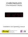
1
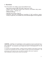
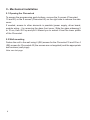
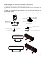
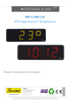
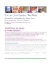
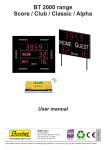
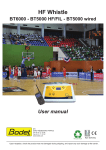
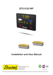
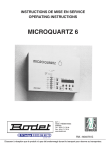
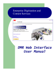
CHRONOLED
Timer/Stopwatch Display
Installation and operating manual
BP1
49340 TRÉMENTINES FRANCE
Tel. 02 41 71 72 00
Fax 02 41 71 72 02
www.bodet-sport.com
Ref. 606985F
Upon receipt, always check the product for damage during shipment. If any is found, you may file a damage claim with the carrier.
1
Table of contents
I - Overview..................................................................................3
II - Mechanical installation............................................................4
II.1 Opening the Chronoled......................................................................... 4
II.2 Wall mounting........................................................................................ 4
II.3 Mounting on car roof rack holder (Chronoled 15 and 25 only).............. 5
II.4 Mounting on tripod stand (Chronoled 15 and 25 only).......................... 6
III - Electrical installation...............................................................7
III.1 Power supply........................................................................................ 7
III.2 Connecting a double-sided Chronoled................................................. 7
III.3 Configuring the dips............................................................................. 7
III.4 Chronoleds in series............................................................................. 8
III.5 Pairing an HF remote control............................................................... 8
IV - Paramater Setting..................................................................9
IV.1 Main menu........................................................................................... 10
IV.2 CHRO menu: timer/stopwatch settings............................................... 11
IV.3 SCORE menu: score entry.................................................................. 13
IV.4 TIME menu: time setting..................................................................... 13
IV.5 PROG menu: luminosity, relays and time base adjusments............... 15
IV.6 TECH menu: ....................................................................................... 16
IV.7 TEST menu: panel test and version display........................................ 19
V - Types of time synchronisation................................................19
VI - Technical features.................................................................20
2
I - Overview
The Chronoled is an outdoor count up/countdown timer.
- Very high luminosity SMD LED with 6 digits and 3 dots.
- Display: time of day with second, timer (count up, countdown, day), score.
- Supply voltage: 110/230 v AC.
- Aluminum housing.
- Available Led colours: Red (R).
-Automatic luminosity management according to light conditions (sunny,
cloudy or night time). On 2 sided units, each side manages its own brightness.
CAUTION : installation and maintenance of this equipment must be performed by a
authorized person. This is a dual voltage product that can be powered power by 110v
AC or 240v AC. The installation must comply with the IEC 364 standard (NFC 15-100
for France).
A 16 Amps circuit breaker (phase + neutral) must be installed in the power source line
to protect the equipment and must be tripped off when performing maintenance. The
equipment must be powered up only after the installation has been completed.
Any modification on the product cancels the warranty.
3
II - Mechanical installation
II.1 Opening the ChronoLed
To access the programming push-buttons, remove the 2 screws (Chronoled
15 and 25) or the 4 screws (Chronoled 45) on the right side to remove the side
cover.
If needed, access to other elements is possible (power supply, driver board,
module wiring...) by removing the glass front cover. Slide the glass sideways 5
to 10 cm, then lift it up and pull it toward you to extract it from the lower profile
of the Chronoled.
II.2 Wall mounting
Fasten the unit to the wall using 4 (Ø6) screws for the Chronoled 15 and 25 or 4
(Ø8) screws for Chronoled 45 (the screws are not supplied) and the appropriate
wall anchors (wall plugs).
Note: see last page.
4
II.3 Mounting on car roof rack (Chronoled 15 and 25 only)
1/ Assemble the roof rack brackets as shown in B and D.
2/ Fasten the Chronoled (or both Chronoleds if double side) on the brackets as
in A.
3/ Install the Chonoled-brackets assembly on the roof rack bars using the the
hand-screws as in C
Caution : when the Chronoled is mounted on the roof, drive the vehicle slowly (60 km/h
maximum).
A
A
Nut HU M6 Zn
Screw H M6x16
Flat washer Ø6 Zi
Max section of roof bars :
Width : 59 mm
Thickness : 43 mm
C
B
Nut HU M6 Zn
D
Flat washer Ø6 Zi
Screw TH M6x16
Tooth lock washer Ø6 Zn
355,00
C
B
Tooth lockwasher Ø6 Zn
Star button for screw M6
Screw TH M6x16
Nut HU M6 Zn
SCREW H M6x60 Zi
Chronoled gallery holder flange S/A
Mounting with Chronoled 15
Gallery bracket
565,00
Mounting with Chronoled 25
800,00
5
II.4 Mounting on tripod stand (Chronoled 15 and 25 only)
1/ Fasten the Chronoled bracket onto the base plate of the stand with the 4
screws as in B.
2/ Fasten the Chronoled (or both Chronoleds if double side) on the bracket with
4 screws as in A.
A
Flat washer Ø8 Zn
B
Screw H M8 X 20 ZI
Screw H M6 X 20 ZI
HU nut M6 Zn
Flat washer Ø8 Zn
Nut HU M8 Z
Flat washer Ø6 Zi
Flat washer Ø6 Zi
A
C
Double Sided mount
Stand bracket
C
B
Stand baseplate
Mounting stand
6
III - Electrical installation
III.1 Power supply
The power supply is a dual voltage unit. The
selection of the input voltage is done by mean
of a slide switch located on the side of the
power supply. By default the selected input voltage is 230v 50/60Hz. To set it
for 115v, first remove the digit card in front of the power supply and then the Z
shape bracket to have access to the switch.
Connect the Chronoled power cord to 115/230v AC mains or the 12v DC power
inverter (cigarette lighter) if it is used.
Note 1: remove the glass to gain access to the power supply unit (see § II. 1).
Note 2: the adhesive protection delivered must be stuck above the terminal strips of the
power supply at the end of the wiring, preventing direct contact with hazardous voltages.
III.2 Connecting a double-sided Chronoled
In the case of a double-sided Chronoled, one panel must be master and the
other one salve. A synchronization cable kit made of two sections must be used.
The male section connects to the RS485 connector of the master and the female
section to the slave. Connect the 2 sections together.
III.3 Configuring the dips
The dips are set at the factory, however if several Chronoleds are to be connected
together then dips 3 to 5 need to be set according to following table (next page).
7
Clock type
Dip 1
Dip 2
CHRONOLED
1
0
RS 485 connector for slave sync.
Clock type
MASTER
SLAVE
Dip 1
Dip 2
Dip 3
Dip 4
Dip 5
HMT LED
0
0
/
/
/
HMS LED
0
1
/
/
/
Slave 1
1
0
0
0
1
Slave 2
1
0
0
1
0
Slave 3
1
0
0
1
1
Slave 4
1
0
1
0
0
Slave 5
1
0
1
0
1
Slave 6
1
0
1
1
0
Slave 7
1
0
1
1
1
III.4 Chronoleds in series
Up to 8 Chronoleds can be connected in series (1 master and up to 7 slaves).
- Set one Chronoled as master via the dips, then all the other Chronoled as
slave (each slave Chronoled must have a unique number). See table above.
- Connect the RS485 synchronization cable to the RS485 connector of each
Chronoled. See the above illustration.
III.5 Pairing an HF remote control
Using the HF remote control to operate the Chronoled requires pairing. This operation is
performed in the factory.
Pairing is accomplished during a limited time of 30sec after powering up the
Chonoled by holding down the [T] key for 1 sec, 88 is then displayed.
Unpairing a remote control is performed identically to pairing.
Note: everytime a Chronoled is powered up, a remote control which is already
paired is inactive for 30 seconds.
8
IV - Parameter Setting
To set the parameters of the Chronoled, use the 2 push-buttons located inside
the Chronoled or the HF remote control. The push-buttons are accessible by
removing the right side of the Chronoled.
Caution: to prevent short circuits, do not insert any metallic objects in the Chronoled.
S : ‘S’ key
+ : ‘R’ key
Sel
+
M : menu key
T : version / Test key
Programming push-buttons
HF remote control
[Sel] push button (inside Chronoled only)
- To call the main menu (chro/time/scor/prog/test) hold down this push-button
for 1 second.
- To exit a menu, hold down this push-button for 1 second.
- Press briefly on this push-button to validate the menu or the parameter
previously selected.
[+] push button (inside Chronoled only)
- While displaying a menu, press this button to select the next menu or
parameter.
[S] Remote control key
- While displaying a menu, press this key briefly to validate the menu or the
parameter previously selected.
– In timing mode, press this key to start the timer, and press this key again
stop the timer.
[R] Remote control key
- Selects the next menu or next parameter.
- In timing mode, resets the timer when it is stopped.
[M] Remote control key
- Hold down this key (1 sec) to call the main menu (chrono / time / scor / prog
/ test).
- Press this key briefly to exit a programming menu.
9
[T] Remote control key (called test key)
- Hold down this key for 1 sec. to perform a display test and to display the
software version number.
Note on remote control and Chronoled keys
- During the process of data entry, if no key is pressed for 30 sec, automatic
menu exit is performed, without validating the currently selected parameter.
A parameter is validated only after pressing [S].
IV.1 Main menu
The main menu provides access to all setting functions of the Chronoled display.
It contains 5 menus :
CHRO :sets timing functions (count up/count down).
TIME : sets time of day and date.
SCOR :manages 2 scores, Home and Visitors, from 0 to 99.
PROG :sets brightness of the display LEDs, sets a countup/countdown
loop, sets the time of the relay at end of timing.
TECH : Allows the selection of the display mode12/24h and the display
order month/day (31.12 or 12.31), to set the time synchronisation
mode, to set the options of time zone and summer/winter changeover, to modify the time base, to select the temperature unit (C or
F), temperature display mode, to apply an offset to the temperature and the humidity and to set the channel of the HF transmitter.
This menu is for technician only.
TEST : tests the display panel to check that each LED runs properly and
displays the software version number.
Just validate one of these first 3 menus (CHRO, SCOR
and TIME) to display the corresponding mode.
For example, to display the time when the Chronoled displays
a time countdown, just enter the TIME menu and validate.
1. The display is idle while displaying the time. Press [M] on
the remote control (or the [Sel] key for 1 sec) to call the main
menu.
2. The first menu displayed is the CHRO menu, to go to the
next menu (tIME), press the [R] key.
3.
10
Press [S] to validate the chosen menu. Conversely, pressing
[M] lets you exit the menu (or the [Sel] key for 3 sec).
IV.2 CHRO menu: count and countdown setting
1. Enter the CHRO menu (see page 10).
2. A message flashes (up, down or day). Choose the count
mode with the [R] key. «Up» starts timing, «down» starts
countdown timing, «dayd» starts a day countdown and
«dayU» starts a day count up (the counting will stop on the
last day at midnight).
3. Press the [S] key to validate your choice.
4. Enter hours with the [R] key. Press the [S] key to validate.
Then enter minutes with the [R] key. Press the [S] key to
validate. And finally, enter the seconds with the [R] key.
Press the [S] key to validate.
Note : the value entered is the max value to reach in counting
mode and the starting value in the countdown mode.
5. If Day chosen:
a.Choice between J (jour in French), d (day in English) and
(tage in German) using the [R] key. Press the [S] key to validate
the choice.
b.Enter the unit of days to count down with the [R] key. Press
the [S] key to validate.
c.Enter the tens of days to count down with the [R] key. Press
the [S] key to validate.
d.Enter the hundreds of days to count down with the [R] key.
Press the [S] key to validate.
Note that on the last day the countdown changes to Hours / minutes / seconds countdown.
11
6. In the «dayd» programming select the time (hour/minute) at
which the countdown should stop (programming «00H00»
the countdown will stop at midnight on the last day).
The hour digits blink(0 to 23h). Edit with the [R] key.
Press [S] to validate the hours and move on to set the
minutes
The minutes digits blinks (0 to 59). Edit with the [R] key.
Press [S] to validate
Nota: On the last day the countdown changes to Hours/
Minutes. On the last hour the countdown Changes to Minutes/
Seconds countdown.
7. The display returns to the normal mode with the timer mode
being selected (see ‘[Sel] push button (inside Chronoled
only)’, page 9 for the operation of the timer).
12
V.3 SCORE menu: entering scores
1. Enter the SCORE menu (see page 10).
2. The S or + key (top left) increments home scores by one
point.
3. The M or – key (bottom left) decrements home scores by
one point.
4. The R or + key (top right) increments visitor score by one
point. A long press resets all scores.
5. The T or – key (bottom right) decrements the visitors score
by one point.
IV.4 TIME menu: setting the time of day
1. Enter the TIME menu (see page 10).
2. Time flashes (0 to 23h). Modify using the [R] key.
3. Press the [S] key to validate time and go to minutes setting.
4. Minutes flash (0 to 59). Modify with the [R] key.
5. Press the [S] key to validate the minutes.
6.
The year blinks. Mofify with the [R] key.
7.
Press [S] to validate the year.
13
8. The day flashes. Modify with [R].
9. Press [S] to validate the day.
10. The month flashes.Modify with [R].
11. APress [S] to validate the month.
12. The display goes back to the normal mode after the time
and date setting has been validated.
14
IV.5 PROG menu: setting brightness, relay, time base
1. Enter the PROG menu (see page 10).
2. The brightness value flashes (A1 to A3 then M1 to 9).
Modify with the [R] key. The values A1 to A3 are automatic
brightness adjustments (brightness varies according to
ambient light). The values M1 to M9 are manual brightness
settings (brightness is fixed regardless of ambient light).
Brightness of the display is modified in real time, and in
a multi-panel installation, each panel manages its own
brightness..
3. Press the [S] key to validate brightness to set the time base.
4. The selected timing mode (*) flashes (ru or St). Modify with
the [R] key.
The ‘ru’ mode (run) allows to restart automatically and
permanently the same count/countdown (at the end of a count/
countdown, the Chronoled returns automatically to its initial
value and restarts the same count/countdown).
The ‘St’ mode (stop) stops at the end of count/countdown.
5. Press the [S] key to validate the parameter and go to setting
the time of the count/countdown end relay (*).
6. The time of activation of the automatic relay (horn) at the
end of count/countdown (*) flashes (from 0 to 9 or – to
deactivate the relay). Modify with the [R] key.
7. Press the [S] key to validate.
9. Press the [S] key to validate the timing mode. The display
returns to the normal mode.
(*) These menus exist only when the timing mode is activated.
15
IV.6 Menu TECH :
1. Enter TECH menu: press «SEL» or «S» or «M» for 1 sec.
Select the menu by pressing [+]. Validate with [S] and
proceed to the selection of the synchronisation mode.
2.
The synchronisation mode flashes (Independent «Ind»,
Radio «rAd», GPS «GPS» see chapter V - Types of time
synchronisation - for additional information of the time
synchronisation types). Select with[R].
3.
Display of the dynamic reception.
4.
Choose a pre-recorderd time zone and summer/winter
change-overs or choose the programmable mode (prog)
with the [R] key.
Programmable mode «GMt»: only the time shift can be
entered. The winter/summer change-over programming is not
possible.
a.If GMT was selected, press [S] to validate.
b.The hours of the time difference flash (from -11h +11h).
Modify with [R].
c.Validate the hours with[S].
d.The minutes of the time difference flash (00 or 30).
Modify with [R].
e.Validate the time difference with [S].
Programmable «PrG» mode: mode to enter the summer/winter
and winter/summer change-over dates.along with the time
difference.
a.If «PrG» was selected, press [S] to validate.
b.The winter/summer change-over month flashes. Modify
with [R].
c.Validate the month with [S].
d.The 3rd digit corresponding to the day within the month of
the change-over flashes.
16
On a non Fixed date:
- Modify the le 3RD digit corresponding to the week number
within the month (1 to 5) with [R]. Validate with [S].
- Modify the 4th digit corresponding to the number of the
day within the week (1 to 7: 1 Monday and 7 Sunday)
with [R]. Validate with [S].
On a Fixed date:
- Choose F on the 3rd digit with [R]. Validate with [S].
- Select the number of the day within the month (1 to 31)
with [R]. Validate with [S].
e.The summer/winter month number flashes . Modify with
[R].
f. Validate the month with [S].
g.The 3rd digit, corresponding to the day within the monthof
the summer/winter change-over flashes.
On a non Fixed date:
- Modify the le 3RD digit corresponding to the week number
within the month (1 to 5) with [R]. Validate with [S].
- Modify the 4th digit corresponding to the number of the
day within the week (1 to 7: 1 Monday and 7 Sunday)
with [R]. Validate with [S].
On a Fixed date:
- Choose F on the 3rd digit with [R]. Validate with [S].
- Select the number of the day within the month (1 to 31)
with [R]. Validate with [S].
h. The hours of the time difference flash (from -11h +11h).
Modify with [R]. Validate the hours with[S].
j. The minutes of the time difference flash (00 or 30).
Modify with [R]. Validate the time difference with [S].
17
Central Europe zone “Eur” (France, Germany, etc.) (GMT +01
hour).
Winter > Summer = last Sunday of March at 2h00.
Summer > Winter = last Sunday of October at 3h00.
Wertern Europe zone “Eu_1” (England, Portugal, Irlande)
(GMT +00 hour).
Winter > Summer = last Sunday of March at 1h00.
Summer > Winter = last Sunday of October at 2h00.
Eastern Europe zone “EASt” (Greece, Finlande, etc.) (GMT
+02 hours).
Winter > Summer = last Sunday of March at 3h00.
Summer > Winter = last Sunday of October at h00.
Eastern USA “USAE” (New York, Toronto, etc) (GMT -05
hours).
Winter > Summer = second Sunday of March at 2h00.
Summer > Winter = first Sunday of November at 2h00.
Central USA “USAC” (Chicago) (GMT -06 hours).
Winter > Summer = second Sunday of March at 2h00.
Summer > Winter = first Sunday of November at 2h00.
Montain USA “USAM” (Denver) (GMT -07 hours).
Winter > Summer = second Sunday of March at 2h00.
Summer > Winter = first Sunday of November at 2h00.
Pacific USA “USAP” (Los Angeles) (GMT -08 hours).
Winter > Summer = second Sunday of March at 2h00.
Summer > Winter = first Sunday of November at 2h00.
Australia “AUS” (Sydney) (GMT +10 hours).
Winter > Summer = first Sunday of October at 2h00.
Summer > Winter = first Sunday of April at 3h00.
5.Press [S] to validate. The display goes back to normal
mode.
18
IV.7 TEST menu: test and version display
1. Enter the TEST menu (see page 10 and page 9).
2. All LEDs must be lit.
3. Press the [S] or [T] key to go to the next test.
4. All LEDs must be off.
5. Press the [S] or [T] key to go to the next test.
6. Display the addressing number of each module (the 3-point
module stays off). The number normally corresponds to the
example in the right-hand diagram. For HMS, the display is
1 2 3 4 5 6.
7. The Chronoled software version number is displayed.
8. Press the [S] or [T] key to return to the normal mode.
V - Types of time synchronisation
Independent Mode «Ind»
•The clock is entirely independent, the time information comes from its own time base. .
FI or DCF Radio Synchronised Mode «rAd»
•The clock is independent, the time information comes from its own time base which is compared
with the signal sent by the FI or DCF transmitter and is corrected in case of a drift.
•The radio synchronisation allows displaying the time with absolute precisioin.
GPS Mode «GPS»
•The clock is independent, the time information comes from its own time base which is compared
with the signal received from the GPS system and is corrected in case of a drift.
•The radio synchronisation allows displaying the time with absolute precisioin..
19
V - Technical specifications
Designation
Specifications
Power supply
115V / 230V -10/+6% 50/60HZ
Installation diagram
Diagram TT, TN or IT
Electric isolation
Class I
Main power supply
3 (phase, neutral and earth) terminals for 0.75mm² to 2.5mm² wires
Time base precision
≤ 0.2 sec/day
Remote control frequency and coverage distance
433 MHz/ Maximum 100 metre in open space
Cable input by sealed grommets
Mains supply cable: M23 – sheath Ø 10 to 14 mm
Dimensions
Repeater or mains: M20 – sheath Ø 7 to 10 mm
Settings saved in case of mains power off
Permanent
Operating temperature
-20°C to +50°C
Protection rating
IP 54 / IK 07
CHRONOLED 45
567
620
2000
122
2400
CHRONOLED 25
1500
73
121
317
385
90,5
800
CHRONOLED 15
1100
242
310
90,5
20
565