1
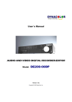
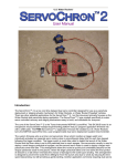
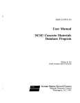
Wireless M-Bus Application for PAN7550
User Manual
February 15, 2010
Chapter 1
Summary
M-Bus is widely accepted in many regions of the world as a basis for new advanced metering infrastructure (AMI)
installations. Its wireless implementation leads to competitive products that are easy to install and to maintain. The
Wireless M-Bus standard (EN 13757-4:2005) specifies the wireless communication between meters for water, gas,
heat and electricity, and the data concentrators. The stzedn stack implements the protocols for Wireless M-Bus. It
has proven interoperability with the modules of well-known manufacturers on the different protocol layers and is
compliant with the current Wireless M-Bus standard [4]. It is optimized towards a compromize of small footprint
and excellent modularity and scalability.
This document describes a demonstration software based on the stzedn protocol stack for Wireless M-Bus.
Wireless M-BusDocumentation
Contents
1 Summary
2
2 Application setup
4
3 Demo application
7
3.1 Introduction . . . . . . . . . . . . . . . . . . . . . . . . . . . . . . . . . . . . . . . . . . . . . . . . . . . . . . . .
7
3.2 Serial interface . . . . . . . . . . . . . . . . . . . . . . . . . . . . . . . . . . . . . . . . . . . . . . . . . . . . . . .
8
3.3 Meter Device . . . . . . . . . . . . . . . . . . . . . . . . . . . . . . . . . . . . . . . . . . . . . . . . . . . . . . . .
9
3.3.1 Introcuction . . . . . . . . . . . . . . . . . . . . . . . . . . . . . . . . . . . . . . . . . . . . . . . . . . . .
9
3.3.2 Buttons . . . . . . . . . . . . . . . . . . . . . . . . . . . . . . . . . . . . . . . . . . . . . . . . . . . . . . . 10
3.3.3 LEDs . . . . . . . . . . . . . . . . . . . . . . . . . . . . . . . . . . . . . . . . . . . . . . . . . . . . . . . . 10
3.3.4 Serial interface . . . . . . . . . . . . . . . . . . . . . . . . . . . . . . . . . . . . . . . . . . . . . . . . . . 10
3.4 Data Collector . . . . . . . . . . . . . . . . . . . . . . . . . . . . . . . . . . . . . . . . . . . . . . . . . . . . . . . 11
3.4.1 Introduction . . . . . . . . . . . . . . . . . . . . . . . . . . . . . . . . . . . . . . . . . . . . . . . . . . . . 11
3.4.2 Buttons . . . . . . . . . . . . . . . . . . . . . . . . . . . . . . . . . . . . . . . . . . . . . . . . . . . . . . . 11
3.4.3 LEDs . . . . . . . . . . . . . . . . . . . . . . . . . . . . . . . . . . . . . . . . . . . . . . . . . . . . . . . . 11
3.4.4 Serial interface . . . . . . . . . . . . . . . . . . . . . . . . . . . . . . . . . . . . . . . . . . . . . . . . . . 12
3.5 Network Sniffer . . . . . . . . . . . . . . . . . . . . . . . . . . . . . . . . . . . . . . . . . . . . . . . . . . . . . . 13
3.5.1 Introduction . . . . . . . . . . . . . . . . . . . . . . . . . . . . . . . . . . . . . . . . . . . . . . . . . . . . 13
3.5.2 Buttons . . . . . . . . . . . . . . . . . . . . . . . . . . . . . . . . . . . . . . . . . . . . . . . . . . . . . . . 13
3.5.3 LEDs . . . . . . . . . . . . . . . . . . . . . . . . . . . . . . . . . . . . . . . . . . . . . . . . . . . . . . . . 13
3.5.4 Serial interface . . . . . . . . . . . . . . . . . . . . . . . . . . . . . . . . . . . . . . . . . . . . . . . . . . 13
4 Tools and further options
15
4.1 Introduction . . . . . . . . . . . . . . . . . . . . . . . . . . . . . . . . . . . . . . . . . . . . . . . . . . . . . . . . 15
4.2 capt2web Wireless M-Bus Monitoring and Commissioning Tool . . . . . . . . . . . . . . . . . . . . . . . . . 15
4.3 Wireless M-Bus Protocol Stack . . . . . . . . . . . . . . . . . . . . . . . . . . . . . . . . . . . . . . . . . . . . . 17
5 Available Software Configurations and Documentation
18
6 Related documents and contact information
20
Wireless M-BusDocumentation
Chapter 2
Application setup
To run the application described in chapter 3, the following steps are to perform. The numbers in angle brackets
(<1>) in the list below refer to the red numbers in Figure 2.1. For details concerning the Testboard ver. 1.1, please
refer to [12].
Figure 2.1: PAN7550 Testboard ver. 1.1 connectors
1. Make sure that pins 1 and 2 of header <1> (JP1) are shortened.
2. Connect the Testboard ver. 1.1 to your PC using a standard USB A-B cable.
3. Being asked for a driver, please download and install the FTDI driver for your operating system [9].
4. If the hardware works and the device is installed correctly, LED5 <5> is illuminated. Otherwise, try to plug
the USB cable again or check the fuse F1.
5. Connect header <2> of your evaluation board to your debug adapter. A list of appropriate adapters can be
found at [10]
6. Open the FET-Pro430 (FET MSP430 Flash Programmer) [11].
7. Select "File" - "Load Setup".
Open the file "prog_config_pan7550.cfg".
8. Select "Setup" - "Connection/Device Reset".
Wireless M-BusDocumentation
CHAPTER 2. APPLICATION SETUP
page 5
Figure 2.2: Target’s Connection/Reset Options
Choose the debug adapter the PAN7550 is connected to.
Make sure that JTAG is selected and leave the window clicking on "OK".
9. Select "Setup" - "Memory Options".
Figure 2.3: Memory Options
Make sure that the settings are as shown in Figure 2.3. "Used by Code File" would also work.
Close the window clicking on "OK".
10. Click on "Open Code File" and choose the flash file msp430pan7550_s2 (t2)_collector.hex for the data collector
OR msp430pan7550_s2 (t2)_meter.hex for the meter device OR msp430pan7550_sniffer.hex for the network
sniffer.
Selecting "Texas Instruments (*.txt)" file type makes sure that the right files are loaded.
Wireless M-BusDocumentation
CHAPTER 2. APPLICATION SETUP
page 6
11. Make sure that the correct microcontroller group (MSP430F2xx) and device (MSP430F2274) are selected as
shown in Figure 2.4.
Figure 2.4: ERASE FLASH and WRITE FLASH
12. Click on "ERASE FLASH" and check the step to pass.
13. Click on "WRITE FLASH" and make sure that this works as well.
14. Disconnect the debug adapter and restart the device pressing the "Reset" button <4> of the Testboard ver. 1.1.
15. Repeat the steps described for the second device, but make sure to select the second code file.
16. Now, your boards are ready to run the application.
Wireless M-BusDocumentation
Chapter 3
Demo application
3.1
Introduction
This implementation shows the protocol packets transmitted in a bidirectional communication setup of a data collector and a single meter device. Unidirectional communication is also available for the modules used, but it should
only apply for devices providing extremely restricted memory ressources. Bidirectional communication is by far more
flexible, and it may even save energy, depending on the device settings. As the memory of the PAN7550 is sufficient
for a metering application plus a bidirectional communication, this option is presented in the demonstration setup.
Figure 3.1: Demo with a meter device and a data collector
In communication mode S2, the meter device sends periodical user data. The interval is determined to 30 seconds
(cf. Figure 3.2). After 1 minute, the connected data collector sends a status request. After receiving a response,
the presence of a user data class 1 is checked. If so, a user data class 1 request is sent. Finally, the bidirectional
communcation channel is closed by a "reset remote link" telegram.
In mode T2, the same procedure is used; but the meter device sends periodical access demand request telegrams
instead of user data. Every minute, the data collector waits for such an access demand request and sends a response.
Afterwards, the same requests as described for mode S2 are sent from data collector to meter device.
Figure 3.2 shows the telegram flows for mode S2 and mode T2.
Wireless M-BusDocumentation
CHAPTER 3. DEMO APPLICATION
page 8
Figure 3.2: Bidirectional communication of the demo application
3.2
Serial interface
To get used to the modules, a small serial interface application was added to the pure Wireless M-Bus communication software. This permits the transmission of small text in spontaneous user telegrams. On the Wireless M-Bus
application layer, they are encapsulated in manufacturer specific records for not to interfere with existing meters in
range. To establish the terminal connection, use the settings below:
• Select the virtual serial port of your USB connection (cf. chapter 2)
• Baud rate 115200 bps
• 8 data bits, 1 stop bit
• No parity bits
• No flow control
Wireless M-BusDocumentation
CHAPTER 3. DEMO APPLICATION
page 9
To check the correct serial setting, push Button 4. If the connection works correctly, the status message shown in the
upper part of Figure 3.3 appear in the terminal window.
When transmitting data, they are automatically split into chunks of 20 bytes. This derives from a limitation of the
serial buffer, whereas the communication stack would be able to transmit the data lengths specified by [4] of more
than 200 bytes. End each line with "line feed" (ASCII 0x0A) as shown for the example "Hello world" message.
Figure 3.3: Terminal window (here for meters)
3.3
3.3.1
Meter Device
Introcuction
If the meter device is in mode S2, it sends periodical user data telegrams.
In this demonstration, the packets contain a simple counter that is incremented for each user data telegram from 10
to 200. At the value of 200, the counter restarts.
Each telegram also includes the minimum and the maximum value. The minimum value is always 10. After starting
the meter device, the maximum value is identical to the minimum value, but it is updated with each user data
telegram.
If the device is started, the flag "user data class 1" available is set. A request for user data class 1 is therefore
answered with a user data telegram with no header and value 0xF1 (manufacturer specific). This informs the data
collector that the meter device was down or has encountered a reset.
Wireless M-BusDocumentation
CHAPTER 3. DEMO APPLICATION
3.3.2
page 10
Buttons
For the presented application, the buttons of Testboard ver. 1.1 have the following functions:
• Button 1: Installation
This button is always used for sending installation request telegrams. If no respond is received there are
sent maximal two repetitions. If an acknowledgement is received the meter device stops sending installation
request telegrams.
• Button 2: Error
This option is to simulate the transmission of error protocols according to [3]. A flag is set, which marks the
availability of user data class 1 information. If the user data class 1 is requested, the value 0xF2 (manufacturer
specific) is transmitted.
• Button 3: Spontaneous user data telegram
This buttons is used for sending spontaneous user data telegrams. The telegram includes a counter value
which is incremented each button push and counts up to 255. After this it restarts at 0.
• Button 4: Target information
Pushing this button causes the module to display the current settings of the PAN7550 in the terminal window.
3.3.3
LEDs
• LED 1: This LED is lit during the installation procedure.
• LED 2: This LED is switched on when button 2 (cf. chapter 3.3.2) is pressed and is switched off if the error is
read.
• LED 3: This LED flashes when a telegram is sent.
• LED 4: This LED flashes when a telegram is received.
3.3.4
Serial interface
The meter device supports a serial connection as described in chapter 3.2. Any message can be transmitted, which
can also be used to cause extended communication traffic. If the radio connection to the data collector cannot be
established, use the information provided after pressing Button 4 to check that the configuration is identical (both
S2 or T2), and that the roles are different.
Wireless M-BusDocumentation
CHAPTER 3. DEMO APPLICATION
3.4
page 11
Data Collector
3.4.1
Introduction
In mode S2, the data collector is by default in receive mode to wait for user data telegrams from the connected
meter device.
Every minute it sends a status request to check if user data class 1 are available. Upon a positive reply, user data
class 1 are requested and directly afterwards, a user data class 2 request is sent.
In mode T2, the data collector behaves nearly identical, but before exchanging user data, access demand requests
are transmitted.
3.4.2
Buttons
For the buttons, the following functions are available:
• Button 1: Installation
After pressing this button, the data collector enters installation mode. It waits for incoming installation requests for 10 seconds. If such a request is received, the data collector sends an installation response.
Installation requests are ignored as long as the data collector is not in installation mode.
• Button 2: User data class 2 request
If this button is pushed a bidirectional communication is opened for each connected meter device. After this
user data class 2 is requested from each meter.
Be careful: If mode T2 is chosen the data collector waits for incoming access demand requests before sending
its own request telegrams.
• Button 4: Target information
Pushing this button causes the module to display the current settings of the PAN7550 in the terminal window.
The other buttons are not used in the current configuration.
3.4.3
LEDs
• LED 1: This LED is lit during the installation procedure.
• LED 3: This LED flashes when a telegram is sent.
• LED 4: This LED flashes when a telegram is received.
Wireless M-BusDocumentation
CHAPTER 3. DEMO APPLICATION
3.4.4
page 12
Serial interface
The data collector supports a serial connection as described in chapter 3.2. If the connection to the meter device
cannot be established, use the information provided to check that the configuration is identical (both S2 or T2), and
that the roles are different. Figure 3.4 shows a screenshot of received data.
Figure 3.4: List of received data telegrams (mode T2)
• The first column includes the meter address.
• The second column show thetelegram type:
– IR for installation requests,
– UD for user datagrams, or
– ERR for error messages.
• The further columns includes the transmitted data
– user data counter, minimum and maximum values
– error messages
– text messages
Wireless M-BusDocumentation
CHAPTER 3. DEMO APPLICATION
3.5
page 13
Network Sniffer
3.5.1
Introduction
The network sniffer is used to collect and display all m-bus telegrams which are received. Because of the different
RF settings in S and T modes it is not possible to read the telegrams of both modes at the same time.
To collecto the transmissions of T2 devices, two sniffers are used, on in S mode and the other one in T mode.
The running time of the sniffer application is limited to 30 minutes. After this reading incoming telegrams is stopped
and all LEDs are switched on.
3.5.2
Buttons
For the buttons, the following functions are available:
• Button 1: Mode switching
After pressing this button, the receiving mode is changed. The sniffer provides mode S1 and T1.
• Button 4: Target information
Pushing this button causes the module to display the current settings of the PAN7550 in the terminal window.
The other buttons are not used in the current configuration.
3.5.3
LEDs
• LED 1: This LED is lit during the initialisation procedure.
• LED 2: This LED toggles when a telegram is received.
3.5.4
Serial interface
The sniffer supports a serial connection as described in chapter 3.2.
Figure 3.5 shows a screenshot of received data.
Wireless M-BusDocumentation
CHAPTER 3. DEMO APPLICATION
page 14
Figure 3.5: List of received data telegrams (mode T1)
• The first column shows the RSSI level (Received Signal Strength Indication).
• All following columns include the fields of the telegram and are shown as HEX-values.
– CRC: Each Wireless M-Bustelegram is segmented into several blocks. Each block includes a CRC value. If
the checksums of all blocks are valid "OK" is displayed.
– L: The length field includes the number of bytes transmitted in the telegram.
– C: Telegram type. To get further information read [8, 5.1.2].
– M: This field includes the id of the manufacturer. Read [3, 5.5] to get further information.
– A: This number identifies the meter device. The address of the device is the combincation of M, A, V and
T fields.
– V: The version of the meter is defined by the manufacturer.
– T: This field shows the type of the meter device. In [3, Table 3] the type values are specivfied.
– CI: This field describes the application data in DATA. All allowed values are listed in [3, Table 1].
Wireless M-BusDocumentation
Chapter 4
Tools and further options
4.1
Introduction
The protocol stack can be used in different versions. Refer to chapter 4.3 for details. Especially for large networks of
some thousand meter devices and data collectors, additional tools are useful to efficiently setup and run the network.
One of them is described below.
4.2
capt2web Wireless M-Bus Monitoring and Commissioning Tool
Wireless communication benefits from commissioning tools during system setup. Once the network is running,
errors or intrusion attempts can be logged.
The network monitors known to the authors require software installation on the monitoring machine. In case of
non-standard protocols, additional hardware drivers are necessary to connect the sniffing module. The solution
from stzedn follows a different approach. The sniffing device runs an embedded web server, to which any web
browser can connect. By default, the connection uses Ethernet, but GPRS, modem, and Wi-Fi are available. Figure
4.1 shows the hardware device for capturing data.
Figure 4.1: Hardware for in-field Wireless M-Bus data monitoring
The web server inside of the sniffing device implements web 2.0 services to periodically refresh the client browser
while only transmitting the M-Bus telegrams received. Java scripts are used for telegram filtering, colouring, and
evaluation. Figure 4.2 shows an example browser window including the packet timeline. The packets shown were
logged during a session of the demonstration program. Logging to USB USB Flash Drives and later download eases
Wireless M-BusDocumentation
CHAPTER 4. TOOLS AND FURTHER OPTIONS
long-term tests. In case of questions or a quotation for the tool, please contact [email protected].
Figure 4.2: capt2web Network Monitoring Tool
.
Wireless M-BusDocumentation
page 16
CHAPTER 4. TOOLS AND FURTHER OPTIONS
4.3
page 17
Wireless M-Bus Protocol Stack
The demonstration application shows only little of the opportunities of the complete stack implementation. For the
implementation of stzedn’s Wireless M-Bus implementation, additional versions are available. First, the module can
be used like a modem that serially connects to the custom application. An AT command set is used to setup and run
the Wireless M-Bus network. In this case, programming the module is not necessary as the device is preconfigured.
An extended command set is also available to minimize the communication overhead. In all of these configurations,
the module is exclusively used for the communication task.
But for applications that are sensitive concerning the energy consumption or cost, often only one microcontroller is
to usae for both, the communication and the sensor application. in these cases, the protocol stack can be purchased
as library or as source code in different versions. Please contact [email protected] for a quotation. Refer to Table
5.1 for a list of available versions.
Wireless M-BusDocumentation
Chapter 5
Available Software Configurations and
Documentation
The stzedn stack for Wireless M-Buscomprehends the full protocol implementation.
The software may be delivered in various configurations shown in table 5.1. The software always comes with a documentation containing the interface description of the protocol layers’ library, or with the complete documentation
when buying the software in source code.
The software configurations shown in table 5.1 are currently supported:
Wireless M-BusDocumentation
CHAPTER 5. AVAILABLE SOFTWARE CONFIGURATIONS AND DOCUMENTATION
Software
Documentation
page 19
Purpose
• Example application (binary
file)
• Configuration software (PC)
• Demo application
• Configuration software
• Commissioning tests, simple traffic generator
• AT parser application (binary file)
• Configuration software (PC)
• AT command parser
• Configuration software
• Wireless M-Busmodem application based on the application layer or the data link
layer
• Application layer, data link
layer, and physical layer (library)
• Example user application
(source code)
• Configuration software (PC)
• Application layer - API description
• User application (documented source code in
C)
• Configuration software
• Implementation of a standard Wireless M-Busdata
collector and metering device
• Data link layer and physical
layer (library)
• Application layer (source
code)
• Example user application
(source code)
• Configuration software (PC)
• Data link layer and physical
layer - API description
• Application layer - API description
• User application (documented source code in
C)
• Configuration software
• Wireless M-Busdata collector and metering device
with custom application
layer to be used e.g. together with an existing
application layer for wired
M-Bus
• Complete protocol stack
(source code, ANSI C)
• Example user application
(source code)
• Configuration software (PC)
• Fully documented source
code
• All API descriptions (additional document)
• Configuration software
• Source code portable to
other µC platforms and custom hardware, optimization
for the application
Table 5.1: Available Software Configurations
Library customization may also be available upon request.
Wireless M-BusDocumentation
Chapter 6
Related documents and contact
information
[1] “Communication systems for meters and remote reading of meters.” Part 1: Data exchange; English version
EN 13757-1, 2002.
[2] “Communication systems for meters and remote reading of meters.” Part 2: Physical and link layer; English
version EN 137572, 2004.
[3] “Communication systems for meters and remote reading of meters.” Part 3: Dedicated application layer; English version EN 137573, 2004.
[4] “Communication systems for meters and remote reading of meters.” Part 4: Wireless meter readout (Radio
meter reading for operation in the 868 MHz to 870 MHz SRD band); German version EN 137574, 2005.
[5] “Communication systems for meters and remote reading of meters.” Part 5: Relaying; English version prEN
13757-5, 2007.
[6] “Communication systems for meters and remote reading of meters.” CEN TC 294.
[7] “Home and building electronic systems (hbes).” CENELEC TC 205.
[8] “Telecontrol equipment and systems.” Part 5: Transmission protocols; EN 870-5, 2002.
[9] “ftdi virtual com port drivers.” http://www.ftdichip.com/Drivers/VCP.htm, 2009.
[10] “list of msp430 jtag adapters.” http://www.ti.com/msp430, 2009.
[11] “elprotronic msp430 flashing tool.” http://www.elprotronic.com/fetpro430.html, 2009.
[12] “Testboard ver. 1.1 user manual.” http://www.ecom.panasonic.de/pdf/engl/164ext2.pdf, 2009.
[13] “Wireless m-bus stack and demo applications.” http://www.stzedn.de/wireless-m-bus.html, 2010.
[14] “Testboard ver. 1.1 user manual.” http://focus.ti.com/docs/toolsw/folders/print/ez430-chronos.html, 2010.
[15] “Java runtime environment.” http://java.sun.com, 2010.
Wireless M-BusDocumentation
Document History
Version
date
Changes
source
0.1
0.2
0.3
2009-12-08
2009-12-11
2009-12-16
tg
dl
tg
0.4
0.5
2010-02-05
2010-02-11
Initial Release
Adaption for the PAN7550 Testboard v1.1
Meter device: Sending spontaneous user data telegrams
added.
Data collector: Sending user data class 2 requests added.
Sniffer application added
Adaption for the eZ430-Chronos Development Tool
Table 6.1: Document History
Contact Information
In case of questions or ideas for improvement, please contact
Steinbeis Transfer Center
Embedded Design and Networking
c/o Duale Hochschule Loerrach
Hangstrasse 46-50
D-79539 Loerrach
Germany
Tel: +49 7634-6949-340
Fax: +49 7634-5049-886
url: http://www.stzedn.de
e-mail: [email protected]
Wireless M-BusDocumentation
tg
tg