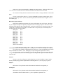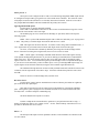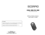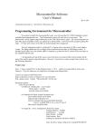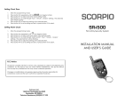
1
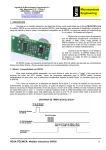
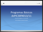
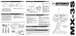
Microcontroller board rev 3
User’s Manual
Rev. 1/1/09
Send comments/corrections to: Alex Brown [email protected]
Introduction:
The Microcontroller board is designed for the Leaf series of robots (members.cox.net/rbirac).
These robots use a laptop computer or other PC equivalent to perform high level control processing. The
microcontroller board provides input/output capability as well as drive motor control and other functions
(see function list following). The microcontroller communicates with the laptop via messages on a USB
bus. The associated processor is a Motorola HC9S12DP256 which operates at 25 Mhz and has 256K of
flash memory and 4K of RAM. It is programmed in C.
The included software is capable of being adapted to many robot configurations. This is
accomplished with .ini configuration files on the laptop which are downloaded to the microcontroller.
These configuration files provide for calibration of drive motor encoders, setting gains for driving the
motors, setting up the software to process the selected sensor/effector configuration, etc.
Functional support:
Drives up to 3 motors using sign/magnitude PWM control. These signals are used to drive
external H-bridges which may be of varying types to meet the motor requirements.
Reads up to 3 quadrature encoders.
Can read up to 8 external analog sensors (often IR range sensors)
Can drive up to 7 RC servos.
Up to seven of the above RC servos may be replaced by sonar range sensors.
(sum of sonars and RC servos = 7)
has 12 bits of discrete I/O ports.
Has one I2C bus (software supports reading a CMPS03 compass)
Has one SPI bus (not implemented in software)
Has two RS232 serial ports (2nd port not implemented in software)
Reads battery voltage
Reads outputs of a dual axis (x/y) accelerometer
Reads a yaw axis rate gyro and integrates the data in software to implement a directional gyro.
Software does low level navigation tracking of X/Y coordinates.
Software includes test software for verifying microcontroller board construction.
USB Interface:
The microcontroller board sends all sensed and computed data to the laptop over USB messages
that are transmitted at 16 hz.
The microcontroller board receives messages from the laptop specifying configuration parameters,
motor drive commands, and navigation data.
These messages are specified in the microcontroller software documentation.
Specific drivers from ftdichip.com must be installed in the laptop to read the microcontroller USB.
Analog inputs (labeled IR0 – IR7)
These ports can each read a signal varying over the range of 0 to 5 vdc. Be sure that the applied
signals do not go out of this range or you risk damaging your processor. Analog signals are read by the
microcontroller at 61 hz from a 10 bit ATD converter. They are sent to the laptop at 15 hz. Right now,
only the most recent value is sent to the laptop. In the future, configuration data may be specified for
these inputs to send: the most recent value, the average or midrange of the previous 4 values, filtered
values or whatever.
These analog signals may be defined as any appropriate sensor in the laptop computer. Right now,
they are all defined as Sharp IR range finders (GP2D12). Necessary conversions and calibrations are
performed in the laptop.
See the Sensor Hookup data later in this document for details on wiring the SRF04s to the modular
plugs.
Battery voltage is handled internally the same as an analog signal. It will require calibration to be
performed in the laptop after the raw ATD signal is received.
RCservo/Sonar inputs (labeled RC0 – RC6)
Each of these ports is configurable as either an RC servo driver or as a Sonar sensor. These ports
may be used for either SRF04 or Polaroid type sonars. (applicable to all revisions of boards)
Hardware changes are required to change a board from RC servo operation to sonar. The RC
servos are designed to be powered from a 6 vdc source which is available on a bus strip running near each
RC port. Sonars are designed to be powered by an 8 vdc bus also running nearby.
Rev 0 to 2 board instructions:
The "standard" board design (as in the assembly directions) configures RC 0-3 as sonar and RC 46 as RC servos. That is, RC 4-6 have a jumper installed to provide 6 vdc and RC 0-3 as prewired to 8 vdc
in the circuit board traces.
RC 4-6 can be changed from RC servo to sonar just by changing the jumper from 6 to 8 vdc as
needed. RC 0-3 are changed by cutting the trace between the 8 vdc bus and the module jack power pin and
adding a jumper from the power pin to the 6 vdc bus. Subsequently, they can be changed back to sonar by
changing the jumper from 6 to 8 vdc.
Rev 3 board instructions:
Each RC port will be seen to have a row of 3 circular soldering pads located just above
the silkscreen name of the port. Solder a three pin IDC header strip into each of these. There is no longer a
“default” configuration built into the board as described for earlier revisions above. You must apply an
IDC jumper for each RC port to attach it to +8 or +6 vdc as you desire. For + 8 vdc (sonars), place the
jumper between the two pins closest to the associated modular phone jack. To select for an RC servo, place
the jumper between the two pins farthest from the jack.
Note: Sonars must start with RC0 and work upwards. RC servo ports are all those above the
sonars.
The software is configured by setting the "numsonars" parameter in the laptop Microconfig.ini
file. e.g. if numsonars = 3, then RC0-2 will be processed as sonars and RC 3-6 as RC servos. The
microcontroller software message returns the raw time of flight reading in microseconds to the laptop. The
laptop is responsible for converting this value to distance and providing whatever calibrations are desired.
Sonars are set up to run autonomously as SRF04 sonar range detectors. Each sonar will be read
every 4th cycle (ie. About 15 hz), hence all sonar range data will be transferred to the laptop.
See the Sensor Hookup data later in this document for details on wiring the SRF04s to the modular
plugs.
If a port is specified as an RC servo, it can be commanded by messages from the laptop. These
messages are still being defined. See the Sensor Hookup document for details about wiring RC servos to
the modular plugs.
Discrete I/O ports (DIO 0-2)
Each of these modular ports supplies 8 vdc power and ground as well as 4 I/O pins. These pins
may be configured as inputs or outputs by configuration files in the laptop computer. Data can be set on
output pins by the laptop by the command message, and can be read at any time on the data message. The
12 DIO pins are configured, set and read by 16 bit data words. The specific pins on each DIO port are
arranged in the above words as follows:
DIO 0 pin 2
bit 0
DIO 0 pin 3
bit 1
DIO 0 pin 4
bit 2
DIO 0 pin 5
bit 3
DIO 1 pin 2
bit 4
DIO 1 pin 3
bit 5
DIO 1 pin 4
bit 6
DIO 1 pin 5
bit 7
DIO 2 pin 2
bit 8
DIO 2 pin 3
bit 9
DIO 2 pin 4
bit 10
DIO 2 pin 5
bit 11
(bits 12-15 are unused)
e.g. to set all DIO 0 pins and pins 2 and 3 of DIO 1 as outputs and the remaining pins as inputs,
set DIOcfg to 0x003F in the MicroConfig.ini file. (setting a bit to "1" makes it an output, "0"s are inputs)
To set pins 0 and 1 of DIO 0 to high and all other outputs low, send a command message from the
laptop with DIOcmd = 0x0003. (note: attempting to set pins configured as inputs has no effect.)
To read input pins, process the DIOdata word in the data message from the microcontroller. Bits
configured as inputs will read the value at the input pin, bits configured as outputs will read the last data
sent to that pin.
I2C port
This port is currently configured to read heading from a Devantech CMPS03 compass module.
I'm not particularly happy with the implementation method right now. So, I'm not going to go into it.
SPI port
This interface is a 4 pin header on the microcontroller board and is not supported yet.
Serial port 1
This interface is a 4 pin header on the microcontroller board and is not supported yet.
(list hardware electrical characteristics: e.g. drive capabilities, impedances etc.)
Motor ports 0 – 2
These ports can be configured to drive either a conventional sign-magnitude PWM output OR can
be configured to output an RC type signal for use with external motor controllers. This selection is done
with jumpers located on the main board. See assembly instructions for details. Software exists to drive
only outputs MOT0 and MOT1 which are intended for the primary drive motors.
Sign-magnitude PWM option:
For this option, no jumpers should be installed.
Ports 0 and 1 are intended to control the two drive motors of a differential steering robot. Port 0
drives the left wheel and Port 1 drives the right.
The modular plugs are to be connected to an H-bridge (or equivalent) which will accept the
following signals:
PWM: This is a pulse width modulated signal with a 15 Khz rate and a duty cycle varying from 0
to 100%. The polarity is such that "high" means motor ON and "low" is OFF.
DIR: This signal sets the motor direction. It assumes a mirror image motor installation hence, a
"low" signal means to go forward on the Left motor and "high" means forward on the right.
Of course, motor direction is ultimately defined by the wiring between the H-bridge and the
motor. If the motor is turning the wrong direction, these two wires can be reversed.
BRK: A brake signal is an H-bridge command which shorts the motor leads together causing
some dynamic braking during deceleration. It provides no braking at a standstill, hence cannot hold the
robot in one place. The microcontroller software does not use this feature and sets both brake output
signals to the "low" state. You can hook this signal up to the H-bridge if it has a compatible brake input;
or you can leave it unconnected if you have no brake input; or wire your h-bridge BRK input to high, if it
requires high to release the brake function (leaving the microcontroller signal disconnected).
The LM18201 H-bridge has been used successfully with this board and is suitable for motors with
continuous current requirements of less than 3 amps. A board is available from picobotics.com as their
Pico-HB.
Please let me know of other h-bridges that you make work.
RC motor driver:
For this option, jumpers must be installed between the two leftmost pins and the two rightmost
pins of the motor drive option pins.
This mode of operation provides an output signal on the PWM wire of the MOT0 and MOT1
jacks. This signal is a pulse varying between 1.0 millisecond (full reverse) and 2.0 milliseconds (full
forward) with a 1.5 millisecond pulse commanding stop.
The brake and direction outputs are not used.
In order to adapt the microcontroller drive equations to your particular motor drive setup, a
number of parameters must be set in a laptop .ini file. See the "Motor Hookup" instructions for a test
procedure to determine the correct values.
ENC 0 – 2
The board provides inputs for three quadrature encoders. ENC0 and ENC1 are allocated to the
two drive wheels.
The modular plugs provide +5 vdc power and a ground as well as two encoder signal inputs which
are referred to as channels A and B. The encoder signals must be proper quadrature data varying from 0 to
+5 vdc (roughly) and be 90 degrees out of phase.
The allocation of channels A and B to the respective outputs of the encoder depends on your
particular installation. In the "Motor Hookup" instructions, the proper wiring will be determined.
The encoder should have high resolution to provide good performance. In particular, the
encoders should give a resolution on each channel of at least 1 click per millimeter of wheel motion with 20
to 40 clicks/mm being desirable.
Accelerometer
An Analog devices ADXL202 dual axis accelerometer is installed. This accelerometer is capable
of reading +/- 2 g's in each axis. Microcontroller software reads the outputs of the accelerometer and
transmits the results to the laptop computer for calibration and use.
The accelerometer is oriented to measure acceleration in the forward direction and to the side.
For accurate readings, it is important that the microcontroller board be mounted in the robot horizontally
with the top of the board pointed straight forward (that is, the side of the board with the I2C port is pointed
forward. It is equally important that the accelerometer board be mounted horizontally on the
microcontroller board. Holes are provided in the microcontroller board where standoff can be installed, if
necessary, to keep the accelerometer board in position.
Yaw Rate Gyro
An Analog devices ADXR150 yaw rate gyro is installed. This rate gyro measures the rate of
change in direction. It does not measure direction itself as a true gyro does. It has a range of +/- 150
degrees/second.
The software performs an integration of the rate signal and generates a relatively accurate heading
signal. An integrated rate signal will always have drift over time caused by inaccuracy in the rate gyro null.
This particular implementation will usually have a drift rate of less than 3 degrees/minute while the robot is
standing still. Performance may vary if the robot is doing a lot of turning.
The laptop software can compare the generated heading to the compass signal and make
corrections when it chooses.
This heading signal plus odometry is used to generate X/Y coordinates to indicate the robot's position. This
computation is done in the microcontroller for best accuracy. However, the laptop can use this data for
higher level navigation tasks and can correct the X/Y computations when it chooses.
Sensor connections:
In general, sensors are connected to a modular jack which supplies +8 vdc and ground as well as
the interfacing signals. Hence, each 5 vdc sensor must have its own 5 volt regulator. This technique has
proven to be effective at minimizing noise in the system.
Digikey part number H9003 is a suitable modular jack to use as shown below. Or, you may
choose to wire directly to the modular phone cable, skipping the jack. Actually, the jack is nice since when
you install the sensor on the robot it is easy to make a new cord of just the right length.
Sharp GP2D12 IR range sensor
The GP2D12 generates large voltage transients on the power supply input. This implementation
dedicates a voltage regulator to each GPD12 with associated capacitors hence keeping most of the noise
local.
The amount of remaining noise reflected back into the modular jack is proportional to the size of
the input capacitor (10 uf). The noise is under 100 mv peak-to-peak on both the ground and +8 vdc bus
using 10 uf.
SRF04 Sonar
Motor / Encoder connections
The H bridge wiring is for the PicoHB available from picobotics.com. The encoder wiring is
shown as an example using a Pittman encoder. Change as necessary for your own setup.
RC servo
The wires of various RC servo manufacturers use different wire color codes and connector plug style. It is
often a challenge to figure them out.
Some examples follow:
Manufacturer
power
Ground
Signal
Airtronics/Sanwa old
Red, outside pin
Black, middle pin
White, inside pin
Airtronics/Sanwa Z
Red, middle pin
Black, outside pin
Blue, inside pin
Futaba J
Red, middle pin
Black, outside pin
White, inside pin
Hitec
Red, middle pin
Black, outside pin
Yellow, inside pin
KO Propo
Red, outside pin
Black, middle pin Blue or White, inside pin
Kyosho/Pulsar
Red
Black
Yellow
Japan Radio(JR)
Red, middle pin
Brown, outside pin
Orange, inside pin
for more info, see: http://wolfstone.halloweenhost.com/TechBase/svoint_RCServos.html