1
Functional support:
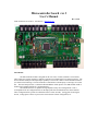
Drives up to 3 motors using sign/magnitude PWM control. These signals are used to drive
external H-bridges which may be of varying types to meet the motor requirements.
Reads up to 3 quadrature encoders.
Can read up to 8 external analog sensors (often IR range sensors)
Can drive up to 7 RC servos.
Up to seven of the above RC servos may be replaced by sonar range sensors.
(sum of sonars and RC servos = 7)
has 12 bits of discrete I/O ports.
Has one I2C bus (software supports reading a CMPS03 compass)
Has one SPI bus (not implemented in software)
Has two RS232 serial ports (2nd port not implemented in software)
Reads battery voltage
Reads outputs of a dual axis (x/y) accelerometer
Reads a yaw axis rate gyro and integrates the data in software to implement a directional gyro.
Software does low level navigation tracking of X/Y coordinates.
Software includes test software for verifying microcontroller board construction.
USB Interface:
The microcontroller board sends all sensed and computed data to the laptop over USB messages
that are transmitted at 16 hz.
The microcontroller board receives messages from the laptop specifying configuration parameters,
motor drive commands, and navigation data.
These messages are specified in the microcontroller software documentation.
Specific drivers from ftdichip.com must be installed in the laptop to read the microcontroller USB.
Analog inputs (labeled IR0 – IR7)
These ports can each read a signal varying over the range of 0 to 5 vdc. Be sure that the applied
signals do not go out of this range or you risk damaging your processor. Analog signals are read by the
microcontroller at 61 hz from a 10 bit ATD converter. They are sent to the laptop at 15 hz. Right now,
only the most recent value is sent to the laptop. In the future, configuration data may be specified for
these inputs to send: the most recent value, the average or midrange of the previous 4 values, filtered
values or whatever.
These analog signals may be defined as any appropriate sensor in the laptop computer. Right now,
they are all defined as Sharp IR range finders (GP2D12). Necessary conversions and calibrations are
performed in the laptop.
See the Sensor Hookup data later in this document for details on wiring the SRF04s to the modular
plugs.
Battery voltage is handled internally the same as an analog signal. It will require calibration to be
performed in the laptop after the raw ATD signal is received.