1
RCservo/Sonar inputs (labeled RC0 – RC6)
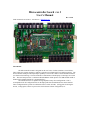
Each of these ports is configurable as either an RC servo driver or as a Sonar sensor. These ports
may be used for either SRF04 or Polaroid type sonars. (applicable to all revisions of boards)
Hardware changes are required to change a board from RC servo operation to sonar. The RC
servos are designed to be powered from a 6 vdc source which is available on a bus strip running near each
RC port. Sonars are designed to be powered by an 8 vdc bus also running nearby.
Rev 0 to 2 board instructions:
The "standard" board design (as in the assembly directions) configures RC 0-3 as sonar and RC 46 as RC servos. That is, RC 4-6 have a jumper installed to provide 6 vdc and RC 0-3 as prewired to 8 vdc
in the circuit board traces.
RC 4-6 can be changed from RC servo to sonar just by changing the jumper from 6 to 8 vdc as
needed. RC 0-3 are changed by cutting the trace between the 8 vdc bus and the module jack power pin and
adding a jumper from the power pin to the 6 vdc bus. Subsequently, they can be changed back to sonar by
changing the jumper from 6 to 8 vdc.
Rev 3 board instructions:
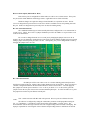
Each RC port will be seen to have a row of 3 circular soldering pads located just above
the silkscreen name of the port. Solder a three pin IDC header strip into each of these. There is no longer a
“default” configuration built into the board as described for earlier revisions above. You must apply an
IDC jumper for each RC port to attach it to +8 or +6 vdc as you desire. For + 8 vdc (sonars), place the
jumper between the two pins closest to the associated modular phone jack. To select for an RC servo, place
the jumper between the two pins farthest from the jack.
Note: Sonars must start with RC0 and work upwards. RC servo ports are all those above the
sonars.
The software is configured by setting the "numsonars" parameter in the laptop Microconfig.ini
file. e.g. if numsonars = 3, then RC0-2 will be processed as sonars and RC 3-6 as RC servos. The
microcontroller software message returns the raw time of flight reading in microseconds to the laptop. The
laptop is responsible for converting this value to distance and providing whatever calibrations are desired.