1
Motor ports 0 – 2
These ports can be configured to drive either a conventional sign-magnitude PWM output OR can
be configured to output an RC type signal for use with external motor controllers. This selection is done
with jumpers located on the main board. See assembly instructions for details. Software exists to drive
only outputs MOT0 and MOT1 which are intended for the primary drive motors.
Sign-magnitude PWM option:
For this option, no jumpers should be installed.
Ports 0 and 1 are intended to control the two drive motors of a differential steering robot. Port 0
drives the left wheel and Port 1 drives the right.
The modular plugs are to be connected to an H-bridge (or equivalent) which will accept the
following signals:
PWM: This is a pulse width modulated signal with a 15 Khz rate and a duty cycle varying from 0
to 100%. The polarity is such that "high" means motor ON and "low" is OFF.
DIR: This signal sets the motor direction. It assumes a mirror image motor installation hence, a
"low" signal means to go forward on the Left motor and "high" means forward on the right.
Of course, motor direction is ultimately defined by the wiring between the H-bridge and the
motor. If the motor is turning the wrong direction, these two wires can be reversed.
BRK: A brake signal is an H-bridge command which shorts the motor leads together causing
some dynamic braking during deceleration. It provides no braking at a standstill, hence cannot hold the
robot in one place. The microcontroller software does not use this feature and sets both brake output
signals to the "low" state. You can hook this signal up to the H-bridge if it has a compatible brake input;
or you can leave it unconnected if you have no brake input; or wire your h-bridge BRK input to high, if it
requires high to release the brake function (leaving the microcontroller signal disconnected).
The LM18201 H-bridge has been used successfully with this board and is suitable for motors with
continuous current requirements of less than 3 amps. A board is available from picobotics.com as their
Pico-HB.
Please let me know of other h-bridges that you make work.
RC motor driver:
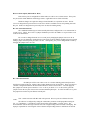
For this option, jumpers must be installed between the two leftmost pins and the two rightmost
pins of the motor drive option pins.
This mode of operation provides an output signal on the PWM wire of the MOT0 and MOT1
jacks. This signal is a pulse varying between 1.0 millisecond (full reverse) and 2.0 milliseconds (full
forward) with a 1.5 millisecond pulse commanding stop.
The brake and direction outputs are not used.
In order to adapt the microcontroller drive equations to your particular motor drive setup, a
number of parameters must be set in a laptop .ini file. See the "Motor Hookup" instructions for a test
procedure to determine the correct values.
ENC 0 – 2
The board provides inputs for three quadrature encoders. ENC0 and ENC1 are allocated to the
two drive wheels.