1
To our customers,
Old Company Name in Catalogs and Other Documents
On April 1st, 2010, NEC Electronics Corporation merged with Renesas Technology
Corporation, and Renesas Electronics Corporation took over all the business of both
companies. Therefore, although the old company name remains in this document, it is a valid
Renesas Electronics document. We appreciate your understanding.
Renesas Electronics website: http://www.renesas.com
April 1st, 2010
Renesas Electronics Corporation
Issued by: Renesas Electronics Corporation (http://www.renesas.com)
Send any inquiries to http://www.renesas.com/inquiry.
Notice
1.
2.
3.
4.
5.
6.
7.
All information included in this document is current as of the date this document is issued. Such information, however, is
subject to change without any prior notice. Before purchasing or using any Renesas Electronics products listed herein, please
confirm the latest product information with a Renesas Electronics sales office. Also, please pay regular and careful attention to
additional and different information to be disclosed by Renesas Electronics such as that disclosed through our website.
Renesas Electronics does not assume any liability for infringement of patents, copyrights, or other intellectual property rights
of third parties by or arising from the use of Renesas Electronics products or technical information described in this document.
No license, express, implied or otherwise, is granted hereby under any patents, copyrights or other intellectual property rights
of Renesas Electronics or others.
You should not alter, modify, copy, or otherwise misappropriate any Renesas Electronics product, whether in whole or in part.
Descriptions of circuits, software and other related information in this document are provided only to illustrate the operation of
semiconductor products and application examples. You are fully responsible for the incorporation of these circuits, software,
and information in the design of your equipment. Renesas Electronics assumes no responsibility for any losses incurred by
you or third parties arising from the use of these circuits, software, or information.
When exporting the products or technology described in this document, you should comply with the applicable export control
laws and regulations and follow the procedures required by such laws and regulations. You should not use Renesas
Electronics products or the technology described in this document for any purpose relating to military applications or use by
the military, including but not limited to the development of weapons of mass destruction. Renesas Electronics products and
technology may not be used for or incorporated into any products or systems whose manufacture, use, or sale is prohibited
under any applicable domestic or foreign laws or regulations.
Renesas Electronics has used reasonable care in preparing the information included in this document, but Renesas Electronics
does not warrant that such information is error free. Renesas Electronics assumes no liability whatsoever for any damages
incurred by you resulting from errors in or omissions from the information included herein.
Renesas Electronics products are classified according to the following three quality grades: “Standard”, “High Quality”, and
“Specific”. The recommended applications for each Renesas Electronics product depends on the product’s quality grade, as
indicated below. You must check the quality grade of each Renesas Electronics product before using it in a particular
application. You may not use any Renesas Electronics product for any application categorized as “Specific” without the prior
written consent of Renesas Electronics. Further, you may not use any Renesas Electronics product for any application for
which it is not intended without the prior written consent of Renesas Electronics. Renesas Electronics shall not be in any way
liable for any damages or losses incurred by you or third parties arising from the use of any Renesas Electronics product for an
application categorized as “Specific” or for which the product is not intended where you have failed to obtain the prior written
consent of Renesas Electronics. The quality grade of each Renesas Electronics product is “Standard” unless otherwise
expressly specified in a Renesas Electronics data sheets or data books, etc.
“Standard”:
8.
9.
10.
11.
12.
Computers; office equipment; communications equipment; test and measurement equipment; audio and visual
equipment; home electronic appliances; machine tools; personal electronic equipment; and industrial robots.
“High Quality”: Transportation equipment (automobiles, trains, ships, etc.); traffic control systems; anti-disaster systems; anticrime systems; safety equipment; and medical equipment not specifically designed for life support.
“Specific”:
Aircraft; aerospace equipment; submersible repeaters; nuclear reactor control systems; medical equipment or
systems for life support (e.g. artificial life support devices or systems), surgical implantations, or healthcare
intervention (e.g. excision, etc.), and any other applications or purposes that pose a direct threat to human life.
You should use the Renesas Electronics products described in this document within the range specified by Renesas Electronics,
especially with respect to the maximum rating, operating supply voltage range, movement power voltage range, heat radiation
characteristics, installation and other product characteristics. Renesas Electronics shall have no liability for malfunctions or
damages arising out of the use of Renesas Electronics products beyond such specified ranges.
Although Renesas Electronics endeavors to improve the quality and reliability of its products, semiconductor products have
specific characteristics such as the occurrence of failure at a certain rate and malfunctions under certain use conditions. Further,
Renesas Electronics products are not subject to radiation resistance design. Please be sure to implement safety measures to
guard them against the possibility of physical injury, and injury or damage caused by fire in the event of the failure of a
Renesas Electronics product, such as safety design for hardware and software including but not limited to redundancy, fire
control and malfunction prevention, appropriate treatment for aging degradation or any other appropriate measures. Because
the evaluation of microcomputer software alone is very difficult, please evaluate the safety of the final products or system
manufactured by you.
Please contact a Renesas Electronics sales office for details as to environmental matters such as the environmental
compatibility of each Renesas Electronics product. Please use Renesas Electronics products in compliance with all applicable
laws and regulations that regulate the inclusion or use of controlled substances, including without limitation, the EU RoHS
Directive. Renesas Electronics assumes no liability for damages or losses occurring as a result of your noncompliance with
applicable laws and regulations.
This document may not be reproduced or duplicated, in any form, in whole or in part, without prior written consent of Renesas
Electronics.
Please contact a Renesas Electronics sales office if you have any questions regarding the information contained in this
document or Renesas Electronics products, or if you have any other inquiries.
(Note 1) “Renesas Electronics” as used in this document means Renesas Electronics Corporation and also includes its majorityowned subsidiaries.
(Note 2) “Renesas Electronics product(s)” means any product developed or manufactured by or for Renesas Electronics.
To all our customers
Regarding the change of names mentioned in the document, such as Hitachi
Electric and Hitachi XX, to Renesas Technology Corp.
The semiconductor operations of Mitsubishi Electric and Hitachi were transferred to Renesas
Technology Corporation on April 1st 2003. These operations include microcomputer, logic, analog
and discrete devices, and memory chips other than DRAMs (flash memory, SRAMs etc.)
Accordingly, although Hitachi, Hitachi, Ltd., Hitachi Semiconductors, and other Hitachi brand
names are mentioned in the document, these names have in fact all been changed to Renesas
Technology Corp. Thank you for your understanding. Except for our corporate trademark, logo and
corporate statement, no changes whatsoever have been made to the contents of the document, and
these changes do not constitute any alteration to the contents of the document itself.
Renesas Technology Home Page: http://www.renesas.com
Renesas Technology Corp.
Customer Support Dept.
April 1, 2003
User’s Manual
SH7410 E8000 Emulator
HS7410EDD82H
User’s Manual
Renesas Microcomputer
Development Environment
System
Rev.1.0 2000.09
Cautions
1. Hitachi neither warrants nor grants licenses of any rights of Hitachi’s or any third party’s
patent, copyright, trademark, or other intellectual property rights for information contained in
this document. Hitachi bears no responsibility for problems that may arise with third party’s
rights, including intellectual property rights, in connection with use of the information
contained in this document.
2. Products and product specifications may be subject to change without notice. Confirm that you
have received the latest product standards or specifications before final design, purchase or
use.
3. Hitachi makes every attempt to ensure that its products are of high quality and reliability.
However, contact Hitachi’s sales office before using the product in an application that
demands especially high quality and reliability or where its failure or malfunction may directly
threaten human life or cause risk of bodily injury, such as aerospace, aeronautics, nuclear
power, combustion control, transportation, traffic, safety equipment or medical equipment for
life support.
4. Design your application so that the product is used within the ranges guaranteed by Hitachi
particularly for maximum rating, operating supply voltage range, heat radiation characteristics,
installation conditions and other characteristics. Hitachi bears no responsibility for failure or
damage when used beyond the guaranteed ranges. Even within the guaranteed ranges,
consider normally foreseeable failure rates or failure modes in semiconductor devices and
employ systemic measures such as fail-safes, so that the equipment incorporating Hitachi
product does not cause bodily injury, fire or other consequential damage due to operation of
the Hitachi product.
5. This product is not designed to be radiation resistant.
6. No one is permitted to reproduce or duplicate, in any form, the whole or part of this document
without written approval from Hitachi.
7. Contact Hitachi’s sales office for any questions regarding this document or Hitachi
semiconductor products.
Preface
Thank you for purchasing the emulator for the Hitachi microcomputer SH7410.
CAUTION
Read section 3, Preparation before Use in Part I, E8000 Guide
of this user’s Manual before using the emulator product. Incorrect
operation will damage the user system, the emulator product, and
the user program.
The emulator is an efficient software and hardware development tool for systems based on Hitachi
microcomputer SH7410. By exchanging the device control board and the EV-chip board, this
emulator can also be used for other microcomputers.
This manual describes the emulator functions and operations. Please read this manual carefully in
order to gain a full understanding of the emulator’s performance. In particular, be sure to read
section 1.2, Warnings, in Part I, E8000 Guide.
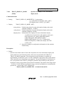
A 3.5-inch system floppy disk in PC 1.44-MB format is packaged together with the EV-chip
board.
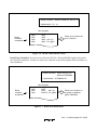
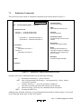
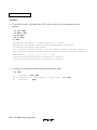
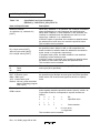
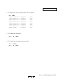
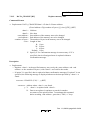
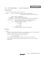
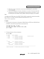
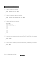
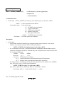
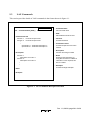
SH7410 E8000 SYSTEM
1. SYSTEM (HS7410EDD82SF)
Vm.nn
2. PC I/F (HS8000EIW01SF)
Vm.nn
3. DIAGNOSTIC TEST
Vm.nn
'xx.xx.xx
HITACHI
E8000
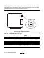
Figure E8000 System Disk
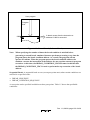
Before using the system disk, back up it to a floppy disk according to the instructions in the
manuals of the personal computer and the operating system.
Install (copy) the system disk to the personal computer connected to the emulator. For details on
the copy procedure, refer to section 3.7, System Program Installation in Part I, E8000 Guide.
Related Manuals:
SH7410EBK82H Manual
SH7410EBH82H Manual
Lan Board Manual
Description Notes on Using the PC Interface Board (HS6000EII01H)
SH Series C Compiler User’s Manual
SPARC* SH Series Cross Assembler User’s Manual
SPARC H Series Linkage Editor User’s Manual
SPARC H Series Librarian User’s Manual
Integration Manager User’s Manual
Description Notes of Integration Manager SH7410 Definition File
SH7410 E8000 Hitachi Debugging Interface User’s Manual
Note: SPARC is a registered trademark of SPARC Intemational, INC.
IMPORTANT INFORMATION
READ FIRST
• READ this user’s manual before using this emulator product.
• KEEP the user’s manual handy for future reference.
Do not attempt to use the emulator product until you fully understand its mechanism.
Emulator Product:
Throughout this document, the term “emulator product” shall be defined as the following
products produced only by Hitachi, Ltd. excluding all subsidiary products.
• Emulator station
• Device control board
• EV-chip board
The user system or a host computer is not included in this definition.
Purpose of the Emulator Product:
This emulator product is a software and hardware development tool for systems employing the
Hitachi microcomputer HD6437410 (hereafter referred to as SH7410). By exchanging the device
control board and EV-chip board, this emulator product can also be used for systems using other
E8000-series microcomputers. This emulator product must only be used for the above purpose.
Limited Applications:
This emulator product is not authorized for use in MEDICAL, atomic energy, aeronautical or
space technology applications without consent of the appropriate officer of a Hitachi sales
company. Such use includes, but is not limited to, use in life support systems. Buyers of this
emulator product must notify the relevant Hitachi sales offices before planning to use the product
in such applications.
Improvement Policy:
Hitachi, Ltd. (including its subsidiaries, hereafter collectively referred to as Hitachi) pursues a
policy of continuing improvement in design, performance, and safety of the emulator product.
Hitachi reserves the right to change, wholly or partially, the specifications, design, user’s manual,
and other documentation at any time without notice.
Target User of the Emulator Product:
This emulator product should only be used by those who have carefully read and thoroughly
understood the information and restrictions contained in the user’s manual. Do not attempt to use
the emulator product until you fully understand its mechanism.
It is highly recommended that first-time users be instructed by users that are well versed in the
operation of the emulator product.
LIMITED WARRANTY
Hitachi warrants its emulator products to be manufactured in
accordance with published specifications and free from defects in
material and/or workmanship. Hitachi, at its option, will repair or
replace any emulator products returned intact to the factory,
transportation charges prepaid, which Hitachi, upon inspection,
determine to be defective in material and/or workmanship.
The foregoing shall constitute the sole remedy for any breach of
Hitachi’s warranty. See the Hitachi warranty booklet for details on the
warranty period. This warranty extends only to you, the original
Purchaser. It is not transferable to anyone who subsequently purchases
the emulator product from you. Hitachi is not liable for any claim made
by a third party or made by you for a third party.
DISCLAIMER
HITACHI MAKES NO WARRANTIES, EITHER EXPRESS OR
IMPLIED, ORAL OR WRITTEN, EXCEPT AS PROVIDED
HEREIN, INCLUDING WITHOUT LIMITATION THEREOF,
WARRANTIES AS TO MARKETABILITY, MERCHANTABILITY,
FITNESS FOR ANY PARTICULAR PURPOSE OR USE, OR
AGAINST INFRINGEMENT OF ANY PATENT. IN NO EVENT
SHALL HITACHI BE LIABLE FOR ANY DIRECT, INCIDENTAL
OR CONSEQUENTIAL DAMAGES OF ANY NATURE, OR
LOSSES OR EXPENSES RESULTING FROM ANY DEFECTIVE
EMULATOR PRODUCT, THE USE OF ANY EMULATOR
PRODUCT, OR ITS DOCUMENTATION, EVEN IF ADVISED
OF THE POSSIBILITY OF SUCH DAMAGES. EXCEPT AS
EXPRESSLY STATED OTHERWISE IN THIS WARRANTY,
THIS EMULATOR PRODUCT IS SOLD “AS IS ”, AND YOU
MUST ASSUME ALL RISK FOR THE USE AND RESULTS
OBTAINED FROM THE EMULATOR PRODUCT.
State Law:
Some states do not allow the exclusion or limitation of implied warranties or liability for
incidental or consequential damages, so the above limitation or exclusion may not apply to you.
This warranty gives you specific legal rights, and you may have other rights which may vary from
state to state.
The Warranty is Void in the Following Cases:
Hitachi shall have no liability or legal responsibility for any problems caused by misuse, abuse,
misapplication, neglect, improper handling, installation, repair or modifications of the emulator
product without Hitachi’s prior written consent or any problems caused by the user system.
All Rights Reserved:
This user’s manual and emulator product are copyrighted and all rights are reserved by Hitachi.
No part of this user’s manual, all or part, may be reproduced or duplicated in any form, in hardcopy or machine-readable form, by any means available without Hitachi’s prior written consent.
Other Important Things to Keep in Mind:
1. Circuitry and other examples described herein are meant merely to indicate the characteristics
and performance of Hitachi’s semiconductor products. Hitachi assumes no responsibility for
any intellectual property claims or other problems that may result from applications based on
the examples described herein.
2. No license is granted by implication or otherwise under any patents or other rights of any third
party or Hitachi.
Figures:
Some figures in this user’s manual may show items different from your actual system.
Limited Anticipation of Danger:
Hitachi cannot anticipate every possible circumstance that might involve a potential hazard.
The warnings in this user’s manual and on the emulator product are therefore not all inclusive.
Therefore, you must use the emulator product safely at your own risk.
SAFETY PAGE
READ FIRST
• READ this user’s manual before using this emulator product.
• KEEP the user’s manual handy for future reference.
Do not attempt to use the emulator product until you fully understand its mechanism.
DEFINITION OF SIGNAL WORDS
DANGER indicates an imminently hazardous situation which, if not avoided,
will result in DEATH or SERIOUS INJURY to you or other people.
WARNING indicates a potentially hazardous situation which, if not avoided,
could result in DEATH or SERIOUS INJURY to you or other people.
CAUTION indicates a hazardous situation which, if not avoided, may result in minor or
moderate injury to you or other people, or may result in damage to the
machine or loss of the user program. It may also be used to alert against
unsafe usage.
NOTE emphasizes essential information.
WARNING
Observe the precautions listed below. Failure to do so will result
in a FIRE HAZARD and will damage the user system and the
emulator product or will result in PERSONAL INJURY.
The USER PROGRAM will be LOST.
1. Carefully handle the emulator product to prevent receiving an
electric shock because the emulator product has a DC power
supply. Do not repair or remodel the emulator product by
yourself for electric shock prevention and quality assurance.
2. Always switch OFF the emulator and user system before
connecting or disconnecting any CABLES or PARTS.
3. Always before connecting, make sure that pin 1 on both sides
are correctly aligned.
4. Supply power according to the power specifications and do not
apply an incorrect power voltage. Use only the provided AC
power cable. Use only the specified type of fuse.
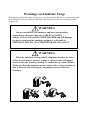
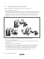
Warnings on Emulator Usage
Warnings described below apply as long as you use this emulator. Be sure to read and understand
the warnings below before using this emulator. Note that these are the main warnings, not the
complete list.
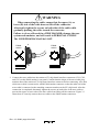
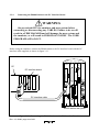
WARNING
Always switch OFF the emulator and user system before
connecting or disconnecting any CABLES or PARTS.
Failure to do so will result in a FIRE HAZARD and will damage
the user system and the emulator product or will result in
PERSONAL INJURY. The USER PROGRAM will be LOST.
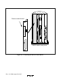
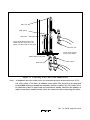
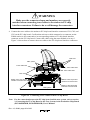
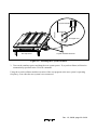
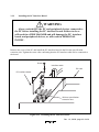
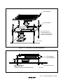
WARNING
Place the emulator station and EV-chip board so that the trace
cables are not bent or twisted. A bent or twisted cable will impose
stress on the user interface leading to connection or contact failure.
Make sure that the emulator station is placed in a secure position so
that it does not move during use nor impose stress on the user
interface.
HITACHI
E8000
POWER
RUN
HITA
CHI
E80
00
HITACHI
E8000
POWER
RUN
POWER
RUN
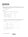
Contents
Part I E8000 Guide
Section 1 Overview............................................................................................3
1.1
1.2
1.3
1.4
Overview........................................................................................................................... 3
Warnings ........................................................................................................................... 6
Environmental Conditions ................................................................................................ 7
Components ...................................................................................................................... 8
1.4.1 E8000 Emulator Station....................................................................................... 8
1.4.2 SH7410 Device Control Board and EV-Chip Board ........................................... 8
1.4.3 Options................................................................................................................. 9
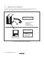
Section 2 Components .......................................................................................11
2.1
2.2
2.3
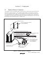
Emulator Hardware Components...................................................................................... 11
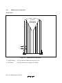
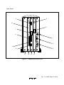
2.1.1 E8000 Station Components.................................................................................. 12
2.1.2 Device Control Board Components ..................................................................... 15
2.1.3 EV-Chip Board Components ............................................................................... 16
Emulator Software Components ....................................................................................... 18
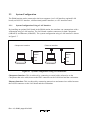
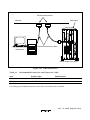
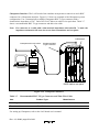
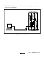
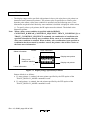
System Configuration ....................................................................................................... 20
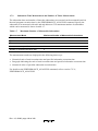
2.3.1 System Configuration Using a LAN Interface..................................................... 20
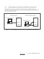
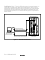
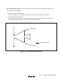
2.3.2 System Configuration Using an RS-232C or Bidirectional Parallel
Interface ............................................................................................................... 21
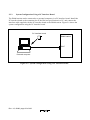
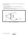
2.3.3 System Configuration Using a PC Interface Board ............................................. 22
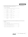
Section 3 Preparation before Use.......................................................................23
3.1
3.2
3.3
Emulator Preparation ........................................................................................................ 23
Emulator Connection ........................................................................................................ 25
3.2.1 Connecting the Device Control Board ................................................................. 25
3.2.2 Connecting the EV-Chip Board ........................................................................... 27
3.2.3 Connecting the External Probe ............................................................................ 31
3.2.4 Selecting the Clock .............................................................................................. 32
3.2.5 Connecting the System Ground ........................................................................... 35
System Connection ........................................................................................................... 37
3.3.1 PC Interface Board Specifications ....................................................................... 40
3.3.2 Switch Settings of the PC Interface Board........................................................... 41
3.3.3 Installing the PC Interface Board......................................................................... 43
3.3.4 Connecting the E8000 Station to the PC Interface Board.................................... 44
3.3.5 Connecting to a Personal Computer..................................................................... 45
3.3.6 Connecting to a LAN Interface............................................................................ 46
3.3.7 System Connection Examples.............................................................................. 48
Rev. 1.0, 09/00, page i of xi
3.4
3.5
3.6
3.7
3.8
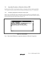
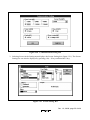
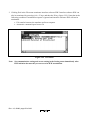
Operation Procedures of Interface Software IPW............................................................. 53
3.4.1 Installation and Initiation of Interface Software IPW .......................................... 53
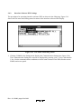
3.4.2 Interface Software IPW Settings.......................................................................... 54
3.4.3 Debugging Support Functions ............................................................................. 57
Power-On Procedures for Emulator .................................................................................. 59
3.5.1 Power-On Procedures for LAN Interface ............................................................ 59
3.5.2 Power-On Procedures for RS-232C Interface...................................................... 66
Emulator Monitor Commands .......................................................................................... 67
3.6.1 Emulator Monitor Initiation................................................................................. 67
3.6.2 S ........................................................................................................................... 68
3.6.3 F ........................................................................................................................... 69
3.6.4 L........................................................................................................................... 77
3.6.5 T........................................................................................................................... 78
System Program Installation ............................................................................................. 79
3.7.1 E8000 System Disk.............................................................................................. 79
3.7.2 Installation ........................................................................................................... 80
E8000 System Program Initiation ..................................................................................... 87
3.8.1 Initiation on Emulator Monitor............................................................................ 87
3.8.2 Automatic Initiation of E8000 System Program.................................................. 88
Section 4 Operating Examples ..........................................................................89
4.1
4.2
4.3
Emulator Operating Examples .......................................................................................... 89
Basic Examples ................................................................................................................. 90
4.2.1 Preparing for Connection of the LAN Host Computer ........................................ 90
4.2.2 Specifying the SH7410 Operating Mode ............................................................. 92
4.2.3 Allocating Standard Emulation Memory and Specifying Attributes ................... 93
4.2.4 Loading the User Program ................................................................................... 94
4.2.5 Executing the Program......................................................................................... 95
4.2.6 Setting a Software Breakpoint ............................................................................. 97
4.2.7 Executing a Single Step ....................................................................................... 98
4.2.8 Setting Hardware Break Conditions .................................................................... 99
4.2.9 Displaying Trace Information.............................................................................. 100
Application Examples ....................................................................................................... 102
4.3.1 Break with Pass Count Condition ........................................................................ 102
4.3.2 Conditional Trace ................................................................................................ 103
4.3.3 Parallel Mode....................................................................................................... 104
4.3.4 Searching Trace Information ............................................................................... 106
Part II Emulator Function Guide
Section 1 Emulator Functions............................................................................109
1.1
1.2
Overview........................................................................................................................... 109
Specification ..................................................................................................................... 110
Rev. 1.0, 09/00, page ii of xi
1.3
Realtime Emulation........................................................................................................... 118
1.3.1 Normal Mode....................................................................................................... 118
1.3.2 Cycle Reset Mode ................................................................................................ 119
1.3.3 Parallel Mode....................................................................................................... 121
1.4 Break Function.................................................................................................................. 124
1.4.1 Hardware Break ................................................................................................... 124
1.4.2 Software Break .................................................................................................... 132
1.4.3 Forced Break........................................................................................................ 136
1.5 Realtime Trace Function ................................................................................................... 137
1.5.1 Trace Timing........................................................................................................ 137
1.5.2 Trace Condition Setting ....................................................................................... 138
1.5.3 Trace Display ....................................................................................................... 143
1.6 Single-Step Function......................................................................................................... 144
1.6.1 Single-Step Execution.......................................................................................... 144
1.6.2 Setting Display Information................................................................................. 145
1.6.3 Termination of Single-Step Function................................................................... 145
1.7 Execution Time Measurement .......................................................................................... 146
1.7.1 Execution Time Measurement ............................................................................. 146
1.7.2 Subroutine Time Measurement and Number of Times Measurement ................. 148
1.8 Trigger Output .................................................................................................................. 152
1.9 SH7410 Control and Status Check.................................................................................... 154
1.10 Emulation Monitoring Function........................................................................................ 156
1.11 Assembly Function ........................................................................................................... 158
1.11.1 Overview.............................................................................................................. 158
1.11.2 Input Format ........................................................................................................ 159
1.11.3 Disassembly ......................................................................................................... 161
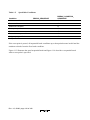
Section 2 Differences between the SH7410 and the Emulator ..........................163
Section 3 SH7410 Function Support .................................................................165
3.1
3.2
3.3
3.3.1
3.3.2
3.3.3
3.3.4
3.3.5
3.3.6
3.3.7
3.3.8
Operating Mode Setting .................................................................................................... 165
Memory Area .................................................................................................................... 167
3.2.1 Internal I/O Area.................................................................................................. 168
3.2.2 External Memory Area ........................................................................................ 168
Other Functions................................................................................................................. 168
Low-Power Mode (Sleep and Standby) ............................................................................ 168
Interrupts........................................................................................................................... 169
Control Input Signals (RES, WAIT, BREQ) .................................................................... 169
Serial Communication Interface ....................................................................................... 169
16-Bit Free-Running Timer (FRT).................................................................................... 169
DMAC .............................................................................................................................. 170
Hitachi User Debugging Interface (Hitachi-UDI)............................................................. 170
Bus State Controller .......................................................................................................... 170
Rev. 1.0, 09/00, page iii of xi
3.3.9 System Controller (SYSC)................................................................................................ 170
Section 4 User System Interface........................................................................171
Section 5 Troubleshooting.................................................................................179
5.1
5.2
Internal System Test.......................................................................................................... 179
Troubleshooting Procedure............................................................................................... 182
Section 6 Command Input and Display.............................................................185
6.1
6.2
Command Syntax.............................................................................................................. 185
6.1.1 Command Input Format....................................................................................... 185
6.1.2 Help Function ...................................................................................................... 185
6.1.3 Word Definition ................................................................................................... 186
Special Key Input.............................................................................................................. 187
6.2.1 Command Execution and Termination ............................................................... 187
6.2.2 Display Control.................................................................................................... 187
6.2.3 Command Re-entry.............................................................................................. 188
6.2.4 Cursor Control and Character Editing ................................................................. 188
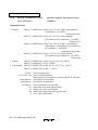
Section 7 Emulation Commands .......................................................................189
7.1
7.2
Overview........................................................................................................................... 189
Emulation Commands....................................................................................................... 191
7.2.1 .<register>............................................................................................................ 192
7.2.2 ABORT ................................................................................................................ 195
7.2.3 ALIAS.................................................................................................................. 196
7.2.4 ASSEMBLE......................................................................................................... 198
7.2.5 BACKGROUND_INTERRUPT.......................................................................... 200
7.2.6 BREAK................................................................................................................ 205
7.2.7 BREAK_CONDITION_A,B,C............................................................................ 208
7.2.8 BREAK_CONDITION_SEQUENCE ................................................................. 219
7.2.9 BREAK_CONDITION_UBC.............................................................................. 226
7.2.10 BREAK_SEQUENCE ......................................................................................... 232
7.2.11 CHECK................................................................................................................ 236
7.2.12 CLOCK................................................................................................................ 237
7.2.13 CONFIGURATION............................................................................................. 239
7.2.14 CONVERT........................................................................................................... 241
7.2.15 DATA_CHANGE................................................................................................ 243
7.2.16 DATA_SEARCH................................................................................................. 245
7.2.17 DISASSEMBLE .................................................................................................. 247
7.2.18 DUMP.................................................................................................................. 250
7.2.19 END ..................................................................................................................... 254
7.2.20 EXECUTION_MODE ......................................................................................... 255
7.2.21 FILL..................................................................................................................... 261
Rev. 1.0, 09/00, page iv of xi
7.2.22
7.2.23
7.2.24
7.2.25
7.2.26
7.2.27
7.2.28
7.2.29
7.2.30
7.2.31
7.2.32
7.2.33
7.2.34
7.2.35
7.2.36
7.2.37
7.2.38
7.2.39
7.2.40
7.2.41
7.2.42
7.2.43
7.2.44
7.2.45
7.2.46
GO........................................................................................................................ 263
HELP ................................................................................................................... 272
HISTORY ............................................................................................................ 275
ID ......................................................................................................................... 276
MAP..................................................................................................................... 277
MEMORY ........................................................................................................... 281
MODE.................................................................................................................. 284
MOVE.................................................................................................................. 286
MOVE_TO_RAM ............................................................................................... 287
PERFORMANCE_ANALYSIS1-8 ..................................................................... 289
QUIT.................................................................................................................... 299
RADIX................................................................................................................. 300
REGISTER .......................................................................................................... 302
RESET ................................................................................................................. 303
RESULT .............................................................................................................. 304
STATUS .............................................................................................................. 306
STEP .................................................................................................................... 308
STEP_INFORMATION ...................................................................................... 314
STEP_OVER ....................................................................................................... 317
TRACE ................................................................................................................ 321
TRACE_CONDITION_A,B,C ............................................................................ 328
TRACE_CONDITION_SEQUENCE.................................................................. 341
TRACE_DISPLAY_MODE ................................................................................ 349
TRACE_MODE................................................................................................... 352
TRACE_SEARCH............................................................................................... 355
Section 8 Data Transfer from Host Computer Connected by
RS-232C Interface ............................................................................................ 361
8.1
8.2
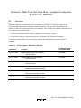
Overview........................................................................................................................... 361
Host-Computer Related Commands ................................................................................. 362
8.2.1 INTFC_LOAD..................................................................................................... 364
8.2.2 INTFC_SAVE...................................................................................................... 366
8.2.3 INTFC_VERIFY.................................................................................................. 368
8.2.4 LOAD .................................................................................................................. 370
8.2.5 SAVE ................................................................................................................... 372
8.2.6 VERIFY ............................................................................................................... 374
Section 9 Data Transfer from Host Computer Connected
by LAN Interface ...............................................................................377
9.1
9.2
Overview........................................................................................................................... 377
LAN Data Transfer ........................................................................................................... 379
9.2.1 Setting the Data Transfer Environment ............................................................... 379
9.2.2 Data Transfer ....................................................................................................... 380
Rev. 1.0, 09/00, page v of xi
9.3
9.2.3 Notes on FTP Interface ....................................................................................... 380
LAN Commands ............................................................................................................... 381
9.3.1 ASC...................................................................................................................... 383
9.3.2 BIN ...................................................................................................................... 384
9.3.3 BYE ..................................................................................................................... 385
9.3.4 CD........................................................................................................................ 386
9.3.5 CLOSE................................................................................................................. 387
9.3.6 FTP ...................................................................................................................... 388
9.3.7 LAN ..................................................................................................................... 390
9.3.8 LAN_HOST......................................................................................................... 391
9.3.9 LAN_LOAD ........................................................................................................ 392
9.3.10 LAN_SAVE......................................................................................................... 394
9.3.11 LAN_VERIFY..................................................................................................... 396
9.3.12 LS......................................................................................................................... 398
9.3.13 OPEN ................................................................................................................... 399
9.3.14 PWD..................................................................................................................... 401
9.3.15 ROUTER ............................................................................................................. 402
9.3.16 STA...................................................................................................................... 403
9.3.17 SUBNET .............................................................................................................. 404
9.3.18 LOGOUT ............................................................................................................. 405
Part III Appendix
Appendix A Connectors ....................................................................................409
A.1
A.2
A.3
A.4
Serial Connector................................................................................................................ 409
Parallel Connector............................................................................................................. 410
LAN Connector................................................................................................................. 412
Serial Interface Cable........................................................................................................ 414
Appendix B Emulator External Dimensions and Weight..................................417
Appendix C Connecting the Emulator to the User System ...............................419
C.1
C.2
C.3
Connecting to the User System ......................................................................................... 419
C.1.1 Connection Using the HS7410EBH82H.............................................................. 420
C.1.2 Connection Using the HS7410EBK82H.............................................................. 423
User Interface Pin Assignment.......................................................................................... 426
Precautions for User System Connection.......................................................................... 430
Appendix D Memory Map ................................................................................431
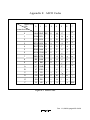
Appendix E ASCII Codes..................................................................................435
Rev. 1.0, 09/00, page vi of xi
Figures
Part I E8000 Guide
Figure 1.1
Figure 2.1
Figure 2.2
Figure 2.3
Figure 2.4
Figure 2.5
Figure 2.6
Figure 2.7
Figure 2.8
Emulator for the SH7410 ......................................................................................... 4
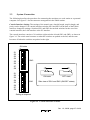
Emulator Hardware Components ............................................................................. 11
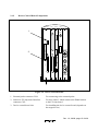
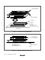
E8000 Station Front Panel........................................................................................ 12
E8000 Station Rear Panel......................................................................................... 13
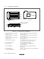
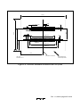
Device Control Board............................................................................................... 15
EV-Chip Board......................................................................................................... 16
Emulator Software Components .............................................................................. 18
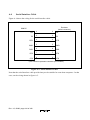
System Configuration Using a LAN Interface ......................................................... 20
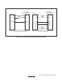
System Configuration Using an RS-232C or Bidirectional
Parallel Interface ...................................................................................................... 21
Figure 2.9 System Configuration Using a PC Interface Board.................................................. 22
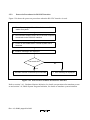
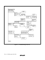
Figure 3.1 Emulator Preparation Flow Chart............................................................................. 24
Figure 3.2 Connecting the Device Control Board ..................................................................... 26
Figure 3.3 Connecting Trace Cables to the E8000 Station ........................................................ 29
Figure 3.4 Connecting Trace Cables to the EV-Chip Board...................................................... 30
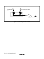
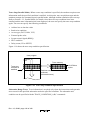
Figure 3.5 External Probe Connector ........................................................................................ 31
Figure 3.6 Installing the Crystal Oscillator................................................................................ 33
Figure 3.7 Connecting the System Ground................................................................................ 35
Figure 3.8 Connecting the Frame Ground ................................................................................. 36
Figure 3.9 Console Interface Switches ...................................................................................... 37
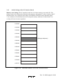
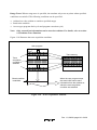
Figure 3.10 Allocatable Memory Area of PC Interface Board .................................................. 41
Figure 3.11 PC Interface Board Switch ..................................................................................... 42
Figure 3.12 Installing the PC Interface Board ........................................................................... 43
Figure 3.13 Connecting the E8000 Station to the PC Interface Board ...................................... 44
Figure 3.14 Ethernet Interface ................................................................................................... 49
Figure 3.15 Cheapernet Interface .............................................................................................. 50
Figure 3.16 RS-232C Interface.................................................................................................. 51
Figure 3.17 Bidirectional Parallel Interface............................................................................... 52
Figure 3.18 IPW Window.......................................................................................................... 53
Figure 3.19 File Menu and Setting Menu .................................................................................. 54
Figure 3.20 Communication Setting Box .................................................................................. 55
Figure 3.21 Screen Setting Box ................................................................................................. 55
Figure 3.22 Exit Menu............................................................................................................... 56
Figure 3.23 Power-On Procedures for LAN Interface............................................................... 60
Figure 3.24 Power-On Procedures for RS-232C Interface ........................................................ 66
Figure 3.25 E8000 System Disk ................................................................................................ 79
Rev. 1.0, 09/00, page vii of xi
Part II Emulator Function Guide
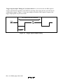
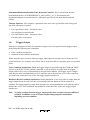
Figure 1.1 Cycle Reset Mode .................................................................................................... 119
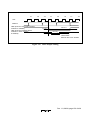
Figure 1.2 Trigger Signal Output Timing.................................................................................. 120
Figure 1.3 Transition to Parallel Mode...................................................................................... 121
Figure 1.4 Parallel Mode ........................................................................................................... 122
Figure 1.5 Break with Address Bus Value................................................................................. 126
Figure 1.6 Break with Data Bus Value ...................................................................................... 127
Figure 1.7 Break with Read/Write .............................................................................................127
Figure 1.8 Break with Delay Count Specification ..................................................................... 128
Figure 1.9 Break with Delay Count Specification ..................................................................... 129
Figure 1.10 Break with PC Value Specification ........................................................................ 130
Figure 1.11 Break with Sequential Specification ...................................................................... 131
Figure 1.12 Normal Break (Software Break)............................................................................. 133
Figure 1.13 Sequential Break .................................................................................................... 135
Figure 1.14 Sequential Break (Reset Point Specification)......................................................... 136
Figure 1.15 External Probe Signal Trace................................................................................... 138
Figure 1.16 Free Trace Execution ............................................................................................. 139
Figure 1.17 Subroutine Trace Specification .............................................................................. 140
Figure 1.18 Trace Acquisition Condition .................................................................................. 141
Figure 1.19 Trace Stop Condition Specification........................................................................ 142
Figure 1.20 Subroutine Display ................................................................................................. 145
Figure 1.21 Normal Mode Time Measurement Range .............................................................. 146
Figure 1.22 Time Interval Measurement Mode 1 ...................................................................... 146
Figure 1.23 Time Interval Measurement Mode 2 ...................................................................... 147
Figure 1.24 Time Measurement Mode 1 ................................................................................... 149
Figure 1.25 Time Measurement Mode 2 ................................................................................... 150
Figure 1.26 Time Measurement Mode 3 ................................................................................... 151
Figure 1.27 Pulse Output Timing .............................................................................................. 153
Figure 1.28 Assembly Function................................................................................................. 158
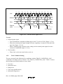
Figure 4.1 Basic Bus Cycle........................................................................................................ 172
Figure 4.2 Control Signal Timing.............................................................................................. 173
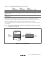
Figure 4.3 User System Interface Circuits................................................................................. 174
Figure 5.1 Troubleshooting PAD .............................................................................................. 183
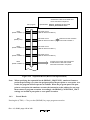
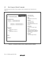
Figure 7.1 Emulation Command Description Format................................................................ 191
Figure 7.2 Display Range Specified by Pointers ....................................................................... 322
Figure 8.1 Description Format of Host-Computer Related Command ...................................... 362
Figure 9.1 LAN Command Description Format ........................................................................ 381
Part III Appendix
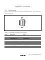
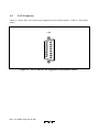
Figure A.1 Serial Connector Pin Alignment at the Emulator Station ........................................ 409
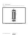
Figure A.2 Parallel Connector Pin Alignment at the Emulator Station ..................................... 410
Rev. 1.0, 09/00, page viii of xi
Figure A.3
Figure A.4
Figure A.5
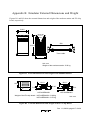
Figure B.1
Figure B.2
Figure C.1
Figure C.2
Figure C.3
Figure C.4
Figure C.5
Figure C.6
Figure C.7
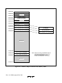
Figure D.1
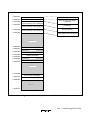
Figure D.2
Figure E.1
LAN Connector Pin Alignment at the Emulator Station ......................................... 412
Serial Interface Cable .............................................................................................. 414
Serial Interface Cable (Using Other Cables) ........................................................... 415
External Dimensions and Weight of the E8000 Emulator....................................... 417
External Dimensions and Weight of the EV-Chip Board ........................................ 417
Connection of the HS7410EBH82H........................................................................ 421
Component Installation Size Restriction ................................................................. 421
Connector Installation Location on the User System............................................... 422
Connection of the HS7410EBK82H........................................................................ 424
Component Installation Size Restriction ................................................................. 424
Connector Installation Location on the User System............................................... 425
Examples of Securing the Emulator Station ............................................................ 430
Memory Map for Internal CS0 Memory Mode ....................................................... 432
Memory Map for External CS0 Memory Mode...................................................... 433
ASCII Codes ............................................................................................................ 435
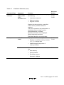
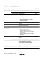
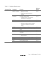
Tables
Part I E8000 Guide
Table 1.1
Table 1.2
Table 1.3
Table 1.4
Table 2.1
Table 3.1
Table 3.2
Table 3.3
Table 3.4
Table 3.5
Table 3.6
Table 3.7
Table 3.8
Table 3.9
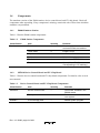
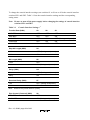
Environmental Conditions...................................................................................... 7
E8000 Station Components.................................................................................... 8
Device Control Board and EV-Chip Board Components....................................... 8
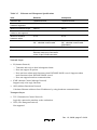
Optional Component Specifications....................................................................... 9
Contents of E8000 System Disk............................................................................. 19
Console Interface Settings...................................................................................... 38
PC Interface Board Specifications.......................................................................... 40
Switch Settings for Memory Areas ........................................................................ 42
Personal Computer Interface Specifications .......................................................... 45
Ethernet and Cheapernet Specifications................................................................. 47
Recommended Transceiver and Transceiver Cable ............................................... 49
Recommended BNC T-Type Connector and Thin-Wire Cable ............................. 50
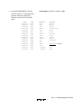
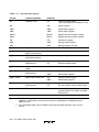
Emulator Monitor Commands................................................................................ 67
Flash Memory Management Tool Commands ....................................................... 69
Part II Emulator Function Guide
Table 1.1
Table 1.2
Table 1.3
Table 1.4
Table 1.5
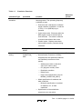
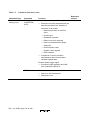
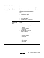
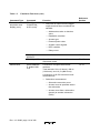
SH7410 Functions .................................................................................................. 109
Emulation Functions .............................................................................................. 111
Host Computer Interface Functions ....................................................................... 118
Specifiable Hardware Break Conditions ................................................................ 125
Specifiable Conditions ........................................................................................... 134
Rev. 1.0, 09/00, page ix of xi
Table 1.6
Table 1.7
Table 1.8
Table 1.9
Table 1.10
Table 1.11
Table 2.1
Table 3.1
Table 3.2
Table 4.1
Table 7.1
Table 7.2
Table 7.3
Table 7.4
Table 7.5
Table 7.6
Table 7.7
Table 7.8
Table 7.9
Table 7.10
Table 7.11
Table 7.12
Table 7.13
Table 7.14
Table 7.15
Table 7.16
Table 7.17
Table 7.18
Table 7.19
Table 7.20
Table 7.21
Table 7.22
Table 7.23
Table 7.24
Table 7.25
Table 7.26
Table 7.27
Table 7.28
Table 7.29
Table 7.30
Table 7.31
Table 7.32
Maximum Specifiable Numbers in Trace Mode .................................................... 139
Maximum Number of Measurable Subroutines ..................................................... 148
Execution Status Display........................................................................................ 155
Operating Status Display........................................................................................ 156
Assembler Directives ............................................................................................. 159
Operand Descriptions............................................................................................. 160
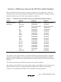
Differences between Initial Values of the SH7410 and Emulator Registers.......... 163
SH7410 Operating Mode Selection........................................................................ 166
CS0 Area Bus Width Selection .............................................................................. 167
Bus Timing (Bus Clock: 30 MHz) ......................................................................... 171
Emulation Commands ........................................................................................... 189
Subcommands for Line Assembly ........................................................................ 199
Causes of BACKGROUND_INTERRUPT Command Termination ..................... 202
Maximum Conditions for Each Break Type .......................................................... 208
Specifiable Conditions (BREAK_CONDITION_A1-A8) .................................... 209
Specifiable Conditions (BREAK_CONDITION_B1-B8) ..................................... 211
Specifiable Conditions (BREAK_CONDITION_C1-C8) ..................................... 213
Address Mask Specifications (BREAK_CONDITION_A,B,C) ............................ 215
Mask Specifications (BREAK_CONDITION_A,B,C) .......................................... 215
Specifiable Pass Point Conditions (BREAK_CONDITION_
SEQUENCE).......................................................................................................... 220
Address Mask Specifications (BREAK_CONDITION_SEQUENCE).................. 223
Mask Specifications (BREAK_CONDITION_SEQUENCE)................................ 224
Specifiable Conditions (BREAK_CONDITION_UBC1) ..................................... 227
Specifiable Conditions (BREAK_CONDITION_UBC2) ..................................... 228
Mask Specifications (BREAK_CONDITION_UBC1,2) ....................................... 229
SH7410 Pin Test .................................................................................................... 236
Saved Configuration Information........................................................................... 239
Cycle Reset Times ................................................................................................. 265
Restrictions for Realtime Emulation Modes ......................................................... 266
Causes of GO Command Termination ................................................................... 268
Execution Status Display ....................................................................................... 269
MEMORY Command Options .............................................................................. 282
Operating Mode Selection Pin Status and Display ................................................ 285
Measurement Modes for Each Command .............................................................. 292
Radix and Input Examples .................................................................................... 300
DSR Register Setting Bits ..................................................................................... 302
Causes of STEP Command Termination ............................................................... 310
Causes of STEP_OVER Command Termination .................................................. 319
MA Display ........................................................................................................... 324
R/W Display .......................................................................................................... 324
ST Display ............................................................................................................. 324
Vcc Voltage Display ............................................................................................. 325
Rev. 1.0, 09/00, page x of xi
Table 7.33
Table 7.34
Table 7.35
Table 7.36
Table 7.37
Table 7.38
Table 7.39
Table 7.40
Table 7.41
Table 7.42
Table 7.43
Table 7.44
Table 7.45
Table 8.1
Table 9.1
Specifiable Conditions in Each Trace Mode .......................................................... 330
Specifiable Conditions (TRACE_CONDITION_A) ............................................. 331
Specifiable Conditions (TRACE_CONDITION_B) ............................................. 333
Specifiable Conditions (TRACE_CONDITION_C) ............................................. 335
Address Mask Specifications (TRACE_CONDITION_A,B,C)............................. 337
Mask Specifications (TRACE_CONDITION_A,B,C) .......................................... 337
Sequential Trace Stop Conditions (TRACE_CONDITION_
SEQUENCE).......................................................................................................... 342
Address Mask Specifications (TRACE_CONDITION_SEQUENCE) .................. 345
Mask Specifications (TRACE_CONDITION_SEQUENCE) ................................ 345
Shipment Defaults of TRACE_DISPLAY_MODE Command ............................. 350
Display of Minimum Time Stamp Unit ................................................................. 354
Specifiable Conditions (TRACE_SEARCH) ........................................................ 356
Mask Specifications (TRACE_SEARCH) ............................................................ 359
Host-Computer Related Commands ...................................................................... 361
LAN Commands ................................................................................................... 378
Part III Appendix
Table A.1
Table A.2
Table A.3
Table C.1
Table C.2
Table C.3
Table C.4
Signal Names and Usage of Serial Connector........................................................ 409
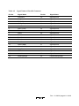
Signal Names of Parallel Connector....................................................................... 411
Signal Names.......................................................................................................... 413
EV-Chip Boards and User Interfaces ..................................................................... 419
Pin Assignment of the HS7410EBH82H ............................................................... 426
Pin Assignment of the HS7410EBK82H User Interface (USER I/F1) .................. 428
Pin Assignment of the HS7410EBK82H User Interface (USER I/F2) .................. 429
Rev. 1.0, 09/00, page xi of xi
Part I E8000 Guide
Rev. 1.0, 09/00, page 2 of 436
Section 1 Overview
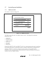
1.1
Overview
This system is an efficient software and hardware development support tool for application
systems using the SH7410 microcomputer developed by Hitachi, Ltd. The SH7410 MCU contains
the following components on a single chip:
• DSP
• High-speed CPU
• Timer
• Serial communication interface
• SIO
• DMAC
• Hitachi-UDI (Hitachi-User-Debug-Interface) port
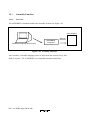
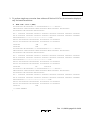
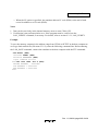
The emulator operates in place of the SH7410 MCU and performs realtime emulation of the user
system. The emulator also provides functions for efficient hardware and software debugging.
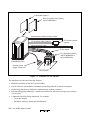
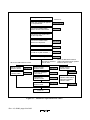
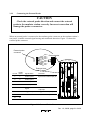
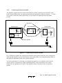
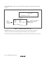
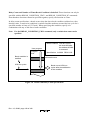
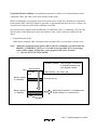
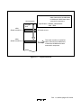
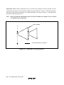
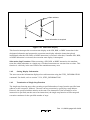
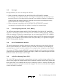
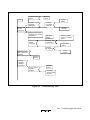
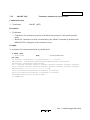
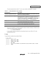
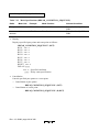
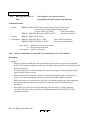
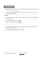
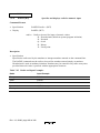
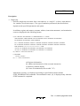
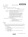
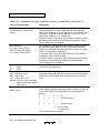
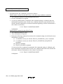
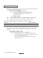
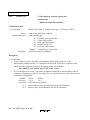
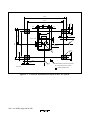
The emulator consists of an emulator (E8000) station, an SH7410 device control board, and an
evaluation chip board (hereafter referred to as an EV-chip board), as shown in figure 1.1. The EVchip board is directly installed onto the user system.
Rev. 1.0, 09/00, page 3 of 436
LAN board (option)
Device control board (option)
(HS7410EDD82H)
Bidirectional parallel-interface cable
PC interface board
(option)
PC interface cable (option)
HITACHI
E8000
Serial-interface cable
Trace cables
EV-chip board (option)
(HS7410EBH82H or
HS7410EBK82H)
POWER
RUN
E8000 station
(HS8000EST02H)
External probe
trigger output pins
User system
Figure 1.1 Emulator for the SH7410
The emulator provides the following features:
• Realtime emulation of the SH7410 at 60 MHz
• A wide selection of emulation commands, promoting efficient system development
• On-line help functions to facilitate command usage without a manual
• Efficient debugging enabled by variable break functions and a mass-storage trace memory
(128 kcycles)
• Command execution during emulation, for example
Trace data display
Emulation memory display and modification
Rev. 1.0, 09/00, page 4 of 436
• Measurement of subroutine execution time and count for evaluating the execution efficiency
of user programs
• 4-Mbyte standard emulation memory for use as a substitute user-system memory
• An optional LAN board for interfacing with workstations, enabling high-speed downloading
(1 Mbyte/min) of user programs
The LAN board contains Ethernet* (10BASE5) and Cheapernet (10BASE2) interfaces.
• SH7410 Integration Manager (option) can be loaded into the workstation to enable:
Graphic display operations in a multi-window environment
Source level debugging
Graphic display of trace information
• A PC board for interfacing with a PC, enabling high-speed downloading (1 Mbyte/min) of
user programs
• SH7410 E8000 Hitachi Debugging Interface (option) can be loaded into the PC to enable:
Graphic display operations in a multi-window environment
Source-level debugging
Note: Ethernet is a registered trademark of Xerox Corporation.
Rev. 1.0, 09/00, page 5 of 436
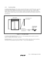
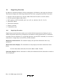
1.2
Warnings
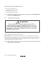
CAUTION
READ the following warnings before using the emulator
product. Incorrect operation will damage the user system and
the emulator product. The USER PROGRAM will be LOST.
1. Check all components with the component list after unpacking the emulator.
2. Never place heavy objects on the casing.
3. Observe the following conditions in the area where the emulator is to be used:
Make sure that the internal cooling fans on the sides of the E8000 station must be at least
20 cm (8”) away from walls or other equipment.
Keep out of direct sunlight or heat. Refer to section 1.3, Environmental Conditions.
Use in an environment with constant temperature and humidity.
Protect the emulator from dust.
Avoid subjecting the emulator to excessive vibration. Refer to section 1.3, Environmental
Conditions.
4. Protect the emulator from excessive impacts and stresses.
5. Before using the emulator’s power supply, check its specifications such as power output,
voltage, and frequency. For details of the power supply, refer to section 1.3, Environmental
Conditions.
6. When moving the emulator, take care not to vibrate or otherwise damage it.
7. After connecting the cable, check that it is connected correctly. For details, refer to section 3,
Preparation before Use.
8. Supply power to the emulator and connected parts after connecting all cables. Cables must not
be connected or removed while the power is on.
9. For details on differences between the SH7410 and the emulator, refer to section 2,
Differences between the SH7410 and the Emulator in Part II, Emulator Function Guide.
Rev. 1.0, 09/00, page 6 of 436
1.3
Environmental Conditions
CAUTION
The following environmental conditions must be satisfied
when using the emulator. Failure to do so will damage the user
system and the emulator. The USER PROGRAM will be LOST.
Observe the conditions listed in table 1.1 when using the emulator.
Table 1.1
Environmental Conditions
Item
Specifications
Temperature
Operating:
+10 to +35°C
Storage:
–10 to +50°C
Operating:
35 to 80% RH, no condensation
Storage:
35 to 80% RH, no condensation
Humidity
Vibration
2
Operating:
2.45 m/s max.
Storage:
4.9 m/s max.
2
2
Transportation: 14.7 m/s max.
AC input power
Ambient gases
Voltage:
AC100-120 V/200-240 V ± 10%
Frequency:
50/60 Hz
Power consumption:
200 VA
There must be no corrosive gases present.
Rev. 1.0, 09/00, page 7 of 436
1.4
Components
The emulator consists of the E8000 station, device control board, and EV-chip board. Check all
components after unpacking. If any component is missing, contact the sales office from which the
emulator was purchased.
1.4.1
E8000 Emulator Station
Table 1.2 lists the E8000 station components.
Table 1.2
E8000 Station Components
Classification
Item
Quantity
Remarks
Hardware
E8000 station
1
Power supply, control board,
and trace board are installed.
Trace cable
3
Length: 50 cm
AC power cable
1
UL cable or B5 cable
Serial cable
1
RS-232C interface
Parallel cable
1
Conforms to IEEE-P1284.
Fuse
1
Spare (3 A or T3.15A
corresponding to CE marking )
1.4.2
SH7410 Device Control Board and EV-Chip Board
Table 1.3 lists the device control board and EV-chip board components. For details, refer to each
users manual.
Table 1.3
Device Control Board and EV-Chip Board Components
Classification
Item
Quantity
Remarks
Hardware
Device control board
1
One board, installed in the
E8000 station
EV-chip board
1
Two boards, installed in the
user system
3.5-inch floppy disk
1
E8000 system program
Software
Rev. 1.0, 09/00, page 8 of 436
1.4.3
Options
In addition to the E8000 station and EV-chip board components, the options listed in table 1.4 are
also available. Refer to each option manual for details on these optional components.
Table 1.4
Optional Component Specifications
Item
Model Name
Specifications
LAN board
HS7000ELN01H
•
TCP/IP communications protocol
HS7000ELN02H
•
Ethernet (10BASE5)
•
Cheapernet (10BASE2)
PC interface board
HS6000EII01H
ISA bus
Rev. 1.0, 09/00, page 9 of 436
Rev. 1.0, 09/00, page 10 of 436
Section 2 Components
2.1
Emulator Hardware Components
The emulator consists of an E8000 station, an SH7410 device control board, and an SH7410 EVchip board, as shown in figure 2.1. The emulator station includes a serial-interface cable (RS232C) and a parallel-interface cable (conforms to IEEE-P1284 and is for the ECP mode) for the
host computer interface. By installing a LAN board (option), the emulator can be connected to a
workstation via the LAN interface. By installing a PC interface board (option) to a PC to be used,
the emulator can be connected to the PC via the ISA bus.
LAN board (option)
Device control board (option)
(HS7410EDD82H)
Bidirectional parallel-interface cable
PC interface board
(option)
PC interface cable (option)
HITACHI
E8000
Serial-interface cable
Trace cables
EV-chip board (option)
(HS7410EBH82H or
HS7410EBK82H)
POWER
RUN
E8000 station
(HS8000EST02H)
External probe
trigger output pins
User system
Figure 2.1 Emulator Hardware Components
Rev. 1.0, 09/00, page 11 of 436
2.1.1
E8000 Station Components
Front Panel:
HITACHI
E8000
1
POWER
2
RUN
Figure 2.2 E8000 Station Front Panel
1. POWER lamp:
Is lit up when the E8000 station power is on.
2. RUN lamp:
Is lit up when the user program is running.
Rev. 1.0, 09/00, page 12 of 436
Rear Panel:
DCONT
TRC
CONT
TRC
CONT
6
LAN
4
BNC
PARALLEL
10
CN1
5
LAN
7
POWER
PCIF
8
SW2
250V 3A
1
CN2
SW1
AC INPUT
SERIAL
2
11
AC100-120V/
AC200-240V
2A 50/60Hz
9
15
14
13
3
12
Figure 2.3 E8000 Station Rear Panel
Rev. 1.0, 09/00, page 13 of 436
1. Power switch:
Turning this switch to I (input) supplies power to
the emulator (E8000 station and EV-chip board).
2. Fuse box:
Contains a 3-A 250-V AC fuse or T3.15A.
3. AC power connector:
For a AC100-120 V/200-240 V power supply.
4. Cheapernet connector:
For a Cheapernet cable. Marked BNC.
5. Ethernet connector:
For an Ethernet cable. Marked LAN.
6. Parallel-interface connector:
For a parallel-interface cable with the host PCIF
board. Conforms to IEEE-P1284 (ECP mode).
Marked PARALLEL.
7. PC interface cable connector:
For the PC interface cable which connects the
PC to the E8000 station. Marked PCIF.
8. Host interface switches:
For selecting the host interface. Specifies the
connection of the LAN interface, RS-232C
interface, or PC I/F board. When the RS-232C
interface is used, the data-bit length, stop-bit
length, or parity-setting transfer rate can be
switched. Marked SW1 and SW2.
9. Serial-interface connector:
For RS-232C communication with a host PC.
Marked SERIAL.
10. Station to EV-chip board interface
connector CN1:
For trace cable 1 which connects the E8000 station
to the EV-chip board.
11. Station to EV-chip board interface
connector CN2:
For trace cable 2 which connects the E8000 station
to the EV-chip board.
12. LAN-board slot:
For installing the optional LAN board.
13. Control board slot:
For installing the control board.
14. Trace board slot:
For installing the trace board.
15. Device control board slot:
For installing the device control board (depends on
the target device).
Rev. 1.0, 09/00, page 14 of 436
2.1.2
Device Control Board Components
DCONT
TRC
CONT
TRC
CONT
DCONT
1
LAN
BNC
PARALLEL
CN1
CN4
HS7410EDD82H
POWER
PCIF
2
LAN
SW2
250V 3A
SW1
AC INPUT
CN2
CN3
SERIAL
AC100-120V/
AC200-240V
2A 50/60Hz
3
Figure 2.4 Device Control Board
1. External probe connector CN4:
For connecting to the external probe.
2. Station to EV-chip board interface
connector CN3:
For trace cable 3 which connects the E8000 station
to the EV-chip board.
3. Device control board slot:
For installing the device control board (depends on
the target device).
Rev. 1.0, 09/00, page 15 of 436
2.1.3
EV-Chip Board Components
CN3
CN2
1
5
2
CN1
X0
X0
3
X1
X1
4
Pin-1 mark
Bottom view
Top view
Station to EV-chip board
interface connectors
6
7
8
Side view
Figure 2.5 EV-Chip Board (HS7410EBH82H) *1
1. Station to EV-chip board interface
connector CN3:
For trace cable 3 which connects the emulator to
the EV-chip board.
2. Station to EV-chip board interface
connector CN2:
For trace cable 2 which connects the emulator to
the EV-chip board.
3. Station to EV-chip board interface
connector CN1:
For trace cable 1 which connects the emulator to
the EV-chip board.
4. Crystal oscillator terminals:
For installing a crystal oscillator to be used as
an external clock source for the SH7410.
5. User-system connector:
For connecting the user system.
6. Board connector:
For connecting HS7410PWB20H and
HS7410PWB30H.
7. HS7410PWB20H:
Includes connectors for interfacing with the
E8000 station.
8. HS7410PWB30H
(or HS7410PWB40H*2):
Includes connectors (QFP-176) for interfacing with
the user system.
Rev. 1.0, 09/00, page 16 of 436
Notes: 1. For the EV-chip board, there are a QFP176 IC socket type (HS7410EBH82H) and
a two 100-pin connector type (HS7410EBK82H), which can be selected in
accordance with the user application.
2. The HS7410PWB40H has a connector (2 x 100-pin) to be connected to the user
system.
Rev. 1.0, 09/00, page 17 of 436
2.2
Emulator Software Components
The emulator’s software components are illustrated in figure 2.6. The device control board
contains a 3.5-inch floppy disk. The system disk files are described in table 2.1.
HITACHI
E8000
E8000 system program
POWER
Loadable file types:
¥ S-type files
¥ HEX-type files
¥ SYSROF-type files
RUN
Interface software
C compiler
Cross assembler
Linkage editor
Personal computer
Figure 2.6 Emulator Software Components
Rev. 1.0, 09/00, page 18 of 436
Table 2.1
Contents of E8000 System Disk
File Name
Contents
Description
E8000.SYS
E8000 system program
Controls the EV-chip board and processes
commands, such as emulation commands.
Loaded into the emulator memory.
SHDCT741.SYS
SH7410 control program
Controls the SH7410 in the EV-chip board.
Loaded into the emulator memory.
SHCNF741.SYS
Configuration file
Contains SH7410 operating mode and MAP
information.
IPW.EXE
Interface program
Operates on the Microsoft Windows95 of the
PC and communicates with the emulator.
DIAG.SYS
Diagnostic program
Loaded into the emulator station memory for
testing and maintenance.
SETUP.CC*
Load file
Loads files E8000.SYS, SHDCT741.SYS, and
SHCNF741.SYS to the emulator memory.
Note:
See section 3.7, System Program Installation.
Rev. 1.0, 09/00, page 19 of 436
2.3
System Configuration
The E8000 station can be connected to the host computer via a LAN interface (optional LAN
board), an RS-232C interface, a bidirectional parallel interface, or a PC interface board.
2.3.1
System Configuration Using a LAN Interface
By installing an optional LAN board in the E8000 station, the emulator can communicate with a
workstation using a LAN interface. The LAN board contains connectors for both Cheapernet
(10BASE2) and Ethernet (10BASE5). The system configuration using a LAN interface is shown
in figure 2.7.
Cheapernet Interface
Workstation
Ethernet Interface
E8000
station
E8000
station
BNC
BNC
LAN
LAN
Workstation
Figure 2.7 System Configuration Using a LAN Interface
Cheapernet Interface: This is achieved by connecting a coaxial cable (referred to as the
Cheapernet thin-wire cable) between the BNC connector on the LAN board and the workstation.
Ethernet Interface: This is achieved by connecting transceivers and transceiver cables between
the D-SUB connector on the LAN board and the workstation.
Rev. 1.0, 09/00, page 20 of 436
2.3.2
System Configuration Using an RS-232C or Bidirectional Parallel Interface
Using an RS-232C interface or a bidirectional parallel interface, the E8000 station can be
connected to a personal computer. Figure 2.8 shows the system configuration using the RS-232C
or bidirectional parallel interface.
RS-232C Interface
Personal computer
Bidirectional Parallel Interface
E8000
station
E8000
station
Personal computer
SERIAL
SERIAL
PARALLEL
PARALLEL
Figure 2.8 System Configuration Using an RS-232C or Bidirectional Parallel Interface
Rev. 1.0, 09/00, page 21 of 436
2.3.3
System Configuration Using a PC Interface Board
The E8000 station can be connected to a personal computer via a PC interface board. Install the
PC interface board to the extension slot of the ISA bus specification in a PC, and connect the
interface cable supplied with the PC interface board to the E8000 station. Figure 2.9 shows the
system configuration using the PC interface board.
PC interface board
E8000 station
PCIF
Personal computer
Figure 2.9 System Configuration Using a PC Interface Board
Rev. 1.0, 09/00, page 22 of 436
Section 3 Preparation before Use
3.1
Emulator Preparation
CAUTION
Read the reference sections shaded in figure 3.1 and the
following warnings before using the emulator. Incorrect operation
will damage the user system and the emulator. The USER
PROGRAM will be LOST.
Unpack the emulator and prepare it for use as follows:
Rev. 1.0, 09/00, page 23 of 436
Unpack the emulator.
Reference:
Check the components against
the component list.
Component list
Connect the E8000 station
and the device control board.
Sec. 3.2.1
Connect the user system and
the EV-chip board.
Connect the E8000 station
and the EV-chip board.
Sec. 3.2.2
Connect the external probe.
Sec. 3.2.3
Select the clock.
(Install the crystal oscillator.)
Sec. 3.2.4
Connect the system ground.
Sec. 3.2.5
When the LAN interface is used.
When the PC interface
board is used.
Set the console
interface switch.
Sec. 3.3
Set the console
interface switch.
Sec. 3.3
Connect the LAN
interface cable.
Sec. 3.3.2
Set the PC interface
board switch.
Sec. 3.3.2
Install the PC
interface board.
Sec. 3.3.3
Connect the PC
interface cable.
Sec. 3.3.4
When the RS-232C interface
cable or/and bidirectional parallel
interface cable is used.
Set the console
interface switch.
Sec. 3.3
Connect the RS-232C
interface cable or/and
bidirectional parallel
interface cable.
Power on.
Figure 3.1 Emulator Preparation Flow Chart
Rev. 1.0, 09/00, page 24 of 436
Sec. 3.3.7
3.2
Emulator Connection
3.2.1
Connecting the Device Control Board
At shipment, the device control board is packed separately from the E8000 station. Connect the
device control board to the E8000 station according to the following procedure. Also, use the
following procedure to connect them after remove the device control board from the E8000
station to change the device control board.
WARNING
Always switch OFF the emulator and user system before
connecting or disconnecting any CABLES. Failure to do so will
result in a FIRE HAZARD and will damage the user system and
the emulator or will result in PERSONAL INJURY. The USER
PROGRAM will be LOST.
1. Check that the emulator power switch is turned off. Ensure that the power lamp on the left side
of the E8000 station’s front panel is not lit.
2. Remove the AC power cable of the E8000 station from the outlet (if the cable is connected to
the outlet).
3. Remove the back panel from the E8000 station. For the slot to which the device control board
is to be connected, DCONT is marked.
4. Connect the device control board to the E8000 station. When connecting the board, prevent
the upper or lower side of the board from lifting off the connector. Alternately tighten the
screws on both sides of the board.
Rev. 1.0, 09/00, page 25 of 436
DCONT
TRC
CONT LAN
TRC
CONT
PARALLEL
Device control board
CN1
DCONT
POWER
PCIF
SW2
SW1
CN4
AC INPUT
SERIAL
CN2
HS7410EDD82H
250V 3A
AC100-120V/
AC200-240V
2A 50/60Hz
CN3
E8000 station rear panel
Figure 3.2 Connecting the Device Control Board
Rev. 1.0, 09/00, page 26 of 436
3.2.2
Connecting the EV-Chip Board
At shipment, the EV-chip board is packed separately from the E8000 station. Use the following
procedure to connect the EV-chip board to the E8000 station, or to disconnect them when moving
the emulator:
WARNING
Always switch OFF the emulator and user system before
connecting or disconnecting any CABLES. Failure to do so will
result in a FIRE HAZARD and will damage the user system and
the emulator or will result in PERSONAL INJURY. The USER
PROGRAM will be LOST.
1. Check that the emulator power switch is turned off. Ensure that the power lamp on the left side
of the E8000 station’s front panel is not lit.
2. Remove the AC power cable of the E8000 station from the outlet (if the cable is connected to
the outlet).
Rev. 1.0, 09/00, page 27 of 436
WARNING
When connecting the cable, ensure that the upper (A) or
lower (B) side of the cable does not lift off the connector.
Alternately tighten the screws on both sides of the cable while
gradually pushing the cable toward the connector.
Failure to do so will result in a FIRE HAZARD, damage the user
system and emulator, and will result in PERSONAL INJURY.
The USER PROGRAM will be LOST.
E8000
station
A
B
E8000
station
A
B
3. Connect the trace cables into the station to EV-chip board interface connectors (CN1, CN2,
and CN3) on the E8000 station’s rear panel. Confirm that the shape of the trace-cable plug
matches that of the station to EV-chip board interface connector before connecting. Also note
which trace cable is connected to which E8000-station connector so that the other end of the
trace cable is connected to the matching connector number on the EV-chip board. After the
connection is completed, alternately tighten the screws on both sides of the trace cable to
prevent the upper or lower side of the trace cable from lifting off the connector. Figure 3.3
shows how to correctly connect the trace cables to the E8000 station connectors.
Rev. 1.0, 09/00, page 28 of 436
CN1: red
CN1
CN2: yellow
CN3: blue
CN2
CN3
Colors of the station to EV-chip
board interface connectors: red,
yellow, and blue seals on the panel
CN1: red
Colors of the screws
on the trace cables
E8000 station rear panel
CN2: yellow
CN3: blue
Figure 3.3 Connecting Trace Cables to the E8000 Station
Note: At shipment, the trace cable screws are colored to prevent an insertion error (CN1:
red, CN2: yellow, CN3: blue). In addition, trace cables CN2 and CN3 to be connected
to the E8000 station are bound into a bundle, and trace cables CN1, CN2, and CN3 to
be connected to the EV-chip board are bound into a bundle. Check for the number of
cables bound into a bundle and the colors for connectors when connecting the cables.
Rev. 1.0, 09/00, page 29 of 436
WARNING
Make sure the connector shapes and numbers are correctly
matched when connecting trace cables to the station to EV-chip
interface connectors. Failure to do so will damage the connectors.
4. Connect the trace cables to the station to EV-chip board interface connectors CN1, CN2, and
CN3 on the EV-chip board. Confirm that each trace cable connected to a connector on the
E8000 station is also connected to its corresponding station to EV-chip board interface
connector on the EV-chip board. Connect the cables using the same method as in step 3.
Figure 3.4 shows how to connect the trace cables to the EV-chip board interface connectors.
CN3: blue
CN2: yellow
CN3
Trace cable CN1
CN2
CN1
Trace cable CN3
Trace cable CN2
CN1: red
Station to EV-chip board
interface connector CN1
Station to EV-chip board
interface connector CN3
User system
Station to EV-chip board
interface connector CN2
Figure 3.4 Connecting Trace Cables to the EV-Chip Board
Note: For the connection between the EV-chip board and the user system, refer to section
3, Connecting the EV-Chip Board to the User System, in the Evaluation Chip Board
(HS7410EBH82H, HS7410EBK82H) User’s Manual.
Rev. 1.0, 09/00, page 30 of 436
3.2.3
Connecting the External Probe
CAUTION
Check the external probe direction and connect the external
probe to the emulator station correctly. Incorrect connection will
damage the probe or connector.
When an external probe is connected to the emulator probe connector on the emulator station’s
rear panel, it enables external signal tracing and multibreak detection. Figure 3.5 shows the
external probe connector.
External probe
connector
CN4
Pin 8
Pin 7
Pin 6
Pin 5
Pin 4
Pin 3
Pin 2
Pin 1
External probe
Synchronous break input pin
1
Probe input 0
2
2
Probe input 1
3
3
Probe input 2
4
4
Probe input 3
5
5
RUN/break status
signal
RUN state identification
output pin
6
T
Trigger output
Trigger mode output pin
7
G
GND
GND connection pin
8
G
CONT
LAN
POWER
PCIF
1
TRC
LAN
PARALLEL
Remarks
CONT
CN1
Signal Name
TRC
BNC
CN4
Probe
Pin No. Name
DCONT
HS7410EDD82H
Enlarged view
DCONT
SW2
250V 3A
SW1
AC INPUT
CN2
CN3
SERIAL
AC100-120V/
AC200-240V
2A 50/60Hz
Figure 3.5 External Probe Connector
Rev. 1.0, 09/00, page 31 of 436
3.2.4
Selecting the Clock
This emulator supports three types of clock for the SH7410: a crystal oscillator attached on the
EV-chip board, external clock input from the user system, and the emulator internal clock. The
clock is specified with the CLOCK command.
This emulator can use a clock source of up to 60 MHz (quadruple of external clock frequency 15
MHz) as the SH7410 clock input.
X (Crystal oscillator: 8 to 15 MHz)
CLOCK command
U (External clock: 1 to 33 MHz)
E (Emulator internal clock: 15 MHz)
Crystal Oscillator: A crystal oscillator is not supplied with the emulator. Use one that has the
same frequency as that of the user system. When using a crystal oscillator as the SH7410 clock
source, the frequency must be from 8 to 15 MHz. When using frequencies outside this range,
supply an external clock from the user system.
WARNING
Always switch OFF the emulator and user system before
connecting or disconnecting the CRYSTAL OSCILLATOR.
Failure to do so will result in a FIRE HAZARD and will damage
the user system and emulator or will result in PERSONAL
INJURY. The USER PROGRAM will be LOST.
Use the following procedure to install the crystal oscillator:
1. Check that the emulator power switch is turned off. Ensure that the power lamp on the left side
of the E8000 station’s front panel is not lit.
2. Attach the crystal oscillator into the terminals on the EV-chip board (figure 3.6).
Rev. 1.0, 09/00, page 32 of 436
EV-chip board
X1
X0
HITACHI
Crystal oscillator
Enlarged view
Crystal oscillator terminals
Figure 3.6 Installing the Crystal Oscillator
3. Turn on the emulator power and then the user system power. X (crystal oscillator) will then be
automatically specified in the CLOCK command.
Using the crystal oscillator enables execution of the user program at the user system’s operating
frequency, even when the user system is not connected.
Rev. 1.0, 09/00, page 33 of 436
External Clock: Use the following procedure to select the external clock.
WARNING
Always switch OFF the emulator and user system before
connecting or disconnecting the EV-CHIP BOARD and the USER
SYSTEM. Failure to do so will result in a FIRE HAZARD and will
damage the user system and the emulator or will result in
PERSONAL INJURY. The USER PROGRAM will be LOST.
1. Check that the emulator power switch is turned off. Ensure that the power lamp on the left side
of the E8000 station’s front panel is not lit.
2. Connect the EV-chip board to the user system and supply a clock through the EXTAL pin
from the user system.
3. Turn on the emulator power and then the user system power. U (external clock) will then be
automatically specified in the CLOCK command.
Emulator Internal Clock: Specify E (15 MHz) with the CLOCK command.
Reference:
When the emulator system program is initiated, the emulator automatically selects the SH7410
clock source according to the following priority:
1. External clock when supplied from the user system
2. Crystal oscillator when attached to the EV-chip board
3. 15-MHz emulator internal clock
Rev. 1.0, 09/00, page 34 of 436
3.2.5
Connecting the System Ground
The emulator’s signal ground is connected to the user system’s signal ground via the EV-chip
board. In the E8000 station, the signal ground and frame ground are connected (figure 3.7). At the
user system, connect the frame ground only; do not connect the signal ground to the frame
ground.
Signal line
E8000 station
EV-chip board
User system
Logic
Power
supply
Signal ground
Frame ground
Ground
Figure 3.7 Connecting the System Ground
If it is difficult to separate the signal ground from the frame ground, insert the user system power
cable and the emulator’s power cable into the same outlet (figure 3.8) so that the ground lines of
the cables are maintained at the same ground potential.
The user system must be connected to an appropriate ground so as to minimize noise and the
adverse effects of ground loops. When connecting the EV-chip board and the user system,
confirm that the ground pins of the EV-chip board are firmly connected to the user system’s
ground.
Rev. 1.0, 09/00, page 35 of 436
Emulator power
cable
User system power cable
Outlet
Ground
100/120-V AC power
Figure 3.8 Connecting the Frame Ground
Rev. 1.0, 09/00, page 36 of 436
3.3
System Connection
The following describes the procedure for connecting the emulator to a work station or a personal
computer. See figure 2.3 for the connector arrangement in the E8000 station.
Console Interface Setting: The settings of the transfer rate, data-bit length, stop-bit length, and
parity can be changed. Use console interface switches SW1 and SW2 on the back of the E8000
station to change the settings. Switches SW1 and SW2 also include switches for the use of the
console interface, the LAN interface or the PC interface.
The console interface consists of 16 switches (eight switches in both SW1 and SW2), as shown in
figure 3.9. The switch state becomes on when the switches are pushed to the left, and the state
becomes off when the switches are pushed to the right.
ON state
S1
S2
S3
S4
S5
S6
S7
S8
1 2 3 4 5 6 7 8
S1
S2
S3
S4
S5
S6
S7
S8
1 2 3 4 5 6 7 8
SW2
ON state
SW1
OFF state
Side view of SW1 and SW2 (ON/OFF states)
Setting at shipment
Figure 3.9 Console Interface Switches
Rev. 1.0, 09/00, page 37 of 436
To change the console interface settings, turn switches S1 to S8 on or off in the console interface
switches SW1 and SW2. Table 3.1 lists the console interface settings and the corresponding
setting states.
Note: Be sure to turn off the power supply before changing the settings of console interface
switches SW1 and SW2.
Table 3.1
Console Interface Settings *1
Transfer Rate (SW2)
S3
S2
S1
2400 BPS
OFF
OFF
OFF
4800 BPS
OFF
OFF
ON
9600 BPS
OFF
ON
OFF (Setting at shipment)
19200 BPS
OFF
ON
ON
38400 BPS
ON
OFF
OFF
Stop-bit Length (SW2)
S4
1 bit
OFF (Setting at shipment)
2 bits
ON
Bit Length (SW2)
S5
7 bits
OFF
8 bits
ON (Setting at shipment)
Parity (SW2)
S6
None
OFF (Setting at shipment)
Parity
ON
Even/odd Parity (SW2)
S7
1 bit
OFF (Setting at shipment)
2 bits
ON
Note: Effective only when there is a parity.
Flow Control (Protocol) (SW2)
S8
CTS, RTS
OFF
X-ON/OFF
ON (Setting at shipment)
Rev. 1.0, 09/00, page 38 of 436
Automatic System Program
Initiation (Quit & Warm Start) (SW1)
S4
NO
OFF (Setting at shipment)
YES
ON
Console/LAN/PC Interface (SW1) *2
S7
S8
Console
OFF
OFF (Setting at shipment)
LAN
OFF
ON
PC interface board
ON
ON
Notes: 1. Switches S1, S2, S3, S5, and S6 of SW1 are not used. Use these switches with the off
state. Console interface settings must be performed before the E8000 station power is
turned on.
2. If the settings of the console interface (S7 and S8 of SW1) are incorrect, the initiation of
the E8000 station cannot be confirmed on the screen. After turning off the E8000
station power, correct the interface settings. See section 3.5, Power-On Procedure for
Emulator.
Rev. 1.0, 09/00, page 39 of 436
3.3.1
PC Interface Board Specifications
Table 3.2 lists the PC interface board specifications.
Table 3.2
PC Interface Board Specifications
Item
Specifications
Available personal computer
ISA-bus specification PC, or compatible machine
System bus
ISA-bus specification
Memory area
16 kbytes
Memory area setting
Can be set at every 16 kbytes in the range from H'C0000 to
H'EFFFF with a switch.
Rev. 1.0, 09/00, page 40 of 436
3.3.2
Switch Settings of the PC Interface Board
Memory-area Setting: The PC interface board uses a 16-kbyte memory area on the PC. The
memory area to be used must be allocated to the memory area on the PC with a switch on the PC
interface board. Any 16 kbytes in the range of H'C0000 to H'EFFFF can be allocated (figure
3.10). Addresses to be allocated must not overlap the memory addresses of other boards. An
overlap will cause incorrect operation.
H'C0000
H'C4000
H'C8000
H'CC000
H'D0000
(Setting at shipment)
H'D4000
H'D8000
H'DC000
H'E0000
H'E4000
H'E8000
H'EC000
H'EFFFF
Figure 3.10 Allocatable Memory Area of PC Interface Board
Rev. 1.0, 09/00, page 41 of 436
Switch Setting: A rotary switch is installed on the PC interface board (figure 3.11). The switch is
used to set the memory-area allocation. Table 3.3 lists the switch setting states. The switch setting
at emulator shipment is No. 4 (memory area H'D0000 to H'D3FFF).
SW1
PC interface board
Enlarged front view
89
AB
F01
45
67
23
CD
Rotary switch
Figure 3.11 PC Interface Board Switch
Table 3.3
Switch Settings for Memory Areas
Switch Setting
Memory Area
Switch
Setting
Memory Area
0
H'C0000 to H'C3FFF
8
H'E0000 to H'E3FFF
1
H'C4000 to H'C7FFF
9
H'E4000 to H'E7FFF
2
H'C8000 to H'CBFFF
A
H'E8000 to H'EBFFF
3
H'CC000 to H'CFFFF
B
H'EC000 to H'EFFFF
4 (setting at shipment)
H'D0000 to H'D3FFF
C
Not used
5
H'D4000 to H'D7FFF
D
Not used
6
H'D8000 to H'DBFFF
E
Not used
7
H'DC000 to H'DFFFF
F
Not used
Note: When C to F of the switch are set, memory areas cannot be allocated. Set one of 0 to B.
Rev. 1.0, 09/00, page 42 of 436
3.3.3
Installing the PC Interface Board
WARNING
Always switch OFF the PC and peripheral devices connected to
the PC before installing the PC interface board. Failure to do so
will result in a FIRE HAZARD and will damage the PC, interface
board, and peripheral devices, or will result in PERSONAL
INJURY.
Remove the cover of the PC and install the PC interface board in the ISA-bus specification
extension slot. Tighten the screw after confirming that the PC interface cable can be connected to
the board.
Screw
Interface cable
PC case
PC interface board
ISA-bus specification
extension slot
Figure 3.12 Installing the PC Interface Board
Rev. 1.0, 09/00, page 43 of 436
3.3.4
Connecting the E8000 Station to the PC Interface Board
WARNING
Always switch OFF the emulator and user system before
connecting or disconnecting any CABLES. Failure to do so will
result in a FIRE HAZARD and will damage the user system and
the emulator, or will result in PERSONAL INJURY. The USER
PROGRAM will be LOST.
Before using the emulator, connect the E8000 station to the PC interface board with the PC
interface cable supplied, as shown in figure 3.13.
DCONT
TRC
CONT LAN
DCONT
TRC
CONT
BNC
CN1
P4
EML
LAN
POWER
PCIF
HS7410EDD82H
PC interface board
SW2
250V 3A
SW1
CN2
AC INPUT
SERIAL
PC interface cable
PARALLEL
PC
AC100-120V/
AC200-240V
2A 50/60Hz
E8000 station rear panel
Figure 3.13 Connecting the E8000 Station to the PC Interface Board
Rev. 1.0, 09/00, page 44 of 436
3.3.5
Connecting to a Personal Computer
WARNING
Always switch OFF the emulator and user system before
connecting or disconnecting any CABLES. Failure to do so will
result in a FIRE HAZARD and will damage the user system and
the emulator or will result in PERSONAL INJURY. The USER
PROGRAM will be LOST.
This section describes how to set the personal computer interface when the emulator is connected
to a personal computer. The personal computer connector (marked SERIAL) is located on the
E8000 station’s rear panel. Connecting this connector to a personal computer via the RS-232C
interface cable enables data transfer between the emulator and the personal computer. Table 3.4
lists the personal computer interface specifications.
The system program can be loaded to the E8000 station memory with the bidirectional parallel
interface. At this time, confirm that the printer driver is specified by the PC settings. Use a
personal computer to which the bidirectional parallel interface can be applied. See section 3.7,
System Program Installation.
Table 3.4
Personal Computer Interface Specifications
Item
Specifications
Signal level
RS-232C
High: +5 to +15 V
Low: –5 to –15 V
Transfer rate
2400/4800/9600/19200/38400 bits per second (BPS)
Synchronization method
Asynchronous method
Start-bit length
1 bit
Data-bit length
7/8 bits
Stop-bit length
1/2 bits
Parity
Even/odd or none
Control method
X-ON/X-OFF control, RTS/CTS control
Rev. 1.0, 09/00, page 45 of 436
Personal Computer Interface Settings at Emulator Start Up: When the emulator is turned on,
or when the emulator system program is initiated, the personal computer interface settings are
determined by the console interface switches in the same way as in the console interface (the
control method will be X-ON/X-OFF control).
Changing the Personal Computer Interface Settings: The transfer rate, data-bit length, stop-bit
length, parity, and control method can be changed with the console interface switch. For the
personal computer connector pin assignments and signal names, refer to Appendix A, Connectors.
3.3.6
Connecting to a LAN Interface
WARNING
Always switch OFF the emulator and user system before
connecting or disconnecting any CABLES. Failure to do so will
result in a FIRE HAZARD and will damage the user system and
the emulator or will result in PERSONAL INJURY. The USER
PROGRAM will be LOST.
The LAN board for the emulator supports Ethernet (10BASE5) and Cheapernet (10BASE2)
interfaces conforming to Ethernet specifications V.2.0. The LAN board communicates with a
workstation according to the TCP/IP protocol, and the workstation transfers files and commands
according to the FTP/TELNET protocol. The LAN board specifications at each layer of the OSI
model are as follows.
Physical and Data Link Layers: The LAN board communicates with Ethernet and Cheapernet.
Table 3.5 shows the Ethernet and Cheapernet specifications.
Rev. 1.0, 09/00, page 46 of 436
Table 3.5
Ethernet and Cheapernet Specifications
Item
Ethernet
Cheapernet
Transfer rate
10 Mbits/second
10 Mbits/second
Maximum distance
between segments
500 m
185 m
Maximum network length
2500 m
925 m
Maximum number of
nodes in one segment
100
30
Minimum distance
between nodes
2.5 m
0.5 m
Network cable
Diameter: 0.4 inch (1.02 cm)
50-Ω shielded coaxial cable
Diameter: 0.25 inch (0.64 cm)
50-Ω shielded coaxial cable
(RG-58A/U)
Network connector
N-type connector
BNC connector
Transceiver cable
Diameter: 0.38 inch (0.97 cm)
Ethernet cable to be connected
to the 15-pin D-SUB connector
Network Layer:
• IP (Internet Protocol)
Transmits and receives data in datagram format.
Does not support IP options.
Does not have subnet mask functions when HS7000ELN01H is used. Supports subnet
mask functions when HS7000ELN02H is used.
Does not support broadcast communications.
• ICMP (Internet Control Message Protocol)
Supports only echo reply functions.
• ARP (Address Resolution Protocol)
Calculates Ethernet addresses from IP addresses by using broadcast communications.
Transport Layer:
• TCP (Transmission Control Protocol)
Logically connects the emulator to the workstation.
• UDP (User Datagram Protocol)
Not supported.
Rev. 1.0, 09/00, page 47 of 436
Session, Presentation, and Application Layers:
• FTP (File Transfer Protocol)
The emulator operates as a client.
• TELNET (Teletype Network)
The emulator operates as a server.
Note: The emulator communicates through routers or gateways for the HS7000ELN02H,
but not for the HS7000ELN01H.
3.3.7
System Connection Examples
WARNING
Always switch OFF the emulator and user system before
connecting or disconnecting any CABLES. Failure to do so will
result in a FIRE HAZARD and will damage the user system and
the emulator or will result in PERSONAL INJURY. The USER
PROGRAM will be LOST.
System configuration examples are shown below.
Ethernet Interface: The LAN board of the emulator has a 15-pin D-SUB connector for the
Ethernet transceiver cables. Figure 3.14 shows an example of the Ethernet system configuration.
Use commercially available Ethernet transceivers and transceiver cables. Table 3.6 shows a
recommended transceiver and transceiver cable.
Note: When using the LAN interface, refer to section 3.5.1, Power-On Procedure for LAN
Interface, and set the IP address.
Rev. 1.0, 09/00, page 48 of 436
Ethernet transceivers
LAN board
Ethernet
TRC
DCONT
DCONT
TRC
CONT LAN
CONT
PARALLEL
CN1
P4
HS7410EDD82H
BNC
LAN
POWER
PCIF
SW2
Ethernet transceiver cables
SW1
CN2
CN3
Workstation
250V 3A
AC INPUT
SERIAL
AC100-120V/
AC200-240V
2A 50/60Hz
E8000 station rear panel
Figure 3.14 Ethernet Interface
Table 3.6
Recommended Transceiver and Transceiver Cable
Item
Product Type
Manufacturer
Transceiver
HBN-200 series
Hitachi Cable, Ltd.
Transceiver cable
HBN-TC-100
Hitachi Cable, Ltd.
For setting up the Ethernet interface, refer to the LAN board user’s manual.
Rev. 1.0, 09/00, page 49 of 436
Cheapernet Interface: The LAN board of the emulator incorporates a transceiver and a BNC
connector for a Cheapernet interface. Figure 3.15 shows an example of the Cheapernet system
configuration. Use a commercially available Cheapernet BNC T-type connector with a
characteristic impedance of 50 Ω and a RG-58A/U thin-wire cable or its equivalent. Table 3.7
shows a recommended BNC T-type connector and thin-wire cable.
Note: If a connector or a cable with a characteristic impedance other than 50 Ω is used, the
impedance mismatch will cause incorrect data transmission and reception.
LAN board
Cheapernet thin-wire cable
Cheapernet BNC
T-type connector
TRC
DCONT
DCONT
TRC
CONT LAN
CONT
BNC
PARALLEL
CN1
P4
POWER
PCIF
HS7410EDD82H
LAN
SW2
CN2
CN3
SW1
Workstation
250V 3A
AC INPUT
SERIAL
AC100-120V/
AC200-240V
2A 50/60Hz
E8000 station rear panel
Figure 3.15 Cheapernet Interface
Table 3.7
Recommended BNC T-Type Connector and Thin-Wire Cable
Item
Product Type
Manufacturer
BNC T-type connector
HBN-TA-JPJ
Hitachi Cable, Ltd.
Thin-wire cable
HBN-3D2V-LAN
Hitachi Cable, Ltd.
For setting up Cheapernet, refer to the LAN board user’s manual.
Rev. 1.0, 09/00, page 50 of 436
RS-232C Interface: Figure 3.16 shows the E8000 station connected to the personal computer via
an RS-232C for a serial interface.
TRC
DCONT
DCONT
TRC
CONT LAN
CONT
BNC
PARALLEL
CN1
P4
POWER
PCIF
HS7410EDD82H
LAN
SW2
250V 3A
SW1
CN2
CN3
AC INPUT
SERIAL
AC100-120V/
AC200-240V
2A 50/60Hz
Personal computer
RS-232C interface cable (supplied)
E8000 station
Figure 3.16 RS-232C Interface
Rev. 1.0, 09/00, page 51 of 436
Parallel Interface: Figure 3.17 shows the E8000 station connected to a personal computer via a
parallel cable for a parallel interface. When using the parallel interface, connect not only the
parallel interface cable but also the RS-232C cable. It is impossible to use only the bidirectional
parallel interface cable. The parallel interface enables higher-speed installation of the system
program and higher-speed load, save, or verification of the user program as compared with the
RS-232C interface.
TRC
DCONT
DCONT
TRC
CONT LAN
CONT
BNC
PARALLEL
CN1
P4
POWER
PCIF
HS7410EDD82H
LAN
SW2
SW1
CN2
CN3
Bidirectional parallel
interface cable (supplied)
250V 3A
AC INPUT
SERIAL
AC100-120V/
AC200-240V
2A 50/60Hz
Personal computer
RS-232C interface cable (supplied)
Figure 3.17 Bidirectional Parallel Interface
Rev. 1.0, 09/00, page 52 of 436
E8000 station
3.4
Operation Procedures of Interface Software IPW
Interface software IPW is used when the emulator is connected to the host computer via the RS232C interface. Interface software IPW runs on Microsoft Windows version 3.1 or Windows95.
3.4.1
Installation and Initiation of Interface Software IPW
Make a copy of file IPW.EXE in the system disk to a folder. The directory containing the copied
folder will become the current directory. Double clicking the IPW icon initiates interface software
IPW and displays the IPW window shown in figure 3.18.
Figure 3.18 IPW Window
Note: Microsoft and Windows are registered trademarks of Microsoft Corporation.
Rev. 1.0, 09/00, page 53 of 436
3.4.2
Interface Software IPW Settings
The procedures for operating interface software IPW are shown in the following. Figure 3.19
shows the File menu and Setting menu locations in the interface software IPW display.
Figure 3.19 File Menu and Setting Menu
1. Clicking COMM in the Setting menu displays the Communication Setting box (figure 3.20).
The Communication Setting box can also be displayed by pressing (Alt) + S keys and then the
C key. Set the communications conditions to be the same as those of the DIP switches on the
E8000 station rear panel.
Rev. 1.0, 09/00, page 54 of 436
Figure 3.20 Communication Setting Box
2. Selecting Screen in the Setting menu displays the Screen Setting box (figure 3.21). The Screen
Setting box can also be displayed by pressing (Alt) + S keys and then the S key.
Figure 3.21 Screen Setting Box
Rev. 1.0, 09/00, page 55 of 436
3. Clicking Exit in the File menu terminates interface software IPW. Interface software IPW can
also be terminated by pressing (Alt) + F keys and then the X key (figure 3.22). Note that in the
following conditions a termination request is ignored and interface software IPW will not be
terminated.
• File transfer between the emulator and host computer
• Automatic command input from a file
Figure 3.22 Exit Menu
Note: Set communication setting and screen setting in the Setting menu immediately after
IPW initiation because they are not saved at IPW termination.
Rev. 1.0, 09/00, page 56 of 436
3.4.3
Debugging Support Functions
Interface software IPW supports the following two debugging functions.
• Automatic command input from a host computer file
• Logging acquisition
The start of automatic command input or start and end of logging acquisition can be specified
when the emulator is in command input wait state (the emulator prompt is # or :).
Automatic Command Input: The file from which commands are to be input (command file) is
specified with < and <file name> when the emulator is in command input wait state. Do not insert
a space between < and <file name>.
Example: :<FILENAME (RET)
Commands are sequentially read from the specified command file and transferred to the emulator.
As in the following example, when the command file is specified, commands in that file are
sequentially executed. Commands requiring further input, such as the MEMORY command, can
be read from a file and executed.
Example:
File contents:
f 1000000 103ffff 0;w
m 1000000;1
aaaaaaaa
55555555
12345678
.
d 1000000;1
Execution results:
:f 1000000 103ffff 0;1
:m 1000000;1
01000000
00000000 ? aaaaaaaa
01000004
00000000 ? 55555555
01000008
00000000 ? 12345678
0100000C
00000000 ? .
:d 1000000;1
<ADDRESS>
<
D
A
T
A
>
<ASCII CODE>
01000000 AAAAAAAA 55555555 12345678 00000000 “....UUUU.4Vx....”
01000010 00000000 00000000 00000000 00000000 “................”
01000020 00000000 00000000 00000000 00000000 “................”
Rev. 1.0, 09/00, page 57 of 436
The command file reading does not terminate until the end of the file is detected, or the (CTRL) +
C keys are pressed. If the (CTRL) + C keys are pressed, the command being executed is
terminated and the message below is displayed. According to the input reply, command file
reading is continued or terminated.
INTFC ERROR - STOP COMMAND CHAIN? (Y/N) : (a) (RET)
(a)
Y: Terminate
N: Continue
Logging: When logging acquisition is specified, not only are command inputs, execution results,
and error messages afterwards the specification displayed on the console, but they are output to
the file specified with FILENAME.
Logging is specified with > and characters when the emulator is in command input wait state. Do
not insert a space between > and characters.
• To overwrite FILENAME:
:>FILENAME (RET)
• To add to FILENAME:
:>>FILENAME (RET)
• To terminate logging to FILENAME:
:>- (RET)
To overwrite the existing file, enter Y when the following message is displayed.
INTFC ERROR - FILE ALREADY EXISTS
OVERWRITE? (Y/N) : (a) (RET)
(a) Y: Overwrites the existing file with the new file
N: Terminates command execution
Addresses during load, save, or verification cannot be logged.
Rev. 1.0, 09/00, page 58 of 436
3.5
Power-On Procedures for Emulator
The emulator power-on procedures differ in each system configuration. Power on the emulator in
the appropriate way for the system configuration, as shown below.
3.5.1
Power-On Procedures for LAN Interface
Figure 3.23 shows the power-on procedures when the LAN interface is used.
Rev. 1.0, 09/00, page 59 of 436
1. Turn off (to the right) S7 and S8 in SW1 on the E8000 station rear
panel.
2. Run interface software IPW.EXE on the host computer connected
via the RS-232C interface.
3. Power on the E8000 station.
4. Emulator monitor command input wait state
5. Select L to set the IP address of the E8000 station.
6. Define the subnet mask value with the flash memory management
tool command SN (when using the LAN board (HS7000ELN02H)).
7. Define the routing information with the flash memory management
tool command RTR (when using the LAN board (HS7000ELN02H)).
8. Define the host computer name with the flash memory management
tool command LH.
9. Turn off the E8000 station.
10. Turn off (to the right) S7 and turn on (to the left) S8 in SW1 on the
E8000 station rear panel.
11. Power on the E8000 station.
12. Execute the TELNET command on the host computer for
connection to the emulator.
13. Initiation messages are displayed. Internal system test is executed.
Test result OK?
No
Yes
14. Emulator monitor command input wait state
14. Error message is displayed.
Figure 3.23 Power-On Procedures for LAN Interface
Rev. 1.0, 09/00, page 60 of 436
The following describes the power-on procedures when using the LAN interface.
1. Check that S7 and S8 in console interface switch SW1 on the E8000 station rear panel are
turned off (to the right).
2. Run interface software IPW.EXE on the host computer connected to the emulator via the RS232C interface.
3. Turn on the power switch at the E8000 station rear panel.
4. The emulator waits for an emulator monitor command.
5. Specify the emulator IP address.
The optional LAN board supports the TCP/IP protocol. When the host computer is connected
to the emulator via the LAN interface, the IP address (internet address) of the emulator must
be specified with emulator monitor command L.
Press L and then the (RET) key. The set IP address is displayed. Make sure the IP address is
correct. The 32-bit IP address, which is generally expressed in hexadecimal, is displayed in
four bytes in decimal. For example, when the IP address has been specified as H'80010101 (H'
represents hexadecimal), the emulator will display the IP address as follows and wait for a new
IP address input.
: IP ADDRESS = 128.1.1.1
:
_
Enter a new IP address to change the displayed IP address. When changing the IP address with
emulator monitor command L, restart the emulator.
The host name and IP address of the emulator must be specified in the network database for
the host computer. Normally, the network management tool of the host computer is used. For
details, refer to the host computer user’s manual.
6. Define the subnet mask value when using the LAN board (HS7000ELN02H).
When the F command (flash memory management tool initiation) is entered while the
emulator waits for an emulator monitor command, the emulator displays prompt FM> and
waits for a flash memory management tool command (refer to table 3.9).
START E8000
S:START E8000
F:FLASH MEMORY TOOL
L:SET LAN PARAMETER
T:START DIAGNOSTIC TEST
(S/F/L/T)? F(RET)
FM>
Rev. 1.0, 09/00, page 61 of 436
Next define the subnet mask value.
FM>
SN <subnet mask value>;C (RET)
Enter Q (RET) to terminate the flash memory management tool.
FM>
Q (RET)
7. Set the routing information with the flash memory management tool comand RTR when the
LAN board HS7000ELN02H is used to connect the host computer in a different network to the
emulator. A maximum of ten routing information can be defined. Enter the number to be
defined, and then the IP address and the network number of the router.
FM> RTR (RET)
*** NO ENTRY DATA
PLEASE SELECT NO.(1–10/L/E/Q/X)? 1 (RET)
01 IP ADDRESS
? <router IP address> (RET)
01 NET ID
? <network number> (RET)
Enter E (RET) and terminate the RTR command to enable the input contents and save the
settings in the emulator.
PLEASE SELECT NO. (1–10/L/E/Q/X) ? E (RET)
LAN CONFIGURATION FILE WRITE OK (Y/N) ? Y (RET)
FM>_
Enter Q (RET) to terminate the flash memory management tool.
FM> Q (RET)
8. Store the host name and IP address of the host computer in the emulator.
To transfer data between the host computer and emulator, initiate the FTP server to connect
the host computer to the emulator. Before the FTP server is initiated, the host name and IP
address of the host computer must be stored in the emulator flash memory. The following
describes how to specify the host name and IP address.
When the F command (flash memory management tool initiation) is entered while the
emulator waits for an emulator monitor command, the emulator displays prompt FM> and
waits for a flash memory management tool command (refer to table 3.9).
Rev. 1.0, 09/00, page 62 of 436
START E8000
S:START E8000
F:FLASH MEMORY TOOL
L:SET LAN PARAMETER
T:START DIAGNOSTIC TEST
(S/F/L/T)? F(RET)
FM>
Next enter the LH command, and the following message is displayed.
FM> LH (RET)
NO <HOST NAME> <IP ADDRESS>
NO <HOST NAME>
01
xxxxxx
xxx.xxx.xxx.xxx
02
xxxxxx
03
xxxxxx
xxx.xxx.xxx.xxx
04
xxxxxx
05
xxxxxx
xxx.xxx.xxx.xxx
06
xxxxxx
07
xxxxxx
xxx.xxx.xxx.xxx
08
xxxxxx
09
xxxxxx
xxx.xxx.xxx.xxx
E8000 IP ADDRESS = xxx.xxx.xxx.xxx
PLEASE SELECT NO.(1-9/L/E/Q/X) ? _
<IP ADDRESS>
xxx.xxx.xxx.xxx
xxx.xxx.xxx.xxx
xxx.xxx.xxx.xxx
xxx.xxx.xxx.xxx
Rev. 1.0, 09/00, page 63 of 436
Up to nine pairs of host names and IP addresses can be specified. Input a number from 1 to 9.
The emulator prompts the host name. Enter a name with up to 15 characters. After that, the
emulator prompts the IP address.
PLEASE SELECT NO.(1-9/L/E/Q/X) ? 1 (RET)
01 HOST NAME
xxxxxx
<name of host computer> (RET)
01 IP ADDRESS
xxx.xxx.xxx.xxx
<IP address of host computer> (RET)
After the IP address has been specified, the emulator will prompt for another selection number.
When connecting more than one host computer, continue specifying the host names and IP
addresses. To confirm the specifications, enter L (RET) as follows.
PLEASE SELECT NO.(1-9/L/E/Q/X) ? L (RET)
NO <HOST NAME> <IP ADDRESS>
NO <HOST NAME>
01 xxxxxx
xxx.xxx.xxx.xxx 02 xxxxxx
03 xxxxxx
xxx.xxx.xxx.xxx 04 xxxxxx
05 xxxxxx
xxx.xxx.xxx.xxx 06 xxxxxx
07 xxxxxx
xxx.xxx.xxx.xxx 08 xxxxxx
09 xxxxxx
xxx.xxx.xxx.xxx
E8000 IP ADDRESS = xxx.xxx.xxx.xxx
PLEASE SELECT NO.(1-9/L/E/Q/X) ? _
<IP ADDRESS>
xxx.xxx.xxx.xxx
xxx.xxx.xxx.xxx
xxx.xxx.xxx.xxx
xxx.xxx.xxx.xxx
To terminate input, enter E, Q, or X followed by (RET).
Entering E (RET) saves the new specifications in the emulator flash memory, initiates the
LAN board, and terminates LH command execution.
PLEASE SELECT NO.(1-9/L/E/Q/X) ? E (RET)
LAN CONFIGURATION FILE WRITE OK (Y/N) ? Y (RET)
FM>
Entering Q (RET) saves the new specifications in the emulator flash memory without
initializing the LAN board, and terminates LH command execution.
PLEASE SELECT NO.(1-9/L/E/Q/X) ? Q (RET)
LAN CONFIGURATION FILE WRITE OK (Y/N) ? Y (RET)
FM>
Entering X (RET) terminates LH command execution without saving the new specifications.
PLEASE SELECT NO.(1-9/L/E/Q/X) ? X (RET)
FM>
Rev. 1.0, 09/00, page 64 of 436
When the emulator waits for a flash memory management tool command (prompt FM>),
entering Q (RET) terminates the flash memory management tool.
FM> Q (RET)
START E8000
S:START E8000
F:FLASH MEMORY TOOL
L:SET LAN PARAMETER
T:START DIAGNOSTIC TEST
(S/F/L/T) ? _
9. Turn off the E8000 station.
10. Check that S7 and S8 in console interface switch SW1 on the E8000 station rear panel are
turned off (to the right) and on (to the left), respectively.
11. Turn on the power switch at the E8000 station rear panel.
12. Execute the TELNET command on the host computer.
13. The following messages are displayed and the internal system tests are executed.
E8000 MONITOR (HS8000EST02SR) Vm.n
Copyright (C) Hitachi, Ltd. 1995
Licensed Material of Hitachi, Ltd.
TESTING
RAM
0123
14. If no error occurs, the emulator waits for an emulator monitor command.
START E8000
S:START E8000
F:FLASH MEMORY TOOL
L:SET LAN PARAMETER
T:START DIAGNOSTIC TEST
(S/F/L/T) ? _
Refer to section 3.6.1, Emulator Monitor Initiation, for details on operations after emulator poweron and section 3.8, E8000 System Program Initiation, for details on emulator system initiation.
Rev. 1.0, 09/00, page 65 of 436
3.5.2
Power-On Procedures for RS-232C Interface
Figure 3.24 shows the power-on procedures when the RS-232C interface is used.
1. Turn off (to the right) S7 and S8 in SW1 on the E8000
station rear panel.
2. Run interface software IPW.EXE on the host computer
connected via the RS-232C interface.
3. Power on the E8000 station. Internal system test is
executed.
4. Initiation messages are displayed.
Test result OK?
No
Yes
5. Emulator monitor command input wait state
5. Error message is displayed.
Figure 3.24 Power-On Procedures for RS-232C Interface
Refer to section 3.6.1, Emulator Monitor Initiation, for details on operations after emulator poweron and section 3.8, E8000 System Program Initiation, for details on emulator system initiation.
Rev. 1.0, 09/00, page 66 of 436
3.6
Emulator Monitor Commands
3.6.1
Emulator Monitor Initiation
The emulator supports the four monitor commands listed in table 3.8. These commands initiate the
E8000 system program, manage flash memory, set an IP address for LAN interface, and execute
the diagnostic program. After turned on, the emulator displays the following monitor initiation
message and waits for an emulator monitor command input.
Display Message:
E8000 MONITOR (HS8000EST02SR) Vm.n
Copyright (C) Hitachi, Ltd. 1995
Licensed Material of Hitachi, Ltd.
TESTING
RAM
0123
START E8000
S:START E8000
F:FLASH MEMORY TOOL
L:SET LAN PARAMETER
T:START DIAGNOSTIC TEST
(S/F/L/T) ? _
Table 3.8
Emulator Monitor Commands
Command
Function
S
E8000 system program initiation
F
Flash memory management tool initiation
L
Emulator IP address setting
T
Diagnostic program initiation
Remark
Rev. 1.0, 09/00, page 67 of 436
S
3.6.2
S [S]
Initiates the E8000 system program
Command Format
• Initiation
S (RET)
Description
• Initiation
Initiates the E8000 system program.
Example
To initiate the E8000 system program:
START E8000
S:START E8000
F:FLASH MEMORY TOOL
L:SET LAN PARAMETER
T:START DIAGNOSTIC TEST
(S/F/L/T) ? S (RET)
SH7410 E8000 (HS7410EDD82SF) Vm.n
Copyright (C) Hitachi, Ltd. 1996
Licensed Material of Hitachi, Ltd.
CONFIGURATION FILE LOADING
HARD WARE REGISTER READ/WRITE CHECK
FIRMWARE SYSTEM LOADING
EMULATOR FIRMWARE TEST
** RESET BY E8000 !
CLOCK = EML
MODE = 00 (MD4-0=1F)
REMAINING EMULATION MEMORY S=4MB
:
Rev. 1.0, 09/00, page 68 of 436
F
3.6.3
F [F]
Initiates the flash memory management tool
Command Format
• Flash memory
F (RET)
management tool
Description
• Flash memory management tool
Initiates the flash memory management tool. The flash memory management tool can use the
commands listed in table 3.9.
Table 3.9
Flash Memory Management Tool Commands
Command
Function
DIR
Displays system file loading status
LH
Defines the host name and IP address of the host computer to be
connected
Q
Terminates the flash memory management tool
RTR
Defines routing information for remote network
SL
Loads the E8000 system program
SN
Defines the subnet mask value
Note: The RTR and SN commands can be used only when the LAN board HS7000ELN02H is
used.
Example
To initiate the flash memory management tool:
START E8000
S:START E8000
F:FLASH MEMORY TOOL
L:SET LAN PARAMETER
T:START DIAGNOSTIC TEST
(S/F/L/T) ? F (RET)
FM>
Rev. 1.0, 09/00, page 69 of 436
DIR
DIR [DIR]
Displays system file loading status
Command Format
• Display
DIR (RET)
Description
• Display
Displays system-file loading status. Displays OK for correctly loaded system file, NG for
abnormally loaded on, and NO for not loaded.
Example
To display system file loading status:
FM>DIR (RET)
<FILE ID> <STATUS>
SYS
OK
CONF
OK
LAN
NO
FIRM
OK
TRON
NO
DIAG
OK
INI
OK
MON
OK
FM>
Rev. 1.0, 09/00, page 70 of 436
LH
LH [LH]
Defines the host name and IP address of the host computer
Command Format
• Definition
LH (RET)
Description
• Definition
Defines the host name and IP address of the host computer. Enter the host name and IP address
as follows after the specified number is entered and the emulator prompts them:
PLEASE SELECT NO. (1–9/L/E/Q/X) ? <definition number> (RET)
01 HOSTNAME xxxxxx
<host name> (RET)
01 IP ADDRESS xxx.xxx.xxx.xxx
<IP address> (RET)
• Display
Entering L (RET) displays the list of the defined host computer.
• Initiation
Entering E (RET) saves the new specifications in the emulator flash memory, and initiates the
LAN board. Entering Q (RET) saves the new specifications in the emulator flash memory
without initializing the LAN board, and terminates LH command execution. Entering X (RET)
terminates LH command execution without saving the new specifications.
Rev. 1.0, 09/00, page 71 of 436
LH
Example
To define the host name of the host computer as host and its IP address as 128.1.1.1:
FM>LH (RET)
PLEASE SELECT NO.(1-9/L/E/Q/X) ? L (RET)
01 HOST NAME xxxxxx
host (RET)
01 IP ADDRESS xxx.xxx.xxx.xxx 128.1.1.1 (RET)
PLEASE SELECT NO.(1-9/L/E/Q/X) ? L (RET)
NO <HOST NAME> <IP ADDRESS>
NO <HOST NAME> <IP ADDRESS>
01 host
128.1.1.1
02
03
04
05
06
07
08
09
E8000 IP ADDRESS = xxx.xxx.xxx.xxx
PLEASE SELECT NO.(1-9/L/E/Q/X) ? E (RET)
LAN CONFIGURATION FILE WRITE OK (Y/N) ? Y (RET)
FM>
Rev. 1.0, 09/00, page 72 of 436
Q
Q [Q]
Terminates the flash memory management tool
Command Format
• Termination Q (RET)
Description
• Termination
Terminates the flash memory management tool.
Example
To terminate the flash memory management tool:
FM>Q (RET)
START E8000
S:START E8000
F:FLASH MEMORY TOOL
L:SET LAN PARAMETER
T:START DIAGNOSTIC TEST
(S/F/L/T) ?
Rev. 1.0, 09/00, page 73 of 436
RTR
RTR [RTR]
Defines the remote network routing information
Command Format
• Definition
RTR (RET)
Description
• Definition
Defines the remote network routing information. Enter the IP address and network number as
follows after the specified number is entered and the emulator prompts them:
FM> RTR (RET)
PLEASE SELECT NO. (1–10/L/E/Q/X) ? <definition number> (RET)
IP ADDRESS
? <router IP address> (RET)
NET ID
? <network number> (RET)
• Display
Entering L (RET) displays the list of the defined host computer.
• Initiation
Entering E (RET) saves the new specifications in the emulator flash memory, and initiates the
LAN board. Entering Q (RET) saves the new specifications in the emulator flash memory
without initializing the LAN board, and terminates LH command execution. Entering X (RET)
terminates LH command execution without saving the new specifications.
Example
To define router IP address 128.1.2.1 for network number 128.1.2.0 as the routing information:
FM>RTR (RET)
PLEASE SELECT NO.(1-10/L/E/Q/X) ? 1 (RET)
IP ADDRESS
? 128.1.2.1 (RET)
NET ID
? 128.1.2.0 (RET)
PLEASE SELECT NO.(1-10/L/E/Q/X) ? L (RET)
NO <IP-ADDRESS>
<NET-ID>
NO <IP-ADDRESS>
01 128.1.2.1
128.1.2.0
02
PLEASE SELECT NO.(1-10/L/E/Q/X) ? E (RET)
LAN CONFIGURATION FILE WRITE OK (Y/N) ? Y (RET)
FM>
Rev. 1.0, 09/00, page 74 of 436
<NET-ID>
SL
SL [SL]
Loads the system program
Command Format
• Load
SL (RET)
Description
• Load
Loads the system program.
Example
To load the system program:
FM>SL (RET)
SELECT LOAD No. (1:PC or 2:WS) ? 1 (RET)
SELECT INTERFACE (1:RS-232C or 2:PARALLEL) ? 2 (RET)
LOAD E8000 SYSTEM FILE OK (Y/N) ? Y (RET)
INPUT COMMAND : #B:A:\E8000.SYS (RET)
LOAD CONFIGURATION FILE OK (Y/N) ? Y (RET)
INPUT COMMAND : #B:A:\SHCNF741.SYS (RET)
LOAD FIRMWARE FILE OK (Y/N) ? Y (RET)
INPUT COMMAND : #B:A:\SHDCT741.SYS (RET)
LOAD ITRONDEBUGGER FILE OK (Y/N) ? N (RET)
LOAD DIAGNOSTIC FILE OK (Y/N) ? N (RET)
FM>
Rev. 1.0, 09/00, page 75 of 436
SN
SN [SN]
Defines the subnet mask value
Command Format
• Definition
SN <subnet mask value>;[C] (RET)
• Display
SN (RET)
Description
• Definition
Defines the subnet mask value.
FM>SN <subnet mask value> (RET)
FM>
• Save
Saves the setting specifications in the E8000 station when the C option is specified.
FM>SN <subnet mask value>; C (RET)
LAN CONFIGURATION FILE WRITE OK (Y/N) ? Y (RET)
FM>
• Display
Displays the subnet mask value.
FM>SN (RET)
SUB-NET-MASK xxx. xxx. xxx. xxx (H'xx. H'xx. H'xx. H'xx)
Examples
1. To define 255.255.255.0 as the subnet mask value and save the setting specifications in the
E8000 station:
FM>SN 255.255.255.0;C (RET)
LAN CONFIGURATION FILE WRITE OK (Y/N) ? Y (RET)
FM>
2. To display the subnet mask value:
FM>SN (RET)
SUB-NET-MASK 255.255.255.0
FM>
Rev. 1.0, 09/00, page 76 of 436
(H'FF.H'FF.H'FF.H'00)
L
3.6.4
L [L]
Sets the emulator IP address
Command Format
• Setting
L (RET)
Description
• Setting
Sets the emulator IP address.
Example
To set the IP address of the E8000 station to 128.1.1.1:
START E8000
S:START E8000
F:FLASH MEMORY TOOL
L:SET LAN PARAMETER
T:START DIAGNOSTIC TEST
(S/F/L/T) ? L (RET)
E8000 IP ADDRESS = 0.0.0.0 : 128.1.1.1 (RET)
Rev. 1.0, 09/00, page 77 of 436
T
3.6.5
T [T]
Initiates the diagnostic program
Command Format
• Initiation
T (RET)
Description
• Initiation
Initiates the diagnostic program.
Example
To initiate the emulator diagnostic program:
START E8000
S:START E8000
F:FLASH MEMORY TOOL
L:SET LAN PARAMETER
T:START DIAGNOSTIC TEST
(S/F/L/T) ? T (RET)
*** E8000 TM LOADING
Rev. 1.0, 09/00, page 78 of 436
3.7
System Program Installation
3.7.1
E8000 System Disk
The emulator contains one floppy disk.
SH7410 E8000 SYSTEM
1. SYSTEM (HS7410EDD82SF)
Vm.n
2. PC I/F (HS8000EIW01SF)
Vm.n
3. DIAGNOSTIC TEST
Vm.n
'xx.xx.xx
HITACHI
E8000
Figure 3.25 E8000 System Disk
The E8000 system disk with a 1.44-Mbyte format is for PC. This floppy disk contains the
following six files:
• E8000.SYS
• SHCNF741.SYS
• SHDCT741.SYS
• SETUP.CC
• IPW.EXE
• DIAG.SYS
E8000.SYS, SHCNF741.SYS, and SHDCT741.SYS are system programs that must be installed to
the emulator flash memory with emulator monitor command F (flash memory management tool
initiation). SETUP.CC is a file for writing the system programs via the parallel interface.
IPW.EXE is a file containing interface software that runs on Microsoft Windows95 and must be
installed to the host computer memory.
Rev. 1.0, 09/00, page 79 of 436
3.7.2
Installation
To use the emulator, the E8000 system program must be installed in the emulator flash memory.
Load the E8000 system program to flash memory with the system program writing file or with the
flash memory management tool using the emulator monitor commands.
Automatic System Program Load by Bidirectional Parallel Interface: If the emulator is
connected to the host computer via the bidirectional parallel interface and the E8000 system disk
is inserted in drive A of the host computer, the E8000 system program can be automatically
loaded with the system program writing file SETUP.CC in the following procedures. It takes
approximately one minute.
Operations
Display Message
1. Initiate IPW in the E8000 system
floppy disk.
2. Power on the emulator. For details
on the power-on procedures, refer
to section 3.5.2, Power-On
Procedures for RS-232C Interface.
3. Emulator monitor command
prompt
START E8000
S:START E8000
F:FLASH MEMORY TOOL
L:SET LAN PARAMETER
T:START DIAGNOSTIC TEST
(S/F/L/T) ? _
4. Enter <A:\SETUP.CC (RET) in
the monitor command input wait
state.
(S/F/L/T) ? <A:\SETUP.CC (RET)
5. After the system program writing
file completes loading the system
program, the emulator re-enters
the monitor command input wait
state.
START E8000
S:START E8000
F:FLASH MEMORY TOOL
L:SET LAN PARAMETER
T:START DIAGNOSTIC TEST
(S/F/L/T) ? _
6. Installation is completed.
Rev. 1.0, 09/00, page 80 of 436
Manual System Program Load by Bidirectional Parallel Interface: To use the emulator, files
E8000.SYS, SHCNF741.SYS, and SHDCT741.SYS must be installed in the emulator flash
memory.
If the emulator is connected to the host computer via the bidirectional parallel interface, the E8000
system program can be loaded with the following procedures. Note that the E8000 system disk is
assumed to be inserted in drive A of the host computer. It takes approximately one minute.
Operations
Display Message
1. Initiate IPW in the E8000 system
floppy disk.
2. Power on the emulator. For details
on the power-on procedures, refer
to section 3.5.2, Power-On
Procedures for RS-232C Interface.
3. Emulator monitor command
prompt
START E8000
S:START E8000
F:FLASH MEMORY TOOL
L:SET LAN PARAMETER
T:START DIAGNOSTIC TEST
(S/F/L/T) ? _
4. Enter F (RET) to initiate the flash
memory management tool. The
emulator displays prompt FM> and
waits for a flash memory
management tool command.
(S/F/L/T) ? F (RET)
FM>
5. Enter SL (RET) to load the system
program.
FM> SL (RET)
6. Enter 1 (RET) to select PC as the
host computer type, and 2 (RET)
to select parallel interface as the
interface method.
SELECT LOAD No. (1:PC or 2:WS) ? 1 (RET)
SELECT INTERFACE (1:RS-232C or 2:PARALLEL) ?
2 (RET)
7. Enter Y (RET) to allow system
program E8000.SYS to be loaded.
Then enter the parallel transfer
command to load E8000.SYS in
the current directory on the PC to
the emulator flash memory.
LOAD E8000 SYSTEM FILE OK (Y/N) ? Y (RET)
INPUT COMMAND : #B:A:\E8000.SYS (RET)
:COMPLETED
Rev. 1.0, 09/00, page 81 of 436
Operations
8. Enter Y (RET) to allow
configuration file
SHCNF741.SYS to be loaded.
Then enter the parallel transfer
command to load
SHCNF741.SYS in the current
directory on the PC to the
emulator flash memory.
9. Enter Y (RET) to allow firmware
file SHDCT741.SYS to be
loaded. Then enter the parallel
transfer command to load
SHDCT741.SYS in the current
directory on the PC to the
emulator flash memory.
Display Message
LOAD CONFIGURATION FILE OK (Y/N)?Y (RET)
INPUT COMMAND : #B:A:\SHCNF741.SYS (RET)
:COMPLETED
LOAD FIRMWARE FILE OK (Y/N) ? Y (RET)
INPUT COMMAND : #B:A:\SHDCT741.SYS (RET)
:COMPLETED
10. Enter N (RET) to not load the
ITRON debugger.
LOAD ITRON DEBUGGER FILE OK (Y/N) ? N (RET)
11. Enter N (RET) to not load the
diagnostic program.
LOAD DIAGNOSTIC FILE OK (Y/N) ? N (RET)
12. Enter DIR (RET) to check
whether the necessary files have
been loaded.
FM> DIR (RET)
<FILE ID> <STATUS>
SYS
OK
CONF
OK
LAN
NO
FIRM
OK
TRON
NO
DIAG
NO
INI
OK
MON
OK
13. Enter Q (RET) to terminate the
flash memory management tool.
FM> Q (RET)
14. Installation is completed.
Rev. 1.0, 09/00, page 82 of 436
START E8000
S:START E8000
F:FLASH MEMORY TOOL
L:SET LAN PARAMETER
T:START DIAGNOSTIC TEST
(S/F/L/T) ? _
Manual System Program Load by RS-232C Interface: To use the emulator, files E8000.SYS,
SHCNF741.SYS, and SHDCT741.SYS must be installed in the emulator flash memory.
If the emulator is connected to the host computer via the RS-232C interface, the E8000 system
program can be loaded with the following procedures. Note that the E8000 system disk is assumed
to be inserted in drive A of the host computer. It takes approximately 20 minutes.
Operations
Display Message
1. Initiate IPW in the E8000 system
floppy disk.
2. Power on the emulator. For details
on the power-on procedures, refer
to section 3.5.2, Power-On
Procedures for RS-232C Interface.
3. Emulator monitor command
prompt
START E8000
S:START E8000
F:FLASH MEMORY TOOL
L:SET LAN PARAMETER
T:START DIAGNOSTIC TEST
(S/F/L/T) ? _
4. Enter F (RET) to initiate the flash
memory management tool. The
emulator displays prompt FM> and
waits for a flash memory
management tool command.
(S/F/L/T) ? F (RET)
FM>
5. Enter SL (RET) to load the system
program.
FM> SL (RET)
6. Enter 1 (RET) to select PC as the
host computer type, and 1 (RET)
to select RS-232C (serial) interface
as the interface method.
SELECT LOAD No. (1:PC or 2:WS) ? 1 (RET)
SELECT INTERFACE (1:RS-232C or 2:PARALLEL) ? 1 (RET)
7. Enter the directory containing the
system file. In this example,
A:\ (RET) is entered.
INPUT SYSTEM DIRECTORY : A:\ (RET)
8. Enter Y (RET) to allow system
program E8000.SYS to be loaded
in the emulator flash memory.
Then enter system program file
name E8000.SYS.
LOAD E8000 SYSTEM FILE OK (Y/N) ? Y (RET)
INPUT FILE NAME : E8000.SYS (RET)
COMPLETED
Rev. 1.0, 09/00, page 83 of 436
Operations
Display Message
9. Enter Y (RET) to allow
configuration file
SHCNF741.SYS to be loaded in
the emulator flash memory. Then
enter configuration file name
SHCNF741.SYS.
LOAD CONFIGURATION FILE OK (Y/N) ? Y (RET)
INPUT FILE NAME : SHCNF741.SYS (RET)
COMPLETED
10. Enter Y (RET) to allow firmware
file SHDCT741.SYS to be loaded
in the emulator flash memory.
Then enter firmware file name
SHDCT741.SYS.
LOAD FIRMWARE FILE OK (Y/N) ? Y (RET)
INPUT FILE NAME : SHDCT741.SYS (RET)
COMPLETED
11. Enter N (RET) to not load the
ITRON debugger.
LOAD ITRON DEBUGGER FILE OK (Y/N) ? N (RET)
12. Enter N (RET) to not load the
diagnostic program.
LOAD DIAGNOSTIC FILE OK (Y/N) ? N (RET)
13. Enter DIR (RET) to check
whether the necessary files have
been loaded.
FM> DIR (RET)
<FILE ID> <STATUS>
SYS
OK
CONF
OK
LAN
NO
FIRM
OK
TRON
NO
DIAG
NO
INI
OK
MON
OK
14. Enter Q (RET) to terminate the
flash memory management tool.
FM> Q (RET)
15. Installation is completed.
Rev. 1.0, 09/00, page 84 of 436
START E8000
S:START E8000
F:FLASH MEMORY TOOL
L:SET LAN PARAMETER
T:START DIAGNOSTIC TEST
(S/F/L/T) ? _
Manual System Program Load by LAN Interface: To use the emulator, files E8000.SYS,
SHCNF741.SYS, and SHDCT741.SYS must be installed in the emulator flash memory.
If the emulator is connected to the host computer via the LAN interface, the E8000 system
program can be loaded with the following procedures. Transfer all files on the system floppy disk
to the host computer using the FTP before installation. For details on the transfer method, refer to
the host-computer user’s manual. It takes approximately one minute.
Operations
Display Message
1. Power on the emulator. For
details on the power-on
procedures, refer to section 3.5.1,
Power-On Procedures for LAN
Interface. Confirm the emulator
monitor command prompt is
displayed.
START E8000
S:START E8000
F:FLASH MEMORY TOOL
L:SET LAN PARAMETER
T:START DIAGNOSTIC TEST
(S/F/L/T) ? _
2. Enter F (RET) to initiate the flash
memory management tool. The
emulator displays prompt FM>
and waits for a flash memory
management tool command.
(S/F/L/T) ? F (RET)
FM>
3. Enter SL (RET) to load the
system program.
FM> SL (RET)
4. Enter 2 (RET) to select WS as
the host computer type since the
LAN interface is used.
SELECT LOAD No. (1:PC or 2:WS) ? 2 (RET)
5. Enter the host computer name. In
this example, hostname is
entered.
INPUT SYSTEM LOADING HOST NAME : hostname
(RET)
6. Enter the user name. In this
example, username is entered.
INPUT USER NAME : username (RET)
7. Enter the password. In this
example, password is entered.
INPUT PASS WORD : password (RET)
8. Enter the directory containing the
system file. In this example,
(RET) is entered to select the
current directory of the host
computer.
INPUT SYSTEM DIRECTORY : (RET)
Rev. 1.0, 09/00, page 85 of 436
Operations
Display Message
9. Enter Y (RET) to allow system
program E8000.SYS to be loaded
in the emulator flash memory.
Then enter system program file
name E8000.SYS.
LOAD E8000 SYSTEM FILE OK (Y/N) ? Y (RET)
INPUT FILE NAME : E8000.SYS (RET)
COMPLETED
10. Enter Y (RET) to allow
configuration file
SHCNF741.SYS to be loaded in
the emulator flash memory. Then
enter configuration file name
SHCNF741.SYS.
LOAD CONFIGURATION FILE OK (Y/N) ? Y (RET)
INPUT FILE NAME : SHCNF741.SYS (RET)
COMPLETED
11. Enter Y (RET) to allow firmware
file SHDCT741.SYS to be loaded
in the emulator flash memory.
Then enter firmware file name
SHDCT741.SYS.
LOAD FIRMWARE FILE OK (Y/N) ? Y (RET)
INPUT FILE NAME : SHDCT741.SYS (RET)
COMPLETED
12. Enter N (RET) to not load the
ITRON debugger.
LOAD ITRON DEBUGGER FILE OK (Y/N) ? N (RET)
13. Enter N (RET) to not load the
diagnostic program.
LOAD DIAGNOSTIC FILE OK (Y/N) ? N (RET)
14. Enter DIR (RET) to check
whether the necessary files have
been loaded.
FM> DIR (RET)
<FILE ID> <STATUS>
SYS
OK
CONF
OK
LAN
NO
FIRM
OK
TRON
NO
DIAG
NO
INI
OK
MON
OK
15. Enter Q (RET) to terminate the
flash memory management tool.
FM> Q (RET)
16. Installation is completed.
Rev. 1.0, 09/00, page 86 of 436
START E8000
S:START E8000
F:FLASH MEMORY TOOL
L:SET LAN PARAMETER
T:START DIAGNOSTIC TEST
(S/F/L/T) ? _
3.8
E8000 System Program Initiation
When the emulator is turned on while S4 in DIP SW1 is turned off (to the right) and a manual
system program load method is selected, the emulator enters monitor command input wait state,
and the E8000 system program must be loaded and initiated by monitor commands. If S4 in DIP
SW1 has been turned on (to the left) and the automatic system program load method is selected,
the E8000 system program is automatically loaded and initiated.
3.8.1
Initiation on Emulator Monitor
If S is entered, followed by (RET), when the emulator is in monitor command input wait state, the
E8000 system program in the emulator flash memory is initiated.
Display at E8000 System Program Initiation:
START E8000
S:START E8000
F:FLASH MEMORY TOOL
L:SET LAN PARAMETER
T:START DIAGNOSTIC TEST
(S/F/L/T) ? S (RET)
SH7410 E8000 (HS7410EDD82SF) Vm.n
Copyright (C) Hitachi, Ltd. 1996
Licensed Material of Hitachi, Ltd.
CONFIGURATION FILE LOADING
HARD WARE REGISTER READ/WRITE CHECK
FIRMWARE SYSTEM LOADING
EMULATOR FIRMWARE TEST
** RESET BY E8000 !
CLOCK = EML
MODE = 00 (MD4-0=1F)
REMAINING EMULATION MEMORY S=4MB
:
Rev. 1.0, 09/00, page 87 of 436
3.8.2
Automatic Initiation of E8000 System Program
If S4 in DIP SW1 has been turned on (to the left) and the automatic system program load method
is selected, the E8000 system program is automatically loaded and initiated, and the emulator
waits for an emulation command.
Display at Power On:
(Power on)
E8000 MONITOR (HS8000EST02SR) Vm.n
Copyright (C) Hitachi, Ltd. 1995
Licensed Material of Hitachi, Ltd.
TESTING
RAM
0123
SH7410 E8000 (HS7410EDD82SF) Vm.n
Copyright (C) Hitachi, Ltd. 1996
Licensed Material of Hitachi, Ltd.
CONFIGURATION FILE LOADING
HARD WARE REGISTER READ/WRITE CHECK
FIRMWARE SYSTEM LOADING
EMULATOR FIRMWARE TEST
** RESET BY E8000 !
CLOCK = EML
MODE = 00 (MD4-0=1F)
REMAINING EMULATION MEMORY S=4MB
:
If the E8000 system program is automatically initiated without being loaded to the emulator flash
memory, after displaying an error message, the emulator enters monitor command input wait state.
Make sure to load the E8000 system program to the emulator flash memory before initiation.
*** E8000 SYSTEM PROGRAM NOT FOUND
START E8000
S:START E8000
F:FLASH MEMORY TOOL
L:SET LAN PARAMETER
T:START DIAGNOSTIC TEST
(S/F/L/T) ? _
Rev. 1.0, 09/00, page 88 of 436
Section 4 Operating Examples
4.1
Emulator Operating Examples
This section covers explanations on how to operate the emulator using examples. Sections 4.2,
Basic Examples and 4.3, Application Examples are based on the following user program. These
examples assume that the emulator is connected to the host computer by a LAN interface and is
used with a TELNET connection.
CODE
MNEMONIC
OPERAND
01001000
ADDR
E00A
MOV
#0A,R0
01001002
E101
MOV
#01,R1
01001004
E201
MOV
#01,R2
01001006
D405
MOV.L
0100101C,R4
01001008
6323
MOV
R2,R3
0100100A
321C
ADD
R1,R2
0100100C
2426
MOV.L
R2,@-R4
0100100E
6133
MOV
R3,R1
01001010
70FF
ADD
#FF,R0
01001012
8800
CMP/EQ
#00,R0
01001014
8BF8
BF
01001008
01001016
0009
NOP
01001018
AFFE
BRA
0100101A
0009
NOP
0100101C
0F10
.DATA.W
0100
0100101E
0000
.DATA.W
FFFC
01001018
Store the user program in the host computer before initiating the emulator and download it to the
emulator. In these examples, the IP address is set to 128.1.1.1.
CAUTION
In these examples, the IP address is set to 128.1.1.1 to
128.1.1.10. For the actual host computer, an IP address available
on the network connected to the emulator must be specified. If an
unavailable IP address is specified, the network will have problems.
Rev. 1.0, 09/00, page 89 of 436
4.2
Basic Examples
4.2.1
Preparing for Connection of the LAN Host Computer
The following host name and IP address are examples. Specify the actual host computer name and
IP address of the host computer.
Operations
Display Message
1. Specify the host name and IP
address of the host computer to
which the emulator is to be
connected by the LAN interface.
Enter the F command to initiate the
flash memory management tool in
the monitor command input wait
state.
START E8000
S:START E8000
F:FLASH MEMORY TOOL
L:SET LAN PARAMETER
T:START DIAGNOSTIC TEST
(S/F/L/T) ? F (RET)
FM>_
2. Enter LH (RET) to store the host
name and IP address of the host
computer.
FM>LH (RET)
NO <HOST NAME> <IP ADDRESS>
NO <HOST
01
02
03
04
05
06
07
08
09
E8000 IP ADDRESS = 128.1.1.1
PLEASE SELECT NO.(1-9/L/E/Q/X) ? _
3. Enter 1 as the selection number,
HITACHI (RET) as the host name,
and 128.1.1.10 (RET) as the IP
address. After that, the emulator
prompts the user to select another
number.
PLEASE SELECT
01 HOST NAME
01 IP ADDRESS
PLEASE SELECT
4. Enter E (RET) to enable the settings
and to exit interactive mode.
PLEASE SELECT NO.(1-9/L/E/Q/X) ? E (RET)
5. The emulator confirms whether to
save the settings in the configuration
file with the above settings.
LAN CONFIGURATION FILE WRITE OK (Y/N) ? _
6. Enter Y (RET) to save the settings.
CONFIGURATION FILE WRITE OK (Y/N) ? Y (RET)
FM>
Rev. 1.0, 09/00, page 90 of 436
NO.(1-9/L/E/Q/X) ? 1 (RET)
HOST_A
? HITACHI (RET)
128.1.1.1 ? 128.1.1.10 (RET)
NO.(1-9/L/E/Q/X) ? _
7. Enter Q (RET) to terminate the flash
memory management tool and enter
the monitor command input wait
state.
8. Enter S (RET) to re-initiate the
emulator. The emulator is reinitiated, and waits for an emulation
command.
FM>Q (RET)
START E8000
S:START E8000
F:FLASH MEMORY TOOL
L:SET LAN PARAMETER
T:START DIAGNOSTIC TEST
(S/F/L/T) ? _
(S/F/L/T) ? S (RET)
SH7410 E8000 (HS7410EDD82SF) Vm.n
Copyright (C) Hitachi, Ltd. 1996
License Material of Hitachi, Ltd.
CONFIGURATION FILE LOADING
HARDWARE REGISTER READ/WRITE CHECK
FIRMWARE SYSTEM LOADING
EMULATOR FIRMWARE LOADING
EMULATOR FIRMWARE TEST
** RESET BY E8000 !
CLOCK = EML
MODE = 00 (MD4-0=1F)
REMAINING EMULATION MEMORY S=4MB
:
Rev. 1.0, 09/00, page 91 of 436
4.2.2
Specifying the SH7410 Operating Mode
Specify the emulator operating mode by the following procedures:
Operations
Display Message
1. Enter MODE;C (RET) to specify the
emulator operating mode.
:MODE;C (RET)
2. The message shown on the right is
displayed.
E8000 MD(MD4-0) = xx(MD=00) ? _
3. To select operating mode H'18 of the
SH7410, for example, enter 18 (RET).
E8000 MD(MD4-0) = xx(MD=00) ? 18 (RET)
4. After the above entry has been
completed, the emulator asks if the
mode settings should be stored in the
flash memory. To store the mode
settings, enter Y (RET). After that, the
emulator operates in the mode specified
above whenever initiated. If N (RET) is
entered, MODE command execution
terminates without storing the mode
settings, and the emulator enters
emulation command input wait state.
CONFIGURATION STORE (Y/N) ? Y (RET)
5. After the above specification has been
completed, the E8000 system program
automatically terminates and must be reinitiated.
START E8000
S:START E8000
F:FLASH MEMORY TOOL
L:SET LAN PARAMETER
T:START DIAGNOSTIC TEST
(S/F/L/T) ? _
6. Enter S (RET) to re-initiate the E8000
system program.
Rev. 1.0, 09/00, page 92 of 436
(S/F/L/T) ? S (RET)
4.2.3
Allocating Standard Emulation Memory and Specifying Attributes
To load the user program to memory and run the user program, allocate standard emulation
memory by the following procedures:
Operations
Display Message
1. Enter MAP 1000000 10FFFFF;S
(RET) to allocate standard emulation
memory to addresses H'1000000 to
H'10FFFFF.
:MAP 1000000 10FFFFF;S (RET)
2. The message shown on the right,
which indicates that memory
allocation has been completed is
displayed.
REMAINING EMULATION MEMORY S=3MB
3. Enter MAP (RET) to display the
attributes of all the memory areas.
:MAP (RET)
01000000-010FFFFF;S
X-ROM AREA
= 00000000-00005FFF
X-RAM AREA
= 0000F000-0000FFFF
Y-ROM AREA
= 00010000-00015FFF
Y-RAM AREA
= 0001F000-0001FFFF
INTERNAL I/O = 0C000000-0DFFFFFF
REMAINING EMULATION MEMORY S=3MB
:
Rev. 1.0, 09/00, page 93 of 436
4.2.4
Loading the User Program
Connect the emulator to the host computer using the FTP server and load the user program by the
following procedures. This example assumes that in host computer HITACHI, the user name is
defined as E8000 and its password as MAX60MHZ.
Operations
1. Enter FTP HITACHI (RET) to connect the
emulator to the host computer using the
FTP server.
Display Message
:FTP HITACHI (RET)
2. The emulator asks for the user name. Enter
E8000 (RET).
Username: E8000 (RET)
3. The emulator asks for the password. Enter
MAX60MHZ (RET).
Password: MAX60MHZ (RET)
4. The message shown on the right, which
indicates that the emulator and the host
computer have been connected is
displayed. The prompt becomes FTP>.
login command success
FTP>
5. To load program PROGRAM.MOT, enter
LAN_LOAD ;S:PROGRAM.MOT (RET).
This example assumes that the load
module is S type.
FTP> LAN_LOAD ;S:PROGRAM.MOT (RET)
6. While loading, the address to which the
program is being loaded is displayed, as
shown on the right.
LOADING ADDRESS = xxxxxxxx
7. When the program has been loaded, the
start address of the program (TOP
ADDRESS) and its end address (END
ADDRESS) are displayed.
TOP ADDRESS = 01001000
END ADDRESS = 0100101F
8. Entering BYE (RET) terminates the
FTP server connection. The message
shown on the right is displayed.
FTP>BYE (RET)
bye command success
:
Rev. 1.0, 09/00, page 94 of 436
4.2.5
Executing the Program
Execute the loaded program by the following procedures:
Operations
1. Set the initial values of the
registers. Enter .SP (RET) to
set the stack pointer (SP
register) to H'0100FFFC.
Display Message
:.SP (RET)
R15(SP)=xxxxxxxx ? 0100FFFC (RET)
PC=xxxxxxxx ? _
2. The emulator asks for the
program counter value. Enter
1001000 (RET) as the
program counter value.
PC=xxxxxxxx ? 1001000 (RET)
3. The emulator then asks for
the status register value. In
this example, other registers
need not to be set or
changed, therefore, enter .
(RET) to exit this interactive
mode.
SR=xxxxxxxx ? . (RET)
4. Enter GO (RET) to execute
the loaded program from the
address pointed to by the PC.
While the program is
executed, the current
program counter value is
displayed.
:GO (RET)
5. Enter the (BREAK) key to
terminate program execution.
(BREAK)
PC=01001010 SR=000000F0:****000000000000****----
**PC=01001010
GBR=00000000 VBR=00000000 MACH=00000000 MACL=0000
RS=00000000 RE=00000000 MOD=00000000
R0-7 00000000 000000FF 00000011 00000000 00000000
R8-15 00000000 00000000 00000000 00000000 00000000
DSR=00000000:************************----COBA0G=00 A0=00000000 M0=00000000 X0=00000000 Y0=0000
A1G=00 A1=00000000 M1=00000000 X1=00000000 Y1=0000
I-TIME=D'0000H:00M:00S:000000US:000NS(00.0%)
MAX=D'0000H:00M:00S:000000US:000NS
MIN=D'0000H:00M:00S:000000US:000NS
AVE=D'0000H:00M:00S:000000US:000NS
RUN-TIME=D'0000H:00M:00S:000018US:000NS
+++:BREAK KEY
:
Rev. 1.0, 09/00, page 95 of 436
6. The contents of the program
counter, status register,
control registers, general
registers R0 to R15, and DSP
registers are displayed at GO
command termination. RUNTIME shows the duration of
program execution from GO
command execution to
(BREAK) key entry. BREAK
KEY shows that execution
has been terminated because
the (BREAK) key was
entered.
Rev. 1.0, 09/00, page 96 of 436
4.2.6
Setting a Software Breakpoint
Execution of the GO command can be stopped immediately before executing a particular address
by setting a software breakpoint by the following procedures:
Operations
Display Message
1. Enter BREAK 1001010
(RET) to terminate the GO
command immediately
before executing the
instruction at address
H'1001010.
:BREAK 1001010 (RET)
2. Restart program execution
from address H'1001000.
This can be done in two
ways: one is to first set the
program counter to
H'1001000, then enter the
GO command to execute the
program, and the other is to
enter the start address
directly.
:.PC 1001000 (RET)
:GO (RET)
3. The GO command execution
terminates immediately
before the instruction at
address H'1001010 is
executed. The data shown on
the right is displayed.
BREAKPOINT shows that
the GO command execution
was terminated due to a
software breakpoint.
PC=01001010 SR=000000F0:****000000000000****---GBR=00000000 VBR=00000000 MACH=00000000 MACL=0000
RS=00000000 RE=00000000 MOD=00000000
R0-7 00000001 000000FF 00000011 00000000 00000000
R8-15 00000000 00000000 00000000 00000000 00000000
DSR=00000000:************************----COBA0G=00 A0=00000000 M0=00000000 X0=00000000 Y0=0000
A1G=00 A1=00000000 M1=00000000 X1=00000000 Y1=0000
RUN-TIME=D'0000H:00M:00S:000018US:000NS
+++:BREAKPOINT
:
or
:GO 1001000 (RET)
Rev. 1.0, 09/00, page 97 of 436
4.2.7
Executing a Single Step
A single step can be executed using the single-step function by the following procedures:
Operations
Display Message
1. The program counter points to the
next address to be executed when
the GO command terminates.
Entering STEP (RET) here executes
only a single instruction.
:STEP (RET)
2. The information shown on the right
is displayed. 01001010 ADD
#FF,R0 shows the address and
mnemonic code executed by the
STEP command, and STEP
NORMAL END shows that singlestep execution has terminated.
PC=01001012 SR=000000F0:****000000000000****
GBR=00000000 VBR=00000000 MACH=00000000 MACL
RS=00000000 RE=00000000 MOD=00000000
R0-7 00000000 00000000 00000000 00000000 00
R8-15 00000000 00000000 00000000 00000000 00
DSR=00000000:************************----COB
A0G=00 A0=00000000 M0=00000000 X0=00000000 Y
A1G=00 A1=00000000 M1=00000000 X1=00000000 Y
01001010
ADD
#FF,R0
+++:STEP NORMAL END
:
3. To repeat single-step execution,
enter only (RET). This can be
repeated until another command is
executed.
:(RET)
Rev. 1.0, 09/00, page 98 of 436
PC=01001014 SR=000000F0:****000000000000****
GBR=00000000 VBR=00000000 MACH=00000000 MACL
RS=00000000 RE=00000000 MOD=00000000
R0-7 00000000 00000000 00000000 00000000 00
R8-15 00000000 00000000 00000000 00000000 00
DSR=00000000:************************----COB
A0G=00 A0=00000000 M0=00000000 X0=00000000 Y
A1G=00 A1=00000000 M1=00000000 X1=00000000 Y
01001012
CMP/EQ
#00,R0
+++:STEP NORMAL END
4.2.8
Setting Hardware Break Conditions
Various hardware break conditions can be specified by the following procedures:
Operations
Display Message
1. Enter BREAK- (RET) to cancel the
software breakpoint.
:BREAK- (RET)
2. To confirm the cancellation,
execute the BREAK command
(enter BREAK (RET)).
*** 45: NOT FOUND shows that
no software breakpoint is set.
:BREAK (RET)
***45:NOT FOUND
:
3. To specify that program execution
should terminate when data is
written to address H'100FFF8,
enter
BREAK_CONDITION_UBC1
A=100FFF8 W (RET).
:BREAK_CONDITION_UBC1 A=100FFF8 W (RET)
4. Enter GO 1001000 (RET) to start
executing the program from
address H'1001000.
:GO 1001000 (RET)
5. When the break condition is
satisfied, the information shown on
the right is displayed. BREAK
CONDITION UBC1 shows that
GO command execution has
terminated because the break
condition was satisfied.
PC=01001012 SR=000000F0:****000000000000****
GBR=00000000 VBR=00000000 MACH=00000000 MACL
RS=00000000 RE=00000000 MOD=00000000
R0-7 00000000 00000000 00000000 00000000 00
R8-15 00000000 00000000 00000000 00000000 00
DSR=00000000:************************----COB
A0G=00 A0=00000000 M0=00000000 X0=00000000 Y
A1G=00 A1=00000000 M1=00000000 X1=00000000 Y
RUN-TIME=D'0000H:00M:00S:000006US:400NS
+++:BREAK CONDITION UBC1
:
Rev. 1.0, 09/00, page 99 of 436
4.2.9
Displaying Trace Information
Trace information acquired during program execution can be displayed in various ways as
follows:
Rev. 1.0, 09/00, page 100 of 436
Operation
Display Message
1. To display the instruction mnemonic
information, enter TRACE (RET).
IP
*-D'000008
*-D'000007
*-D'000006
*-D'000005
*-D'000004
*-D'000003
*-D'000002
*-D'000001
* D'000000
:TRACE (RET)
ADDR
01001000
01001002
01001004
01001006
01001008
0100100A
0100100C
0100100E
01001010
MNEMONIC
MOV
MOV
MOV
MOV.L
MOV
ADD
MOV.L
MOV
ADD
2. To display the trace information in buscycle units, enter TRACE ;B (RET).
BP
-D'000008
-D'000007
*
-D'000006
*
*
-D'000005
*
*
-D'000004
-D'000003
*
*
-D'000002
*
-D'000001
*
D'000000
AB
01001000
01001004
01001000
01001008
01001002
01001004
0100100C
01001006
01001008
0100101C
01001010
0100100A
0100100C
01001014
0100100E
0100FFF8
01001010
01001018
DB
E00AE101
E201D405
MA RW
EXT R
EXT R
6323321C
EXT R
24266133
EXT R
0100FFFC
70FF8800
EXT R
EXT R
8BF80009
EXT R
00000002
EXT W
AFFE0009
EXT R
3. To temporarily stop the trace information
display, enter (CTRL) + S. To continue
the trace information display, enter
(CTRL) + Q.
(CTRL) + S and (CTRL) + Q are also
effective with other information displays.
OPERAND
#0A,R0
#01,R1
#01,R2
0100101C,R4
R2,R3
R1,R2
R2,@-R4
R3,R1
#FF,R0
:TRACE ;B (RET)
STS IRQ
PRG 1111
PRG 1111
MOV
PRG 1111
MOV
MOV
PRG 1111
MOV.L
MOV
DAT 1111
PRG 1111
ADD
MOV.L
PRG 1111
MOV
DAT 1111
ADD
PRG 1111
NMI RES BRQ VCC
1
1
1
1
1
1
1
1
#0A,R0
1
1
1
1
#01,R1
#01,R2
1
1
1
1
0100101C,R4
R2,R3
1
1
1
1
1
1
1
1
R1,R2
R2,@-R4
1
1
1
1
R3,R1
1
1
1
1
#FF,R0
1
1
1
1
PRB
1111
1111
1111
1111
1111
1111
1111
1111
1111
:TRACE ;B (RET)
(CTRL) + S (stops trace information display)
(CTRL) + Q (restarts trace information display)
Rev. 1.0, 09/00, page 101 of 436
4.3
Application Examples
4.3.1
Break with Pass Count Condition
The pass count condition can be set to a breakpoint by the following procedures:
Operations
Display Message
1. Enter BREAK 1001012 5
(RET) to terminate program
execution immediately after
address H'1001012 is
passed five times.
:BREAK 1001012 5 (RET)
2. To start execution from
address H'1001000, enter
GO 1001000 (RET).
:GO 1001000 (RET)
3. When address H'1001012 is
passed five times, the data
shown on the right is
displayed and GO
command execution
terminates.
PC=01001012 SR=000000F0:****000000000000****
GBR=00000000 VBR=00000000 MACH=00000000 MACL=0000
RS=00000000 RE=00000000 MOD=00000000
R0-7 00000001 000000FF 00000011 00000000 00000000
R8-15 00000000 00000000 00000000 00000000 00000000
DSR=00000000:************************----COB-A0G=00 A0=00000000 M0=00000000 X0=00000000 Y0=0000
A1G=00 A1=00000000 M1=00000000 X1=00000000 Y1=0000
RUN-TIME=D'0000H:00M:00S:000038US:400NS
+++:BREAKPOINT
:
4. Entering BREAK (RET)
displays the breakpoint
address, the specified count,
and the pass count, as
shown on the right. The
pass count is cleared when
the GO command is entered
again.
:BREAK (RET)
<ADDR>
<CNT>
01001012
0005
:
Rev. 1.0, 09/00, page 102 of 436
<PASS>
0005
4.3.2
Conditional Trace
The acquisition of trace information during program execution can be limited by the following
procedures:
Operations
Display Message
1. Enter BREAK - (RET) to cancel
the breakpoint set in the example of
section 4.3.1, Break with Pass
Count Condition.
:BREAK - (RET)
2. Enter TRACE_CONDITION_A1
A=1001010:1001014 ;R (RET) to
get trace information only while the
program counter is between
addresses H'1001010 and
H'1001014.
:TRACE_CONDITION_A1 A=1001010:1001014;R
(RET)
3. Enter GO 1001000 (RET) to start
executing the program, then the
(BREAK) key to terminate the
program execution.
:GO 1001000(RET)
** PC = 01001010
4. Enter TRACE ;B (RET) to display
the trace information acquired
under the specified condition.
:TRACE;B (RET)
BP
–D'000039
–D'000038
:
AB
01001010
01001014
DB
MA
70FF8800 EXT
88F80009 EXT
5. Enter TRACE_CONDITION_A1 (RET) to cancel the trace
acquisition condition.
(BREAK)
PC=01001012 SR=000000F0:****000000000000****
GBR=00000000 VBR=00000000 MACH=00000000 MACL
RS=00000000 RE=00000000 MOD=00000000
R0-7 00000000 00000000 00000000 00000000 00
R8-15 00000000 00000000 00000000 00000000 00
DSR=00000000:************************----COB
A0G=00 A0=00000000 M0=00000000 X0=00000000 Y
A1G=00 A1=00000000 M1=00000000 X1=00000000 Y
RUN-TIME=D'0000H:00M:01S:000004US:750NS
+++:BREAK KEY
:
RW
R
R
ST
PRG
PRG
IRQ NMI
1111 1
1111 1
RES
1
1
BRQ VCC
1
1
1
1
PRB
1111
1111
:TRACE_CONDITION_A1 - (RET)
Rev. 1.0, 09/00, page 103 of 436
4.3.3
Parallel Mode
During program execution in parallel mode, the memory contents can be displayed or modified by
the following procedures:
Operations
Display Message
1. After executing the GO command,
enter (RET) to move to parallel
mode.
:GO 1001000 (RET)
** PC = xxxxxxxx
(RET)
#
(Moves to parallel mode)
2. Enter DUMP 1002000 100200F
(RET) to display the memory
contents from addresses H'1002000
to H'100200F in parallel mode.
#DUMP 1002000 100200F (RET)
(Dump display)
. . .
3. Enter MEMORY 1001019 FD
(RET) to modify the memory
contents of address H'1001019 to
H'FD in parallel mode.
#MEMORY 1001019 FD (RET)
# _
4. To exit from parallel mode, enter
END (RET).
#END (RET)
** PC = xxxxxxxx
5. To terminate program execution,
enter the (BREAK) key.
** PC = xxxxxxxx
(BREAK)
** PC = xxxxxxxx
PC=01001012 SR=000000F0:****000000000000****
GBR=00000000 VBR=00000000 MACH=00000000 MACL
RS=00000000 RE=00000000 MOD=00000000
R0-7 00000000 00000000 00000000 00000000 00
R8-15 00000000 00000000 00000000 00000000 00
DSR=00000000:************************----COB
A0G=00 A0=00000000 M0=00000000 X0=00000000 Y
A1G=00 A1=00000000 M1=00000000 X1=00000000 Y
RUN-TIME=D'0000H:00M:03S:000034US:750NS
+++:BREAK KEY
: _
Rev. 1.0, 09/00, page 104 of 436
6. Enter DISASSEMBLE 1001000
100101F (RET) to confirm that the
program has been changed by
memory modification in parallel
mode.
ADDR
01001000
01001002
01001004
01001006
01001008
0100100A
0100100C
0100100E
01001010
01001012
01001014
01001016
01001018
0100101A
0100101C
0100101E
CODE
E00A
E101
E201
D405
6323
321C
2426
6133
70FF
8800
8BF8
0009
AFFD
0009
0F10
0000
:DISASSEMBLE 1001000 100101F (RET)
MNEMONIC
MOV
MOV
MOV
MOV.L
MOV
ADD
MOV.L
MOV
ADD
CMP/EQ
BF
NOP
BRA
NOP
.DATA.W
.DATA.W
OPERAND
#0A,R0
#01,R1
#01,R2
0100101C,R4
R2,R3
R1,R2
R2,@-R4
R3,R1
#FF,R0
#00,R0
01001008
01001016 (Changed)
0101
0000
Rev. 1.0, 09/00, page 105 of 436
4.3.4
Searching Trace Information
A particular part of the acquired trace information can be searched for, using the
TRACE_SEARCH command as follows:
Operation
Display Message
Enter TRACE_SEARCH A=1001018 (RET)
to display the parts of trace information in
which the address bus value is H'1001018.
BP
–D'004088
–D'004080
–D'004072
AB
01001018
01001018
01001018
. . .
DB
AFFD0009
AFFD0009
AFFD0009
Rev. 1.0, 09/00, page 106 of 436
MA
EXT
EXT
EXT
:TRACE_SEARCH A=1001018 (RET)
RW
R
R
R
ST
PRG
PRG
PRG
IRQ
NMI
1111
1
1111
1
1111
1
RES BRQ
1
1
1
1
1
1
VCC
1
1
1
PRB
1111
1111
1111
Part II Emulator Function Guide
Rev. 1.0, 09/00, page 108 of 436
Section 1 Emulator Functions
1.1
Overview
This emulator is a hardware and software support tool for the development of systems
incorporating the SH7410. In addition to a DSP and a high-speed CPU, the SH7410 contains a
timer, serial communication interface, an SIO, a DMAC, and Hitachi-UDI (Hitachi-User-DebugInterface) on the same chip.
Table 1.1
SH7410 Functions
Function
SH7410
Maximum memory size that can be managed
64 Mbytes
Maximum external bus width
28 bits
Internal ROM
48 kbytes
Internal RAM
8 kbytes
DMAC
4 channels
Interrupt controller
Five external interrupt sources (NMI and IRQ0
to IRQ3)
Serial I/O (SIO)
3 channels
Serial communication interface
2 channels
Asynchronous or clock synchronization
Timer
3 channels
16-bit free running timer
I/O port
Ports A and B
16 bits
The emulator operates on the external bus clock of 60 MHz in just the same way as the SH7410
on the user system and enables realtime emulation of the user system with functions for
debugging hardware and software.
The emulator consists of an emulator station and an evaluation chip board (hereafter called the
EV-chip board). The EV-chip board should be connected directly to the user system.
Rev. 1.0, 09/00, page 109 of 436
1.2
Specification
The main features of the emulator are its emulation functions and its host computer interface
functions, as listed in tables 1.2 and 1.3, respectively.
Rev. 1.0, 09/00, page 110 of 436
Table 1.2
Emulation Functions
Reference
section
Command Type
Command
Function
Realtime
emulation
GO
Performs realtime emulation in the
following cases. The operating frequency
is 60 MHz at max.
Break condition
setting
•
Executes until a hardware or software
break condition is satisfied, or until the
(CTRL) + C or (BREAK) key is
pressed.
•
Cycle-reset mode: Executes while the
RES signal is sent to the SH7410 at
fixed intervals. This mode is effective
to observe waveforms after reset.
•
Parallel mode: Displays trace data
and modifies memory contents during
emulation.
7.2.19
EXECUTION_
MODE
Specifies execution mode.
7.2.20
BREAK_
CONDITION_
UBC
Sets hardware break conditions (1).
7.2.9
•
Normal break: Execution is forcibly
stopped when the specified conditions
are satisfied (a maximum of two
points).
Address bus value or data bus
value (X/Y memory bus)
PC (program counter) value
Read/write condition
Delay/Count
Pass count specification (only for
BREAK_CONDITION_UBC1)
•
Mask specification for address and
data conditions
Bit-by-bit specification is enabled
for address, PC, or data
conditions.
•
Specification of the satisfaction
sequence up to two points
Rev. 1.0, 09/00, page 111 of 436
Table 1.2
Emulation Functions (cont)
Command Type
Command
Function
Reference
section
Break condition
setting (cont)
BREAK_
CONDITION_
A,B,C
Sets hardware break conditions (2).
7.2.7
•
Execution is forcibly stopped when the
specified conditions are satisfied (a
maximum of 24 points).
Address bus value or data bus
value
Access type
Read/write condition
Delay count (One channel)
Pass count specification (Eight
channels)
External probe value
System control signals
NOT condition
•
A maximum of seven condition
specifications and one reset-point
condition specification
External probe trigger signal
•
BREAK
Rev. 1.0, 09/00, page 112 of 436
B channel (eight channels) and UBC
(two channels) of SH7410
Sets software break conditions.
•
Sets up to 255 breakpoints.
•
Sets pass count.
7.2.6
Table 1.2
Emulation Functions (cont)
Command type
Break
Function
Reference
Section
Trace data
acquisition and
display
TRACE
Displays execution instruction mnemonic.
7.2.41
Displays the following data for each bus
cycle:
TRACE_
CONDITION_
A,B,C
•
Address bus value or data bus value
•
Access area and status
•
Instruction mnemonic
•
SH7410 I/O control signals
•
External probe value
•
Time stamp (20 ns, 1.6 µs, 52 µs)
Sets, displays, and cancels trace
condition.
•
7.2.42
Traces data only when a condition is
satisfied.
Address bus value (NOT
condition)
Read/write condition
Access type
•
Stops trace when a trace stop
condition is satisfied.
Address bus value or data bus
value
Read/write condition
Access type
External probe value
System control signals
NOT condition
Delay count
•
Subroutine trace
Rev. 1.0, 09/00, page 113 of 436
Table 1.2
Emulation Functions (cont)
Command Type
Command
Function
Reference
Section
Trace data
acquisition and
display (cont)
TRACE_
CONDITION_
A,B,C (cont)
•
7.2.42
Low pulse is output from the trigger
output terminal when conditions are
satisfied.
Address bus value or data bus
value
Read/write condition
Access type
External probe value
System control signals
NOT condition
Delay count
Performance
TRACE_
SEARCH
Searches for trace data.
7.2.46
TRACE_MODE
Specifies and displays trace information
acquisition mode.
7.2.45
PERFORMANC
E_ANALYSIS1
to 8
A maximum of eight measurement
modules
7.2.31
Time intervals: 20 ns (6 hours), 406 ns
(124 hours), and 1.6 µs (488 hours)
A maximum of 65,535 execution count
measurements
•
Subroutine measurement
Subroutine execution count
Access count to specified area in
the subroutine
Access count from a subroutine
(parent) to another subroutine
(child)
Rev. 1.0, 09/00, page 114 of 436
Table 1.2
Emulation Functions (cont)
Reference
Section
Command Type
Command
Function
Single-step
execution
STEP,
STEP_OVER,
STEP_
INFORMATION
Executes one step at a time, and displays
the following.
•
Instruction mnemonic
•
Memory contents
•
Register contents
7.2.38,
7.2.40,
7.2.39
Displays the above data for a specified
routine until a specified address is
reached.
The above operations are performed for a
specified number of steps or until a
specified address is reached.
Specifies information to be displayed
during single-step execution.
Executes subroutine as a single step.
Memory access
MEMORY,
DUMP
MAP
Displays or modifies memory contents.
•
Displays or modifies memory contents
in 1-, 2-, or 4-byte units.
•
DUMP displays fixed points of
memory contents.
Specifies memory attributes in a 1-Mbyte
unit.
•
User memory
•
Write protected
•
Emulation memory
7.2.27,
7.2.18
7.2.26
Standard: 4 Mbytes
Rev. 1.0, 09/00, page 115 of 436
Table 1.2
Emulation Functions (cont)
Command Type
Command
Function
Reference
Section
Memory access
(cont)
FILL
Writes data in specified pattern.
7.2.21
DATA_SEARCH,
DATA_CHANGE
Searches for and replaces data in
specified pattern.
7.2.16,
7.2.15
CLOCK
•
Selects emulator internal clock
EML (15 MHz).
7.2.12
•
Selects user system clock
(1 to 33 MHz).
•
Selects quartz oscillator of EV-chip
board (8 to 15 MHz).
Clock selection
Register access
REGISTER
Displays and modifies SH7410 register
contents.
7.2.34
Line assembly
ASSEMBLE
Assembles instruction mnemonics and
specifies memory contents.
7.2.4
Disassembly
DISASSEMBLE
Disassembles memory contents.
7.2.17
Execution time
measurement
GO
Measures GO command execution time.
7.2.22
Test functions
•
Measures total run time.
•
Measures execution time from
BREAK_CONDITION_UBC2 condition
satisfaction to
BREAK_CONDITION_UBC1 condition
satisfaction.
FILL
Reads or writes the specified data to the
memory.
7.2.21
CHECK
Tests SH7410 input signals.
7.2.11
Command input
Enables editing with cursor keys.
Copies immediately preceding line.
Copies operand of previous command.
Results display
RADIX
Enables value input in binary, octal,
hexadecimal, or ASCII characters.
(Default can be specified.)
7.2.33
RESULT
Displays emulation results.
7.2.36
Rev. 1.0, 09/00, page 116 of 436
Table 1.2
Emulation Functions (cont)
Reference
Section
Command Type
Command
Function
Others
MOVE,
MOVE_TO_RAM
Transfers memory contents.
CONVERT
•
Memory to memory
•
ROM (user system memory) to
memory
Converts number display.
•
7.2.29,
7.2.30
7.2.14
Displays in binary, octal, decimal,
hexadecimal, or fixed-point.
STATUS
Displays emulator operating status.
7.2.37
GO
Monitors emulation.
7.2.22
•
Monitors emulation status at constant
intervals and displays the emulation
status.
RESET
Inputs RES signal to SH7410.
7.2.35
MODE
Sets and displays the SH7410 operating
mode.
7.2.28
HELP
Displays all commands.
7.2.23
HISTORY
Displays the history of the input
command.
7.2.24
ALIAS
Alias function
7.2.3
•
Defines aliases.
ID
Displays versions of the system program.
7.2.25
ABORT
Stops emulation in parallel mode.
7.2.2
END
Cancels parallel mode.
7.2.19
QUIT
Quits system program.
7.2.32
Rev. 1.0, 09/00, page 117 of 436
Table 1.3
Host Computer Interface Functions
Command Type
Command
Function
Reference
Section
Serial interface
INTFC_LOAD
Loads program from host computer.
8.2.1
INTFC_SAVE
Saves program in host computer.
8.2.2
INTFC_VERIFY
Verifies memory contents against
host computer files.
8.2.3
LOAD
Loads program from host computer.
8.2.4
Bi-directional
parallel interface
1.3
SAVE
Saves program in host computer.
8.2.5
VERIFY
Verifies memory contents against
host computer files.
8.2.6
Realtime Emulation
The emulator enables realtime emulation with a clock frequency of 60 MHz for the SH7410 with
no wait states. Realtime emulation consists of the following three modes:
• Normal mode:
Executes only emulation.
• Cycle reset mode:
Forcibly inputs the RES signal to the SH7410 periodically.
• Parallel mode:
Enables the user to display and modify memory and display trace
information during user program execution.
The user can select the mode which best suits the user’s debugging needs. The following describes
each of these modes.
1.3.1
Normal Mode
Normal Mode Function: This mode executes only user program emulation. Until a break
condition is satisfied, the emulator executes the user program. When a hardware break condition
or software break condition is satisfied, the emulator stops the program execution. When a number
of times or sequential break for the software break condition is specified, the emulator stops, only
for a moment, the program execution every time the specified address is passed, and then resumes
program execution.
Normal Mode Specification: Specifying no option with the GO command sets normal mode.
Rev. 1.0, 09/00, page 118 of 436
1.3.2
Cycle Reset Mode
Cycle Reset Mode Function: The emulator inputs the RES signal to the SH7410 after a specified
time during realtime emulation and repeats the execution from the reset state. When the RES
signal is input to the SH7410, a low-level pulse is output to the trigger output probe concurrently.
This function is useful to observe the waveform from the initial state, such as power-on-reset, to a
specified time.
User program
Re-execution from
reset address
Program
flow
RES input to
the SH7410 after
specified time
Low-level pulse
is output to the
trigger output
probe.
TRIG
Figure 1.1 Cycle Reset Mode
Cycle Reset Mode Specification: Set “R=n” as a GO command option to specify cycle reset
mode. For details, refer to section 7.2.22, GO.
Emulation Stop: In cycle reset mode, hardware break conditions and software break conditions
are invalid. To stop emulation, press the (CTRL) + C keys or the (BREAK) key.
Rev. 1.0, 09/00, page 119 of 436
Trigger Signal Output Timing in Cycle Reset Mode: In cycle reset mode, the RES signal is
output to the SH7410 regardless of the SH7410 operating status when the time specified by the
command has elapsed. Figure 1.2 shows the timing in which the TRIG signal is output to the
trigger output probe in cycle reset mode.
Time specified by the command
TRIG
(RES)
3.25 µs
Figure 1.2 Trigger Signal Output Timing
Rev. 1.0, 09/00, page 120 of 436
1.3.3
Parallel Mode
Parallel Mode Function: In parallel mode, the emulator can display and modify memory or
display trace information during realtime emulation. However, during memory contents display or
modification, realtime emulation cannot be performed.
Parallel Mode Specification: Parallel mode can be activated during GO command realtime
emulation by any of the following methods as shown in figure 1.3.
• Press the (RET) key
• Press the space key
• Satisfy a trace stop condition specified by the TRACE_CONDITION_A,B,C command
If any of the above occurs, the emulator will display a prompt (#) and enter parallel mode
command input wait state. Emulation, however, continues without interruption. Input the END (E)
command to return to the normal mode. Input the ABORT (AB) command to stop user program
execution in the parallel mode.
By pressing the (RET) key or
space key, or by satisfying the
trace stop condition
Normal mode
(executing
a user program)
Parallel mode
(executing
a user program)
END command
GO command
ABORT command
(BREAK) or (CTRL) + C
Command input
wait state
Figure 1.3 Transition to Parallel Mode
Rev. 1.0, 09/00, page 121 of 436
User program
Program
flow
• By pressing the (RET) key
• By pressing the space key
• By satisfying the trace stop
condition
A prompt (#) is
displayed and
the emulator waits for
parallel mode
Program does not stop
Figure 1.4 Parallel Mode
Note that debugging differs in parallel mode operation depending on the method used to activate
it, as follows.
• By pressing the (RET) key or satisfying a trace stop condition
The emulator stops acquiring trace information as soon as parallel mode is entered.
The emulator can execute multiple commands entered by the user in parallel mode. The
parallel mode continues even after the command execution is terminated.
The END command terminates the parallel mode and returns the emulator to normal mode
(displays the current PC). At this time, the emulator restarts trace information acquisition.
• By pressing the space key
The emulator continues trace information acquisition; however, while the emulator
executes the TRACE, TRACE_CONDITION_A,B,C or TRACE_SEARCH command, it
acquires no trace information.
In parallel mode, the emulator returns to normal mode after one command execution and
displays the current PC. At this time, if trace information acquisition has stopped, the
emulator restarts acquisition.
Commands usable in parallel mode are listed in table 7.1.
Rev. 1.0, 09/00, page 122 of 436
Notes: 1. When memory (standard emulation memory or internal I/O) is accessed with the
MEMORY command, DUMP command, or DISASSEMBLE command in parallel
mode, there are some restrictions with respect to user program execution.
• Standard emulation memory
When accessing standard emulation memory in parallel mode, the user
program temporarily halts. This pause lasts for about 546 µs during user
system clock operation. Therefore, realtime emulation cannot be performed.
• Internal ROM/RAM and I/O
When accessing internal I/O, the user program temporarily halts. This pause
lasts for about 546 µs during user system clock operation. Therefore, realtime
emulation cannot be performed.
• In the above two cases, the emulator pauses at the following timing.
—MEMORY command: At each memory access
—DUMP command: In 16-byte units
—DISASSEMBLE command: In 4-byte units
2. During execution of the TRACE, TRACE_SEARCH,
TRACE_CONDITION_A,B,C or TRACE_MEMOEY command, the emulator
stops trace information acquisition.
3. The emulator cannot enter parallel mode when executing emulation in the
following modes:
• Cycle reset mode (R option of GO command)
• Time measurement mode (I1 or I2 option of GO command)
Rev. 1.0, 09/00, page 123 of 436
1.4
Break Function
The following four methods are useful to stop emulation. The break function can be used
regardless of the SH7410’s operating mode.
• Hardware break:
Caused by the SH7410’s signal status as specified
• Software break:
Caused by a program counter
• Forced break:
Caused by pressing the (CTRL) + C keys or the (BREAK)
key
• Write protect/guarded break:
Caused by writing to a write-protected area or accessing
guarded area
1.4.1
Hardware Break
A hardware break can be specified using the BREAK_CONDITION_UBC command or
BREAK_CONDITION_A,B,C commands. Specifiable break conditions are listed in table 1.4.
The BREAK_CONDITION_UBC command uses the User Break Controller (UBC) in the
SH7410, and therefore programs using the UBC cannot be debugged.
Rev. 1.0, 09/00, page 124 of 436
Table 1.4
Specifiable Hardware Break Conditions
BREAK_
CONDITION
_UBC1
BREAK_
CONDITION
_UBC2
BREAK_
CONDITION
_A(1 to 8)
BREAK_
CONDITION
_B(1 to 8)
BREAK_
CONDITION
_C(1 to 8)
Address
condition
O
O
O
O
O
Data
condition
O
O
O
Read/write
condition
O
O
O
O
Bus cycle
specification
O
O
O
O
Probe
condition
O
O
External
interrupt
condition
O
O
Condition
Pass count
O
O
Delay count
specification
Sequential
break
O
O
O
O
Notes: 1. Only the BREAK_CONDITION_B7 can be specified for the delay count specification.
2. O represents specifiable item.
Rev. 1.0, 09/00, page 125 of 436
Address Bus Value: A break occurs when the SH7410 address bus value matches the specified
condition.
• Break condition: When the address bus
value is 1204
• Specification: A = 1204
User program
Break
condition
is satisfied
1200
1202
1204
NOP
NOP
MOV.L
@R1, R2
Break occurs when the
MOV instruction is
fetched
Figure 1.5 Break with Address Bus Value
Data Bus Value: A break occurs when the SH7410 data bus value matches the specified
condition. The emulator checks both program fetch and data access for the condition.
The data size must be selected from longword access (LD), word access (WD), or byte access (D).
Rev. 1.0, 09/00, page 126 of 436
• Break condition: When the data bus value is 12
• Specification: D = 12
User program
Break
condition
is satisfied
1200
1202
1204
1206
NOP
NOP
MOV #12, R1
MOV R1, @R2
Break occurs when the
#12 is fetched
Figure 1.6 Break with Data Bus Value
Read/Write Condition: A break occurs when the SH7410’s RD and RDWR signal levels match
the specified conditions. Usually, the read/write condition is specified together with the address or
data conditions.
• Break condition: When writing 01 to
address H'F000000
• Specification: A=F000000 W
User program
Break
condition
is satisfied
1200
1202
1204
NOP
MOV
#01, R1
MOV.B R1, @R2
Break occurs when 01
is written to address
@R2 (F000000)
Figure 1.7 Break with Read/Write
Rev. 1.0, 09/00, page 127 of 436
Delay Count and Number of Times Break Condition is Satisfied: These functions can only be
specified with the BREAK_CONDITION_UBC1* and BREAK_CONDITION_B7 commands.
Note that these functions cannot be specified together; specify one function at a time.
In delay count specification, a break occurs when the above break condition (address bus value,
data bus value, or read/write condition) is satisfied and the emulator executes the bus cycle for a
specified number of times (65,535 max). When specifying this condition, specify it in
combination with any of the above break conditions.
Note: For the BREAK_CONDITION_UBC1 command, only a satisfaction count can be
specified.
User program
Program
flow
Break condition is
satisfied
H'50 bus cycles
• Break condition: H'50 bus cycles
are executed after
the address H'2000
is accessed
• Specification: A=2000 DELAY=50
No break occurs
Break occurs H'50 bus
cycles after the satisfaction
of the condition
Figure 1.8 Break with Delay Count Specification
Rev. 1.0, 09/00, page 128 of 436
In number of times break condition is satisfied specification, a break occurs when the above break
condition (address bus value, data bus value, or read/write condition) is satisfied for a specified
number of times (65,535 max). When specifying this condition, specify it in combination with any
of the above break conditions.
• Break condition: The address H'2000
is accessed for H'50 times
User program
Break condition is
satisfied
• Specification: A=2000 COUNT=50
Break occurs after the address
H'2000 is accessed for H'50 times
Program flow
(Branch instructions, etc.)
Figure 1.9 Break with Delay Count Specification
Rev. 1.0, 09/00, page 129 of 436
PC Value (BREAK_CONDITION_UBC1,2): A break occurs when the SH7410 program
counter (PC) value satisfies the specified condition. The break timing depends on the ;P option
setting as follows:
• PC value without option ;P (PC=1000): Break after execution
A break occurs after the instruction at the specified address is executed.
• PC value followed by option ;P (PC=1000;P): Break before execution
A break occurs before the instruction at the specified address is executed.
Break after execution
User program
Break
condition
is satisfied
1000
1002
1004
MOV
ADD
ADD
#0,R0
#1,R0
#1,R0
• Break condition: Break occurs after the
instruction at address H'1004
is executed
• Specification: PC = 1004
• At break: R0 = 2
Break before execution
• Break condition: Break occurs before the
instruction at address H'1004
is executed
• Specification: PC = 1004;P
• At break: R0 =1
Figure 1.10 Break with PC Value Specification
Rev. 1.0, 09/00, page 130 of 436
Sequential Break Condition: In sequential break mode, a break occurs when hardware break
conditions UBC2 and UBC1 have been satisfied in that order.
When executing the user program, specify the mode option of the GO command as a sequential
break option (;SB). Unless the option is specified, a sequential break does not occur. In this case,
a break occurs whenever each break condition is satisfied.
Specify the break condition with the BREAK_CONDITION_UBC1,2 commands. The user can
specify either of the address bus value, the data bus value, or the read/write condition in the
above.
• Sequential break mode
When break condition UBC2 and then break condition UBC1 are satisfied, a break occurs.
Note: When the sequential break option (;SB) of the GO command is specified while the
BREAK_CONDITION_UBC1 or 2, or both are not specified, the error message
below will be output. At this time, a user program will not be executed.
*** 35:CAN NOT USE THIS MODE
User program
• Initiation condition: User program is executed
in sequential break mode
from address H'2000
2000
Program
flow
Break condition
2 is satisfied
Break condition
1 is satisfied
• Specification: GO 2000 ; SB
No break occurs
When break condition 1 is satisfied after
break condition 2, a break occurs.
Figure 1.11 Break with Sequential Specification
Rev. 1.0, 09/00, page 131 of 436
1.4.2
Software Break
The contents at the specified address are replaced with a break instruction. The program execution
stops when the break instruction is executed. The replaced instruction at the address is not
executed. After the GO command is executed, the contents at the specified address will be
replaced with a break instruction and the user program will be executed. When the user program
execution stops, the break instruction will be replaced again with the contents at the specified
address. Therefore, the contents at the specified address can be accessed immediately after the
user program execution, using the DISASSEMBLE command or the DUMP command. However,
note that a break instruction will be read if the memory contents at the break address are accessed
in the parallel mode.
No software break must be specified immediately after a delayed branch instruction (at a slot
instruction). If specified, a slot invalid instruction interrupt will occur at the branch instruction
execution, and a break will not occur.
The software break can be performed in the following two ways:
• Normal break
• Sequential break
Normal Break: A break occurs after executing the breakpoint instruction specified with the
BREAK command. At this time, the following can be specified:
• Number of break points: 255 points (max)
• Number of times the break condition is satisfied: A break occurs after executing the breakpoint
instruction a specified number of times. The maximum number to specify is 65,535 (H'FFFF).
Rev. 1.0, 09/00, page 132 of 436
User program
Program
flow
,,,,,,,,,,,,,,,,,,,,,,,,,,
1000 ,,,,,,,,,,,,,,,,,,,,,,,,,,
,,,,,,,,,,,,,,,,,,,,,,,,,,
Instruction
,,,,,,,,,,,,,,,,,,,,,,,,,,
A break occurs after the instruction at
address H'1000 is executed.
Figure 1.12 Normal Break (Software Break)
Note: When specifying the number of times the break condition is satisfied before
generating a normal break, emulator firmware performs processing every time the
program passes the break condition address. As a result, the program will not
operate in realtime. When the program passes the break condition address, the
emulator executes the instruction at the address for one step then returns to program
execution. At this time, the BREAK_CONDITION_UBC2 becomes invalid because
the BREAK_CONDITION_UBC2 is used to perform the step execution of the break
address.
Sequential Break: A sequential break occurs (seven pass points max) when certain conditions are
satisfied in a specified order.
• BREAK_SEQUENCE
• BREAK_CONDITION_SEQUENCE
A reset point can be specified in addition to these pass points. Table 1.5 shows the specifiable
conditions.
Rev. 1.0, 09/00, page 133 of 436
Table 1.5
Specifiable Conditions
Condition
BREAK_SEQUENCE
BREAK_CONDITON_
SEQUENCE
Address condition
O
O
Data condition
O
Read/write condition
O
Bus cycle specification
O
Probe condition
O
External interrupt condition
O
Delay count specification
O
O: Specifiable
If the reset point is passed, all sequential break conditions up to that point become invalid and the
emulator rechecks from the first break condition.
Figure 1.13 illustrates the usual sequential break and figure 1.14 describes a sequential break
when a reset point is specified.
Rev. 1.0, 09/00, page 134 of 436
1000
(Break condition 1)
2000
(Break condition 2)
User program
• Break condition: The break condition is satisfied
when instructions at addresses
H'1000 and H'2000 have been
executed in sequence.
Program
flow
• Specification: BREAK_SEQUENCE
1000 2000
No break occurs
The break condition is satisfied
when instructions at addresses
H'1000 and H'2000 have been
executed in sequence.
Figure 1.13 Sequential Break
Rev. 1.0, 09/00, page 135 of 436
• Break condition: A break occurs when the instructions at
addresses H'1000 and H'2000 have
been executed in sequence.
User program
• Specification: BREAK_SEQUENCE 1000 2000
BREAK_SEQUENCE 500;R
Program
flow
1000
(Break condition 1)
No break occurs
(Wait for break condition 2)
500
(Reset point)
No break occurs
(Wait for break condition 1)
2000
(Break condition 2)
No break occurs
(Wait for break condition 1)
1000
(Break condition 1)
No break occurs
(Wait for break condition 2)
2000
(Break condition 2)
Searches for the condition
from break condition 1
A break occurs when the instructions
at addresses H'1000 and H'2000
have been executed in sequence.
Figure 1.14 Sequential Break (Reset Point Specification)
Note: When specifying the sequential break (BREAK_SEQUENCE), emulator firmware
performs processing every time the program passes the pass point or reset point. As a
result, the program will not operate in realtime. When the program passes the pass
point or reset point, the emulator executes the instruction at the address for one step
then returns to program execution. Accordingly, the BREAK_CONDITION_UBC2
settings are invalid at pass point or reset point execution.
1.4.3
Forced Break
Pressing the (CTRL) + C keys or the (BREAK) key stops program execution.
Rev. 1.0, 09/00, page 136 of 436
1.5
Realtime Trace Function
The emulator can trace SH7410 external bus information during realtime emulation without
affecting the user system. The emulator can fetch external bus information of the SH7410 address
or data, and the external probe value up to 131,070 bus cycles. Trace information is referenced
with the TRACE command. Display of this information enables a check on executed program.
Trace information:
• Address bus: 28 bits (PC value: 32 bits)
• Data bus (physical address): 32 bits
• External probe: One
• Number of bus cycle clocks (ø): Eight bits (255 max)
• Memory contents tracing: 32 bits (internal 32 bits)
Emulator displays trace information in the following methods:
• Displays the trace information as mnemonic in bus cycle units.
• Searches for the specified information and displays it. Use the TRACE_SEARCH command.
1.5.1
Trace Timing
Trace information is acquired in trace memory synchronized with falling edges in the T3 cycles of
the CLK signal.
Note: Because external probe signal input is not synchronized with the CLK signal, it may
not be possible to log all the changes in the external probe signal.
In each bus cycle, the clock number is the number of clock (CLK) cycles between the end of the
previous bus cycle and the end of the current bus cycle. Figure 1.15 shows an example of the
external probe signal trace.
Rev. 1.0, 09/00, page 137 of 436
T1
T2
T3
T1
T2
T3
T1
T2
T3
T1
T2
T3
T1
CLK
(1)
(A)
Address
(A)
Data
(2)
External
probe
0
1
(3)
1
X (undefined)
Figure 1.15 External Probe Signal Trace
Example:
• External probe signal
Trace information is sampled at falling edges in the T3 cycles of CLK (figure 1.15 (1)).
When the external probe signal changes between samplings, it cannot be reflected in the
trace data (figure 1.15 (2)).
When a sampling edge coincides with a change in the external probe signal, the trace
contents are undefined (figure 1.15 (3)).
• Clock number
Three clock cycles are traced in bus cycle (A).
1.5.2
Trace Condition Setting
The user can specify the following five conditions with the TRACE_CONDITION_A,B,C
commands. For details, refer to section 7.2.42, TRACE_CONDITION_A,B,C. Table 1.6 shows
the maximum specifiable numbers in trace mode.
• Free trace
• Subroutine trace
• Range trace
• Trace stop (parallel mode)
• Subroutine range trace
Rev. 1.0, 09/00, page 138 of 436
Table 1.6
Maximum Specifiable Numbers in Trace Mode
TRACE_
CONDITION_A
TRACE_
CONDITION_B
TRACE_
CONDITION_C
Total
Subroutine trace
—
8
8
16
Range trace
8
8
8
24
Subroutine range
trace
—
4
—
4
Trace stop
(Parallel mode)
8
8
8
24
Free Trace: In free trace when the user program is executed as a result of the GO, STEP, or
STEP_OVER command, tracing is carried out continuously for a maximum of the latest 131,070
bus cycles until a break condition is satisfied. When no parameter is given with the
TRACE_CONDITION_A,B,C commands, the default is free trace. Figure 1.16 illustrates the free
trace operation.
Note: Only external bus information can be traced at realtime. For details, refer to section
1.5, Realtime Trace Function.
User program
Program
flow
Trace memory
Break
condition is
satisfied
131,070
bus cycles
Figure 1.16 Free Trace Execution
Rev. 1.0, 09/00, page 139 of 436
Subroutine Trace: When a subroutine trace is specified, the emulator acquires operand accesses
and instructions between a specified start address and end address. However, when the specified
subroutine calls another subroutine, the called subroutine is not traced. Figure 1.17 illustrates the
operation of the subroutine trace.
Note: Only external bus information can be traced at realtime. For details, refer to section
1.5, Realtime Trace Function.
Start address
BSR
JSR
Trace information is acquired
Figure 1.17 Subroutine Trace Specification
Rev. 1.0, 09/00, page 140 of 436
Range Trace: When a range trace is specified, the emulator only traces at points where specified
conditions are satisfied. The following conditions can be specified.
• Address bus value (within or outside a specified range)
• Read/write condition
• Access type (program-fetch cycle and program-execution cycle)
Note: Only external bus information can be traced at realtime. For details, refer to section
1.5, Realtime Trace Function.
Figure 1.18 illustrates the trace acquisition condition.
User program
Program
flow
,,,,,,,,,,,,,,,,,,,,,,,,,,
,,,,,,,,,,,,,,,,,,,,,,,,,,
,,,,,,,,,,,,,,,,,,,,,,,,,,
,,,,,,,,,,,,,,,,,,,,,,,,,,
,,,,,,,,,,,,,,,,,,,,,,,,,,
Trace
acquisition
condition is
satisfied
,,,,,,,,,,,,,,,,,,,,,,,,,,,,,,,,,,,
,,,,,,,,,,,,,,,,,,,,,,,,,,,,,,,,,,,
,,,,,,,,,,,,,,,,,,,,,,,,,,,,,,,,,,,
,,,,,,,,,,,,,,,,,,,,,,,,,,,,,,,,,,,
,,,,,,,,,,,,,,,,,,,,,,,,,,,,,,,,,,,
,,,,,,,,,,,,,,,,,,,,,,,,,,,,,,,,,,,
,,,,,,,,,,,,,,,,,,,,,,,,,,,,,,,,,,,
,,,,,,,,,,,,,,,,,,,,,,,,,,,,,,,,,,,
,,,,,,,,,,,,,,,,,,,,,,,,,,,,,,,,,,,
,,,,,,,,,,,,,,,,,,,,,,,,,,,,,,,,,,,
,,,,,,,,,,,,,,,,,,,,,,,,,,
,,,,,,,,,,,,,,,,,,,,,,,,,,
,,,,,,,,,,,,,,,,,,,,,,,,,,
,,,,,,,,,,,,,,,,,,,,,,,,,,
,,,,,,,,,,,,,,,,,,,,,,,,,,
Break condition
is satisfied
Trace memory
,,,,,,,,,,,,,,,,,,,,,,,,,,
,,,,,,,,,,,,,,,,,,,,,,,,,,
,,,,,,,,,,,,,,,,,,,,,,,,,,
,,,,,,,,,,,,,,,,,,,,,,,,,,,,,,,,,,,
,,,,,,,,,,,,,,,,,,,,,,,,,,
,,,,,,,,,,,,,,,,,,,,,,,,,,,,,,,,,,,
,,,,,,,,,,,,,,,,,,,,,,,,,,,,,,,,,,,
,,,,,,,,,,,,,,,,,,,,,,,,,,,,,,,,,,,
,,,,,,,,,,,,,,,,,,,,,,,,,,,,,,,,,,,
,,,,,,,,,,,,,,,,,,,,,,,,,,,,,,,,,,,
,,,,,,,,,,,,,,,,,,,,,,,,,,,,,,,,,,,
,,,,,,,,,,,,,,,,,,,,,,,,,,,,,,,,,,,
,,,,,,,,,,,,,,,,,,,,,,,,,,,,,,,,,,,
,,,,,,,,,,,,,,,,,,,,,,,,,,,,,,,,,,,
,,,,,,,,,,,,,,,,,,,,,,,,,,
,,,,,,,,,,,,,,,,,,,,,,,,,,
,,,,,,,,,,,,,,,,,,,,,,,,,,
,,,,,,,,,,,,,,,,,,,,,,,,,,
When the user program stops,
the trace buffer stores trace
information from the address at
which the trace acquisition
condition was satisfied
Figure 1.18 Trace Acquisition Condition
Rev. 1.0, 09/00, page 141 of 436
Trace Stop (Parallel Mode): When a trace stop condition is specified, the emulator acquires trace
information until the specified condition is satisfied. At this point, trace acquisition stops and the
emulator prompts for command input in parallel mode, although realtime emulation does not stop.
Refer to section 1.3.3, Parallel Mode, for details. Once the trace stop conditions have been
satisfied and the trace information has been displayed, the user can specify the trace stop condition
again. The user can specify the following conditions.
• Address bus or data bus value
• Read/write condition
• Access type (DAT, DMA, VCF)
• External probe value
• System control signal (BREQ)
• NOT condition
• Delay count (H'1 to H'FFFF)
Figure 1.19 shows the trace stop condition specification.
User program
Program
flow
Trace stop
condition is
satisfied
,,,,,,,,,,,,,,,,,,,,,,,,
,,,,,,,,,,,,,,,,,,,,,,,,
,,,,,,,,,,,,,,,,,,,,,,,,
,,,,,,,,,,,,,,,,,,,,,,,,
,,,,,,,,,,,,,,,,,,,,,,,,
,,,,,,,,,,,,,,,,,,,,,,,,
,,,,,,,,,,,,,,,,,,,,,,,,
,,,,,,,,,,,,,,,,,,,,,,,,
,,,,,,,,,,,,,,,,,,,,,,,,
Trace memory
,,,,,,,,,,,,,,,,,,,,
,,,,,,,,,,,,,,,,,,,,
,,,,,,,,,,,,,,,,,,,,
,,,,,,,,,,,,,,,,,,,,
,,,,,,,,,,,,,,,,,,,,
,,,,,,,,,,,,,,,,,,,,
,,,,,,,,,,,,,,,,,,,,
,,,,,,,,,,,,,,,,,,,,
131,070 bus
cycles
Realtime emulation
continues
(No break occurs)
Figure 1.19 Trace Stop Condition Specification
Subroutine Range Trace: Trace information is acquired only when the instructions and operands
are accessed in the specified subroutine under the specified condition. The subroutine and
condition can be specified with the TRACE_CONDITION_A,B,C commands.
Rev. 1.0, 09/00, page 142 of 436
1.5.3
Trace Display
The user can display trace information using the TRACE command. There are three display
formats, as follows. When branch instruction trace is specified with the TRACE_MODE
command, trace information for branch instruction cycles is displayed.
Instruction Display: Only the executed instruction will be displayed in mnemonics from the trace
information.
Bus Cycle Display: Trace information is displayed in bus cycle units.
Search Display: The emulator searches for specified trace information and displays all the
appropriate bus cycles. In this case, use the TRACE_SEARCH command.
Rev. 1.0, 09/00, page 143 of 436
1.6
Single-Step Function
In addition to realtime emulation, effective debugging is facilitated by the single-step function.
This function displays the following information every time a program instruction is executed.
• SH7410 control registers (PC, SR, PR, GBR, VBR, MACH, MACL, RS, RE, MOD)
• SH7410 general registers (R0 to R15)
• DSP registers of SH7410 (DSR, A0G, A0, A1G, A1, M0, M1, X0, X1, Y0, Y1)
• Instruction address
• Instruction mnemonic
• Memory contents
• Termination cause
1.6.1
Single-Step Execution
Single-step execution has three modes: one in which all the instructions are displayed, one in
which only branch instructions are displayed, and another in which instructions of a subroutine
executed at first are displayed. To execute this function, use the STEP command, or to execute a
subroutine in a single step, use the STEP_OVER command.
Displaying All Instructions: The emulator displays the specified information after every
instruction.
Branch Instruction Display: The information is only displayed at branch instructions listed
below.
BT, BF, BRA, BSR, JMP, JSR, BTS, BFS, BRAF, BSRF, TRAPA
Subroutine Display: When a subroutine is called, the information for the subroutine executed at
first is displayed.
Rev. 1.0, 09/00, page 144 of 436
Start address
BSR
JSR
Trace information is acquired
Figure 1.20 Subroutine Display
This function interrupts the execution state display at the JSR, BSR, or BSRF instruction in the
designated subroutine and resumes the execution state display when the instruction placed
immediately after the JSR, BSR, or BSRF instruction is executed. After that, if another JSR, BSR,
or BSRF instruction is executed, the execution state display is interrupted.
Subroutine Step Execution: When executing a JSR, BSR, or BSRF instruction, the emulator
treats the called subroutine as a single step. All other instructions are executed one at a time. This
function is valid only in the user RAM or the emulation memory area.
1.6.2
Setting Display Information
The user can set the information displayed at each instruction using the STEP_ INFORMATION
command. For details, refer to section 7.2.39, STEP_INFORMATION.
1.6.3
Termination of Single-Step Function
The single-step function stops after executing a specified number of steps from the specified start
address (or the current PC address). The user can stop execution by specifying a stop address.
However, the specified address must be at the start of an instruction. If the second byte of an
instruction is specified (not the start of an instruction), the single-step function will not stop and
execution continues for the specified number of steps.
Rev. 1.0, 09/00, page 145 of 436
1.7
Execution Time Measurement
1.7.1
Execution Time Measurement
GO to BREAK Time: The user can measure the user program execution time by specifying with
the GO command. In this mode, the emulator measures the total execution time from when the
user program is started with the GO command to when it is stopped by a break.
Program execution starts
Time measurement
The break condition is
satisfied
: The break condition is satisfied
Figure 1.21 Normal Mode Time Measurement Range
Time Interval Measurement Mode 1: The emulator measures the elapsing between the
satisfaction of hardware break conditions 2 (BREAK_CONDITION_UBC2) and 1
(BREAK_CONDITION_UBC1).
Condition 2
is satisfied
Condition 2
is satisfied
Condition 2
is satisfied
a
Condition 1
is satisfied
Condition 2
is satisfied
b
Condition 1
is satisfied
Measurement time = a
Measurement time = b
c
BREAK key
Measurement time = c
Figure 1.22 Time Interval Measurement Mode 1
Rev. 1.0, 09/00, page 146 of 436
In this mode, even if break condition 2 is satisfied, a break does not occur. A break occurs after
the hardware break condition 2 and then break condition 1 are satisfied.
Even if break condition 2 is satisfied many times before break condition 1, the emulator measures
the time from the first occasion on which break condition 2 is satisfied. When this mode is
specified, PC breaks are invalid.
Time Interval Measurement Mode 2: In this mode, the time intervals between the satisfaction
of break condition 2 (BREAK_CONDITION_UBC2) and break condition 1
(BREAK_CONDITION_UBC1) are added together. This mode is selected by specifying option I2
with the GO command. In time interval measurement mode 1, a break occurs after the hardware
break condition 2 and then break condition 1 are satisfied. However, in this mode, even if break
condition 1 is satisfied, a break does not occur. When this mode is specified, PC breaks are
invalid.
Condition 2 is
satisfied
a
Condition 2 is
satisfied
Condition 1 is
satisfied
Condition 2 is
satisfied
Condition 2 is
satisfied
Condition 1 is
satisfied
c
b
Condition 1 is
satisfied
BREAK key
Measurement time = a + b
Condition 2 is
satisfied
d
BREAK key
Measurement time = c + d
Figure 1.23 Time Interval Measurement Mode 2
Rev. 1.0, 09/00, page 147 of 436
1.7.2
Subroutine Time Measurement and Number of Times Measurement
The subroutine time and number of times the subroutines are executed can be measured based on
the total program execution time by the PERFORMANCE_ANALYSIS command. Specify the
subroutine to be measured with start and end addresses. The maximum number of subroutines
which can be measured is shown in table 1.7.
Table 1.7
Maximum Number of Measurable Subroutines
Measurement Mode
Maximum Number of Measurable Subroutines
Time measurement mode 1
8
Time measurement mode 2
8
Time measurement mode 3
4
Access count to specified area
4
Number of nested subroutine calls
4
The measurement results are displayed in the following three ways:
• Numerical ratio of total execution time and specified subroutine execution time
• Bar graph indicating the ratio of total execution time and specified subroutine execution time
• Numerical value of specified subroutine execution time
For details on the PERFORMANCE_ANALYSIS command, refer to section 7.2.31,
PERFORMANCE_ANALYSIS.
Rev. 1.0, 09/00, page 148 of 436
Time Measurement Mode 1: The execution time and count of the subroutine specified by the
start address and end address.
• Execution count measurement
This is counted up every time the end address of the specified subroutine is passed.
• Execution time measurement
The measurement result does not include the execution time of the subroutine called by the
specified subroutine (between the start address and end address).
Start address
Time is measured.
End address
Figure 1.24 Time Measurement Mode 1
Rev. 1.0, 09/00, page 149 of 436
Time Measurement Mode 2: The execution time and count of the subroutine specified by the
start address and end address.
• Execution count measurement
This is counted up every time the end address of the specified subroutine is passed.
• Execution time measurement
The measurement result includes the execution time of the subroutine called by the specified
subroutine (between the start address and end address).
Start address
Time is measured.
End address
Figure 1.25 Time Measurement Mode 2
Rev. 1.0, 09/00, page 150 of 436
Time Measurement Mode 3: The execution time and count of the subroutine specified by the
start address and end address. The combination of the channels is fixed as follows:
• 1 and 2
• 3 and 4
• 5 and 6
• 7 and 8
Start address range
End address range
Figure 1.26 Time Measurement Mode 3
• Execution count measurement
This is counted up every time the end address of the specified subroutine is passed.
• Execution time measurement
The measurement starts from the program fetch cycles of the start address range and ends with
the program fetch cycles of the end address range. Accordingly, the execution time of a
subroutine called during this period is included.
Specified Count Access Range: The access count from the subroutine specified by the start
address and end address to the data in the user specification area is measured. The combination of
the channels is the same as that for time measurement mode 3. In this case, this is measured in
time measurement mode 1.
Subroutine-Call Count Measurement Mode: The access count to a subroutine (child) is
measured during subroutine (parent) execution. The combination of the channels is the same as
that for time measurement mode 3.
Rev. 1.0, 09/00, page 151 of 436
Maximum/Minimum Subroutine Time Detection Function: This is specified in the time
measurement mode 2 of PERFORMANCE_ANALYSIS_1,2,3,4. This measures the
maximum/minimum execution time for a subroutine specified by the start address and end
address.
Timeout Function: This compares a measured value and a user specification time during user
specified subroutine execution.
• User specification time < Measured value
User program execution breaks.
• User specification time > Measured value
Execution time is measured.
1.8
Trigger Output
During user program execution, the emulator outputs a low-level pulse from the trigger output
probe under the following two conditions.
• Trace condition satisfaction
• Hardware break condition satisfaction
When using this pulse as an oscilloscope trigger input signal, it becomes easy to adjust the user
system hardware. For example, wave forms can be seen when the user program goes to a specified
point.
Trace Condition Satisfaction: When the trigger output is specified using the TRGB and TRGU
options of the EXECUTION_MODE command, a low-level pulse is output from the trigger
output probe at bus cycles corresponding to the specified condition. The trigger signal is output
from the end of the corresponding bus cycle until the end of the next bus cycle. If the conditions
are satisfied in consecutive bus cycles, the trigger output remains low.
Hardware Break Condition Satisfaction: During emulation, a low-level pulse is output from the
trigger output pin at the end of the bus cycle during which the hardware break condition is
satisfied. The trigger signal is output from the end of the corresponding bus cycle until the end of
the next bus cycle. If the conditions are satisfied in consecutive bus cycles, the trigger output
remains low.
Note: No pulse is output from the trigger output probe when a software break condition is
satisfied. In addition, a low-level pulse output timing and pulse width differ
depending on each condition.
Rev. 1.0, 09/00, page 152 of 436
T1
T2
T3
T1
T2
T3
T1
T2
CLK
Address
TRIG (when the user break controller
condition is satisfied)
TRIG (when the hardware break
condition or trace condition
is satisfied)
159.2 ns
5.2 ns
18.4 ns
53.2 ns
Three states
External bus clock: 30 MHz
Figure 1.27 Pulse Output Timing
Rev. 1.0, 09/00, page 153 of 436
1.9
SH7410 Control and Status Check
The emulator is capable of switching the clock signal supplied to the SH7410, outputting strobe
signals when the emulation memory is accessed, checking normal operation, and displaying the
execution state. This function is effective for debugging the user system hardware.
Clock Switching: The emulation clock can be supplied from the user system clock (hereafter
referred to as the user clock), the crystal oscillator installed on the emulator pod, and the internal
clock (15.0 MHz). To switch the clock, refer to section 7.2.9, CLOCK, and note the following. In
addition, refer to section 3.2.3, Selecting Clock in part I, E8000 Guide.
• When the clock is switched, the emulator inputs a RES signal to the SH7410. This initializes
the registers.
• When the user switches to the user clock and the user clock signal is not supplied, an error
message is displayed and the internal clock is selected instead.
• When initiating the emulator system program, the emulator selects the SH7410 clock
automatically in the following order:
When an external clock is supplied from the user system, selects the user clock
When a crystal oscillator is installed to the emulator pod, selects the crystal oscillator
Selects the emulation clock (15.0 MHz)
Check of the I/O signals: The emulator checks the connection with the user system at system
initiation. By this check, abnormalities such as short circuits of a user system interface signal can
be detected. The signals to be checked are as follows:
RES, BREQ, WAIT, IRQ0 to IRQ3, and NMI
The CHECK command can check the same signals that are checked at system initiation. For
details, refer to section 7.2.11, CHECK.
Emulator Execution Status Display: The emulator can display execution status information
listed in table 1.8. To display the execution status, use the STATUS command. For details, refer to
section 7.2.37, STATUS.
Rev. 1.0, 09/00, page 154 of 436
Table 1.8
Execution Status Display
Display Command
Description
MODE=xx
SH7410 operating mode
RADIX=xx
Radix type
BREAK=xx
Number of breakpoints specified with the BREAK command
HOST=xx
Host-computer interface condition
CLOCK=xx
Type of clock (EML, USER, XTAL)
EML_MEM=S:xxxxxxB
Remaining standard emulation memory
STEP_INFO=REG: (a)
•
Register information displayed by the STEP command
A: (b)
•
Address range displayed by the STEP command
SP: (c)
•
Display size for stack contents
Rev. 1.0, 09/00, page 155 of 436
1.10
Emulation Monitoring Function
The SH7410 emulator monitors the emulation status such as memory accesses or user program
execution. Two kinds of status are monitored.
• SH7410 operating status
• User system power and clock status
SH7410 Operating Status: When executing the program with the GO command, the emulator
monitors the operating status. When the status changes, the operating status display is updated.
The update interval can be selected from no display, 200 ms, and 2 s with the MON option of the
EXECUTION_MODE command. With this function, the user can observe the progress of the
program. The operating status display and its meaning are shown in table 1.9. For details, refer to
the description on operating status display, in section 7.2.22, GO.
Table 1.9
Operating Status Display
Display
Meaning
** RUNNING
The user program execution is initiated. This message is
displayed once when GO command execution is started or
when parallel mode is canceled. Note that this message will
be deleted when **PC=xxxxxxxx is displayed.
** PC=xxxxxxxx
The program fetch address being executed is displayed
with intervals of about 200 ms. When specifying the LEV
option with the GO command, the satisfied level of the
hardware sequential break is displayed. *
** VCC DOWN
User system Vcc (power voltage) is 2.65 V or less. The
SH7410 is not operating correctly. (Displayed only when
the user clock is selected.)
** RESET
RES signal is low. The SH7410 has been reset.
** WAIT A = xxxxxxxx
WAIT signal is low. The address bus value is displayed.
Not displayed during memory access command execution
or refresh cycles.
** TOUT A = xxxxxxxx
The SH7410 stops for 80 µs or longer. (The address value
is displayed.)
** BREQ
BREQ signal is low.
Note: The time interval for this operating status display can be specified as 2 s, 200 ms, or no
display by the MON option of the EXECUTION_MODE command. Default is 200 ms.
User System Power and Clock Status: The emulator monitors the user system power and clock
status. If the user system power is off or the clock stops when the SH7410 clock is set to USER
with the CLOCK command, the emulator executes the following operation according to the
emulator status.
Rev. 1.0, 09/00, page 156 of 436
Notes: 1. If the user system power is turned off (Vcc is 2.65 V or lower), this is detected
before the clock stop is detected.
2. Clock stop means that only the clock stops and the user system power remains on.
• During user program execution
When the user system is turned off (Vcc is 2.65 V or lower), ** VCC DOWN is displayed.
When the power is turned on again, the emulation restarts and current position of PC in the
user program is displayed.
When the clock stops (Vcc is 2.65 V or lower), USER SYSTEM NOT READY (NO
CLOCK) is displayed and the emulator system program stops. To operate the emulator
again, restart the system program.
• During command input wait state
When the user system is turned off (Vcc is 2.65 V or lower), USER SYSTEM NOT
READY (NO CLOCK) is displayed and the SH7410 operating clock is switched to the
internal 15.0-MHz clock and the emulator waits for command input. A RES signal is input
to the SH7410, and the internal registers are initialized. USER SYSTEM NOT READY
(NO CLOCK) is displayed after the user system has been turned off and one command has
been executed.
When the clock stops (Vcc is 2.65 V or lower), USER SYSTEM NOT READY (NO
CLOCK) is displayed and the emulator system terminates. Restart the emulator in order to
continue emulation.
Rev. 1.0, 09/00, page 157 of 436
1.11
Assembly Function
1.11.1
Overview
The ASSEMBLE command enables line assembly as shown in figure 1.28.
User memory
Assembly-language source input
ASSEMBLE
command
Write to
memory
Figure 1.28 Assembly Function
Line assembly: Assembly-language source is input from the console line by line.
Refer to section 7.2.4, ASSEMBLE, for command initiation instructions.
Rev. 1.0, 09/00, page 158 of 436
1.11.2
Input Format
The basic instruction format is as follows.
<instruction mnemonic>[∆<operand>,...∆][;<comment>] (RET)
<instruction mnemonic>: Any instruction mnemonic described in the SH7410 Series
Programming Manual and any assembler directive listed in
table 1.10 can be used.
<operand>: Any mnemonic described in the SH-Series Programming
Manual can be used (table 1.11).
<comment>: A character string after a semicolon (;) is considered to be a
comment.
[ ]: Items within square brackets ([ ]) can be omitted.
However, some <operand> values for specific
instructions are required.
∆ : Indicates a space.
Notes: 1. Continuation lines cannot be input.
2. The default for radix of constants is set by the RADIX command.
Table 1.10 Assembler Directives
Directive
Operand
Description
∆.DATA[.s] ∆
<value>[,<value>...]
•
Reserves an area for initialized fixed-length data.
The size of the area is equal to the unit length
given by s: B (byte), W (word) or L (longword).
Default size is L.
•
If any <value> exceeds the capacity of the size
code (s), an error occurs.
•
A line can contain up to 40 bytes.
•
Reserves data areas. The number of areas is
given by <value>. The size of each area is given
by s: B (byte), W (word) or L (longword). Default
size is L.
•
Up to 4,294,967,295-byte area can be reserved at
one time.
∆.RES[.s] ∆
<value>
Rev. 1.0, 09/00, page 159 of 436
Table 1.11 Operand Descriptions
Format
Addressing Mode
Remarks
Rn
Register direct
Rn:
General register name
(SP can be specified instead of R15)
SR
SR:
Status register
GBR
GBR:
Global base register
VBR
VBR:
Vector base register
MACH
MACH:
Multiply and accumulate register
MACL
MACL:
Multiply and accumulate register
PR
PR:
Procedure register
SSR
SSR:
Saving status register
SPC
SPC:
Saving program counter
@Rn
Register indirect
Rn:
General register name
@Rn+
Register indirect with
post-incrementation
Rn:
General register name
@-Rn
Register indirect with
pre-decrementation
Rn:
General register name
@(disp, Rn)
Register indirect with
displacement
disp:
Displacement value
Rn:
General register name
@(R0, Rn)
Register indirect with
index
R0,Rn:
General register name
@(disp, GBR)
GBR indirect with
displacement
disp:
Displacement value
GBR
Global base register
@(R0, GBR)
GBR indirect with index
R0:
General register name
GBR
Global base register
@(disp, PC)
PC relative with
displacement
disp:
Displacement value
PC
PC value within vector address table
aaaa
PC relative
aaaa:
Address value
(Usable with BF, BT, BRA, and BSR
instructions)
#imm
Immediate
imm:
Immediate data value
Notes: 1. For the address value, immediate data value and displacement values, the formula
(addition or subtraction) can be used. However, disassemble is displayed only in
address value.
2. If the immediate data value is different from the specified operation size, an error
occurs.
Rev. 1.0, 09/00, page 160 of 436
1.11.3
Disassembly
The emulator has a disassembly function to display user program contents in mnemonics. This
function is performed with the DISASSEMBLE command and enables to debug without
referencing to a program list. For details, refer to section 7.2.17, DISASSEMBLE.
Rev. 1.0, 09/00, page 161 of 436
Rev. 1.0, 09/00, page 162 of 436
Section 2 Differences between the SH7410 and the Emulator
When the emulator system is initiated, or when the emulator resets the SH7410 as a result of a
command, such as the CLOCK command switching the clock or the RESET command, note that
the general registers and part of the control registers are initialized.
Table 2.1
Differences between Initial Values of the SH7410 and Emulator Registers
Status
Register
Emulator
SH7410
Emulator initiation
PC
Reset vector value
Reset vector value
(power-on)
R0 to R14
H'00000000
Undefined
R15 (SP)
Stack pointer value
Stack pointer value
SR
H'000000F0
H'00000XFX *
PR
H'00000000
H'00000000
VBR
H'00000000
Undefined
GBR
H'00000000
Undefined
MACH
H'00000000
Undefined
MACL
H'00000000
Undefined
DSR
H'00000000
Undefined
MOD
H'00000000
Undefined
RS, RE
H'00000000
Undefined
A0, A1
H'00000000
Undefined
M0, M1
H'00000000
Undefined
X0, X1
H'00000000
Undefined
Y0, Y1
H'00000000
Undefined
A0G, A1G
H'00
Undefined
Note: X is an undefined value.
The emulator’s user system interface is provided with pull-up resistors and a buffer, causing the
signals to be delayed slightly. Also, the pull-up resistors will change high-impedance signals to
high-level signals. Adjust the user system hardware accordingly. Refer to section 4, User System
Interface.
The user break controller in the SH7410 cannot be used with this emulator.
The emulator for the SH7410 can use an operating frequency of 60 MHz or lower. Note, however,
that the emulator cannot use an operating frequency higher than 60 MHz. If the operating
frequency is set to higher than 60 MHz, correct emulation cannot be guaranteed.
Rev. 1.0, 09/00, page 163 of 436
Rev. 1.0, 09/00, page 164 of 436
Section 3 SH7410 Function Support
The SH7410 has six clock modes. However, operating modes 1 and 5 (crystal oscillator) are not
supported. This section describes how the emulator supports the SH7410 functions.
Note: The crystal oscillator connected to the crystal oscillator terminals X0 and X1 on the
evaluation chip board (EV-chip board) is connected to the oscillator within the EVchip board to perform clock oscillation. This clock source is input to the EXTAL pin
of the SH7410. Note that the crystal oscillator cannot be directly connected to the
EXTAL and XTAL pins of the SH7410.
3.1
Operating Mode Setting
The user selects the operating mode and CS0 area bus width for the emulator with the MODE
command, as shown in table 3.1. For details, refer to section 7.2.25, MODE.
Note: An operating mode specified using the MODE command will be valid only after the
emulator is re-initiated. Therefore, the emulator must be reset after specifying an
operating mode. At this time, emulator specifications such as emulation memory
attributes and break point settings will not be saved.
Rev. 1.0, 09/00, page 165 of 436
Table 3.1
SH7410 Operating Mode Selection
Operating
Mode
MD2
MD1
MD0
Description
Mode 0
0
0
0
The external clock (1 to 20 MHz) input from the EXTAL
pin is used. This frequency can be multiplied by 4
through the PLL circuit by setting FRQMR (bit 7: PLLO).
Mode 1
0
0
1
A crystal oscillator is used. The frequency can be
multiplied by 4 through the PLL circuit by setting
FRQMR (bit 7: PLLO). *1
Mode 2
0
1
0
An external clock is input from the EXTAL pin. The
frequency can be multiplied by 4 using the PLL circuit
by setting FRQMR (bit 7: PLLO).
Mode 3
0
1
1
An external clock is input from the EXTAL pin. The
frequency is halved by the frequency divider. While the
PLL circuit is enabled, the frequency of the signal from
the divider is multiplied by 4.
Mode 4
1
0
0
The frequency of an external clock input from the
EXTAL pin is multiplied by 4 by the PLL circuit. The
clock is then output to the CKO pin. *2
Mode 5
1
0
1
A crystal oscillator is used. The waveform is shaped
by the PLL circuit, and the frequency is multiplied by 4.
The clock is then output to the CKO pin. *1
Notes: 1. Operating modes 1 and 5
When a crystal oscillator is connected to the SH7410, operating modes 1 and 5 cannot
be specified. When it is connected, specify mode 0, 2, 3, or 4.
2. Operating mode 4 (when using the emulator internal clock of 15 MHz)
Emulator pod internal clock input (15 MHz) x 4 = CLK output (60 MHz). The user can
access the mode setting pin status of the user system, but this does not affect the
operating mode of the emulator.
Rev. 1.0, 09/00, page 166 of 436
Table 3.2
CS0 Area Bus Width Selection
MD4
MD3
CS0 Area Bus Width
0
0
X and Y buses (16 bits)
0
1
8 bits
1
0
16 bits
1
1
32 bits
In the emulator, the operating mode previously set is saved in the configuration file on the flash
memory of the E8000 station. At initialization, the emulator initiates the system with the operating
mode specified with the MODE command.
3.2
Memory Area
The SH7410 has a maximum of 64-Mbyte memory area. Standard emulation memory (4 Mbytes)
can be set in 1-Mbyte units to the memory area. The CSn area that is not set as emulation memory
is set as user system memory. For details, refer to section 7.2.26, MAP.
• U:
User system memory
• S:
Standard emulation memory
The user can specify write-protected and access-prohibited areas as emulation memory.
Normally, emulation memory and user memory should not be allocated to the same CS area
concurrently. If they are, strobe signals (RD, CSn, and WEn) are not output in that CS area.
Write-protected areas and access-prohibited areas can be allocated to the emulation memory in
units of 1 Mbyte or more.
• SW: Write-protected
Rev. 1.0, 09/00, page 167 of 436
3.2.1
Internal I/O Area
When the internal I/O area is accessed, the emulator accesses the SH7410 internal I/O, regardless
of the memory attribute set with the MAP command. The user can read from and write to the
internal I/O area with user program or emulator commands. When writing to the internal I/O area
with an emulator command (MEMORY), the following warning message is displayed and the
emulator starts writing without verifying.
*** 86: INTERNAL AREA
However, the user cannot write to the internal I/O with the FILL command.
3.2.2
External Memory Area
The SH7410 external memory area can be allocated to all memory attributes supported by the
emulator. Memory corresponding to the allocated attributes can be accessed with user program or
emulator commands.
3.3
Other Functions
3.3.1
Low-Power Mode (Sleep and Standby)
For reduced power consumption, the SH7410 has sleep and standby modes.
The sleep and standby modes are switched using the SLEEP instruction. These modes can be
cleared with either the normal clearing function or with the break condition satisfaction (including
(BREAK) or (CTRL) + C key input), and the program breaks. Trace information is not acquired
in sleep and standby modes.
Notes: 1. When restarting after a break, the user program will restart at the instruction
following the SLEEP instruction.
2. During sleep mode, if the user accesses or modifies the memory in parallel mode,
the sleep mode is cleared and the user program execution continues from the
instruction following the SLEEP instruction.
Rev. 1.0, 09/00, page 168 of 436
3.3.2
Interrupts
During emulation, the user can interrupt the SH7410.
• When an interrupt is disabled by the BACKGROUND_INTERRUPT command
If an interrupt occurs while the emulator is waiting for command input, the interrupt is not
processed. However, if an edge sensitive interrupt occurs while the emulator is waiting for
command input, the emulator latches the interrupt and executes the interrupt processing
routine when the GO command is entered.
• When an interrupt is enabled by the BACKGROUND_INTERRUPT command
An interrupt is acceptable while the emulator is waiting for command input.
3.3.3
Control Input Signals (RES, WAIT, BREQ)
The SH7410 control input signals are RES, WAIT and BREQ. The RES, WAIT, and BREQ
signals are valid during execution with either the GO command or STEP command. Therefore,
while the emulator is waiting for command input, the user cannot input RES, WAIT or BREQ
signals to the SH7410. The BREQ signals will not be input to the SH7410 during user program
execution when the BREQ signal is masked, that is the option BRQ = D is specified, using the
EXECUTION_MODE command.
3.3.4
Serial Communication Interface
The serial communication interface signals are connected to the user system directly from the
SH7410 on the emulator pod. Therefore, like the 16-bit FRT, the interface is valid during the
command input wait state as well as emulation. For example, when writing data to the transmit
data register (SCTDR) using the MEMORY command, after the serial communication interface
output has been prepared and the Transmit Data Empty (TDRE) of the Status Register (SCSSR)
has been cleared, data is output to the TxD pin.
3.3.5
16-Bit Free-Running Timer (FRT)
The 16-bit FRT operates during the command input wait state as well as during emulation. Even
after the user program has stopped when a break condition is satisfied after the user program has
been started with a GO command, the 16-bit FRT continues to operate. Therefore, the timer pins
are valid even when user program execution has stopped. The user can rewrite the timer registers
with the MEMORY command.
Rev. 1.0, 09/00, page 169 of 436
3.3.6
DMAC
The DMAC performs data transfer between the memory (internal or external) and a peripheral
device (internal or external). The DMAC of the SH7410 operates during the command input wait
state as well as during emulation. When transfer is requested, the DMA transfer is performed.
3.3.7
Hitachi User Debugging Interface (Hitachi-UDI)
The Hitachi user debugging interface (Hitachi-UDI) transfers the data. The data transfer between
the chip and the external controller is executed by the command input from the external controller.
However, the UDI cannot be used when using the E8000.
3.3.8
Bus State Controller
The SH7410 wait state controller has a programmable wait mode and a WAIT pin input mode.
While the programmable wait mode is valid when the emulation memory or user external memory
is accessed, input to the user WAIT pin is valid only when user external memory is accessed.
However, the EXECUTION_MODE command can be used to enable input to the user WAIT pin
during emulation memory access cycles. The refresh cycle controller operates continuously when
the emulator is carrying out PSRAM/DRAM refresh control, even during the command input wait
state.
3.3.9
System Controller (SYSC)
The system controller, such as a watchdog timer, generates and controls clock signals for all
internal modules and external buses. The watchdog timer continues counting during the emulator
command wait state as well as during emulation.
Rev. 1.0, 09/00, page 170 of 436
Section 4 User System Interface
The emulator is connected to the user system with the EV-chip board. Probe signal trace and
break can be enabled by connecting the external probe to the user system.
The trigger output probe can output a low-level pulse as an oscilloscope trigger signal. For details,
refer to section 1.8, Trigger Output.
User System Interface Circuits: The circuits that interface the SH7410 in the emulator to the
user system include buffers and resistors, as described below. When connecting the emulator to a
user system, adjust the user system hardware compensating for FANIN, FANOUT, and
propagation delays.
The signals which exceed the MCU AC timing values are shown in table 4.1. Other signals satisfy
the MCU specifications.
Note: The values with the emulator connected, in table 4.1, are measurements for reference
but are not guaranteed values.
Table 4.1
Bus Timing (Bus Clock: 30 MHz)
Item
MCU Specifications (ns)
Values with Emulator Connected (ns)
tAD
15 (Max.)
Satisfied
tBSD
15 (Max.)
Satisfied
tCSD
15 (Max.)
Satisfied
tNMIS
30 (Max.)
48.4
tRWD
15 (Max.)
Satisfied
tRSD
15 (Max.)
Satisfied
tRESS
30 (Max.)
60.1
tWDD
15 (Max.)
Satisfied
tWED
15 (Max.)
Satisfied
Adjust the hardware by taking the above into account. The basic bus cycle (three states) and
control signal input timing are shown in figures 4.1 and 4.2, respectively. The user system
interface circuits connected to the user system are shown in figure 4.3.
Rev. 1.0, 09/00, page 171 of 436
T2
T1
T3
CLK
tAD
tAD
A23-A0
tBSD
tBSD
BS
tCSD
tCSD
CSn
tRWD
tRWD
RD/WR
tRSD
tRSD
RD
(Read
cycle)
tRDS
tRDH
D31-D0
(Read
cycle)
tWED
tWED
WEn
(Write
cycle)
tDOF
tWDD
D31-D0
(Write
cycle)
Figure 4.1 Basic Bus Cycle
Rev. 1.0, 09/00, page 172 of 436
tWDH
CLK
tRESS
tRESS
RESET
tBREQRH
tBREQRS
tBREQRH
tBREQRS
BREQ
tNMIH
tNMIS
NMI
tWTS tWTH
WAIT
Figure 4.2 Control Signal Timing
Rev. 1.0, 09/00, page 173 of 436
User system
SH7410
A23-A0
A23-A0
D31-D0
D31-D0
CS0-CS1
CS2/RAS2
CS3/RAS3/CE
RD/WR
WE0-WE3
CAS2-CAS3
CAS1/RFSH
CAS0/OE/RFSH
TxD0-TxD1
RxD0-RxD2
SCK0-SCK1
CS0-CS1
CS2/RAS2
CS3/RAS3/CE
RD/WR
WE0-WE3
CAS2-CAS3
CAS1/RFSH
CAS0/OE/RFSH
TxD0-TxD1
RxD0-RxD2
SCK0-SCK1
SRxD0-SRxD2
SRCK0-SRCK2
SRS0-SRS2
STxD0-STxD2
STCK0-STCK2
STS0-STS2
SRxD0-SRxD2
SRCK0-SRCK2
SRS0-SRS2
STxD0-STxD2
STCK0-STCK2
STS0-STS2
FTOA0-FTOA2
FTC0-FTC2
FTIO0/FTOB0
FTIO1/FTOB1
FTIO2/FTOB2
FTOA0-FTOA2
FTC0-FTC2
FTIO0/FTOB0
FTIO1/FTOB1
FTIO2/FTOB2
Figure 4.3 User System Interface Circuits
Rev. 1.0, 09/00, page 174 of 436
SH7410
User system
Vcc
EPM7128
LVT163373
4.7 k Ω
RST
DQ
RST
LVT16244
YA
EPM7128
LVT16244
YA
NMI
NMI
x2
Vcc
LVT16244
AY
4.7 k Ω
IRQ0-IRQ3
IRQ0-IRQ3
LVT163373
DQ
IVECF
IVECF
Vcc
LVT22V10
EXTAL
XTAL
4.7 k Ω
EXTAL
NC
CLK
CLK
Vcc
4.7 kΩ
PLLVCC
PLLCAP
470 pF
PLLGND
0.1 pF
Not connected
PLLVCC
Not connected
PLLCAP
Not connected
PLLGND
Vcc
4.7 k Ω
DREQ0-DREQ1
DREQ0-DREQ1
DACK0-DACK1
DACK0-DACK1
Figure 4.3 User System Interface Circuits (cont)
Rev. 1.0, 09/00, page 175 of 436
SH7410
User system
LVT16652
MD0-MD5
LVT16244
B A
A Y
MD0-MD5
x2
Vcc
LVT16244
TRST
A Y
LVT163373
4.7 k Ω
TRST
D Q
TCK
TMS
LVT16244
TDI
TDO
x2
A Y
Vcc
Not connected
4.7 kΩ
TCK
TMS
TDI
TDO
Vcc
4.7 k Ω
WAIT
WAIT
LVT16244
A Y
Vcc
4.7 k Ω
BREQ
BREQ
LVT163373
D Q
BS
BACK
Figure 4.3 User System Interface Circuits (cont)
Rev. 1.0, 09/00, page 176 of 436
BS
BACK
SH7410
User system
3Vcc
VHC244
EXT1-4
Y
4.7kΩ
External
probes
EXT1-4
A
EQC7128EQC
VHC244
Trigger
output pin
Trigger
output pin
Y
A
Execution
state signal
input
Execution
state signal
input
Figure 4.3 User System Interface Circuits (cont)
Rev. 1.0, 09/00, page 177 of 436
Rev. 1.0, 09/00, page 178 of 436
Section 5 Troubleshooting
The emulator internal system test checks the emulator’s internal RAM and registers at power-on
and at system program initiation.
5.1
Internal System Test
Internal System Test at Power-On: The emulator checks its internal RAM and registers at
power-on. While tests are in progress, the following messages are displayed:
E8000 MONITOR (HS8000EST02SR) Vm.nn
Copyright (C) Hitachi, Ltd. 1995
Licensed Material of Hitachi, Ltd.
(a)
(b)
TESTING
RAM 0123
START E8000
S : START E8000
F : FLASH MEMORY TOOL
L : SET LAN PARAMETER
T : START DIAGNOSTIC TEST
(S/F/L/T) ?
(c)
(a) Emulator monitor start message
(b) Internal RAM and registers are being tested.
A number from 0 to 3 is displayed as each of the four internal RAM blocks has been
tested. If an error occurs, the address, write data, and read data are displayed as follows:
** RAM ERROR ADDR=xxxxxxxx W-DATA=xxxxxxxx R-DATA=xxxxxxxx
After RAM testing is completed, the registers are tested. No data will be displayed if an
error does not occur. If an error occurs, the following message is displayed:
*** xxxx REGISTER ERROR W-DATA=xx R-DATA=xx
xxxx: Name of emulator internal register where an error occurs
(c) The emulator monitor is in command input wait state.
Note: Operation continues if an error occurs in step (b), but the error should be investigated
according to section 5.2, Troubleshooting Procedure, without loading the emulator system
program.
Internal System Test at Emulator System Program Initiation: The emulator system program
performs internal system tests, mainly on the emulator registers, at its initiation.
Rev. 1.0, 09/00, page 179 of 436
SH7410 E8000
(HS7410EDD82SF) Vm.nn
Copyright (C) Hitachi, LTD. 1995
Licensed Material of Hitachi, Ltd.
CONFIGURATION FILE LOADING
HARD WARE REGISTER READ/WRITE CHECK
FIRMWARE SYSTEM LOADING
EMULATOR FIRMWARE TEST
** RESET BY E8000 !
CLOCK = EML
MODE = xx
(MD4–0=xx)
FAILED AT xxxx
REMAINING EMULATION MEMORY
S=4MB
:_
(a)
(b)
(c)
(d)
(e)
(f)
(f)
(g)
(h)
(i)
(j)
(a) Emulator system program start message. Vm.nn indicates the version number.
(b) Configuration file is being loaded. If an invalid configuration file is assigned, the following
message is displayed:
*** 54:INVALID CONFIGURATION FILE
If no configuration file is contained in the memory, the following message is displayed:
*** 55:CONFIGURATION FILE NOT FOUND
Re-install the configuration file.
(c) The emulator control registers are being checked. If an error occurs, one of the following
messages is displayed:
*** xxx REGISTER ERROR W-DATA = xxxx R-DATA = xxxx
(i)
*** SHARED RAM ERROR ADDR = xxxxxx W-DATA = xxxxxxxx R-DATA = xxxxxxxx
(ii)
*** BxTBM ERROR ADDR= xxxxxx W-DATA= xxxxxxxx R-DATA = xxxxxxxx
(iii)
*** FIRM RAM ERROR ADDR= xxxxxx W-DATA= xxxxxxxx R-DATA = xxxxxxxx
(iv)
(i)
An error occurred in the register
xxx: Name of emulator internal register where an error occurs
B0TRAR, ECT, B0CNR, B0MDCNR, B0MASCR, B0CECR, B1CNR,
B1MDCNR, B1MASCR, B1CECR, MAPR0, MAPR1, MAPR2, MAPR3
(ii) An error occurred in the shared RAM
(iii) An error occurred in the trace buffer memory
(iv) An error occurred in the firm RAM area
(d), (e) The device control board is being tested. If an error occurs, the following message is
displayed:
*** INVALID FIRMWARE SYSTEM
(i)
*** EMULATOR FIRMWARE NOT READY
(ii)
*** FIRMWARE SYSTEM FILE NOT FOUND
(iii)
Rev. 1.0, 09/00, page 180 of 436
(i)
The incorrect MCU device control board is connected. Please check the MCU type and
use the appropriate emulator system program, or exchange the device control board.
(ii) The device control board is not connected correctly. Connect the device control board to
the emulator correctly.
(iii) Correct system program for the device control board is not loaded in the memory.
Re-install the correct emulator system program and restart the emulator.
Note: If the (CTRL) + C keys or (BREAK) key is pressed during testing for the device control
board, the test is aborted.
(f) The RES signal is input to the MCU, and the specified clock type is displayed.
Note: (f) is not executed if an error has occurred in step (c), (d), or (e)
(g) The MCU operating mode on the emulator and the status of user system mode selection pins.
(h) MCU pins are being checked. For details, refer to section 7.2.11, CHECK.
Note: (h) is not executed if an error has occurred in step (c), (d), or (e)
(i) The remaining emulation memory size that can be assigned.
(j) The emulator system program is initiated and the command input wait state is entered.
Emulator System Failure: If an invalid exception occurs during emulator monitor or emulator
system program execution, the system shuts down. No key input from the key board will be
received but the following message is displayed:
<exception>
PC=xxxxxxxx
*** E8000 SYSTEM DOWN ***
If an error occurs, re-execute using another system disk. If an error still occurs, inform a Hitachi
sales agency of the error.
Rev. 1.0, 09/00, page 181 of 436
5.2
Troubleshooting Procedure
This section provides a troubleshooting Problem Analysis Diagram (PAD, see figure 5.1) to
reduce the time taken by troubleshooting.
As you work through the diagram:
Follow the instructions that request operator assistance or intervention.
Note that “system defect” means that the emulator station is malfunctioning. Execute the
diagnostic program as described in the Diagnostic Program Manual (HS7410TM82ME),
and inform a Hitachi sales agency of the test results in detail because a system defect may
be caused by a number of reasons.
Rev. 1.0, 09/00, page 182 of 436
Emulator system
failure?
System
defect
System
defect
START
Emulator monitor
message
Yes displayed?
Console
connected
correctly?
Connect
correctly.
Power lamp
on with
power-on?
No
Check power supply
(breaker, fuse, outlet)
to emulator.
Failure
occurred?
Set power
supply.
Defect in source
power or emulator
power
Breaker, fuse
fails again ?
Power lamp
defect
Emulator
fan working ?
Switch
defect
Internal system
test at power-on
passed?
System
defect
System
program
initiated
correctly?
Correct system
program
installed?
System
defect
Re-install
correct system
program
Figure 5.1 Troubleshooting PAD
Rev. 1.0, 09/00, page 183 of 436
Internal system
test at emulator
system program
initiation passed?
System
defect
Register,
break, memory,
shared RAM
error?
DCONT
error?
System
defect
EV-chip board
connected
correctly?
CHECK
command
passed?
User system
connected?
CHECK
command
passed?
Emulator
command input
correctly?
System
defect
Connect
correctly
User system
defect
Without user
system,
CHECK
command
passed?
System
defect
System
defect
System
defect
Correct data
transfer between
emulator and
host computer?
Correct protocol and
baud rate for transfer
between emulator
and host computer?
Host system
connected and
set up
correctly?
Use correct
protocol and
baud rate.
Connect it
correctly.
END
Figure 5.1 Troubleshooting PAD (cont)
Rev. 1.0, 09/00, page 184 of 436
Section 6 Command Input and Display
6.1
Command Syntax
6.1.1
Command Input Format
The emulator command format is as follows:
<command>∆<parameter>;<option> (RET)
∆: Space
(RET): (RET) key
Note that each command can be specified in abbreviated form to facilitate keyboard operations.
6.1.2
Help Function
All emulator commands can be displayed by entering the HELP command. Any command input
format can be displayed by specifying the command name as a parameter of the HELP command.
• To display all emulator commands
: HELP (RET)
<All commands are displayed in their full names and abbreviations>
• To display a command input format
: HELP∆<command name> (RET)
<A command input format is displayed>
In this example, an abbreviation of the command name can be entered as <command name>.
Rev. 1.0, 09/00, page 185 of 436
6.1.3
Word Definition
Constants or file names can be entered as command parameters or options. Spaces (∆) or commas
(,) can be inserted between words. Words are described below:
Constants: Numeric constants, character constants, and expression can be used as constants.
• Numeric constants
The following shows numeric constant formats. A radix is entered at the head of a numeric
constant.
S'nnnnnnnn
S: Radix of a constant
B: Binary
Q: Octal
D: Decimal
H: Hexadecimal
X: Fixed-point
Default: Value specified with the RADIX command
nnnnnnnn: Value based on the radix (4-byte value maximum)
Example:
To indicate 100 in decimal:
D'100
If the radix is omitted, the radix specified with the RADIX command is automatically used.
Example:
If the radix is omitted while hexadecimal is specified with the RADIX
command, entering 10 means H'10.
• Character constants
Enclosed with single or double quotation marks. If a single or double quotation mark is used
as data, add two sequential quotation marks.
Example 1:
' A' = H'41
Example 2:
' ' ' = H'27 (single quotation mark ')
Multiple characters can be included inside the quotation marks within the specified data size as
shown below.
Example:
' AB' = H'4142 (2-byte data)
Rev. 1.0, 09/00, page 186 of 436
• Expression
An expression can be described using numeric constants, character constants, and operators.
As an operator, + (addition ) or – (subtraction) can be specified.
Examples:
D'10 + H'20
20 – 4
–1
File Name: A file name can be specified as a command parameter. The general file name format
is as follows:
<drive name>:<file name>.<extension>
6.2
Special Key Input
The emulator supports special key functions to facilitate keyboard operations. In the following
description, CTRL + X means pressing the CTRL and X keys simultaneously.
6.2.1
Command Execution and Termination
• Command execution
(RET)
• Command termination CTRL + C,
(BREAK)
Enters all characters on that line, regardless of
the cursor position, and executes the command.
Terminates command execution. All characters
typed so far are lost and the emulator enters
command input wait state.
6.2.2 Display Control
• Display stop
CTRL + S
Temporarily stops display. Resumes display by
entering CTRL and Q keys.
• Display restart
CTRL + Q
Resumes display.
• Display 16 lines
previous of current
display
CTRL + P
Effective only for the DUMP and TRACE
commands. Displays the 16 lines before the
first line of the current screen and then stops.
Pressing the (RET) key resumes the display.
Rev. 1.0, 09/00, page 187 of 436
6.2.3 Command Re-entry
• Display stop
CTRL + S
Temporarily stops display. Resumes display by
entering CTRL and Q keys.
• Display last entered
line
CTRL + L
Redisplays the last line entered. Pressing these
keys will repeatedly redisplay up to 16 lines and
then return to the last line again.
• Display last entered
command
<command
name>.
When a period is entered after a command,
the previously input parameters of that
command are displayed. If two periods are
entered after a command, parameters of two
commands prior to the entered command are
displayed. This key input is useful for executing
commands with the same parameters again.
(Example)
:D 1000 1010 (RET)
: Execution of another command
:D. (RET)
:D 1000 1010
: Displays the parameters specified
in the previous DUMP command
execution and enters command
input wait state.
• Move cursor
backwards
CTRL + H
Moves the cursor one position backwards.
• Move cursor to
word starting
position
CTRL + T
Moves the cursor to the first position of the
word (the character following the space).
• Delete one character
CTRL + D
Deletes a character at the cursor position.
• Cancel line
CTRL + X
Deletes the contents of the entire line.
• Advance cursor
CTRL + W
Moves the cursor one position forwards.
• Insert space
CTRL + U
Inserts a space at the cursor.
• Tab over
CTRL + I
Moves the cursor to the (10’s multiple + 1)th
column.
6.2.4 Display Control
Rev. 1.0, 09/00, page 188 of 436
Section 7 Emulation Commands
7.1
Overview
The emulator provides a wide range of functions such as break, trace, and performance analysis.
Table 7.1 lists the emulation commands that enable these functions.
Table 7.1
Emulation Commands
Command
Usable/Unusable
in Parallel Mode
Function
.<register>
Modifies and displays register contents
Unusable
ABORT
Terminates emulation in parallel mode
Usable
ALIAS
Sets, displays, and cancels aliases
Usable
ASSEMBLE
Assembles program one line each
Unusable
BACKGROUND_
INTERRUPT
Sets and displays user interrupts in command
input wait state
Unusable
BREAK
Sets, displays, and cancels software
breakpoints
Only display function is
available
BREAK_CONDITION_
A,B,C
Sets, displays, and cancels hardware break
conditions
Only display function is
available
BREAK_CONDITION_
SEQUENCE
Sets, displays, and cancels hardware
sequential break conditions
Only display function is
available
BREAK_CONDITION_
UBC
Sets, displays, and cancels hardware break
conditions
Only display function is
available
BREAK_SEQUENCE
Sets, displays, and cancels software
sequential breakpoints
Only display function is
available
CHECK
Tests SH7410 pin status
Unusable
CLOCK
Sets and displays clock
Only display function is
available
CONFIGURATION
Saves and restores configuration information,
and displays a list
Unusable
CONVERT
Converts data
Usable
DATA_CHANGE
Replaces memory data
Unusable
DATA_SEARCH
Searches for memory data
Unusable
DISASSEMBLE
Disassembles and displays memory contents
Usable
DUMP
Displays memory contents
Usable
END
Cancels parallel mode
Usable
EXECUTION_MODE
Sets and displays execution mode
Unusable
FILL
Writes data to memory
Unusable
Rev. 1.0, 09/00, page 189 of 436
Table 7.1
Emulation Commands (cont)
Command
Function
Usable/Unusable
in Parallel Mode
GO
Executes realtime emulation
Unusable
HELP
Displays all commands and command format
Usable
HISTORY
Displays all input commands
Usable
ID
Displays the version number of the E8000
system program
Usable
MAP
Specifies and displays memory attribute
Unusable
MEMORY
Displays and modifies memory contents
Usable
MODE
Specifies and displays the SH7410 operating
mode
Unusable
MOVE
Transfers memory contents
Unusable
MOVE_TO_RAM
Moves ROM contents to standard emulation
memory
Unusable
PERFORMANCE_
ANALYSIS
Specifies, cancels, initializes, and displays
performance analysis data
Usable
QUIT
Terminates E8000 system program
Unusable
RADIX
Specifies and displays radix for numeric input
Usable
REGISTER
Displays register contents
Unusable
RESET
Resets SH7410
Unusable
RESULT
Displays execution results
Unusable
STATUS
Displays emulator execution status
Usable
STEP
Performs single-step execution
Unusable
STEP_INFORMATION
Specifies and displays information during
single-step execution
Unusable
STEP_OVER
Performs single-step execution except for
subroutines
Unusable
TRACE
Displays trace buffer contents
Usable
TRACE_CONDITION_
A,B,C
Specifies, displays, and cancels trace
acquisition conditions
Usable
TRACE_CONDITION_
SEQUENCE
Specifies, displays, and cancels sequential
trace stop conditions
Usable
TRACE_DISPLAY_
MODE
Specifies and displays trace information
display mode
Usable
TRACE_MODE
Specifies and displays trace information
acquisition mode
Unusable
TRACE_SEARCH
Searches for and displays trace information
Usable
Rev. 1.0, 09/00, page 190 of 436
7.2
Emulation Commands
This section provides details of emulation commands in the format shown in figure 7.1.
Command Name
No. Command Name [Abbr.]
Function
Command Format
Function 1 : Command input format
Function 2 : Command input format
•
•
<parameter 1>: Parameter description 1
<parameter 2>: Parameter description 2
:
• Abbr.
Abbreviated command name
• Function
Command function
• Command Format
Command input format for each
function
• Description
Function and usage in detail
Description
Function 1
Description of function 1
Function 2
Description of function 2
•
•
Notes
• Command Name
Full command name
• Notes
Warnings and restrictions for
using the command. If additional
information is not required, this
item is omitted.
• Examples
Command usage examples
Examples
Figure 7.1 Emulation Command Description Format
Symbols used in the command format have the following meanings:
[ ]:
(a/b):
< >:
... :
∆:
(RET):
Parameters enclosed by [ ] can be omitted.
One of the parameters enclosed by ( ) and separated by /, that is, either a
or b must be specified.
Contents shown in < > are to be specified or displayed.
The entry specified just before this symbol can be repeated.
Indicates a space. Used only for command format description.
Pressing the (RET) key.
Although italic and bold characters are used throughout this manual to indicate input, it is not used
in the command format parts of these descriptions.
Rev. 1.0, 09/00, page 191 of 436
.<register>
7.2.1
.<register> [.<register>]
Modifies and displays register contents
Command Format
• Modification (direct mode)
.<register>[∆<data>] (RET)
• Modification (interactive mode) .<register> (RET)
<register>: System register, control register, general register, or DSP register to be
modified or displayed.
System registers: PC, PR, MACH, MACL
Control registers: SR, GBR, VBR, RS, RE, MOD
General registers: R0, R1, R2, R3, R4, R5, R6, R7, R8,
R9, R10, R11, R12, R13, R14, R15 (SP)
DSP registers: DSR, A0G, A0, A1G, A1, M0, M1, X0, X1, Y0, Y1
<data>:
The value to be set in the specified register
Description
• Modification
Direct mode
Sets the specified value in the specified register. SP can be specified instead of R15. MOD
can be specified separately as MS and ME; 16-bit unit each.
: .<register> <data> (RET)
Interactive mode
If no data is specified on the command line with <register>, register modification is
performed in interactive mode. In this case, the emulator displays the current register value
and requests its modification. Registers are processed in the following order (and
processing can begin at any register):
R0 to R14, R15 (SP), PC, SR, PR, GBR, VBR, MACH, MACL, RS, RE,
MOD, A0G, A0, A1G, A1, M0, M1, X0, X1, Y0, Y1, DSR
Rev. 1.0, 09/00, page 192 of 436
.<register>
Display format for modifying registers in interactive mode is as follows:
:.<register> (RET)
<register>
=xxxxxxxx ?
yyyyyyyy (RET)
<register>
=xxxxxxxx ?
yyyyyyyy (RET)
·
·
·
·
·
·
yyyyyyyy <data> :
Inputs the value to be newly set
.:
Terminates the command
^:
Displays the previous register
Only (RET):
Does not modify the register; displays the following
one
To display all register contents, use the REGISTER command.
Note
Registers are set as follows at emulator initiation:
R0 to R14
R15 (SP)
MACH
PC
PR
MOD
A0G, A1G
: H'00000000
: Power-on reset vector value
: H'00000000
: Power-on reset vector value
: H'00000000
: H'00000000
: H'00
VBR
GBR
MACL
SR
RS, RE
DSR
A0, A1, M0, M1,
X0, X1, Y0, Y1
: H'00000000
: H'00000000
: H'00000000
: H'000000F0
: H'00000000
: H'00000000
: H'00000000
If the SH7410 is reset by the emulator RESET or CLOCK command, registers are set as follows.
R0 to R14
R15 (SP)
MACH
PC
PR
MOD
A0G, A1G
: The value before reset
: Power-on reset vector value
: The value before reset
: Power-on reset vector value
: The value before reset
: The value before reset
: The value before reset
VBR
GBR
MACL
SR
RS, RE
DSR
A0, A1, M0, M1,
X0, X1, Y0, Y1
: H'00000000
: The value before reset
: The value before reset
: H'000000F0
: The value before reset
: H'00000000
: The value before reset
Since the reset values of R0 to R14 in the SH7410 are not fixed, the initial values must be set by a
program.
Rev. 1.0, 09/00, page 193 of 436
.<register>
Examples
1. To set H'5C60 in PC, H'FFE00 in SP, H'FF in R1, and H'11 in R2, and then display all
registers:
:.PC 5C60 (RET)
:.SP FFE00 (RET)
:.R1 FF (RET)
:.R2 11 (RET)
:R (RET)
PC=00005C60 SR=000000F0:****000000000000****----IIII00-GBR=00000000 VBR=00000000 MACH=00000000 MACL=00000000 PR=00000000
RS=00000000 RE=00000000 MOD=00000000
R0-7
00000000 000000FF 00000011 00000000 00000000 00000000 00000000 00000000
R8-15 00000000 00000000 00000000 00000000 00000000 00000000 00000000 000FFE00
DSR=00000000:************************----COBA0G=00 A0=00000000 M0=00000000 X0=00000000 Y0=00000000
A1G=00 A1=00000000 M1=00000000 X1=00000000 Y1=00000000
:
2. To modify the contents of control registers in interactive mode:
:.PC (RET)
PC
=00001000 ? 2000 (RET)
SR
=000003F3 : ****000000000000****--MQIIII00ST ? 303 (RET)
PR
=00000000 ? . (RET)
:
Rev. 1.0, 09/00, page 194 of 436
ABORT
7.2.2
ABORT [AB]
Terminates emulation in parallel mode
Command Format
• Termination
ABORT (RET)
Description
• Termination
Terminates GO command execution in parallel mode (prompt #), and cancels parallel
mode.
When GO command execution is terminated by the ABORT command in parallel mode,
BREAK KEY is displayed as the termination cause.
Example
To terminate GO command emulation in parallel mode:
:G RESET (RET)
** PC=00001022
(RET)
(To enter parallel mode)
#AB (RET)
PC=00005C60 SR=000000F0:****000000000000****----IIII00-GBR=00000000 VBR=00000000 MACH=00000000 MACL=00000000 PR=00000000
RS=00000000 RE=00000000 MOD=00000000
R0-7 00000000 000000FF 00000011 00000000 00000000 00000000 00000000 00000000
R8-15 00000000 00000000 00000000 00000000 00000000 00000000 00000000 000FFE00
DSR=00000000:************************----COBA0G=00 A0=00000000 M0=00000000 X0=00000000 Y0=00000000
A1G=00 A1=00000000 M1=00000000 X1=00000000 Y1=00000000
RUN-TIME=D'000H:00M:03S:000409US:120NS
+++:BREAK KEY
:
Rev. 1.0, 09/00, page 195 of 436
ALIAS
7.2.3
ALIAS [ALI]
Sets, displays, and cancels aliases
Command Format
• Setting
ALIAS∆<alias name>∆<alias definition> (RET)
• Display
ALIAS (RET)
• Cancellation ALIAS[∆]– ∆ <alias name> (RET)
ALIAS[∆]– (RET)
<alias name>: Alias definition name
<alias definition>: Alias definition contents
Description
• Setting
Sets aliases for commands. Up to 40 aliases can be set. An alias name is defined with up to 16
characters and an alias definition with up to 230 characters.
: ALIAS∆<alias name> ∆ <alias definition> (RET)
• Display
Displays defined aliases as follows:
: ALIAS (RET)
<alias name 1>:<alias definition 1>
<alias name 2>:<alias definition 2>
<alias name 3>:<alias definition 3>
:
:
• Cancellation
Cancels the specified alias.
: ALIAS – ∆<alias name> (RET)
When no alias name is specified, cancels all aliases.
: ALIAS – (RET)
Note
An alias itself cannot be included in the alias definition contents.
Rev. 1.0, 09/00, page 196 of 436
ALIAS
Examples
1. To define the alias name for the command to display the contents of register FRC0H as
SHOW_FRC0H:
:ALI SHOW_FRC0H D 0D000042 @1;B (RET)
:
2. To display all defined aliases:
:ALI (RET)
SHOW_FRC0H: D 0D000042 @1;B
SHOW_FRC0L: D 0D000043 @1;B
LT: 11 test.abs
:
3. To cancel the alias with alias name LT:
:ALI– LT (RET)
:
Rev. 1.0, 09/00, page 197 of 436
ASSEMBLE
7.2.4
ASSEMBLE [A]
Assembles program one line each
Command Format
• Line assembly
ASSEMBLE ∆<address> (RET)
<address>: The address where the object program is to be written
Description
• Line assembly
After displaying the memory contents at the specified address, the emulator enters
subcommand input wait state. Line input in subcommand input wait state is assembled into
machine code which is written to memory. Assembly is continued until a period (finishing
subcommand) is entered. The input and output formats are as follows:
: ASSEMBLE <address> (RET)
xxxxxxxx
<disassemble display>
xxxxxxxx
? <subcommand> (RET)
xxxxxxxx
? <subcommand> (RET)
:
:
:
(a)
(b)
(a)
(b)
Address. When an odd address is specified, it is rounded down to an
even address.
Subcommand (Input the contents shown in table 7.2).
Rev. 1.0, 09/00, page 198 of 436
ASSEMBLE
The subcommands listed in table 7.2 can be used with the ASSEMBLE command:
Table 7.2
Subcommands for Line Assembly
Subcommand
Description
<assembly language statement>
Assembles the input line (statement) into machine code and
writes it to the displayed address.
/[<address 1>[∆<address 2>]]
Disassembles instructions from <address 1> to <address 2>
and displays them. If <address 2> is omitted, the first 16
instructions from <address 1> are displayed. If only a slash (/)
is input, the contents from the ASSEMBLE command start
address to the current address – 1 are disassembled.
(RET) only
Increments the address (odd address + 1, even address + 2),
and re-enters subcommand input wait state.
^
Decrements the address (odd address – 1, even address –
2), and re-enters subcommand input wait state.
.
Terminates the ASSEMBLE command.
Even if an odd address is specified, machine codes are written to memory. In that case, the
following warning message is displayed:
*** 82:ODD ADDRESS
Line assembly with this command can be performed only in areas CS0 to CS3 or the
internal memory areas.
Example
To perform line assembly from address H'1000:
:A 1000 (RET)
00001000
.DATA.W 0000
00001000 ? LDRS @(4,PC) (RET)
00001002 ? LDRE @(2,PC) (RET)
00001004 ? SETRC #D'128 (RET)
00001006 ? NOP (RET)
00001008 ? PADD X0,Y0,A0 PMULS A1,X0,M0 MOVX.W @R4+,X0 MOVY.W @R6+,Y0 (RET)
0000100C ? .(RET)
:
Rev. 1.0, 09/00, page 199 of 436
BACKGROUND_INTERRUPT
7.2.5
BACKGROUND_INTERRUPT
Sets and displays user interrupts in
[BI]
command input wait state
Command Format
• Setting
BACKGROUND_INTERRUPT [∆(E[:<loop program address>]/D)]
[;C] (RET)
• Display
BACKGROUND_INTERRUPT (RET)
E/D: User interrupt accepting mode in command input wait state
E: Enables user interrupts in command input wait state
D: Disables user interrupts in command input wait state
(default at emulator shipment)
<loop program address>: Address of the loop program for accepting user interrupts.
When omitted, the last address of internal Y-RAM area – 3
C: Stores the settings as configuration information in emulator
flash memory
Description
• Setting
Enables user interrupts in command input wait state and sets the address of the loop
program for accepting user interrupts. If the above settings are reset when user interrupts
have already been enabled, even in the middle of the user interrupt processing, the
emulator forcibly terminates the processing and then initiates the loop program for
accepting user interrupts again.
: BACKGROUND_INTERRUPT E (RET)
Enables user interrupts in command input wait state and sets the address of the loop
program for accepting user interrupts. The loop program must be stored in the RAM area.
If no address is specified, the address specified before is used. After setting, the loop
program execution starts.
: BACKGROUND_INTERRUPT E:0000FFFC (RET)
Disables user interrupts in command input wait state.
: BACKGROUND_INTERRUPT D (RET)
Rev. 1.0, 09/00, page 200 of 436
BACKGROUND_INTERRUPT
When the C option is specified, the following message is displayed to confirm with the
user whether to overwrite the existing configuration information in the emulator flash
memory.
CONFIGURATION STORE OK (Y/N) ?
(a)
Y:
N:
(a) (RET)
Stores the specifications as configuration information in
emulator flash memory. Hereafter, when the emulator is
activated, the saved specifications go into effect.
Does not overwrite configuration information. The existing
specifications are valid.
When user interrupts are enabled in command input wait state (E is specified), only
commands usable in parallel mode and the BACKGROUND_INTERRUPT command can
be executed.
• Display
Displays user interrupt accepting mode in command input wait state and the executing address
of the loop program for accepting user interrupts. If a break has occurred during user interrupt
processing and the loop program has been stopped, the register values at termination and the
cause of termination are displayed in the following format.
: BACKGROUND_INTERRUPT (RET)
USER INTERRUPT=x LOOP PROGRAM ADDRESS=yyyyyyyy
[<cause of termination>]
x:
yyyyyyyy:
<cause of termination>:
User interrupt accepting mode
E: User interrupts are enabled (the loop
program is being executed)
D: User interrupts are disabled (the loop
program has been stopped)
S: A break has occurred during user interrupt
processing (the loop program has been
stopped)
Address of loop program for accepting user
interrupts
Register values and the cause of termination
(listed in table 7.3) at loop program termination
(displayed only when S is selected above)
Rev. 1.0, 09/00, page 201 of 436
BACKGROUND_INTERRUPT
Display format is as follows:
-PC=00005C60 SR=00000000:****000000000000****--------00--GBR=00000000 VBR=00000000 MACH=00000000 MACL=00000000 PR=00000000
-RS=00000000 RE=00000000 MOD=00000000
-R0–7 00000000 000000FF 00000011 00000000 00000000 00000000 00000000 00000000
-R8–15 00000000 00000000 00000000 00000000 00000000 00000000 00000000 000FFE00
-DSR=00000000:************************----COB-A0G=00 A0=00000000 M0=00000000 X0=00000000 Y0=00000000
-A1G=00 A1=00000000 M1=00000000 X1=00000000 Y1=00000000
+++: <cause of termination>
Table 7.3
Causes of BACKGROUND_INTERRUPT Command Termination
Message
Termination Cause
ILLEGAL INSTRUCTION
An illegal instruction was executed.
RESET BY E8000
The emulator terminates program execution with the RESET
signal because an error has occurred in the user system.
LOOP PROGRAM ADDRESS
IS NOT IN RAM
The executing address of the loop program for accepting user
interrupts is not in the RAM area; therefore, the loop program
cannot be executed.
STOPPED IN INTERRUPT
PROCESS
A break occurred during the user interrupt processing.
Notes
1. In command input wait state, a BRA $ or NOP instruction (instruction code: H'AFFE0009) is
set to the address of the loop program for accepting user interrupts and executed. Note the
following:
• Do not specify the address of the loop program for accepting user interrupts in the
ROM area. If the specified address is in the ROM area, the loop program cannot be
executed. Specify an address within the RAM area and enable user interrupts (select
option E) again.
• Specify the address of the loop program for accepting user interrupts within an area that
is not used by the user program. The loop program requires a 4-byte area.
• When the address of the loop program for accepting user interrupts is specified, the
memory contents before this specification are not stored. Therefore, the contents of the
loop program address is a BRA $ instruction even after user interrupts are disabled or
after the loop program address is changed.
Rev. 1.0, 09/00, page 202 of 436
BACKGROUND_INTERRUPT
2. When one of the causes of termination listed in table 7.3 occurs during interrupt processing in
command input wait state, the interrupt processing stops there. If an emulation command is
executed in this state, the following message is displayed after the emulation command
execution. In this case, either change the interrupt processing program and enable user
interrupts, or disable user interrupts.
*** 69: STOPPED THE BACKGROUND INTERRUPT
3. When the GO, STEP, or STEP_OVER command is entered during the user interrupt
processing, the emulator forcibly terminates the user interrupt processing and executes the GO,
STEP, or STEP_OVER command. After the GO, STEP, or STEP_OVER command execution
has stopped, the loop program for accepting user interrupts is initiated again. The loop
program uses the register values when the GO, STEP, or STEP_OVER command execution
was terminated. In the same way, when a register value is changed by the .<register>
command or the RESET command is executed during user interrupt processing, the emulator
forcibly terminates the user interrupt processing and then initiates the loop program for
accepting user interrupts again.
4. Do not use this command when using a system, such as an OS, that does not return from the
user interrupt processing to the routine where the interrupt has occurred. If used, execution
does not return to the loop program for accepting user interrupts even after the user interrupt
processing has terminated.
5. Do not generate a reset exception when user interrupts are enabled. If generated, the user
program is initiated and execution does not return to the loop program for accepting user
interrupts.
6. During user interrupt processing in command input wait state, the software breakpoints (set
with the BREAK or BREAK_SEQUENCE command) and hardware break conditions become
invalid.
7. During user interrupt processing in command input wait state, no trace information is
acquired.
Rev. 1.0, 09/00, page 203 of 436
BACKGROUND_INTERRUPT
Examples
1. To specify the executing address of the loop program for accepting user interrupts to H'FFFC,
and begin to accept user interrupts in command input wait state:
:BI E:FFFC (RET)
:
2. To display the current user interrupt accepting mode in command input wait state:
:BI (RET)
USER INTERRUPT=S LOOP PROGRAM ADDRESS=0000FFFC
-PC=00005C60 SR=00000000:****000000000000****--------00--GBR=00000000 VBR=00000000 MACH=00000000 MACL=00000000 PR=00000000
-RS=00000000 RE=00000000 MOD=00000000
-R0-7
00000000 000000FF 00000011 00000000 00000000 00000000 00000000 00000000
-R8-15 00000000 00000000 00000000 00000000 00000000 00000000 00000000 000FFE00
-DSR=00000000:************************----COB-A0G=00 A0=00000000 M0=00000000 X0=00000000 Y0=00000000
-A1G=00 A1=00000000 M1=00000000 X1=00000000 Y1=00000000
+++:ILLEGAL INSTRUCTION
:
Rev. 1.0, 09/00, page 204 of 436
BREAK
7.2.6
BREAK [B]
Sets, displays, and cancels software
breakpoints
Command Format
• First level unordered list item <Level 1 unordered,1u>
• Setting
BREAK∆<software breakpoint to be set>[[,<software breakpoint to
be set>]...] (RET)
• Display
BREAK (RET)
• Cancellation BREAK[∆]–[<software breakpoint to be cancelled>[,<software breakpoint
to be cancelled>]...] (RET)
<software breakpoint to be set>: <address>[∆<number of times>]
<address>: Software breakpoint address
<number of times>: How many times the specified software breakpoint is
to be passed (H'1 to H'FFFF) (Default: H'1)
<software breakpoint to be cancelled>: Address of the software breakpoint to be cancelled
Note: When an odd address is specified, it is rounded down to an even address.
Description
• Setting
Sets a software breakpoint at the specified address by replacing its contents with a break
instruction (H'0000). GO command emulation terminates when the break instruction is
executed. (The instruction at the software breakpoint itself is not executed.) Up to four
breakpoints can be set each time this command is issued, and a maximum of 255
breakpoints can be set in total. A software breakpoint can only be set in a RAM area
(including standard emulation memory) because the contents of the specified address is
replaced with a break instruction to cause a break. Do not set software breakpoints at any
of the addresses below:
• Address that holds an illegal instruction (H'0000)
• Areas other than CS0 to CS3 (excluding internal RAM and ROM areas)
• Address where the BREAK_CONDITION_UBC2 command settings are satisfied (refer
to the following descriptions)
• Address containing a slot delayed branch instruction (refer to the following
descriptions)
• Address of the lower 16 bits of a 32-bit DSP instruction
Rev. 1.0, 09/00, page 205 of 436
BREAK
By specifying the number of times a breakpoint must be reached when setting the
breakpoint, program execution terminates when reaching the breakpoint for the specified
number of times.
Note: When multiple passes are specified for a breakpoint, the program must be
temporarily stopped each time a software breakpoint is passed to update the pass
count, and user program emulation continues until the number of times the
breakpoint must be passed is satisfied. As a result, realtime emulation is not
performed.
Example: To generate a break when the instruction at address 300 is executed five
times
: BREAK 300 5 (RET)
Software breakpoints are ignored during STEP and STEP_OVER command execution, so
the pass count is not updated at this time.
When execution starts at the address set with the BREAK command, immediately after
execution starts, the BREAK_CONDITION_UBC2 command settings are invalidated.
Therefore, even though a BREAK_CONDITION_UBC2 command setting is satisfied
immediately after execution start, GO command execution does not terminate.
If a software breakpoint is set at a slot delayed branch instruction, a slot illegal instruction
interrupt occurs instead of terminating program execution. Make sure not to set a software
breakpoint at a slot delayed branch instruction.
• Display
Display format is as follows:
: BREAK (RET)
<ADDR>
<CNT>
xxxxxxxx
yyyy
(a)
(b)
(c)
<PASS>
zzzz
(a) Setting address
(b) Specified pass count (hexadecimal)
(c) Value of pass counter (shows how many times the specified address has been passed at
GO command termination, in hexadecimal)
Note: The pass counter is cleared by the next GO command.
Rev. 1.0, 09/00, page 206 of 436
BREAK
• Cancellation
Cancels software breakpoints. Breakpoints can be cancelled in the following two ways:
Cancellation of specified software breakpoints. A maximum of four breakpoints can be
cancelled with one command.
: BREAK–<software breakpoint>[,<software breakpoint>]... (RET)
Cancellation of all software breakpoints.
: BREAK– (RET)
Examples
1. To set a software breakpoint at address H'100:
:B 100 (RET)
:
2. To generate a break when address H'6004 has been passed three times:
:B 6004 3 (RET)
:
3. To display set software breakpoints:
:B (RET)
<ADDR> <CNT>
00000100 0001
00006004 0003
:
<PASS>
0000
0000
4. To cancel the software breakpoint at address H'100:
:B — 100 (RET)
:
5. To cancel all software breakpoints:
:B — (RET)
:
Rev. 1.0, 09/00, page 207 of 436
BREAK_CONDITION_A,B,C
7.2.7
BREAK_CONDITION_A,B,C
Specifies, displays, and cancels a
[BCA, BCB, BCC]
hardware break condition
Command Format
• Setting
BREAK_CONDITION_(A/B/C)(1/2/3/4/5/6/7/8)∆<condition>
[[∆ <condition>] [∆<condition>]...] (RET)
• Display
BREAK_CONDITION_(A/B/C)[(1/2/3/4/5/6/7/8)] (RET)
• Cancellation BREAK_CONDITION_(A/B/C)[(1/2/3/4/5/6/7/8)] [∆] – (RET)
(A/B/C): Break type
(1/2/3/4/5/6/7/8): Break number
When omitted, all conditions will be displayed or cancelled.
<condition>: Hardware break condition (refer to tables 7.5 to 7.7, for details)
Description
• Setting
Specifies hardware break conditions (BREAK_CONDITION_A,B,C). Program execution
stops when the specified conditions are satisfied. The specifiable conditions for the three
types of hardware breaks (BREAK_CONDITION_A,B,C) are summarized in tables 7.5 to
7.7, respectively.
Table 7.4
Maximum Conditions for Each Break Type
Break Type
Maximum
Conditions
Remarks
BREAK_
CONDITION_A
8
The maximum specifiable number of conditions is
reduced by the number of conditions set with the
TRACE_CONDITION_A command.
BREAK_
CONDITION_B
8
•
Cannot be set when conditions are set with the
BREAK_CONDITION_SEQUENCE or
TRACE_CONDITION_SEQUENCE command.
•
The maximum specifiable number of conditions is
reduced by the number of conditions set with the
TRACE_CONDITION_B command.
BREAK_
CONDITION_C
8
Rev. 1.0, 09/00, page 208 of 436
The maximum specifiable number of conditions is
reduced by the number of conditions set with the
PERFORMANCE_ANALYSIS and
TRACE_CONDITION_C commands.
BREAK_CONDITION_A,B,C
Table 7.5
Specifiable Conditions (BREAK_CONDITION_A1-A8)
Item and Input Format
Description
Address condition
When only <address 1> is specified, the condition is satisfied
when the address bus value matches the specified value.
When both <address 1> and <address 2> are specified, the
condition is satisfied when the address bus value is in the
range from <address 1> to <address 2>.
This condition can be masked.
A=<address 1>[:<address 2>]
Data condition
D=<1-byte value>
WD=<2-byte value>
LD=<4-byte value>
The condition is satisfied when the data bus value matches
the specified value. When D, WD, or LD is specified, the
break condition is satisfied when the address is accessed in
bytes, words, or longwords, respectively.
In program fetch cycles, the data condition is not satisfied
irrespective of the data bus value.
This condition can be masked.
Read/Write condition
R: Read
W: Write
The condition is satisfied in a read cycle (R is specified) or a
write cycle (W is specified).
Access type
DAT: Execution cycle
DMA: DMA cycle
VCF: Vector fetch cycle
Default: All bus cycles described
above (including program
fetch cycle)
The condition is satisfied when the bus-cycle type matches
the specified type. Multiple access types cannot be specified;
either select one of the access types on the left, or specify
none.
External probe condition
The condition is satisfied when all of the emulator’s external
probe signals match the specified values. Specify <value> as
1-byte data. Each bit corresponds to a probe number, as
follows:
PRB=<value>
3
x
2
x
1
x
0
x
|
|
|
|
4
3
2
1
←
←
Bit
Specified value
←
Probe number
x: 0 = Low level
1 = High level
This condition can be masked.
Rev. 1.0, 09/00, page 209 of 436
BREAK_CONDITION_A,B,C
Table 7.5
Specifiable Conditions (BREAK_CONDITION_A1-A8) (cont)
Item and Input Format
Description
External interrupt condition 1
The condition is satisfied when the NMI signal matches the
specified level.
NMI [:L] or NMI: H
NMI or NMI: L: The condition is satisfied when NMI is low
NMI: H: The condition is satisfied when NMI is high
External interrupt condition 2
IRQ=<value>
The condition is satisfied when all of the IRQ signals match
the specified values. Specify <value> as 1-byte data. Each bit
corresponds to an IRQ number, as follows:
3
x
2
x
1
x
0
x
|
|
|
|
3
2
1
0
←
←
Bit
Specified value
←
IRQ number
x: 0 = Low level
1 = High level
The condition can be masked.
Rev. 1.0, 09/00, page 210 of 436
BREAK_CONDITION_A,B,C
Table 7.6
Specifiable Conditions (BREAK_CONDITION_B1-B8)
Item and Input Format
Description
Address condition
A=<address 1>[:<address 2>]
[;NOT]
When only <address 1> is specified, the condition is satisfied
when the address bus value matches the specified value.
When both <address 1> and <address 2> are specified, the
condition is satisfied when the address bus value is in the
range from <address 1> to <address 2>.
If the NOT option is specified, the condition is satisfied when
the address bus value does not match the specified value.
This condition can be masked.
The condition is satisfied when the data bus value matches
the specified value. When D, WD, or LD is specified, the
break condition is satisfied when the address is accessed in
bytes, words, or longwords, respectively.
In program fetch cycles, the data condition is not satisfied
irrespective of the data bus value.
If the NOT option is specified, the condition is satisfied when
the data bus value does not match the specified value.
This condition can be masked.
The condition is satisfied in a read cycle (R is specified) or a
write cycle (W is specified).
Data condition
D=<1-byte value>[;NOT]
WD=<2-byte value>[;NOT]
LD=<4-byte value>[;NOT]
Read/Write condition
R: Read
W: Write
Access type
DAT: Execution cycle
DMA: DMA cycle
VCF: Vector fetch cycle
Default: All bus cycles described
above (including program
fetch cycle)
External probe condition
PRB=<value>
The condition is satisfied when the bus-cycle type matches
the specified type. Multiple access types cannot be specified;
either select one of the access types on the left, or specify
none.
The condition is satisfied when all of the emulator’s external
probe signals match the specified values. Specify <value> as
1-byte data. Each bit corresponds to a probe number, as
follows:
3
2
1
0
← Bit
x
x
x
x
← Specified value
|
|
|
|
4
3
2
1
← Probe number
x: 0 = Low level
1 = High level
This condition can be masked.
Rev. 1.0, 09/00, page 211 of 436
BREAK_CONDITION_A,B,C
Table 7.6
Specifiable Conditions (BREAK_CONDITION_B1-B8) (cont)
Item and Input Format
Description
External interrupt condition 1
The condition is satisfied when the NMI signal matches the
specified level.
NMI [:L] or NMI: H
NMI or NMI: L: The condition is satisfied when NMI is low
NMI: H: The condition is satisfied when NMI is high
External interrupt condition 2
IRQ=<value>
The condition is satisfied when all of the IRQ signals match
the specified values. Specify <value> as 1-byte data. Each bit
corresponds to an IRQ number, as follows:
3
x
2
x
1
x
0
x
|
|
|
|
3
2
1
0
←
←
Bit
Specified value
←
IRQ number
x: 0 = Low level
1 = High level
The condition can be masked.
Satisfaction count specification
COUNT=<value>
<value>: H'1 to H'FFFF
Delay count specification
DELAY=<value>
<value>: H'1 to H'7FFF
Rev. 1.0, 09/00, page 212 of 436
The condition can be specified in combination with any of the
address, data, read/write, access type, external probe, and
external interrupt conditions. The complete condition
combination is satisfied when the other specified condition
has been satisfied for the specified number of times.
This condition can be specified in combination with any of the
address, data, read/write, access type, external probe, and
external interrupt conditions. The complete condition
combination is satisfied when the specified number of bus
cycles has been executed after the other specified condition
is satisfied.
This condition can only be specified with the
BREAK_CONDITION_B7 command.
BREAK_CONDITION_A,B,C
Table 7.7
Specifiable Conditions (BREAK_CONDITION_C1-C8)
Item and Input Format
Description
Address condition
When only <address 1> is specified, the condition is satisfied
when the address bus value matches the specified value.
When both <address 1> and <address 2> are specified, the
condition is satisfied when the address bus value is in the
range from <address 1> to <address 2>.
This condition can be masked.
A=<address 1>[:<address 2>]
Access type
DAT: Execution cycle
DMA: DMA cycle
VCF: Vector fetch cycle
Default: All bus cycles described
above (including program
fetch cycle)
The condition is satisfied when the bus-cycle type matches
the specified type. Multiple access types cannot be specified;
either select one of the access types on the left, or specify
none.
Address and data conditions are satisfied when address bus values and data bus values
match the specified values. Note the following when specifying break conditions.
a. Access to a 32-bit bus area
• Longword access
Longword data is accessed in one bus cycle. Only longword data (LD) and a multiple
of four can be specified as the data and address conditions, respectively.
• Word access
Word data is accessed in one bus cycle. Only word data (WD) and a multiple of two
can be specified as the data and address conditions, respectively. 32 bits must be
specified as the data bus width. Note that the data condition must be specified in
combination with a specific address condition. If no address condition is specified or if
the address is masked, the data condition will be satisfied when the address is a
multiple of four.
• Byte access
Byte data is accessed in one bus cycle. Only byte data (D) can be specified as the data
condition. Both even and odd address values can be specified as the address condition.
32 bits must be specified as the data bus width. Note that the data condition must be
specified in combination with a specific address condition. If no address condition is
specified or if the address is masked, the data condition will be satisfied when the
address is a multiple of four.
Rev. 1.0, 09/00, page 213 of 436
BREAK_CONDITION_A,B,C
b. Access to a 16-bit bus area
• Longword access
Longword data is accessed in two word-access cycles. Only word data (WD) and a
multiple of two can be specified as the data and address conditions, respectively. 16
bits must be specified as the data bus width.
• Word access
Word data is accessed in one bus cycle. Only word data (WD) and a multiple of two
can be specified as the data and address conditions, respectively. 16 bits must be
specified as the data bus width.
• Byte access
Byte data is accessed in one bus cycle. Only byte data (D) can be specified as the data
condition. Both even and odd address values can be specified as the address condition.
16 bits must be specified as the data bus width. Note that the data condition must be
specified in combination with a specific address condition. If no address condition is
specified or if the address is masked, the data condition will be satisfied when the
address is a multiple of two.
c. Access to an 8-bit bus area
All addresses can be accessed in byte units. Longword data and word data are accessed in
four byte-access cycles and two byte-access cycles, respectively. Both even and odd
addresses can be specified as the address condition. Note, however, that only byte data (D)
is valid for the data condition. Eight bits must be specified as the data bus width.
Rev. 1.0, 09/00, page 214 of 436
BREAK_CONDITION_A,B,C
A bit mask in 1-bit or 4-bit units can be specified for the address condition of the
BREAK_CONDITION_A,B,C command. When a bit is masked, the condition is satisfied
irrespective of its bit value. To implement the mask, specify each digit to be masked at
input as an asterisk (*). When <address 2> is not specified for an address condition,
<address 1> can be consecutively masked from the lowest bit. It is not possible to mask
any desired bit position. Table 7.8 shows address mask specification examples.
Example: The following condition is satisfied when the lower four bits of the address
condition are not specified:
: BREAK_CONDITION_A1 A=H'400000* (RET)
Table 7.8
Address Mask Specifications (BREAK_CONDITION_A,B,C)
Radix
Mask Unit
Example
Mask Position
Binary
1 bit
B’01110***
Bits 2 to 0 are masked
Hexadecimal
4 bits
H’000F50**
Bits 7 to 0 are masked
Note: When <address 2> is not specified for an address condition, <address 1> can be
consecutively masked from the lowest bit. It is not possible to mask any desired bit
position, as shown in the following examples.
Examples:
Allowed:
BREAK_CONDITION_A1 A = H'10**
Not allowed:
BREAK_CONDITION_A1 A = H'1*00
BREAK_CONDITION_A1 A = H'100* :10**
A bit mask in 1-bit or 4-bit units can be specified for the data, IRQ, or PRB condition of
the BREAK_CONDITION_A,B,C command. When a bit is masked, the condition is
satisfied irrespective of its bit value. To implement the mask, specify each digit to be
masked at input as an asterisk (*). Table 7.9 shows these mask specification examples.
Example: The following condition is satisfied when address 3000000 is the address
condition and bit 0 is zero in the byte data condition:
: BREAK_CONDITION_A1 A=H'3000000 D=B'*******0
Table 7.9
(RET)
Mask Specifications (BREAK_CONDITION_A,B,C)
Radix
Mask Unit
Example
Mask Position
Allowed Condition
Binary
1 bit
B'01*1010*
Bits 0 and 5 are masked
Data (D, WD, LD), IRQ, or
PRB
Hexadecimal
4 bits
H'F**50
Bits 15 to 8 are masked
Data (D, WD, LD), IRQ, or
PRB
Rev. 1.0, 09/00, page 215 of 436
BREAK_CONDITION_A,B,C
If a hardware break condition is satisfied, emulation may stop after two or more
instructions have been executed.
• Display
Displays specified conditions. The character string that was input for specifying conditions
will be displayed as it was input. If the break number is omitted, all specified break
conditions for that break type are displayed.
For BREAK_CONDITION_B1-B8 conditions, satisfaction count since the previous break
condition was satisfied is displayed.
For BREAK_CONDITION_B7 conditions, delay count since the previous break condition
was satisfied is displayed.
If no break condition is specified, a blank is displayed.
: BREAK_CONDITION_B (RET)
BCB1 <B1 break setting>
BCB2 <B2 break setting>
BCB3 <B3 break setting>
BCB4 <B4 break setting>
BCB5 <B5 break setting>
BCB6 <B6 break setting>
BCB7 <B7 break setting>
BCB8 <B8 break setting>
Rev. 1.0, 09/00, page 216 of 436
BREAK_CONDITION_A,B,C
• Cancellation
Cancels specified conditions. When break numbers 1 to 8 are omitted, all break conditions are
cancelled.
Cancels all conditions for the BREAK_CONDITION_A command.
: BREAK_CONDITION_A – (RET)
Cancels BREAK_CONDITION_A1 conditions.
: BREAK_CONDITION_A1 – (RET)
Notes
1. When conditions have already been set with the PERFORMANCE_ANALYSIS or
TRACE_CONDITION_A,B,C command, break conditions may not be set to their maximum
number. If necessary, cancel conditions set with the above commands before setting the break
conditions.
2. When conditions have been set with the BREAK_CONDITION_SEQUENCE or
TRACE_CONDITION_SEQUENCE command, and sequential break or sequential trace stop
is enabled, the BREAK_CONDITION_B command cannot be used. If necessary, disable
sequential break or sequential trace stop, or cancel conditions set with the
BREAK_CONDITION_SEQUENCE or TRACE_CONDITION_SEQUENCE command
before setting the break conditions.
Examples
1. To generate a break when byte data H'10 is accessed at address H'F000000:
:BCA1 A=F000000 D=10 (RET)
:
2. To generate a break when data is written to address H'1000000:
:BCA2 A=1000000 W DAT (RET)
:
3. To generate a break when reading data in address H'2000000:
:BCB1 A=2000000 R
:
(RET)
Rev. 1.0, 09/00, page 217 of 436
BREAK_CONDITION_A,B,C
4. To display the specified conditions:
:BCA (RET)
BCA1 B=F000000 D=10
BCA2 B=1000000 W DAT
BCA3
BCA4
BCA5
BCA6
BCA7
BCA8
:
5. To cancel the specified conditions:
:BCA1 — (RET)
:BCB1 — (RET)
:
Rev. 1.0, 09/00, page 218 of 436
BREAK_CONDITION_SEQUENCE
7.2.8
BREAK_CONDITION_
Sets, displays, and cancels hardware
SEQUENCE [BCS]
sequential break conditions
Command Format
• Setting
BREAK_CONDITION_SEQUENCE(1/2/3/4/5/6/7)∆<condition>
[[∆ <condition>]...] (RET) (Pass point condition setting)
BREAK_CONDITION_SEQUENCE∆<condition>
[[∆ <condition>]...];R (RET) (Sequential reset condition setting)
• Display
BREAK_CONDITION_SEQUENCE (RET)
• Cancellation BREAK_CONDITION_SEQUENCE(1/2/3/4/5/6/7)[∆]– (RET)
(Pass point condition cancellation)
BREAK_CONDITION_SEQUENCE[∆]–;R (RET)
(Sequential reset condition cancellation)
• Enabling/
Disabling
BREAK_CONDITION_SEQUENCE∆;(E/D) (RET)
(Enable/disable of sequential break)
(1/2/3/4/5/6/7):
<condition>:
R:
E:
D:
Pass point number
Pass point condition
Sequential reset condition specification
Enables sequential break
Disables sequential break
Description
• Setting
Sets pass points to enable the break for which the pass sequence is specified (sequential
break). GO command emulation terminates when these pass points have been passed in the
specified sequence.
If the pass points have not been passed in the specified sequence, condition satisfaction
checking begins again from the first pass point.
When the specified reset point is passed, condition satisfaction checking begins again at the
first pass point, even if the remaining pass points are then passed in the assigned sequence.
This command cannot be used when conditions are set with the BREAK_
CONDITION_B, TRACE_CONDITION_B, or TRACE_CONDITION_SEQUENCE
command.
Rev. 1.0, 09/00, page 219 of 436
BREAK_CONDITION_SEQUENCE
Table 7.10
Specifiable Pass Point Conditions
(BREAK_CONDITION_SEQUENCE)
Item and Input Format
Description
Address condition
When only <address 1> is specified, the condition is satisfied
when the address bus value matches the specified value.
When both <address 1> and <address 2> are specified, the
condition is satisfied when the address bus value is in the
range from <address 1> to <address 2>.
If the NOT option is specified, the condition is satisfied when
the address bus value does not match the specified value.
This condition can be masked.
A=<address 1>[:<address 2>]
[;NOT]
Data condition
D=<1-byte value>[;NOT]
WD=<2-byte value>[;NOT]
LD=<4-byte value>[;NOT]
The condition is satisfied when the data bus value matches
the specified value. When D, WD, or LD is specified, the
break condition is satisfied when the address is accessed in
bytes, words, or longwords, respectively.
In program fetch cycles, the data condition is not satisfied
irrespective of the data bus value.
If the NOT option is specified, the condition is satisfied when
the data bus value does not match the specified value.
This condition can be masked.
Read/Write condition
R:
Read
W:
Write
The condition is satisfied in a read cycle (R is specified) or a
write cycle (W is specified).
Access type
DAT: Execution cycle
DMA: DMA cycle
VCF: Vector fetch cycle
Default: All bus cycles described
above (including program
fetch cycle)
The condition is satisfied when the bus-cycle type matches
the specified type. Multiple access types cannot be specified;
either select one of the access types on the left, or specify
none.
External probe condition
The condition is satisfied when all of the emulator’s external
probe signals match the specified values. Specify <value> as
1-byte data. Each bit corresponds to a probe number, as
follows:
PRB=<value>
3
x
2
x
1
x
0
x
|
|
|
|
4
3
2
1
x:
←
←
Bit
Specified value
←
Probe number
0 = Low level
1 = High level
This condition can be masked.
Rev. 1.0, 09/00, page 220 of 436
BREAK_CONDITION_SEQUENCE
Table 7.10
Specifiable Pass Point Conditions
(BREAK_CONDITION_SEQUENCE) (cont)
Item and Input Format
Description
External interrupt condition 1
The condition is satisfied when the NMI signal matches the
specified level.
NMI [:L] or NMI: H
NMI or NMI: L: The condition is satisfied when NMI is low
NMI: H: The condition is satisfied when NMI is high
External interrupt condition 2
IRQ=<value>
The condition is satisfied when all of the IRQ signals match
the specified values. Specify <value> as 1-byte data. Each bit
corresponds to an IRQ number, as follows:
3
x
2
x
1
x
0
x
|
|
|
|
3
2
1
0
x:
←
←
Bit
Specified value
←
IRQ number
0 = Low level
1 = High level
The condition can be masked.
Delay count specification
DELAY=<value>
<value>: H'1 to H'7FFF
This condition can be specified in combination with any of the
address, data, read/write, access type, external probe, and
external interrupt conditions. The complete condition
combination is satisfied when the specified number of bus
cycles has been executed after the other specified condition
is satisfied.
This condition can only be specified with the
BREAK_CONDITION_SEQUENCE7 command.
Address and data conditions are satisfied when address bus values and data bus values
match the specified values. Note the following when specifying break conditions.
a. Access to a 32-bit bus area
• Longword access
Longword data is accessed in one bus cycle. Only longword data (LD) and a multiple
of four can be specified as the data and address conditions, respectively.
Rev. 1.0, 09/00, page 221 of 436
BREAK_CONDITION_SEQUENCE
• Word access
Word data is accessed in one bus cycle. Only word data (WD) and a multiple of two
can be specified as the data and address conditions, respectively. 32 bits must be
specified as the data bus width. Note that the data condition must be specified in
combination with a specific address condition. If no address condition is specified or if
the address is masked, the data condition will be satisfied when the address is a
multiple of four.
• Byte access
Byte data is accessed in one bus cycle. Only byte data (D) can be specified as the data
condition. Both even and odd address values can be specified as the address condition.
32 bits must be specified as the data bus width. Note that the data condition must be
specified in combination with a specific address condition. If no address condition is
specified or if the address is masked, the data condition will be satisfied when the
address is a multiple of four.
b. Access to a 16-bit bus area
• Longword access
Longword data is accessed in two word-access cycles. Only word data (WD) and a
multiple of two can be specified as the data and address conditions, respectively. 16
bits must be specified as the data bus width.
• Word access
Word data is accessed in one bus cycle. Only word data (WD) and a multiple of two
can be specified as the data and address conditions, respectively. 16 bits must be
specified as the data bus width.
• Byte access
Byte data is accessed in one bus cycle. Only byte data (D) can be specified as the data
condition. Both even and odd address values can be specified as the address condition.
16 bits must be specified as the data bus width. Note that the data condition must be
specified in combination with a specific address condition. If no address condition is
specified or if the address is masked, the data condition will be satisfied when the
address is a multiple of two.
c. Access to an 8-bit bus area
All addresses can be accessed in byte units. Longword data and word data are accessed in
four byte-access cycles and two byte-access cycles, respectively. Both even and odd
addresses can be specified as the address condition. Note, however, that only byte data (D)
is valid for the data condition. Eight bits must be specified as the data bus width.
Rev. 1.0, 09/00, page 222 of 436
BREAK_CONDITION_SEQUENCE
A bit mask in 1-bit or 4-bit units can be specified for the address condition of the
BREAK_CONDITION_SEQUENCE command. When a bit is masked, the condition is
satisfied irrespective of its bit value. To implement the mask, specify each digit to be
masked at input as an asterisk (*). When <address 2> is not specified for an address
condition, <address 1> can be consecutively masked from the lowest bit. It is not possible
to mask any desired bit position. Table 7.11 shows address mask specification examples.
Example: The following condition is satisfied when the lower four bits of the address
condition are not specified:
: BREAK_CONDITION_SEQUENCE1 A=H'400000*
Table 7.11
Radix
(RET)
Address Mask Specifications (BREAK_CONDITION_SEQUENCE)
Mask Unit
Example
Mask Position
Binary
1 bit
B'01110***
Bits 2 to 0 are masked
Hexadecimal
4 bits
H'000F50**
Bits 7 to 0 are masked
Note: When <address 2> is not specified for an address condition, <address 1> can be
consecutively masked from the lowest bit. It is not possible to mask any desired bit
position, as shown in the following examples.
Examples:
Allowed:
BREAK_CONDITION_SEQUENCE1 A = H'10**
Not allowed:
BREAK_CONDITION_SEQUENCE1 A = H'1*00
BREAK_CONDITION_SEQUENCE1 A = H'100* :10**
A bit mask in 1-bit or 4-bit units can be specified for the data, IRQ, or PRB condition of
the BREAK_CONDITION_SEQUENCE command. When a bit is masked, the condition is
satisfied irrespective of its bit value. To implement the mask, specify each digit to be
masked at input as an asterisk (*). Table 7.12 shows these mask specification examples.
Example: The following condition is satisfied when address 3000000 is the address
condition and bit 0 is zero in the byte data condition:
: BREAK_CONDITION_SEQUENCE1 A=H'3000000 D=B'*******0 (RET)
Rev. 1.0, 09/00, page 223 of 436
BREAK_CONDITION_SEQUENCE
Table 7.12 Mask Specifications (BREAK_CONDITION_SEQUENCE)
Radix
Mask Unit
Example
Mask Position
Allowed Condition
Binary
1 bit
B'01*1010*
Bits 0 and 5 are masked
Data (D, WD, LD), IRQ, or
PRB
Hexadecimal
4 bits
H'F**50
Bits 15 to 8 are masked
Data (D, WD, LD), IRQ, or
PRB
• Display
Displays specified pass points and reset point as follows:
: BREAK_CONDITION_SEQUENCE (RET)
BCS1 xxx...x
BCS2 xxx...x
BCS3 xxx...x
BCS4 xxx...x
BCS5 xxx...x
BCS6 xxx...x
BCS7 xxx...x
RESET xxx...x
DELAY=yyyy
xxx...x: Specified condition
yyyy: Delay count specification
• Cancellation
Cancels specified pass points or a reset point.
Cancellation of pass points
: BREAK_CONDITION_SEQUENCE– (RET)
Cancellation of a reset point
: BREAK_CONDITION_SEQUENCE–;R (RET)
Rev. 1.0, 09/00, page 224 of 436
BREAK_CONDITION_SEQUENCE
Note
In parallel mode, if a command (for example, memory access) is executed and the emulation stops
at a pass point or the reset point at the same time, command execution may not take place. In this
case,
*** 78: EMULATOR BUSY
is displayed. Re-enter the command. If the termination interval is short, the emulator may not
enter parallel mode or commands cannot be executed in parallel mode.
Examples
1. To set pass point condition 2 and a sequential reset condition:
:BCS2 A=2000 D=FF W (RET)
:BCS A=10000;R (RET)
:
2. To display the specified pass points and reset point:
:BCS (RET)
BCS1 A=1000
BCS2 A=2000 D=FF W
BCS3 A=1100
BCS4 A=1200
BCS5
BCS6
BCS7
RESET A=10000;R
DELAY=0000
:
3. To cancel the pass points and reset point:
:BCS — (RET)
:BCS — ;R (RET)
:
Rev. 1.0, 09/00, page 225 of 436
BREAK_CONDITION_UBC
7.2.9
BREAK_CONDITION_UBC
Specifies, displays, and cancels
[BCU]
hardware break conditions
Command Format
• Setting
BREAK_CONDITION_UBC(1/2)∆<condition>[[∆ <condition>]
[∆<condition>]...] (RET)
• Display
BREAK_CONDITION_UBC[(1/2)] (RET)
• Cancellation BREAK_CONDITION_UBC[(1/2)] [∆] – (RET)
(1/2): UBC break number
When omitted, all conditions will be displayed or cancelled.
<condition>: Hardware break condition (refer to tables 7.13 and 7.14, for details)
Description
• Setting
Specifies hardware break conditions (BREAK_CONDITION_UBC). Program execution
stops when the specified conditions are satisfied. The specifiable conditions for the two
kinds of hardware breaks are summarized in tables 7.13 and 7.14, respectively. The
BREAK_CONDITION_UBC conditions can also be satisfied in sequential break mode
(program execution stops only when UBC1 and UBC2 settings are satisfied in the
sequence of UBC2 break condition followed by UBC1 break condition). The sequential
break can be specified with the GO command.
Rev. 1.0, 09/00, page 226 of 436
BREAK_CONDITION_UBC
Table 7.13 Specifiable Conditions (BREAK_CONDITION_UBC1)
Item and Input Format
Description
Address condition
The condition is satisfied when the address bus value
matches the specified value.
When A= is selected, the address bus in data access or
program fetch cycles is specified, and when PC= is selected,
the address bus in program fetch cycles is specified. When
the ;P option is specified with PC=, a break occurs before
program execution at the specified address, while if the option
is omitted, a break occurs after program execution.
When PC= is selected, only the satisfaction count
specification is valid.
When XA= or YA= is selected, specify the address in words.
This condition can be masked.
A=<address>
PC=<address>[;P]
XA=<X-bus address>
YA=<Y-bus address>
Data condition
D=<1-byte value>
WD=<2-byte value>
LD=<4-byte value>
XD=<X-bus data value>
YD=<Y-bus data value>
The condition is satisfied when the data bus value matches
the specified value. When D, WD, or LD is specified, the
break condition is satisfied when the address is accessed in
bytes, words, or longwords, respectively.
In program fetch cycles, the data condition is not satisfied
irrespective of the data bus value.
When XD= or YD= is selected, specify the data value in
words.
Multiple data conditions cannot be specified.
This condition can be masked.
Read/Write condition
R:
Read
W:
Write
The condition is satisfied in a read cycle (R is specified) or a
write cycle (W is specified).
Access type
DAT: Execution cycle
DMA: DMA cycle
Default: All bus cycles described
above (including program
fetch cycle)
The condition is satisfied when the bus-cycle type matches
the specified type. Multiple access types cannot be specified;
either select one of the access types on the left, or specify
none.
Satisfaction count specification
This condition can be specified in combination with any of the
address, data, read/write, and access type conditions.
The complete condition combination is satisfied when the
other specified condition has been satisfied for the specified
number of times.
COUNT=<value>
<value>: H'1 to H'FFF
Rev. 1.0, 09/00, page 227 of 436
BREAK_CONDITION_UBC
Table 7.14 Specifiable Conditions (BREAK_CONDITION_UBC2)
Item and Input Format
Description
Address condition
The condition is satisfied when the address bus value
matches the specified value.
When A= is selected, the address bus in data access or
program fetch cycles is specified, and when PC= is selected,
the address bus in program fetch cycles is specified. When
the ;P option is specified with PC=, a break occurs before
program execution at the specified address, while if the option
is omitted, a break occurs after program execution.
When PC= is selected, no other conditions can be specified.
This condition can be masked.
A=<address>
PC=<address>[;P]
Read/Write condition
R:
Read
W:
Write
The condition is satisfied in a read cycle (R is specified) or a
write cycle (W is specified).
Access type
DAT: Execution cycle
DMA: DMA cycle
Default: All bus cycles described
above (including program
fetch cycle)
The condition is satisfied when the bus-cycle type matches
the specified type. Multiple access types cannot be specified;
either select one of the access types on the left, or specify
none.
The data conditions of the BREAK_CONDITION_UBC1 break are satisfied when the
address bus and data bus values match the specified values. The data bus (the SH7410
internal bus) is always 32 bits long. Note the following when specifying break conditions.
• Longword access
Longword data is accessed in one bus cycle. Only longword data (LD) and a multiple
of four can be specified as the data and address conditions, respectively.
• Word access
Word data is accessed in one bus cycle. Only word data (WD) and a multiple of two
can be specified as the data and address conditions, respectively.
• Byte access
Byte data is accessed in one bus cycle. Only byte data (D) can be specified as the data
condition. Both even and odd address values can be specified as the address condition.
Rev. 1.0, 09/00, page 228 of 436
BREAK_CONDITION_UBC
A bit mask in 1-bit or 4-bit units can be specified for the address, PC, and data conditions
of the BREAK_CONDITION_UBC1,2 command. When a bit is masked, the condition is
satisfied irrespective of its bit value. To implement the mask, specify each digit to be
masked at input as an asterisk (*). Table 7.15 shows mask specification examples.
Example 1:
The following condition is satisfied when the lower four bits of the
address condition are not specified:
: BREAK_CONDITION_UBC1 A=H'400000* (RET)
Example 2:
The following condition is satisfied when address 3000000 is the
address condition and bit 0 is zero in the byte data condition:
: BREAK_CONDITION_UBC1 A=H'3000000 D=B'*******0 (RET)
Table 7.15 Mask Specifications (BREAK_CONDITION_UBC1,2)
Radix
Mask Unit
Example
Mask Position
Allowed Condition
Binary
1 bit
B'01*1010*
Bits 0 and 5 are masked
Address, data (D, WD,
LD), or PC
Hexadecimal
4 bits
H'F**50
Bits 15 to 8 are masked
Address, data (D, WD,
LD), or PC
• Display
Displays specified conditions. The character string that was input for specifying conditions
will be displayed as it was input. If break numbers 1 and 2 are omitted, break conditions
for both break types are displayed.
For BREAK_CONDITION_UBC1 break conditions, satisfaction count after the previous
break condition was satisfied is displayed.
If no break condition is specified, a blank is displayed.
: BREAK_CONDITION_UBC (RET)
BCU1 <UBC1 break setting>
COUNT=xxx
BCU2 <UBC2 break setting>
xxx: Satisfaction count after the condition is satisfied
Rev. 1.0, 09/00, page 229 of 436
BREAK_CONDITION_UBC
• Cancellation
Cancels specified conditions. When break numbers 1 and 2 are omitted, all break conditions
are cancelled.
Cancellation of all break conditions
: BREAK_CONDITION_UBC – (RET)
Cancellation of BREAK_CONDITION_UBC2 break conditions
: BREAK_CONDITION_UBC2 – (RET)
Notes
1. The BREAK_CONDITION_UBC2 settings are ignored when a stop address is specified with
the GO command or during STEP and STEP_OVER command execution.
2. Executing addresses containing software breakpoints (set by the BREAK or
BREAK_SEQUENCE command) invalidates the BREAK_CONDITION_UBC2 settings.
Make sure not to set software breakpoints at addresses where the BREAK_
CONDITION_UBC2 settings are satisfied.
3. A slot delayed branch instruction cannot terminate user program execution before a PC break
occurs; setting an execution stop condition for a PC break at a slot delayed branch instruction
will stop emulation before executing the branch destination instruction.
4. The BREAK_CONDITION_UBC1,2 settings are implemented by the SH7410 user break
controller. Accordingly, the SH7410 user break controller cannot be used by the user program.
Examples
1. To generate a break when byte data H'10 is accessed at address H'F000000:
:BCU1 A=F000000 D=10 (RET)
:
2. To generate a break when data is written to address H'1000000:
:BCU2 A=1000000 W DAT (RET)
:
Rev. 1.0, 09/00, page 230 of 436
BREAK_CONDITION_UBC
3. To display the specified conditions:
:BCU (RET)
BCU1 A=F000000 D=10
BCU2 A=1000000 W DAT
:
4. To cancel the specified conditions:
:BCU1 — (RET)
:BCU2 — (RET)
:
Rev. 1.0, 09/00, page 231 of 436
BREAK_SEQUENCE
7.2.10
BREAK_SEQUENCE
Sets, displays, and cancels software
[BS]
breakpoints with pass sequence specification
Command Format
• Setting
BREAK_SEQUENCE∆<pass point>∆<pass point>[∆<pass point>
[∆<pass point>[∆<pass point>[∆<pass point>
[∆<pass point>]]]]] (RET)
(Pass point setting)
BREAK_SEQUENCE∆<reset point>;R (RET)
(Reset point setting)
• Display
BREAK_SEQUENCE (RET)
• Cancellation BREAK_SEQUENCE[∆]– (RET)
BREAK_SEQUENCE[∆]–;R (RET)
(Pass point cancellation)
(Reset point cancellation)
<pass point>: Addresses (two to seven points)
R: Reset point specification
<reset point>: Address (one point)
Note: When an odd address is specified, it is rounded down to an even address.
Description
• Setting
Sets pass points to enable the break for which the pass sequence is specified (sequential
break). GO command emulation terminates when these pass points have been passed in the
specified sequence.
If the pass points have not been passed in the specified sequence, break checking begins
again from the first pass point.
When the specified reset point is passed, break checking begins again at the first pass
point, even if the remaining pass points are then passed in the assigned sequence.
When pass points or a reset point are specified, the emulator temporarily stops emulation
and analyzes the pass sequence at each point. Therefore, realtime emulation is not
performed.
Pass points or a reset point are ignored during STEP and STEP_OVER command
execution. Therefore, the pass count is not updated during STEP and STEP_OVER
command execution.
Rev. 1.0, 09/00, page 232 of 436
BREAK_SEQUENCE
Do not set a pass point or a reset point at any of the addresses below:
• Address specified with the BREAK command
• Address that holds an illegal instruction (H'0000)
• Areas other than CS0 to CS3 (excluding internal RAM and ROM areas)
• Address where BREAK_CONDITION_UBC2 settings are satisfied (refer to the
following description)
• Address containing a slot delayed branch instruction (refer to the following description)
• Address of the lower 16 bits of a 32-bit DSP instruction
When execution starts at the address set with the BREAK_SEQUENCE command,
immediately after execution starts, the BREAK_CONDITION_UBC2 command settings
are invalidated. Therefore, even though a BREAK_CONDITION_UBC2 command setting
is satisfied immediately after execution start, GO command execution does not terminate.
If a pass point is set at a slot delayed branch instruction, instead of terminating program
execution, a slot illegal instruction interrupt occurs. Make sure not to set a pass point at a
slot delayed branch instruction.
• Display
Displays specified pass points and reset point as follows:
: BREAK_SEQUENCE (RET)
PASS POINT NO.1
= xxxxxxxx
PASS POINT NO.2
= xxxxxxxx
PASS POINT NO.3
= xxxxxxxx
PASS POINT NO.4
= xxxxxxxx
PASS POINT NO.5
= xxxxxxxx
PASS POINT NO.6
= xxxxxxxx
PASS POINT NO.7
= xxxxxxxx
RESET POINT
= xxxxxxxx
(a)
yyyy
yyyy
yyyy
yyyy
yyyy
yyyy
yyyy
yyyy
(b)
(a) Address (If nothing is specified, a blank is displayed.)
(b) Number of times passed (The number of times the pass point was passed is displayed in
hexadecimal. If it exceeds H'FFFF, counting restarts from H'0. The number of times
passed is cleared by the next GO command.)
Rev. 1.0, 09/00, page 233 of 436
BREAK_SEQUENCE
• Cancellation
Cancels specified pass points or a reset point.
Cancellation of pass points
: BREAK_SEQUENCE– (RET)
Cancellation of a reset point
: BREAK_SEQUENCE–;R (RET)
Note
In parallel mode, if a command (for example, memory access) is executed and the emulation stops
at a pass point or the reset point at the same time, command execution may not take place. In this
case,
*** 78: EMULATOR BUSY
is displayed. Re-enter the command. If the termination interval is short, the emulator may not
enter parallel mode or commands cannot be executed in parallel mode.
Examples
1. To set pass points at addresses H'4000, H'4100, H'4200, and H'4300 in that order and a reset
point at address H'2000:
:BS 4000 4100 4200 4300
:BS 2000 ;R (RET)
:
Rev. 1.0, 09/00, page 234 of 436
(RET)
BREAK_SEQUENCE
2. To display the specified pass points and reset point:
:BS (RET)
PASS POINT NO1
PASS POINT NO2
PASS POINT NO3
PASS POINT NO4
PASS POINT NO5
PASS POINT NO6
PASS POINT NO7
RESET POINT
:
=
=
=
=
=
=
=
=
00004000
00004100
00004200
00004300
00004400
00004500
00004600
00002000
0000
0000
0000
0000
0000
0000
0000
0000
3. To cancel the reset point:
:BS — ;R
:
(RET)
4. To cancel the pass points and reset point:
:BS — (RET)
:BS — ;R (RET)
:
Rev. 1.0, 09/00, page 235 of 436
CHECK
7.2.11
CHECK [CH]
Tests SH7410 pins
Command Format
• Test
CHECK (RET)
Description
• Test
Tests the status of the SH7410 pins shown in table 7.16.
Table 7.16 SH7410 Pin Test
Pin Name
Error Status
RES
RESET signal is fixed low.
NMI
NMI signal is fixed low.
WAIT
WAIT signal is fixed low.
BREQ
BREQ signal is fixed low.
IRQ0
IRQ0 signal is fixed low.
IRQ1
IRQ1 signal is fixed low.
IRQ2
IRQ2 signal is fixed low.
IRQ3
IRQ3 signal is fixed low.
If an error occurs,
FAILED AT <pin name>
is displayed.
Example
When the IRQ0 signal is low:
:CH (RET)
FAILED AT IRQ0
:
Rev. 1.0, 09/00, page 236 of 436
CLOCK
7.2.12
CLOCK [CL]
Sets or displays clock
Command Format
• Setting
CLOCK∆<clock> (RET)
• Display
CLOCK (RET)
<clock>: One of the following clock signals:
E: Emulator internal CLOCK signal (15 MHz)
U: User system CLOCK signal
X: Crystal oscillator CLOCK signal (8 to 15 MHz)
Description
• Setting
When clock mode 0, 2, 3, or 4 is specified as the SH7410 clock mounted on the emulator,
selects emulator clock signals from the user system or from the emulator internal clock
(installed in the emulator). Resets the SH7410 when a clock is selected, and consequently,
internal I/O registers and control registers return to their reset values.
Displays the specified clock signal. If the user system clock (U) is specified, but the user
system clock signal is not input, an error occurs and the emulator internal clock (E) is set
instead (when the clock mode is 0, 2, 3, or 4). At emulator initiation, the user system clock
(U), crystal oscillator on the EV-chip board (X), and emulator internal clock (E) are
selected in that order, and the correct clock signal is set.
• Display
Displays the current clock signal.
: CLOCK (RET)
CLOCK = <used clock>
<used clock>:
EML: Emulator internal clock (15 MHz)
USER: User system clock
X'TAL: Crystal oscillator clock (8 to 15 MHz)
Rev. 1.0, 09/00, page 237 of 436
CLOCK
Note
If U (user system clock) is specified and the following clock signal problem occurs, the E8000
system program may terminate. In this case,
*** 6: USER SYSTEM NOT READY
is displayed. The E8000 system program must be quit with the QUIT command and restarted.
• User system clock signal is not being received even when U is specified and the user system
clock is being used. (Vcc is supplied with no problem)
Examples
1. To use the user system clock signal:
:CL U (RET)
** RESET BY E8000 !
CLOCK = USER
:
2. To use the emulator internal clock signal:
:CL E (RET)
** RESET BY E8000 !
CLOCK = EML
:
3. To display the current clock signal:
:CL (RET)
CLOCK = EML
:
Rev. 1.0, 09/00, page 238 of 436
CONFIGURATION
7.2.13
CONFIGURATION
Saves and restores configuration information,
[CNF]
and displays a list
Command Format
• Saving
CONFIGURATION∆<configuration number>∆<comment> ;S (RET)
• Restoration
CONFIGURATION∆<configuration number> (RET)
• List display
CONFIGURATION (RET)
<configuration number>: 1 or 2
<comment>: Comment on the defined configuration information.
A comment can contain of one to 32 characters (not counting
the semicolon (;)).
Description
• Saving
Saves configuration information (various emulation information) that are listed in table 7.17 in
the emulator flash memory.
: CONFIGURATION <configuration number> <comment> ;S (RET)
Table 7.17 Saved Configuration Information
Item
Description
Software breakpoints
Information set by the BREAK and BREAK_SEQUENCE commands
Hardware break conditions
Information set by the BREAK_CONDITION_A,B,C, BREAK_
CONDITION_SEQUENCE, and BREAK_CONDITION_UBC
commands
Trace conditions
Information set by the TRACE_CONDITION_A,B,C,
TRACE_CONDITION_SEQUENCE, TRACE_DISPLAY_MODE, and
TRACE_MODE commands
Performance analysis data
Information set by the PERFORMANCE_ANALYSIS command
Memory map
Information set by the MAP command
Emulation operating mode
Information set by the EXECUTION_MODE command
Aliases
Information set by the ALIAS command
Background interrupt data
Information set by the BACKGROUND_INTERRUPT command
Rev. 1.0, 09/00, page 239 of 436
CONFIGURATION
• Restoration
Restores the configuration information saved in the emulator flash memory.
: CONFIGURATION <configuration number> (RET)
• List display
Displays the configuration information saved in the emulator flash memory.
: CONFIGURATION (RET)
1 <comment>
2 <comment>
:
Examples
1. To save configuration information with comment CNF1:
:CNF 1 CNF1 ;S (RET)
:
2. To restore configuration information saved under configuration number 1:
:CNF 1 (RET)
:
3. To display the configuration information list:
:CNF (RET)
1 CNF1
2 ETC
:
Rev. 1.0, 09/00, page 240 of 436
CONVERT
7.2.14
CONVERT [CV]
Converts data
Command Format
• Conversion
CONVERT∆<data> (RET)
CONVERT∆<expression> (RET)
<data>: Data to be converted
<expression>: Addition or subtraction
<data>+<data>–<data> ...
–<data>
Description
• Conversion
Converts data to hexadecimal, decimal, octal, binary, fixed-point, and ASCII formats.
Input data is handled as 4-byte values. If there is no corresponding ASCII character
(including undisplayable character), a period (.) is displayed instead.
: CONVERT <data> (RET)
H'xxx...D'xxx... Q'xxx... B'xxx... xxxx
(a)
(b)
(c)
(d)
(e)
X'x.xxx...
(f)
(a)
(b)
(c)
(d)
(e)
(f)
Hexadecimal display
Decimal display
Octal display
Binary display
ASCII display
Fixed-point display
If the H', D', Q', B', or X' radix is not specified for <data> at data input, the radix specified
with the RADIX command is assumed.
Note
When an expression includes fixed-point values, the fixed-point values are converted as 4-byte
values before the expression is converted. Therefore, the expression cannot be converted
correctly.
Rev. 1.0, 09/00, page 241 of 436
CONVERT
Examples
1. To convert hexadecimal data (H'7F):
:CV H'7F (RET)
H'7F D'127 Q'177
X'0.0000000591
:
B'1111111
....
2. To convert the expression:
:CV H'31+D'16 (RET)
H'41 D'65 Q'101 B'1000001
X'0.0000000296
:
Rev. 1.0, 09/00, page 242 of 436
...A
DATA_CHANGE
7.2.15
DATA_CHANGE [DC]
Replaces memory data
Command Format
• Replacement DATA_CHANGE∆<data 1>∆<data 2>∆<start address>
(∆<end address>/∆@<number of bytes>)[;[<size>][∆Y]] (RET)
<data 1>:
<data 2>:
<start address>:
<end address>:
<number of bytes>:
<size>:
Old data
New data
Start address of the memory area to be changed
End address of the memory area to be changed
The number of bytes in the memory area to be changed
Length of data
B: 1 byte
W: 2 bytes
L: 4 bytes
Default: 1 byte
Y: Specify Y if a confirmation message is not necessary. If Y is
specified, data in all assigned areas is replaced without a
confirmation message.
Description
• Replacement
Replaces <data 1> in the specified memory area (set by the <start address> and <end
address> or the <number of bytes>) with <data 2> and verifies the results.
If option Y is specified, data is replaced without confirmation messages. If option Y is not
specified, the following message is displayed whenever the data specified by <data 1> is
found.
xxxxxxxx CHANGE (Y/N) ? y (RET)
xxxxxxxx: Address where <data 1> was found.
y: Y: <data 1> is replaced with <data 2>.
N: Data is not replaced; continues to search for another
occurrence of the specified data. To terminate this command
before reaching <end address>, press the (CTRL) + C keys.
Rev. 1.0, 09/00, page 243 of 436
DATA_CHANGE
If <data 1> is not found at any point in the replacement range, the following message is
displayed:
*** 45:NOT FOUND
Memory modification with this command can be performed only in areas CS0 to CS3 or
the internal memory areas.
Examples
1. To replace 2-byte data H'6475 in the address range from H'7000 to H'7FFF with H'5308 (with
confirmation message):
:DC 6475 5308 7000 7FFF ;W
00007508 CHANGE (Y/N) ? Y
00007530 CHANGE (Y/N) ? N
:
(RET)
(RET)
(RET)
2. To replace 4-byte data ‘DATA’ in the address range from H'FB80 to H'FE00 with ‘DATE’
(without confirmation message):
:DC ‘DATA’ ‘DATE’ FB80 FE00 ;L Y
:
Rev. 1.0, 09/00, page 244 of 436
(RET)
DATA_SEARCH
7.2.16
DATA_SEARCH [DS]
Searches for memory data
Command Format
• First level unordered list item <Level 1 unordered,1u>
• Search
DATA_SEARCH∆<data>[∆<start address>[(∆<end address>/
∆@<number of bytes>)]][;[<size>][∆N]] (RET)
<data>:
<start address>:
<end address>:
<number of bytes>:
Data to be searched for
Search start address (Default: H'0)
Search end address (Default: Maximum address of H'FFFFFFFF)
The number of bytes to be searched for (Default: Maximum
address of H'FFFFFFFF (same as <end address>))
<size>: Length of data to be searched for
B: 1 byte
W: 2 bytes
L: 4 bytes
Default: 1 byte
N: Data other than the specified data is searched for
Description
• Search
Searches for <data> from the start address to the end address (or for the specified <number
of bytes>). All addresses where <data> is found are displayed.
If data is not found, the following message is displayed:
*** 45:NOT FOUND
If the N option is specified, data other than the specified <data> is searched for.
Search with this command can be performed only in areas CS0 to CS3 or the internal
memory areas.
Rev. 1.0, 09/00, page 245 of 436
DATA_SEARCH
Examples
1. To search for 1-byte data H'20 in the address range from H'FB80 to H'FF7F:
:DS 20 H'FB80 H'FF7F
0000FBFB 0000FCCD
:
(RET)
2. To search for data other than 2-byte data H'0 in H'100 bytes starting from address H'1000:
:DS 0 1000 @100 ; W N (RET)
*** 45:NOT FOUND
:
Rev. 1.0, 09/00, page 246 of 436
DISASSEMBLE
7.2.17
DISASSEMBLE [DA]
Disassembles and displays memory contents
Command Format
• Display
DISASSEMBLE∆<start address>[(∆<end address>/
∆@<number of instructions>)] (RET)
<start address>: Start address of disassembly
<end address>: End address of disassembly
<number of instructions>: The number of instructions to be disassembled
Description
• Display
Disassembles the specified memory contents and displays addresses, machine codes,
mnemonics, and operands in the following format. As many lines as necessary are used for
the display.
ADDR
CODE
<address> <machine code>
MNEMONIC
<mnemonic>
OPERAND
<operand>
If <end address> or <number of instructions> is omitted, 16 instructions are disassembled
and displayed.
If there is no applicable instruction,
DATA.W xxxx
is displayed.
If <start address> is an odd address,
DATA.B
xx
is displayed.
Rev. 1.0, 09/00, page 247 of 436
DISASSEMBLE
Immediately after executing this command (except when it is forcibly terminated by the
(CTRL) + C keys or (BREAK) key, or by an error), pressing the (RET) key will
disassemble and display the next 16 lines of data.
Disassemble can be performed only in areas CS0 to CS3 or the internal memory areas.
Examples
1. To disassemble and display six instructions starting from address H'1000:
:DA 1000 @6 (RET)
ADDR
CODE
00001000 E000
00001002 2100
00001004 2201
00001006 430B
00001008 0009
0000100A 3400
:
MNEMONIC
MOV
MOV.B
MOV.W
JSR
NOP
CMP/EQ
Rev. 1.0, 09/00, page 248 of 436
OPERAND
#00,R0
R0,@R1
R0,@R2
@R3
R0,R4
DISASSEMBLE
2. To disassemble and display 16 instructions starting from address H'1000, and to disassemble
and display furthermore 16 instructions by only entering (RET):
:DA 1000
ADDR
00001000
00001002
00001004
00001006
00001008
0000100A
0000100C
0000100E
00001010
00001012
00001014
00001016
00001018
0000101A
0000101C
0000101E
:(RET)
ADDR
00001020
00001022
00001024
:
:
(RET)
CODE
1F01
6673
E001
3708
1F52
1F43
E00A
6053
1658
5568
6053
880A
8902
E001
380C
0009
MNEMONIC
MOV.L
MOV
MOV
SUB
MOV.L
MOV.L
MOV
MOV
MOV.L
MOV.L
MOV
CMP/EQ
BT
MOV
ADD
NOP
OPERAND
R0,@(4,R15)
R7,R6
#1,R0
R0,R7
R5,@(8,R15)
R4,@(C,R15)
#0A,R0
R5,R0
R5,@(20,R6)
@(20,R6),R5
R5,R0
#0A,R0
00001020
#01,R0
R0,R8
CODE
2100
2201
2302
MNEMONIC
MOV.B
MOV.W
MOV.L
OPERAND
R0,@R1
R0,@R2
R0,@R3
:
:
3. To disassemble and display five instructions starting from address H'2000:
:DA 2000 @5 (RET)
ADDR
CODE
00002000 F80A70A2
00002004
00002006
00002008
0000200A
000B
0009
1F01
6673
MNEMONIC
PADD
PMULS
MOVX.W
MOVY.W
RTS
NOP
MOV.L
MOV
OPERAND
A0,M0,A0
X0,Y0,M0
@R4+,X0
@R6+,Y0
R0,@(4,R15)
R7,R6
:
Rev. 1.0, 09/00, page 249 of 436
DUMP
7.2.18
DUMP [D]
Displays memory contents
Command Format
• First level unordered list item <Level 1 unordered,1u>
• Display
DUMP∆<start address>[(∆<end address>/∆[@]<number of bytes>)]
[;[<display unit>] (RET)
<start address>: Start address for memory dump
<end address>: End address for memory dump
<number of bytes>: Size of data for memory dump
If @ is omitted, this value is determined as <end address> or
<number of bytes> according to the inequalities given below.
Default is 256 bytes, as size.
End address: <start address> ≤ specified value
Number of bytes: <start address> > specified value
<display unit>: Size of display unit
B: 1-byte units
W: 2-byte units
L: 4-byte units
XW: 16-bit fixed-point units
XL: 32-bit fixed-point units
Default: 1-byte units
Description
• Display
When B, W, or L is specified as <display unit>, displays a memory dump of the specified
area as follows:
<ADDRESS>
xxxxxxxx
(a)
<DATA>
<ASCII CODE>
xx.....................................xx
"xxxx................xx"
(b)
(c)
(a) Address
(b) Memory contents
(c) Memory contents displayed as ASCII codes. If there is no applicable ASCII code, a
period (.) is displayed instead.
Rev. 1.0, 09/00, page 250 of 436
DUMP
If (CTRL) + P keys (hold down (CTRL), then press P) are entered during a memory dump
in 1-byte, 2-byte, or 4-byte units (B, W, or L is specified, respectively), the emulator
displays the 256 bytes of data before the start address of the current dump, and halts
command execution. The emulator then waits for key input, but does not display a prompt.
If the (RET) key is pressed at this stage, the display scrolls through the memory contents
until the specified end address is reached. If instead, (CTRL) + P keys are pressed, the 256
bytes of data before the start address of the last dump are displayed. If only the (RET) key
is pressed after DUMP command execution has been terminated (except for forcible
termination), the 256 bytes of data from the next address of the last dump are displayed.
When XW or XL is specified as <display unit>, displays a fixed-point memory dump of
the specified area as follows. If (CTRL) + P keys are entered during a memory dump in
fixed-point units, the emulator displays 32 bytes of data (XW is specified) or 64 bytes of
data (XL is specified) before the start address of the current dump, and halts command
execution.
<ADDRESS>
xxxxxxxx
(a)
<HEX>
xxxxxxxx
(b)
<FIXED POINT>
x.xxxxxxxxxx
(c)
(a) Address
(b) Memory contents of address (a) in hexadecimal
(c) Memory contents of address (a) in fixed-point units
Examples
1. To display a memory dump from addresses H'0 to H'2F:
:D 0 2F (RET)
<ADDRESS>
<
D
A
T
A
>
<ASCII CODE>
00000000
20 48 20 49 20 54 20 41
20 43 20 48 20 49 20 20
“ H I T A C H I
00000010
00 00 00 00 00 00 00 00
00 00 00 00 00 00 00 00
“................”
”
00000020
20 20 20 20 20 20 20 20
20 20 20 45 38 30 30 30
“
E8000”
:
2. To display H'20 bytes of memory dump from address H'FB80 in 4-byte units:
:D FB80
20 ;L (RET)
<ADDRESS>
<
D
A
T
A
>
<ASCII CODE>
0000FB80
00000000
00000001
00000002
00000003
“................”
0000FB90
00000000
00000001
00000002
00000003
“................”
:
Rev. 1.0, 09/00, page 251 of 436
DUMP
3. To display a memory dump by entering (CTRL) + P and (RET) keys:
:D 1000 (RET)
<ADDRESS>
<
D
A
T
A
>
<ASCII CODE>
00001000
00 00 00 00 00 00 00 00
00 00 00 00 00 00 00 00
“................”
00001010
00 00 00 00 00 00 00 00
00 00 00 00 00 00 00 00
“................”
00000F00
00 00 00 00 00 00 00 00
00 00 00 00 00 00 00 00
“................”
00000F10
00 00 00 00 00 00 00 00
00 00 00 00 00 00 00 00
“................”
Enter (CTRL) + P.
:
:
00000FF0
:
00 00 00 00 00 00 00 00
00 00 00 00 00 00 00 00
:
“................”
Display of memory dump stops. Enter (RET) to continue display.
:(RET)
00001000
00 00 00 00 00 00 00 00
00 00 00 00 00 00 00 00
“................”
00001010
00 00 00 00 00 00 00 00
00 00 00 00 00 00 00 00
“................”
00001020
00 00 00 00 00 00 00 00
00 00 00 00 00 00 00 00
“................”
:
000010F0
:
:
00 00 00 00 00 00 00 00
00 00 00 00 00 00 00 00
:
“................”
Entering (RET) displays the next 16 lines.
:(RET)
00001100
00 00 00 00 00 00 00 00
00 00 00 00 00 00 00 00
“................”
00001110
00 00 00 00 00 00 00 00
00 00 00 00 00 00 00 00
“................”
:
000011F0
:
:
00 00 00 00 00 00 00 00
00 00 00 00 00 00 00 00
:
“................”
:
4. To display a memory dump in 32-bit fixed-point units from addresses H'F000 to H'F3FF:
:D F000 F3FF ;XL (RET)
<ADDRESS>
<HEX>
0000F000
70000000
0000F004
40000000
0000F008
60000000
:
:
0000F3FC
77400000
:
Rev. 1.0, 09/00, page 252 of 436
<FIXED POINT>
0.8750000000
0.5000000000
0.7500000000
0.9921875000
DUMP
5. To display a memory dump in 16-bit fixed-point units from addresses H'F000 to H'F3FF:
:D F000 F3FF ;XW (RET)
<ADDRESS> <HEX> <FIXED POINT>
0000F000
7000
0.87500
0000F002
4000
0.50000
0000F004
6000
0.75000
:
:
0000F3FE
7740
0.99218
:
Rev. 1.0, 09/00, page 253 of 436
END
7.2.19
END [E]
Cancels parallel mode
Command Format
• Cancellation
END (RET)
Description
• Cancellation
Cancels parallel mode during GO command execution.
Entering the END command clears old trace information and starts storing new trace
information.
Example
To cancel parallel mode during GO command execution:
:G (RET)
** PC=00003400
#M FD80 (RET)
0000FD80 00
mode)
0000FD81 00
#E (RET)
** PC=00003800
:
(RET)
?
FF (RET)
?
. (RET)
Rev. 1.0, 09/00, page 254 of 436
(Parallel mode entered)
(Command execution in parallel
(Parallel mode cancellation)
EXECUTION_MODE
7.2.20
EXECUTION_MODE
Specifies and displays execution mode
[EM]
Command Format
• Setting
EXECUTION_MODE [∆BREQ=<BREQ option>][∆TIME=<TIME option>]
[∆TRGU=<TRGU option>][∆TRGB=<TRGB option>]
[∆MON=<MON option>][∆ECNT=<ECNT option>]
[∆WAIT=<WAIT option>][∆EMBW=<EMBW option>] [;C] (RET)
• Setting
EXECUTION_MODE[;C] (RET)
(interactive mode)
<BREQ option>: Specifies whether the BREQ (bus request) signal inputs are
enabled.
E: Enables the BREQ signal inputs (default at emulator shipment)
D: Disables the BREQ signal inputs
<TIME option>: Specifies the minimum time to be measured for the GO command
execution.
1: 1.6 µs (default at emulator shipment)
2: 406 ns
3: 20 ns
<TRGU option>: When hardware break conditions (set by the BREAK_CONDITION_
UBC(1/2) command) are satisfied, specifies whether a pulse is output
from the trigger output pin of the emulator without a break.
E: Outputs a trigger without a break
M: Break occurs and outputs a trigger
D: Break occurs but does not output a trigger (default at emulator
shipment)
<TRGB option>: When hardware break conditions (set by the BREAK_CONDITION_B
command) are satisfied, specifies whether a pulse is output from the
trigger output pin of the emulator without a break.
(1/2/3/4/5/6/7/8): Outputs a trigger when the hardware break condition set by the
specified channel of the BREAK_CONDITION_B command is
satisfied, without a break
A: Outputs a trigger when any hardware break condition set by the
BREAK_CONDITION_B command is satisfied without a break
D: Break occurs but does not output a trigger (default at emulator
shipment)
Rev. 1.0, 09/00, page 255 of 436
EXECUTION_MODE
<MON option>: Specifies time interval for execution status display.
0: No display
1: Approximately 200 ms (default at emulator shipment)
2: Approximately 2 s
<ECNT option>: Specifies the mode for counting performance analysis execution.
1: Counts the number of times the subroutine end address was passed
only after passing the subroutine start address first (default at
emulator shipment)
2: Counts the number of times the subroutine end address was passed
unconditionally
<WAIT option>: Specifies whether user wait is accepted.
E: Enables user wait
D: Disables user wait (default at emulator shipment)
<EMBW option>: Specifies the emulation memory bus width.
1: 32-bit bus width (default at emulator shipment)
2: 16-bit bus width
3: 8-bit bus width
C: Stores the settings as configuration information in the emulator flash
memory.
Description
• Specification
Enables or disables the BREQ signal (bus request signal) inputs during user program
execution.
• To disable the BREQ signal inputs during emulator operation and user program
execution:
: EXECUTION_MODE BREQ=D (RET)
• To enable the BREQ signal inputs during emulator operation and user program
execution:
: EXECUTION_MODE BREQ=E (RET)
Rev. 1.0, 09/00, page 256 of 436
EXECUTION_MODE
Specifies the minimum time to be measured for GO command execution.
• To set the minimum time to 1.6 µs:
: EXECUTION_MODE TIME=1 (RET)
• To set the minimum time to 406 ns:
: EXECUTION_MODE TIME=2 (RET)
• To set the minimum time to 20 ns:
: EXECUTION_MODE TIME=3 (RET)
Specifies whether to continue program execution and whether to output a pulse from the
trigger output pin when hardware break conditions set by the
BREAK_CONDITION_UBC1,UBC2 command are satisfied.
• To terminate program execution and not output a pulse when hardware break
conditions are satisfied:
: EXECUTION_MODE TRGU=D (RET)
• To terminate program execution and output a pulse when hardware break conditions
are satisfied:
: EXECUTION_MODE TRGU=M (RET)
• To continue program execution and output a pulse when hardware break conditions are
satisfied:
: EXECUTION_MODE TRGU=E (RET)
Specifies whether to continue program execution and whether to output a pulse from the
trigger output pin when hardware break conditions set by the BREAK_CONDITION_B
command are satisfied.
• To continue program execution and output a pulse when the hardware break condition
set by the BREAK_CONDITION_B1 command is satisfied:
: EXECUTION_MODE TRGB=1 (RET)
• To continue program execution and output a pulse when any hardware break condition
set by the BREAK_CONDITION_B command is satisfied:
: EXECUTION_MODE TRGB=A (RET)
• To terminate program execution and not output a pulse when hardware break
conditions are satisfied:
: EXECUTION_MODE TRGB=D (RET)
Rev. 1.0, 09/00, page 257 of 436
EXECUTION_MODE
Specifies time interval for execution status display during GO command execution.
• To not display PC:
: EXECUTION_MODE MON=0 (RET)
• To display PC every 200 ms:
: EXECUTION_MODE MON=1 (RET)
• To display PC every 2 s:
: EXECUTION_MODE MON=2 (RET)
Specifies the mode for counting performance analysis execution.
• To count the number of times the subroutine end address was passed only after passing
the subroutine start address first:
: EXECUTION_MODE ECNT=1 (RET)
• To count the number of times the subroutine end address was passed unconditionally:
: EXECUTION_MODE ECNT=2 (RET)
Enables or disables user wait.
• To disable user wait:
: EXECUTION_MODE WAIT=D (RET)
• To enable user wait:
: EXECUTION_MODE WAIT=E (RET)
Specifies the emulation memory bus width.
• To set the emulation memory bus width to 32 bits:
: EXECUTION_MODE EMBW=1 (RET)
• To set the emulation memory bus width to 16 bits:
: EXECUTION_MODE EMBW=2 (RET)
• To set the emulation memory bus width to eight bits:
: EXECUTION_MODE EMBW=3 (RET)
Rev. 1.0, 09/00, page 258 of 436
EXECUTION_MODE
When the C option is specified, the following message is displayed to confirm with the
user whether to overwrite the existing configuration information in the emulator flash
memory.
CONFIGURATION STORE OK (Y/N) ?
(a) (RET)
(a) Y: Stores the specifications as configuration information in the emulator
flash memory. Hereafter, when the emulator is activated, the saved
specifications go into effect.
N: Does not overwrite configuration information. The existing
specifications are valid.
• Specification (interactive mode)
When all options are omitted, the current values are displayed and the emulator enters the
interactive mode. Enter the required value for each item. Enter (RET) for the item not to be
modified. To exit the interactive mode, enter a period (.). In this case, modifications before
entering a period are valid.
: EXECUTION_MODE (RET)
BREQ=E TIME=1.6us TRGU=D TRGB=D MON=1 ECNT=1 WAIT=D EMBW=32
BREQ (D:DISABLE/E:ENABLE) ? (RET) (Displays current value)
TIME (1:1.6us/2:406ns/3:20ns) ? (RET)
TRGU (D:DISABLE/E:ENABLE/M:MULTI) ? (RET)
TRGB (A:ALL/1:B1/2:B2/3:B3/4:B4/5:B5/6:B6/7:B7/8:B8/D:DISABLE) ? (RET)
MON (0:DISABLE/1:200ms/2:2s) ? (RET)
ECNT (1:START AND END/2:END) ? (RET)
WAIT (D:DISABLE/E:ENABLE/) ? D (RET)
(Disables user wait)
EMBW (1:32BIT BUS/2:16BIT BUS/3:8BIT BUS) ? (RET)
:
Examples
1. To enable the BREQ (bus request) signal inputs and store configuration information:
:EM BREQ=E;C (RET)
CONFIGURATION STORE OK(Y/N)? Y(RET)
:
Rev. 1.0, 09/00, page 259 of 436
EXECUTION_MODE
2. To display the specified values of the current emulation mode and modify them in interactive
mode (command execution can be terminated by entering a period (.)):
:EM (RET)
BREQ=E TIME=1.6us TRGU=D TRGB=D MON=1 ECNT=1 WAIT=D EMBW=32
(Input (RET) for no modification)
BREQ (D:DISABLE/E:ENABLE) ? (RET)
TIME (1:1.6us/2:406ns/3:20ns) ? 1 (RET)
(Input 1 to set minimum measure time to 1.6 µs)
TRGU (D:DISABLE/E:ENABLE/M:MULTI) ? . (RET)
(Command is terminated and new settings become valid)
:
Rev. 1.0, 09/00, page 260 of 436
FILL
7.2.21
FILL [F]
Writes data to memory
Command Format
• Write
FILL∆<start address>(∆<end address>/∆@<number of bytes>)[∆<data>]
[;[<size>][∆N]] (RET)
<start address>:
<end address>:
<number of bytes>:
<data>:
<size>:
Write start address
Write end address
The number of bytes to be written
Data to be written. Default is H'00.
Length of data to be written
B: 1 byte
W: 2 bytes
L: 4 bytes
Default: 1 byte
N: No verification
Description
• Write
Writes data to the specified memory area. Default value is H'00.
After data is written, it is also verified. This command can therefore be used as a memory
test. If an error occurs, the following message is displayed and processing is terminated.
FAILED AT xxxxxxxx WRITE = yy..'y..'
READ = zz..'z..'
xxxxxxxx: Error address
yy..'y..': Write data (hexadecimal and ASCII characters)
zz..'z..': Read data (hexadecimal and ASCII characters)
Data can be written to only areas CS0 to CS3 or the internal memory areas.
If W is specified as <size>, but the start address is odd, the lowest bit is rounded down to
the preceding even address. If L is specified as <size>, the lower bits are rounded down to
become a multiple of four. Writing never exceeds the specified <end address>.
Rev. 1.0, 09/00, page 261 of 436
FILL
Example
To fill the entire area from addresses H'0 to H'6FFF with 1-byte data H'00:
:F 0 6FFF 0
:
(RET)
Rev. 1.0, 09/00, page 262 of 436
GO
7.2.22
GO [G]
Provides realtime emulation
Command Format
• Execution
GO[∆[<start address>][;[<break address>][∆<mode>][∆LEV]] (RET)
<start address>: Start address of realtime emulation, or the word RESET
<break address>: Breakpoint address (Break occurs before the instruction at the
break address is executed.)
<mode>: Emulation mode
R=<n>: Cycle reset mode; n = 1 to 12
N: Temporarily invalidates break conditions
I1: Time interval measurement mode 1
I2: Time interval measurement mode 2
SB: BREAK_CONDITION_UBC sequential break mode
TB: Causes a break to occur at the timeout value specified
with the TIME option of the PERFORMANCE_ANALYSIS1
command
LEV: Displays the satisfaction level of sequential conditions for the
BREAK_CONDITION_SEQUENCE or TRACE_CONDITION_
SEQUENCE command
Description
• Execution
Executes realtime emulation (user program execution) starting from the specified <start
address>. The following data can be specified as <start address>.
: GO <address> (RET)
: GO (RET)
: GO RESET (RET)
: Executes the program from the specified address.
: When omitting the address, the program executes from the
address where the current PC indicates.
: After a RESET signal input to the SH7410, PC and SP are
set to the values specified with the reset vector and program
execution starts.
Rev. 1.0, 09/00, page 263 of 436
GO
According to the <mode> specification at GO command input, the user program is
executed in one of the following modes. If no <mode> is specified, normal emulation
mode is assumed.
• Cycle reset mode (R=n; n=1 to 12)
A RESET signal is input to the SH7410 at the intervals given in table 7.18, and
program execution continues. In this mode, all break conditions and trace conditions
are invalidated.
• Temporary invalidation of break conditions
If the N option is specified, software breakpoints (set with the BREAK or
BREAK_SEQUENCE command) and hardware break conditions (set with the
BREAK_CONDITION_A,B,C, BREAK_CONDITION_SEQUENCE, or
BREAK_CONDITION_UBC command) are invalidated temporarily, and user program
emulation continues. The breakpoints and break conditions are invalidated only within
one GO command emulation. If the N option is not specified in the next GO command
emulation, breakpoints and break conditions are validated again.
• Time interval measurement mode 1
The execution time from the point when the BREAK_CONDITION_UBC2 condition
is satisfied until the BREAK_CONDITION_UBC1 condition is satisfied is measured.
• Time interval measurement mode 2
The total execution time from the point when the BREAK_CONDITION_UBC2
condition is satisfied until the BREAK_CONDITION_UBC1 condition is satisfied is
measured. Even if these break conditions are satisfied, the program does not stop and
the execution time between BREAK_CONDITION_UBC2,1 condition satisfaction is
added to the previous measured time.
• BREAK_CONDITION_UBC sequential break mode
Realtime emulation stops only when break conditions set with the BREAK_
CONDITION_UBC1,2 command are satisfied in the sequence of the BREAK_
CONDITION_UBC2 condition followed by the BREAK_CONDITION_UBC1
condition.
• Timeout break mode
A break occurs when the timeout or execution count condition specified with the
PERFORMANCE_ANALYSIS command is satisfied.
Rev. 1.0, 09/00, page 264 of 436
GO
Table 7.18 Cycle Reset Times
Value of n
Reset Interval
1
6.5 µs
2
9.8 µs
3
50 µs
4
100 µs
5
500 µs
6
1 ms
7
5 ms
8
10 ms
9
50 ms
10
100 ms
11
500 ms
12
1s
The restrictions for each mode at emulation are listed in table 7.19.
Rev. 1.0, 09/00, page 265 of 436
GO
Table 7.19 Restrictions for Realtime Emulation Modes
Modes
Restrictions
Cycle reset mode
•
•
•
•
Break prohibition
mode
•
Time interval
measurement
modes 1 and 2
•
•
•
•
•
•
Software breakpoints specified with the BREAK or BREAK_SEQUENCE
command are ignored.
Hardware break conditions specified with the BREAK_CONDITION_A,B,C,
BREAK_CONDITION_SEQUENCE, or BREAK_CONDITION_UBC
command are ignored.
All conditions specified with the TRACE_CONDITION_A,B,C or
TRACE_CONDITION_SEQUENCE command are ignored.
Parallel mode cannot be entered.
Software breakpoints specified with the BREAK or BREAK_SEQUENCE
command are ignored.
Hardware break conditions specified with the BREAK_CONDITION_A,B,C,
BREAK_CONDITION_SEQUENCE, or BREAK_CONDITION_UBC
command are ignored.
Software breakpoints specified with the BREAK or BREAK_SEQUENCE
command are ignored.
Hardware break conditions specified with the BREAK_CONDITION_A,B,C,
BREAK_CONDITION_SEQUENCE, or BREAK_CONDITION_UBC
command are ignored.
Conditions must be specified with the BREAK_CONDITION_UBC1,2
command.
All conditions specified with the TRACE_CONDITION_A,B,C or
TRACE_CONDITION_SEQUENCE command are ignored.
Parallel mode cannot be entered.
Sequential break
mode
•
Timeout break
mode
Software breakpoints specified with the BREAK or BREAK_SEQUENCE
command are ignored.
•
Software breakpoints specified with the BREAK or BREAK_SEQUENCE
command are ignored.
Conditions must be specified with the BREAK_CONDITION_UBC1,2
command.
If <break address> is specified, realtime emulation stops when the specified address is
reached. The instruction at the specified address is not executed. This specification is valid
for only the current GO command emulation. BREAK_CONDITION_UBC2 command
settings are invalid when a break address is specified.
During user program execution, program fetch addresses are displayed according to the
time interval specified with the MON option in the EXECUTION_MODE command.
Rev. 1.0, 09/00, page 266 of 436
GO
During GO command emulation, pressing the SPACE key or (RET) key enters parallel
mode.
If emulation is terminated, register contents, execution time, and cause of termination are
displayed in the following format:
PC=00005C60 SR=000000F0:****000000000000****----IIII00--
(a)
GBR=00000000 VBR=00000000 MACH=00000000 MACL=00000000 PR=00000000
RS=00000000 RE=00000000 MOD=00000000
R0–7
00000000 000000FF 00000011 00000000 00000000 00000000 00000000 00000000
R8–15 00000000 00000000 00000000 00000000 00000000 00000000 00000000 000FFE00
DSR=00000000:************************----COBA0G=00 A0=00000000 M0=00000000 X0=00000000 Y0=00000000
A1G=00 A1=00000000 M1=00000000 X1=00000000 Y1=00000000
I-TIME=D'0000H:00M:00S:000000US[:000NS] (00.0%)
MAX=D'0000H:00M:00S:000000US[:000NS]
E-COUNT=D'00000
(b)
(c)
MIN=D'0000H:00M:00S:000000US[:000NS]
(d)
AVE=D'0000H:00M:00S:000000US[:000NS]
(e)
RUN-TIME=D'0000H:00M:00S:000000US[:000NS]
(f)
+++: <cause of termination>
(g)
(a) The register contents at emulation termination.
(b) In time interval measurement modes 1 and 2, execution time from the point when the
BREAK_CONDITION_UBC2 condition is satisfied until the BREAK_
CONDITION_UBC1 condition is satisfied is displayed. In only time interval
measurement mode 2, the execution count during this period is also displayed.
(c) In time interval measurement modes 1 and 2, the maximum execution time from the
point when the BREAK_CONDITION_UBC2 condition is satisfied until the
BREAK_CONDITION_UBC1 condition is satisfied is displayed.
(d) In time interval measurement modes 1 and 2, the minimum execution time from the
point when the BREAK_CONDITION_UBC2 condition is satisfied until the
BREAK_CONDITION_UBC1 condition is satisfied is displayed.
(e) In time interval measurement modes 1 and 2, the average execution time from the point
when the BREAK_CONDITION_UBC2 condition is satisfied until the
BREAK_CONDITION_UBC1 condition is satisfied is displayed.
(f) User program execution time in decimal. According to the TIME option of the
EXECUTION_MODE command, the maximum measurable time is 488, 124, or 6
hours, where the minimum measurement time is 1.6 µs, 406 ns, or 20 ns, respectively.
If the period exceeds the maximum measurable time, it is displayed as *.
(g) Cause of termination, as listed in table 7.20.
Rev. 1.0, 09/00, page 267 of 436
GO
Table 7.20 Causes of GO Command Termination
Message
Termination Cause
BREAK CONDITION UBC1
A break condition specified with the BREAK_CONDITION_UBC1
command was satisfied.
BREAK CONDITION UBC2
A break condition specified with the BREAK_CONDITION_UBC2
command was satisfied.
BREAK CONDITION An
A break condition specified with the BREAK_CONDITION_An
command was satisfied (n = 1 to 8).
BREAK CONDITION Bn
A break condition specified with the BREAK_CONDITION_Bn
command was satisfied (n = 1 to 8).
BREAK CONDITION Cn
A break condition specified with the BREAK_CONDITION_Cn
command was satisfied (n = 1 to 8).
BREAK CONDITION UBC1,2 Multiple break conditions specified with the
BREAK_CONDITION_UBC1,2 commands were satisfied.
BREAK CONDITION
A1, ... ,8
Multiple break conditions specified with the BREAK_CONDITION_A
(A1 to A8) command were satisfied.
BREAK CONDITION
B1, ... ,8
Multiple break conditions specified with the BREAK_CONDITION_B
(B1 to B8) command were satisfied.
BREAK CONDITION
C1, ... ,8
Multiple break conditions specified with the BREAK_CONDITION_C
(C1 to C8) command were satisfied.
BREAK CONDITION
SEQUENCE
A sequential break condition specified with the
BREAK_CONDITION_SEQUENCE command was satisfied.
BREAK CONDITION SB
A sequential break condition specified with the
BREAK_CONDITION_UBC1,2 commands was satisfied.
BREAK KEY
The (CTRL) + C keys were pressed or the ABORT command was
executed for forcible termination.
BREAKPOINT
Emulation stopped at a software breakpoint specified with the
BREAK command.
BREAK SEQUENCE
A condition for passing software breakpoints specified with the
BREAK_SEQUENCE command was satisfied.
ILLEGAL INSTRUCTION
A break instruction (H'0000) was executed.
NO EXECUTION
The user program was not executed (this message is displayed only
for the RESULT command).
RESET BY E8000
The emulator forcibly terminates program execution with the RESET
signal because an error has occurred in the user system.
Rev. 1.0, 09/00, page 268 of 436
GO
Table 7.20 Causes of GO Command Termination (cont)
Message
Termination Cause
STOP ADDRESS
Emulation stopped at the break address specified with the GO
command.
SUBROUTINE TIMEOUT
The timeout condition specified with the
PERFORMANCE_ANALYSIS1 command was satisfied.
SUBROUTINE COUNT
OVERFLOW
The execution count limit specified with the
PERFORMANCE_ANALYSIS1 command was exceeded.
TRACE BUFFER
OVERFLOW
The trace buffer overflowed.
During user program execution, the SH7410 execution status is displayed. Displayed
contents are shown in table 7.21. This status is monitored every 200 ms, and if there is a
difference from the previous status, the status is displayed.
Table 7.21 Execution Status Display
Display
Meaning
BACK signal is low.
** BACK
** PC=xxxxxxxx [LEV = mmmmmmm]
(a)
(b)
(a) Program fetch address
During user program execution, the program fetch address is
(b) Satisfaction level
displayed according to the time interval specified with the MON
option in the EXECUTION_MODE command. When specifying the
LEV option in the GO command, the satisfaction level of the
hardware sequential break conditions is displayed.
RESET signal is low. The SH7410 has been reset.
** RESET
User program execution has started. This message is displayed
** RUNNING
once when GO command execution starts or when parallel mode
is cancelled. Note that this message will be deleted when
**PC=xxxxxxxx (second message in this table) is displayed.
Bus cycle stops for 80 µs or more. The address bus value is
** TOUT A = xxxxxxxx
xxxxxxxx: Address bus value displayed.
Note that this message is also displayed when the SH7410
enters sleep or standby mode and bus cycle stops for 80 µs
or more.
User system Vcc (power voltage) is 2.65 V or less. The SH7410 is
** VCC DOWN
not operating correctly. (Displayed only when the user clock is
selected.)
WAIT signal is low. The address bus value is displayed. The
** WAIT A = xxxxxxxx
xxxxxxxx: Address bus value address bus value is not displayed during refresh cycles.
Rev. 1.0, 09/00, page 269 of 436
GO
If the TB option is specified, user program execution stops when the timeout value or
execution count limit specified with the PERFORMANCE_ANALYSIS1 command is
exceeded.
Notes
1. When a hardware break condition (set by the BREAK_CONDITION_A,B,C command) is
satisfied during program execution, the program does not terminate until at least one of the
instructions that have been already fetched is executed. If another hardware break is satisfied
before the user program terminates, several termination causes will be displayed. For further
details, study trace information.
2. At each software breakpoint set with the BREAK command or at each pass point set with the
BREAK_SEQUENCE command, the program halts at that address, the emulator analyzes the
pass count and pass point of the program, and then the program continues. When the memory
access command processing in parallel mode occurs during this termination, memory cannot
be accessed. At this time,
*** 78: EMULATOR BUSY
is displayed, and the command should be re-input.
However, when the interval of termination is too short, the PC is not displayed, the emulator
does not enter parallel mode, or commands may not be executed in parallel mode.
3. When the contents of a breakpoint (set by the BREAK command) have been modified by the
user program during emulation, that breakpoint will be cancelled at execution stop.
Examples
1. To reset the SH7410 and start emulation from the reset vector PC address:
:G RESET (RET)
** PC=00001130
2. To start emulation from address H'1000 and stop emulation just before address H'2020 is
executed:
:G 1000;2020 (RET)
:
Rev. 1.0, 09/00, page 270 of 436
GO
3. To start emulation from the current PC address in sequential break mode
(BREAK_CONDITION_UBC):
:G ;SB (RET)
** PC=00004250
4. To start emulation from the current PC address and modify memory contents in parallel mode:
:G (RET)
** PC=00010204
#M FEF0 (RET)
0000FEF0 FE ?
0000FEF1 FF ?
#END (RET)
** PC=00011456
FF (RET)
. (RET)
5. To start emulation from the current PC address and display the satisfaction level of hardware
sequential conditions:
:G ;LEV (RET)
** PC=00010204 LEV=1234---
Rev. 1.0, 09/00, page 271 of 436
HELP
7.2.23
HELP [HE]
Displays all commands and command format
Command Format
• Display
HELP (RET)
HELP ∆ <command> (RET)
(All commands are displayed.)
(Command format is displayed.)
Description
• Display
Displays all emulator command names and abbreviations.
Rev. 1.0, 09/00, page 272 of 436
HELP
:HE (RET)
.<REGISTER>
*AB
: ABORT
*ALI
: ALIAS
A
: ASSEMBLE
BI
: BACKGROUND_INTERRUPT **B
: BREAK
**BCA,1,2,3,4,5,6,7,8 : BREAK_CONDITION_A,1,2,3,4,5,6,7,8
**BCB,1,2,3,4,5,6,7,8 : BREAK_CONDITION_B,1,2,3,4,5,6,7,8
**BCC,1,2,3,4,5,6,7,8 : BREAK_CONDITION_C,1,2,3,4,5,6,7,8
**BCS,1,2,3,4,5,6,7 : BREAK_CONDITION_SEQUENCE,1,2,3,4,5,6,7
**BCU,1,2: BREAK_CONDITION_UBC,1,2
**BS
: BREAK_SEQUENCE
CH
: CHECK
**CL
: CLOCK
CNF
: CONFIGURATION
*CV
: CONVERT
DC
: DATA_CHANGE
DS
: DATA_SEARCH
*DA
: DISASSEMBLE
*D
: DUMP
*E
: END
EM
: EXECUTION_MODE
F
: FILL
G
: GO
*HE
: HELP
*HT
: HISTORY
*ID
: ID
MP
: MAP
*M
: MEMORY
MD
: MODE
MV
: MOVE
MR
: MOVE_TO_RAM
PA,1,2,3,4,5,6,7,8
: PERFORMANCE_ANALYSIS,1,2,3,4,5,6,7,8
Q
: QUIT
*RX
: RADIX
R
: REGISTER
RS
: RESET
RT
: RESULT
*ST
: STATUS
S
: STEP
SI
: STEP_INFORMATION
SO
: STEP_OVER
*T
: TRACE
*TCA,1,2,3,4,5,6,7,8 : TRACE_CONDITION_A,1,2,3,4,5,6,7,8
*TCB,1,2,3,4,5,6,7,8 : TRACE_CONDITION_B,1,2,3,4,5,6,7,8
*TCC,1,2,3,4,5,6,7,8 : TRACE_CONDITION_C,1,2,3,4,5,6,7,8
*TCS,1,2,3,4,5,6,7
: TRACE_CONDITION_SEQUENCE,1,2,3,4,5,6,7
*TDM
: TRACE_DISPLAY_MODE
TMO
: TRACE_MODE
*TS
: TRACE_SEARCH
L
: LOAD
SV
: SAVE
V
: VERIFY
IL
: INTFC_LOAD
IS
: INTFC_SAVE
IV
: INTFC_VERIFY
*#ASC
: ASC
*#BIN
: BIN
*#BYE
: BYE
*#CD
: CD
*#CLOSE
: CLOSE
*FTP
: FTP
*LAN
: LAN
LH
: LAN_HOST
#LL
: LAN_LOAD
#LSV
: LAN_SAVE
#LV
: LAN_VERIFY
*LO
: LOGOUT
*#LS
: LS
*#OPEN
: OPEN
*#PWD
: PWD
RTR
: ROUTER
*#STA
: STA
SN
: SUBNET
Rev. 1.0, 09/00, page 273 of 436
HELP
Note:
*:
No *:
**:
#:
Usable in parallel mode
Unusable in parallel mode
Available only for display in parallel mode
Available when the FTP server is open.
Displays command format when command name is specified:
:HE <command name>
:
(RET)
(Displays command format)
Example
To display GO command format:
:HE GO (RET)
Executes real-time emulation.
G [<addr1>][;[<breakaddr>][ <mode>][ LEV]] <RET>
<addr1>
: {RESET,<address>}
RESET
: execute after MPU reset
<address>
: starting address
if deleted executes from current PC
<breakaddr> : address when stopping the program
<mode>
: R=<n>
- cycle reset mode ( n = 1 to 12 )
: N
- temporarily invalidates break conditions
: I1
- time interval measurement mode 1
: I2
- time interval measurement mode 2
: SB
- sequential break mode UBC
: TB
- time out break mode
default - normal mode
LEV
: displays the satisfaction level of the hardware
sequential break conditions.
:
Rev. 1.0, 09/00, page 274 of 436
HISTORY
7.2.24
HISTORY [HT]
Displays input command history
Command Format
• Display
HISTORY (RET)
HISTORY <history number> (RET)
(Displays all input commands)
(Displays the input command
of the specified history number)
<history number>: History number (1 to 16)
Description
• Display
Displays the 16 commands most recently input including the HISTORY command in the
input order.
If <history number> is entered, the command corresponding to <history number> is
displayed as shown below and the emulator enters command input wait state. When the
(RET) key is pressed, the displayed command is executed.
Note
Subcommands cannot be displayed by the HISTORY command.
Example
:HISTORY (RET)
1 MAP
2 MAP 0 FFFFFF;U
3 F 0 1000 FF
4 B 300
5 BCA1 A=104
6 HISTORY
:HISTORY 5 (RET)
:BCA1 A=104_ ------------Enters command input wait state
Rev. 1.0, 09/00, page 275 of 436
ID
7.2.25
ID [ID]
Displays version number of E8000 system
program
Command Format
• Display
ID (RET)
Description
• Display
Displays the version and revision numbers of the SH7410 E8000 system program.
Example
To display the version and revision numbers of the SH7410 E8000 system program:
:ID (RET)
SH7410 E8000 (HS7410EDD82SF) Vm.nn
Copyright (C) Hitachi, Ltd. 1996
Licensed Material of Hitachi, Ltd.
:
Rev. 1.0, 09/00, page 276 of 436
MAP
7.2.26
MAP [MP]
Specifies and displays memory attribute
Command Format
• Specification
MAP∆<start address>∆<end address>;<memory attribute> (RET)
• Display
MAP[∆<start address>∆<end address>] (RET)
<start address>: Start address of memory area whose attribute is to be specified
or displayed
<end address>: End address of memory area whose attribute is to be specified
or displayed
<memory attribute>: Memory type
U: Memory in the user system (cancels emulation memory
usage)
S: Standard emulation memory in emulator
SW: Standard emulation memory in emulator with write protection
Description
• Specification
Allocates standard emulation memory to areas CS0 to CS3 in 1-Mbyte units. The
emulation memory can be write-protected by specifying SW as the memory attribute. The
start address is rounded down to 0 or a multiple of H'100000, and the end address is
rounded up to a multiple of H'100000, minus one.
: MAP 0 H'FFFFF;S (RET)
After allocation, the size of the unused standard emulation memory is displayed.
REMAINING EMULATION MEMORY S=xMB
xMB: (Standard emulation memory)
When standard emulation memory is allocated to areas CS0 to CS3, user system memory
in the same space as the allocated area cannot be accessed correctly.
To use memory in the user system, specify U for the memory attribute.
To cancel the write protection of standard emulation memory (SW), respecify S or U as the
memory attribute.
Rev. 1.0, 09/00, page 277 of 436
MAP
• Display
Displays the memory attribute of the area defined by <start address> and <end address>, in
the following format:
: MAP <start address> <end address> (RET)
xxxxxxxx–xxxxxxxx;y
...
xxxxxxxx–xxxxxxxx;y
X-ROM AREA = xxxxxxxx–xxxxxxxx
X-RAM AREA = xxxxxxxx–xxxxxxxx
Y-ROM AREA = xxxxxxxx–xxxxxxxx
Y-RAM AREA = xxxxxxxx–xxxxxxxx
INTERNAL I/O = xxxxxxxx–xxxxxxxx
REMAINING EMULATION MEMORY S=xMB
(a)
(b)
(c)
(d)
(e)
(f)
(g)
(a) Address range and memory attribute
Displays the addresses to which standard emulation memory is allocated.
y:
Standard emulation memory attribute
S:
SW:
Standard emulation memory in emulator
Standard emulation memory in emulator with write protection
(b) Internal X-ROM address range
(c) Internal X-RAM address range
(d) Internal Y-ROM address range
(e) Internal Y-RAM address range
(f) Internal I/O address range
(g) Unused standard emulation memory size in hexadecimal
S=xMB (Standard emulation memory)
When no address is specified, the memory attributes of all memory areas are displayed in
the format shown above.
Rev. 1.0, 09/00, page 278 of 436
MAP
Notes
1. If there is not enough standard emulation memory to satisfy the specification, the memory
attribute is specified only for the memory area available.
2. Standard emulation memory cannot be allocated to areas other than areas CS0 to CS3.
3. A memory attribute cannot be allocated to a range which includes a reserved area.
4. An area to which emulation memory is allocated to cannot be used as user system memory.
For example, if area CS0 is assigned to emulation memory, area CS0 cannot be used as user
system memory. However, areas CS1 to CS3 can be used as user system memory.
Examples
1. To allocate standard emulation memory to the address range from H'1000000 to H'10FFFFF:
:MP 1000000 10FFFFF;S (RET)
REMAINING EMULATION MEMORY S=3MB
:
2. To allocate standard emulation memory to the address range from H'2000000 to H'20FFFFF
with write protection:
:MP 2000000 20FFFFF ;SW (RET)
REMAINING EMULATION MEMORY S=2MB
:
Rev. 1.0, 09/00, page 279 of 436
MAP
3. To display the memory address ranges and attributes of allocated standard emulation memory,
the internal memory address ranges, and the internal I/O address range:
:MP (RET)
01000000-010FFFFF;S
02000000-020FFFFF;SW
X-ROM AREA
= 00000000-00005FFF
X-RAM AREA
= 0000F000-0000FFFF
Y-ROM AREA
= 00010000-00015FFF
Y-RAM AREA
= 0001F000-0001FFFF
INTERNAL I/O = 0C000000-0DFFFFFF
REMAINING EMULATION MEMORY S=2MB
:
4. To cancel write protection for the standard emulation memory allocated to the address range
from H'2000000 to H'20FFFFF:
:MP 2000000 20FFFFF ;S (RET)
REMAINING EMULATION MEMORY S=2MB
:
Rev. 1.0, 09/00, page 280 of 436
MEMORY
7.2.27
MEMORY [M]
Displays or modifies memory contents
Command Format
• Display, modification
MEMORY∆<address>[∆<data>][;[<option>][∆N]] (RET)
<address>: Address of memory area whose contents are to be displayed
or modified
<data>: Data to be written to the specified address
<option>: Length of display or modification units
B: 1-byte units
W: 2-byte units
L: 4-byte units
XW: 16-bit fixed-point units
XL: 32-bit fixed-point units
O: Odd address; 1-byte units
E: Even address; 1-byte units
Default: 1-byte units
N: No verification
Description
• Display, modification
If <data> is omitted, the emulator displays memory contents at the specified address and
enters input wait state of the modification data. The user can then enter data and modify
memory contents; this process can then be repeated for the next address. If option N is not
specified, the data to be modified is read and verified. Data in the internal I/O area is never
verified. Memory contents are displayed, and modified data is input in the following
format.
Rev. 1.0, 09/00, page 281 of 436
MEMORY
: MEMORY <address> (RET)
xxxxxxxx
yyyyyyyy
? [<data>][;<option>] (RET)
xxxxxxxx:
yyyyyyyy:
<data>:
<option>:
Address of data to be modified
Memory contents displayed in modification units.
New data. Data length is considered to be the same as that of
the data displayed on the screen. If only the (RET) key is
pressed, data is not modified, and the next address is
displayed.
The unit of display or modification can be changed, or the
address can be incremented or decremented. When <data> is
specified, <option> is processed after the data is modified.
When <data> is not specified, a semicolon (;) can be omitted
to specify options L, W, O, ^, =, or . (period). Table 7.22 lists
option functions.
Table 7.22 MEMORY Command Options
Option
Description
B
Modification in 1-byte units
W
Modification in 2-byte units
L
Modification in 4-byte units
XW
Modification in 16-bit fixed-point units
XL
Modification in 32-bit fixed-point units
O
Odd address; modification in 1-byte units
E
Even address; modification in 1-byte units
^
Display of previous address contents
=
Display of current address contents
.
Command termination
Default
Display of next address contents
When specifying <address> and <data>, memory contents are modified immediately and
the emulator waits for the next command input.
: MEMORY H'FFF0 H'F8 (RET)
:
Rev. 1.0, 09/00, page 282 of 436
MEMORY
Examples
1. To modify memory contents from address H'1000:
:M 1000 (RET)
00001000 00
00001001 01
00001002 22
00001003 00
00001004 0000
00001006 1100
00001004 1234
00001004 12341100
00001008 00000000
:
?
?
?
?
?
?
?
?
?
FF (RET)
10 (RET)
(RET)
30;W (RET)
1234 (RET)
^ (RET)
;L (RET)
12345678 (RET)
. (RET)
2. To modify memory contents from address H'8000 in 2-byte units without verification:
:M 8000 ;W
00008000
00008002
00008004
:
N (RET)
0000 ?
0002 ?
FFF2 ?
FF (RET)
1000 (RET)
. (RET)
3. To modify memory contents from address H'F000 in 16-bit fixed-point units:
:M F000 ;XW (RET)
0000F000 0.87544
0000F002 0.45637
0000F004 0.39285
:
?
?
?
0.875 (RET)
0.5 (RET)
. (RET)
4. To write data H'10 to address H'FE00 without displaying the memory contents:
:M FE00 10 (RET)
:
Rev. 1.0, 09/00, page 283 of 436
MODE
7.2.28
MODE [MD]
Specifies or displays SH7410 operating mode
Command Format
• Specification
MODE;C (RET)
• Display
MODE (RET)
Description
• Specification
Interactively specifies the SH7410 operating mode in the emulator as shown below.
: MODE;C (RET)
E8000 MODE (MD4-0) xx ? (a) (RET)
CONFIGURATION STORE OK (Y/N) ? (b) (RET)
(a) Operating mode. Input hexadecimal values to specify MD4 to MD0 bits.
(b) Confirmation message for configuration information storage
Y:
N:
The specified parameters are stored as configuration information in the
emulator flash memory.
The specified parameters are not stored as configuration information and
command execution is terminated.
If Y is input in (b), stores the settings as configuration information in the emulator flash
memory. When the emulator is initiated after configuration information storage, it emulates
in the stored operating mode. The E8000 system program terminates after the SH7410
operating mode is set, and must then be re-initiated.
• Display
Displays the SH7410 operating mode in the emulator, the operating mode selection pin (MD4
to MD0) status on the user system, and the operating mode setting method in the following
format:
: MODE (RET)
MODE = xx (MD4-0=nn)
(a)
(a) Operating mode (xx), and operating mode selection pin status on the user system
(MD4-0=nn) (refer to table 7.23).
If a value other than those shown in the table is displayed as nn, the SH7410 does not
operate correctly. Check the user system. When the user system is not connected, nn is
displayed as 1F.
Rev. 1.0, 09/00, page 284 of 436
MODE
Table 7.23 Operating Mode Selection Pin Status and Display
CS0 Area Bus Width
Clock Mode
MD4
MD3
MD2
MD1
MD0
Display (nn)
Low
Low
Low
Low
Low
0
Low
Low
Low
Low
High
1
Low
Low
Low
High
Low
2
:
:
:
:
:
High
High
High
:
High
High
1F
Notes
1. The emulator operating mode is specified with the MODE command, regardless of the
operating mode selection pin (MD4 to MD0) status on the user system.
2. The emulator does not support clock mode 1 or 5 of the SH7410. If clock mode 1 or 5 is
selected,
*** 22: INVALID DATA
is displayed and the emulator enters operating-mode input wait state. Select clock mode 0, 2,
3, or 4 with the MODE command and restart the emulator.
Examples
1. To specify the operating mode as mode 2 and store configuration information:
:MD;C (RET)
E8000 MODE (MD4-0) = 1F ? 2 (RET)
CONFIGURATION STORE OK (Y/N) ? Y (RET)
START E8000
S:START E8000
F:FLASH MEMORY TEST
L:SET LAN PARAMETER
T:START DIAGNOSTIC TEST
(S/F/L/T) ? _
2. To display the SH7410 operating mode in the emulator:
:MD (RET)
MODE = 00(MD4-0=1F)
:
Rev. 1.0, 09/00, page 285 of 436
MOVE
7.2.29
MOVE [MV]
Transfers memory contents
Command Format
• Move data
MOVE∆<start address>(∆<end address>/∆@<number of bytes>)
∆<destination address> (RET)
<start address>:
<end address>:
<number of bytes>:
<destination address>:
Start address of source area
End address of source area
The number of bytes to be transferred
Start address of destination
Description
• Move data
Transfers the contents of the memory area specified with <start address> and <end
address> or <number of bytes> to an address range starting with <destination address>.
Transfer is usually performed from the <start address>. However, if <destination address>
is set within the range from <start address> to <end address> or <number of bytes>,
transfer is performed from the <end address> or <start address> + <number of bytes>.
Verifies the transfer. If a verification error occurs,
FAILED AT xxxxxxxx
WRITE = yy 'y' READ = zz 'z'
is displayed.
xxxxxxxx: Address of error
yy 'y': Write data (hexadecimal and ASCII characters)
zz 'z': Read data (hexadecimal and ASCII characters)
If areas other than the internal memory areas or areas CS0 to CS3 are included in the
destination, transfer is performed to only the internal memory areas and areas CS0 to CS3.
Example
To transfer data in the address range from H'101C to H'10FC to address H'1000:
:MV 101C 10FC 1000
:
(RET)
Rev. 1.0, 09/00, page 286 of 436
MOVE_TO_RAM
7.2.30
MOVE_TO_RAM
Moves contents of ROM to standard emulation
[MR]
memory
Command Format
• Movement
MOVE_TO_RAM∆<start address>∆<end address>
[;<memory attribute>] (RET)
<start address>: Start address of the ROM area to be moved
<end address>: End address of the ROM area to be moved
<memory attribute>: Type of standard emulation memory to be allocated
S: Standard emulation memory
SW: Standard emulation memory with write protection
Default: Standard emulation memory (S)
Description
• Movement
Use this command to temporarily modify ROM contents in the user system and execute the
modified program. Transfers user system ROM contents to the specified standard
emulation memory area where data can be modified. Data transfer to standard emulation
memory is performed in 1-Mbyte units. After data transfer, the unused standard emulation
memory area is displayed as follows:
REMAINING EMULATION MEMORY S=xMB
S=xMB (Standard emulation memory)
If there is not enough unused standard emulation memory to satisfy the specification, data
transfer is performed only for the memory area available, and command execution
terminates.
Contents of only areas CS0 to CS3 and the internal memory areas can be transferred.
Refer to the MAP command, for details on write-protected area settings.
Rev. 1.0, 09/00, page 287 of 436
MOVE_TO_RAM
Example
To allocate standard emulation memory to the address range from H'0 to H'3FFFF in the user
system ROM area and transfer ROM contents:
:MR 0 3FFFF;S (RET)
REMAINING EMULATION MEMORY S=3MB
:
Rev. 1.0, 09/00, page 288 of 436
PERFORMANCE_ANALYSIS
7.2.31
PERFORMANCE_ANALYSIS1-8
[PA,1,2,3,4,5,6,7,8]
Specifies, cancels, initializes, and
displays performance measurement
data
Command Format
• Specification PERFORMANCE_ANALYSIS(1/2/3/4/5/6/7/8)∆<subroutine name>
∆<start address>∆<end address>[∆TIME=<timeout value>]
[∆COUNT=<count value>;I1 (RET)
(Subroutine execution time measurement mode 1)
PERFORMANCE_ANALYSIS(1/2/3/4/5/6/7/8)∆<subroutine name>
∆<start address>∆<end address>[∆TIME=<timeout value>]
[∆COUNT=<count value>;I2 (RET)
(Subroutine execution time measurement mode 2)
PERFORMANCE_ANALYSIS(1/3/5/7)∆<subroutine name>
∆<start address range>∆<end address range>;I3 (RET)
(Subroutine execution time measurement mode 3)
PERFORMANCE_ANALYSIS(1/3/5/7)∆<subroutine name>
∆<start address>∆<end address>;AC=<accessed area address
range>∆<access type> (RET)
(Area access count measurement mode)
PERFORMANCE_ANALYSIS∆(1/3/5/7)∆<subroutine name>
∆<start address>∆<end address>;SC=<called subroutine
address range> (RET)
(Subroutine call count measurement mode)
• Cancellation PERFORMANCE_ANALYSIS[(1/2/3/4/5/6/7/8)][∆]– (RET)
• Initialization PERFORMANCE_ANALYSIS∆;I (RET)
• Display
PERFORMANCE_ANALYSIS[∆;(A/V)] (RET)
n: Subroutine number
<subroutine name>: Name of the subroutine whose execution performance is to be
measured
<start address>: Subroutine entry address
<end address>: Subroutine exit address
Rev. 1.0, 09/00, page 289 of 436
PERFORMANCE_ANALYSIS
<timeout value>: Timeout value of execution time measurement. Can be set
for only the PERFORMANCE_ANALYSIS1 command.
Display format: xxx[:yy[:zz[:nnnnnn]]]
xxx: Hour
yy: Minute
zz: Second
nnnnnn: Microsecond
Specifiable range:
xxx: 0 to 999
yy: 0 to 59
zz: 0 to 59
nnnnnn: 0 to 999999
<specified count>: Execution count limit. Can be set for only the
PERFORMANCE_ANALYSIS1 command.
Specifiable range: H'1 to H'FFFF
<start address range>: Subroutine entry address range
<start address of subroutine entry range>:<end address of
subroutine entry range>
<end address range>: Subroutine exit address range
<start address of subroutine exit range>:<end address of
subroutine exit range>
<accessed area address range>: Address range of the area which is accessed by the
subroutine
<start address of range>:<end address of range>
<access type>: Bus cycle type for the specified access area
DAT: Execution cycle
DMA: DMA cycle
Default: All access cycles
<called subroutine address range>: Address range of the called subroutine accessed by the
calling subroutine
<start address>:<end address>
I: Initializes performance measurement information.
A: Displays specified subroutine addresses.
V: Displays subroutine execution time and execution count in
numerical form. If V is omitted, display is in graph form.
Rev. 1.0, 09/00, page 290 of 436
PERFORMANCE_ANALYSIS
Description
• Specification
Measures the execution time and count of the specified subroutine during user program
execution initiated with the GO command. The following modes can be specified.
a. Subroutine execution time measurement mode 1
Measures the execution time and count of the subroutine defined by <start address>
and <end address>. Measurement starts when an address within the range from the start
address to the end address is prefetched, halts when an address outside the specified
range is prefetched, and restarts when an address within the specified range is
prefetched again. The subroutine execution count is incremented every time the
subroutine end address is fetched. The execution time of subroutines called from the
specified subroutine is not included in the measurement results.
b. Subroutine execution time measurement mode 2
Measures the execution time and count of the subroutine defined by <start address>
and <end address>. Measurement starts when the start address is prefetched and halts
when the end address is prefetched. The subroutine execution count is incremented
every time the subroutine end address is fetched. The execution time of subroutines
called from the specified subroutine is included in the measurement results.
c. Subroutine execution time measurement mode 3
Measures the execution time and count of the subroutine defined by <start address
range> and <end address range>. Measurement starts when an address in the start
address range is prefetched and halts when an address in the end address range is
prefetched. The subroutine execution count is incremented every time <end address
range> is passed.
d. Area access count measurement mode
Counts the number of times the subroutine defined by <start address> and <end
address> accesses the range specified by <accessed area address range>. The
subroutine execution time is measured using subroutine execution time measurement
mode 1.
Rev. 1.0, 09/00, page 291 of 436
PERFORMANCE_ANALYSIS
e. Subroutine call count measurement mode
Counts the number of times the subroutine defined by <subroutine name>, <start
address>, and <end address> calls the subroutine specified by <called subroutine
address range>. The subroutine execution time is measured using subroutine execution
time measurement mode 1.
Table 7.24 lists the measurement modes that can be specified by each
PERFORMANCE_ANALYSIS command. When break conditions or trace conditions have
been set, subroutines may not be set to their maximum number.
Table 7.24 Measurement Modes for Each Command
Measurement Mode
PA1
PA2
PA3
PA4
PA5
PA6
PA7
PA8
Subroutine execution time
measurement mode 1
O
O
O
O
O
O
O
O
Subroutine execution time
measurement mode 2
O
O
O
O
O
O
O
O
Subroutine execution time
measurement mode 3
O
X
O
X
O
X
O
X
Area access count
measurement mode
O
X
O
X
O
X
O
X
Subroutine call count
measurement mode
O
X
O
X
O
X
O
X
Note: O: Mode can be specified.
X: Mode cannot be specified.
Up to eight subroutines can be specified when using only subroutine execution time
measurement mode 1 or 2 for measurement. However, only up to four subroutines can be
specified in subroutine execution time measurement mode 3, area access count
measurement mode, and subroutine call count measurement mode.
This command cannot be executed during program execution by the STEP or
STEP_OVER command.
Rev. 1.0, 09/00, page 292 of 436
PERFORMANCE_ANALYSIS
If <timeout value> is specified in the PERFORMANCE_ANALYSIS1 command and the
subroutine execution time exceeds the specified timeout value, a break occurs. To enable
this, make sure to specify TB as the mode with the GO command.
If <specified count> is specified in the PERFORMANCE_ANALYSIS1 command and the
subroutine execution count reaches the specified count, a break occurs. To enable this,
make sure to specify TB as the mode with the GO command.
• Cancellation
Cancels measuring execution performance for the specified subroutine number.
If the subroutine number is omitted, all subroutines assigned for execution performance
measurement are cancelled.
• Initialization
Clears the current execution time and count for all subroutines, as well as the total run time.
The total run time begins to be measured only after a subroutine to be measured by this
command is assigned. If no subroutines are assigned, the total run time is not measured.
• Display
Displays specified subroutine addresses or performance measurement results, in one of the
following three formats. If a subroutine name is specified, the subroutine addresses and
measurement results are displayed in numerical form or graph form.
Rev. 1.0, 09/00, page 293 of 436
PERFORMANCE_ANALYSIS
Execution time ratio displayed in graph form. (No option is specified.)
: PERFORMANCE_ANALYSIS (RET)
NO
NAME MODE RATE 0---10---20---30---40---50---60---70---80---90--100
1
SUBA
I1
D'10.0% *****
(a)
(b)
(c)
(d)
(e)
2
SUBB
I2
D'20.0% **********
3
SUBC
I3
D'20.0% **********
4
5
SUBD
AC
D'15.0% ********
<ACCESS>
D' 5.0% ***
(g)
7
SUBE
SC
D'30.0% ***************
<CALL-SUB>
D' 5.0% ***
(h)
-----------------------------------------------------------------------------------------------------------TOTAL RUN-TIME = D'0000H:10M:00S:000020US[:250NS]
(f)
(a) Subroutine number
(b) Subroutine name (up to 8 characters are displayed)
(c) Execution measurement mode
I1: Subroutine execution time measurement mode 1
I2: Subroutine execution time measurement mode 2
I3: Subroutine execution time measurement mode 3
AC: Area access count measurement mode
SC: Subroutine call count measurement mode
(d) Execution time ratio as a percentage
(e) Execution time ratio in graph form (in units of 2%/asterisk, rounded up)
(f) Total run time displayed as H (hour), M (minutes), S (second), US (microsecond), and
NS (nanosecond). However, when the minimum measurement time is specified as 1 µs
by the TIME option of the EXECUTION_MODE command, NS display is not
available.
(g) Execution time ratio as a percentage and in graph form for area access
(h) Execution time ratio as a percentage and in graph form for subroutine call
Rev. 1.0, 09/00, page 294 of 436
PERFORMANCE_ANALYSIS
Execution time ratio displayed in graph form. (Option A is specified.)
: PERFORMANCE_ANALYSIS ;A (RET)
NO NAME MODE
ADDRESS
1
SUBA
I1
00000100
(a)
(b)
(c)
(d)
00001FF0
TIME=xxxH:xxM:xxS:xxxxxxUS
(e)
2
SUBB
I2
00005000
3
SUBC
I3
00010000 : 0001008F
C OUNT=nnnnnnnn
(f)
(g)
00007FF0
(h)
00020000 : 00020098
(i)
4
5
SUBE
AC
00002030 :
0000207F
<ACCESS>
FFFFFF00 : FFFFFF7F ; DAT
SUBD
00020100 : 0002FFFF
(j)
7
SC
<CALL-SUB>
(k)
00030000 : 00030060
(l)
-----------------------------------------------------------------------------------------------------------------------TOTAL RUN-TIME = D'0000H:10M:00S:000020US[:250NS]
(m)
(a) Subroutine number
(b) Subroutine name (up to 8 characters are displayed)
(c) Time measurement mode
I1: Subroutine execution time measurement mode 1
I2: Subroutine execution time measurement mode 2
I3: Subroutine execution time measurement mode 3
AC: Area access count measurement mode
SC: Subroutine call count measurement mode
(d) Subroutine start address
(e) Subroutine end address
(f) Timeout value (displayed only when the timeout value is set with the TIME option in
mode I1 or I2)
(g) Count value (displayed only when the count value is set with the COUNT option in
mode I1 or I2)
(h) Start address range in subroutine execution time measurement mode 3
(i) End address range in subroutine execution time measurement mode 3
(j) Accessed area address range in area access count measurement mode
(k) Access type of accessed area in area access count measurement mode
DAT: Execution cycle
DMA: DMA cycle
(l) Called subroutine address range in subroutine call count measurement mode
(m) Total run time
Rev. 1.0, 09/00, page 295 of 436
PERFORMANCE_ANALYSIS
Execution time and count displayed as numerical values. (Option V is specified.)
: PERFORMANCE_ANALYSIS ;V (RET)
NO
NAME
MODE
RATE
RUN-TIME
1
SUBA
I2
D'10.0%
D'0000H:00M:05S:001000US[:250NS]
(a)
(b)
(c)
(d)
MAX D'0000H:00M:05S:001000US:250NS
E-COUNT
D'00005
(e)
(f)
MIN D'0000H:00M:05S:001000US:250NS
(g)
(h)
AVE D'0000H:00M:05S:001000US:250NS
(I)
2
SUBB
I1
D'20.0% D'0000H:00M:10S:010305US[:500NS]
D'00010
AVE D'0000H:00M:05S:001000US:250NS
3
SUBC
I3
D'20.0% D'0000H:00M:10S:010305US[:500NS]
D'00010
AVE D'0000H:00M:05S:001000US:250NS
4
5
SUBD
AC
D'10.0% D'0000H:00M:05S:001000US[:250NS]
D'00005
7
SUBE
SC
D'20.0% D'0000H:00M:10S:010305US[:500NS]
D'00010
-----------------------------------------------------------------------------------------------------------------------TOTAL RUN-TIME = D'0001H:00M:50S:000020US[:250NS]
(j)
(a) Subroutine number
(b) Subroutine name (up to 8 characters are displayed)
(c) Time measurement mode
I1:
I2:
I3:
AC:
SC:
Subroutine execution time measurement mode 1
Subroutine execution time measurement mode 2
Subroutine execution time measurement mode 3
Area access count measurement mode
Subroutine call count measurement mode
(d) Execution time ratio as a percentage
(e) Execution time
(f) Area access count in area access count measurement mode or subroutine call count in
subroutine call count measurement mode
(g) Subroutine maximum execution time (only for the PERFORMANCE_ANALYSIS
1,2,3,4 command in subroutine execution time measurement mode 2 (I2))
(h) Subroutine minimum execution time (only for the PERFORMANCE_ANALYSIS
1,2,3,4 command in subroutine execution time measurement mode 2 (I2))
Rev. 1.0, 09/00, page 296 of 436
PERFORMANCE_ANALYSIS
(i) Subroutine average execution time (only for the PERFORMANCE_ANALYSIS
1,2,3,4 command)
(j) Total run time displayed as H (hour), M (minutes), S (second), US (microsecond), and
NS (nanosecond). However, when minimum measurement time is specified as 1 µs by
the TIME option of the EXECUTION_MODE command, NS display is not available.
Note
According to the TIME option of the EXECUTION_MODE command, the maximum measurable
time is 488, 124, or 6 hours, where the minimum measurement time is 1.6 µs,
406 ns, or 20 ns, respectively.
Examples
1. To measure the execution time of subroutines SUBB (H'5000 to H'7FE0) and SUBD (H'20100
to H'2FFFF) and initialize the performance measurement data:
:PA2 SUBB 5000 7FE0 ;I2 (RET)
:PA7 SUBD 20100 2FFFF ;SC=30000:30060 (RET)
:PA ;I (RET)
:
2. To display addresses of the set subroutines:
:PA
NO
1
2
3
;A (RET)
NAME
MODE ADDRESS
SUBA
I1 00000100 00001FF0
SUBB
I2 00005000 00007FF0
SUBC
I3 00010000:0001008F
00020000:00020098
COUNT=D'00000
4
5 SUBE
AC 00002030 0000207F
<ACCESS>
FFFFFF00:FFFFFF7F;DAT
7 SUBD
SC 00020100 0002FFFF
<CALL-SUB>
00030000:00030060
------------------------------------------------------------TOTAL RUN-TIME = D'0001H:00M:40S:022917US:000NS
Rev. 1.0, 09/00, page 297 of 436
PERFORMANCE_ANALYSIS
3. To display execution time ratio in graph form:
:PA (RET)
NO NAME
MODE RATE
0---10---20---30---40---50---60---70---80---90--100
1 SUBA
I1
D'10.0% *****
2 SUBB
I2
D'20.0% **********
3 SUBC
I3
D'20.0% **********
AC
D'15.0% ********
4
5 SUBD
<ACCESS>
7 SUBE
D' 5.0% ***
SC
<CALL-SUB>
D'20.0% **********
D' 5.0% ***
--------------------------------------------------------------------------TOTAL RUN-TIME = D'0001H:00M:40S:022917US:000NS
4. To display execution time and count in numerical form:
:PA ;V (RET)
NO NAME
1 SUBA
MODE RATE
I1
D'10.0%
RUN-TIME
E-COUNT
D'0000H:00M:05S:001000US:250NS
D'00005
AVE D'0000H:00M:05S:001000US:250NS
2 SUBB
I2
D'20.0%
D'0000H:00M:10S:010305US:500NS
D'00010
MAX D'0000H:00M:10S:010305US:250NS MIN D'0000H:00M:10S:010305US:250NS
AVE D'0000H:00M:10S:010305US:250NS
3 SUBC
I3
D'20.0%
D'0000H:00M:10S:010305US:500NS
D'00010
AVE D'0000H:00M:10S:010305US:250NS
4
5 SUBD
AC
D'10.0%
D'0000H:00M:05S:001000US:250NS
D'00005
7 SUBE
SC
D'20.0%
D'0000H:00M:10S:010305US:500NS
D'00010
----------------------------------------------------------------TOTAL RUN-TIME = D'0001H:00M:40S:022917US:000NS
5. To cancel all registered subroutines:
:PA - (RET)
:
Rev. 1.0, 09/00, page 298 of 436
QUIT
7.2.32
QUIT [Q]
Terminates E8000 system program
Command Format
• Termination
QUIT (RET)
Description
• Termination
Terminates the E8000 system program and puts the emulator monitor in command input
wait state:
: QUIT (RET)
START E8000
S:START E8000
F:FLASH MEMORY TOOL
L:SET LAN PARAMETER
T:START DIAGNOSTIC TEST
(S/F/L/T) ? _
Example
To terminate the E8000 system program:
:Q (RET)
START E8000
S:START E8000
F:FLASH MEMORY TOOL
L:SET LAN PARAMETER
T:START DIAGNOSTIC TEST
(S/F/L/T) ? _
Rev. 1.0, 09/00, page 299 of 436
RADIX
7.2.33
RADIX [RX]
Specifies and displays radix for numeric input
Command Format
• Specification
RADIX∆<radix> (RET)
• Display
RADIX (RET)
<radix>: Radix to be used for input of numeric values
H: Hexadecimal (default at system program initiation)
D: Decimal
Q: Octal
B: Binary
X: Fixed-point
Description
• Specification
Specifies the radix used by the emulator to interpret numbers entered on the command line.
The RADIX command sets the radix to be used for numbers entered simply as numbers.
Hexadecimal is used at emulator initiation. Numbers may be entered in any radix at any time,
provided that each value is prefixed with the appropriate character.
Table 7.25 Radix and Input Examples
Radix
Input Example
Binary
B'1010
Octal
Q'2370
Decimal
D'6904
Hexadecimal
H'AF10
Fixed-point
X'0.6634049566
Rev. 1.0, 09/00, page 300 of 436
RADIX
• Display
Displays the currently set radix as follows:
RADIX = Radix character
Radix character, displayed as one of the following:
B:BINARY
Q:OCTAL
D:DECIMAL
H:HEXADECIMAL
X:FIXED POINT
Examples
1. To set the radix to decimal:
:RX D
:B 10
:
(RET)
(RET)
(10 is input in decimal)
2. To display the current radix:
:RX (RET)
RADIX=D:DECIMAL
:
Rev. 1.0, 09/00, page 301 of 436
REGISTER
7.2.34
REGISTER [R]
Displays register contents
Command Format
• Display
REGISTER (RET)
Description
• Display
Displays all register contents.
The DSR register setting bits (bits 3 to 1) are displayed, as shown in table 7.26.
Table 7.26 DSR Register Setting Bits
DSR Register Setting Bits
Display
Bit 3
Bit 2
Bit 1
Mode
COB
0
0
0
Carry or borrow
NEG
0
0
1
Negative
ZER
0
1
0
Zero
OVF
0
1
1
Overflow
SGT
1
0
0
Signed greater than
SGE
1
0
1
Signed greater than or equal
Example
To display all register contents:
:R (RET)
PC=00005C60 SR=000000F0:****000000000000****----IIII00-GBR=00000000 VBR=00000000 MACH=00000000 MACL=00000000 PR=00000000
RS=00000000 RE=00000000 MOD=00000000
R0-7 00000000 000000FF 00000011 00000000 00000000 00000000 00000000 00000000
R8-15 00000000 00000000 00000000 00000000 00000000 00000000 00000000 000FFE00
DSR=00000000:************************----COBA0G=00 A0=00000000 M0=00000000 X0=00000000 Y0=00000000
A1G=00 A1=00000000 M1=00000000 X1=00000000 Y1=00000000
:
Rev. 1.0, 09/00, page 302 of 436
RESET
7.2.35
RESET [RS]
Resets SH7410
Command Format
• Reset
RESET (RET)
Description
• Reset
Resets the SH7410. The SH7410 system register, control register, general register, and DSP
register contents will be reset to the following values:
R0 to R14 : The value before reset
R15 (SP) : Power-on reset vector value
MACH : The value before reset
PC : Power-on reset vector value
PR : The value before reset
MOD : The value before reset
A0G, A1G : The value before reset
VBR : H'00000000
GBR : The value before reset
MACL : The value before reset
SR : H'000000F0
RS, RE : The value before reset
DSR : H'00000000
A0, A1, M0, M1,
X0, X1, Y0, Y1 : The value before reset
The internal I/O register contents will also be reset.
Note
In the SH7410, the initial value of the registers must be set in the program because the register
contents are not stable after the SH7410 is reset.
Example
To reset the SH7410:
:RS (RET)
** RESET BY E8000 !
:
Rev. 1.0, 09/00, page 303 of 436
RESULT
7.2.36
RESULT [RT]
Displays execution results
Command Format
• Display
RESULT (RET)
Description
• Display
Displays current register contents, execution time, and the GO, STEP, or STEP_OVER
command termination cause. The display format is as follows:
:RESULT (RET)
-PC=00005C60 SR=000000F0:****000000000000****----IIII00--GBR=00000000 VBR=00000000 MACH=00000000 MACL=00000000 PR=00000000
(a)
-RS=00000000 RE=00000000 MOD=00000000
-R0–7 00000000 000000FF 00000011 00000000 00000000 00000000 00000000 00000000
-R8–15 00000000 00000000 00000000 00000000 00000000 00000000 00000000 000FFE00
-DSR=00000000:************************----COB-A0G=00 A0=00000000 M0=00000000 X0=00000000 Y0=00000000
-A1G=00 A1=00000000 M1=00000000 X1=00000000 Y1=00000000
I-TIME=D'0000H:00M:00S:000000US[:000NS] (00.0%)
E-COUNT=D'00000
(b)
MAX=D'0000H:00M:00S:000000US[:000NS]
MIN=D'0000H:00M:00S:000000US[:000NS]
AVE=D'0000H:00M:00S:000000US[:000NS]
RUN-TIME=D'0000H:00M:00S:000018US[:000NS]
+++: <cause of termination>
(c) and (d)
(e)
(f)
(g)
(a) The register contents at emulation termination.
(b) In time interval measurement modes 1 and 2, execution time from the point when the
BREAK_CONDITION_UBC2 condition is satisfied until the BREAK_
CONDITION_UBC1 condition is satisfied is displayed. In only time interval
measurement mode 2, the execution count during this period is also displayed.
(c) In time interval measurement modes 1 and 2, the maximum execution time from the
point when the BREAK_CONDITION_UBC2 condition is satisfied until the
BREAK_CONDITION_UBC1 condition is satisfied is displayed.
(d) In time interval measurement modes 1 and 2, the minimum execution time from the
point when the BREAK_CONDITION_UBC2 condition is satisfied until the
BREAK_CONDITION_UBC1 condition is satisfied is displayed.
Rev. 1.0, 09/00, page 304 of 436
RESULT
(e) In time interval measurement modes 1 and 2, the average execution time from the point
when the BREAK_CONDITION_UBC2 condition is satisfied until the
BREAK_CONDITION_UBC1 condition is satisfied is displayed.
(f) User program execution time in decimal. According to the TIME option of the
EXECUTION_MODE command, the maximum measurable time is 488, 124, or 6
hours, where the minimum measurement time is 1.6 µs, 406 ns, or 20 ns, respectively.
If the period exceeds the maximum measurable time, it is displayed as *.
(g) Cause of termination.
Note
Displayed register contents show values at program termination, not the current values.
Example
To display execution results:
:RT (RET)
-PC=00005C60 SR=000000F0:****000000000000****----IIII00--GBR=00000000 VBR=00000000 MACH=00000000 MACL=00000000 PR=00000000
-RS=00000000 RE=00000000 MOD=00000000
-R0-7 00000000 000000FF 00000011 00000000 00000000 00000000 00000000 00000000
-R8-15 00000000 00000000 00000000 00000000 00000000 00000000 00000000 000FFE00
-DSR=00000000:************************----COB-A0G=00 A0=00000000 M0=00000000 X0=00000000 Y0=00000000
-A1G=00 A1=00000000 M1=00000000 X1=00000000 Y1=00000000
RUN-TIME=D'0000H:00M:00S:002241US:000NS
+++:BREAKPOINT
:
Rev. 1.0, 09/00, page 305 of 436
STATUS
7.2.37
STATUS [ST]
Displays emulator execution status
Command Format
• Display
STATUS (RET)
Description
• Display
Displays emulator execution status in the following format:
MODE=(a) RADIX=(b) BREAK=(c)
HOST=(d) STEP_INFO=REG:(e) /A:(f) /SP:(g)
CLOCK=(h) EML_MEM=S:(i)
(a) MODE=xx: SH7410 operating mode specified with the MODE command
(b) RADIX=xxx: Default input number type
BIN:
OCT:
DEC:
HEX:
FIX:
Binary
Octal
Decimal
Hexadecimal
Fixed-point
(c) BREAK=D'xxx: Number of breakpoints (decimal)
(d) HOST=x1x2x3x4x5: Interface conditions with serial port
x1: Baud rate (BPS: Bits per second)
1: 2400 BPS 2: 4800 BPS 3: 9600 BPS 4: 19200 BPS
x2: Data length for one character
8: 8 bits 7: 7 bits
x3: Parity
N: None E: Even O: Odd
x4: Number of stop bits
1: 1 stop bit 2: 2 stop bits
x5: Busy control method
X: X-ON/X-OFF control R: RTS/CTS control
Rev. 1.0, 09/00, page 306 of 436
5: 38400 BPS
STATUS
(e) STEP_INFO=REG:x1 x2 x3: Register information displayed with the STEP command
x1
1:
Space:
x2
x3
2:
Space:
3:
Space:
Control register (PC, SR, PR, GBR, VBR, MACH, MACL, RS, RE,
and MOD) information is displayed.
No control register (PC, SR, PR, GBR, VBR, MACH, MACL, RS,
RE, and MOD) information is displayed.
General register (R0 to R15) information is displayed.
No general register (R0 to R15) information is displayed.
DSP register (DSR, A0, A0G, A1, A1G, M0, M1, X0, X1, Y0, and
Y1) information is displayed.
No DSP register (DSR, A0, A0G, A1, A1G, M0, M1, X0, X1, Y0, and
Y1) information is displayed.
(f) /A:xxxxxxxx-xxxxxxxx: Memory address range displayed with the STEP command
(g) /SP:xxxxxxxx: Display size of stack contents
(h) CLOCK=xxxx: Clock signal type
EML: Emulator internal clock
USER: User system clock
XTAL: Crystal oscillator clock
(i) EML_MEM=S:xMB: Remaining size of standard emulation memory
xMB: Remaining size of standard emulation memory
Example
To display the emulator status:
:ST (RET)
MODE=2 RADIX=HEX BREAK=D'001
HOST=38N1X
STEP_INFO=REG:12/A:3
CLOCK=EML
EML_MEM=S:4MB
/SP:
Rev. 1.0, 09/00, page 307 of 436
STEP
7.2.38
STEP [S]
Performs single-step execution
Command Format
• First level unordered list item <Level 1 unordered,1u>
• Single step
STEP [∆<number of execution steps>[∆<start address>]]
[;[<stop PC>][∆<display option>][∆I]] (RET)
<number of execution steps>: Number of steps to be executed (H'1 to H'FFFFFFFF).
Default: If <stop PC> and <display option> are specified,
H'FFFFFFFF is assumed. If not, H'1 is assumed.
<start address>: Start address of single-step execution. Default is the current
PC address.
<stop PC>: PC address when single-step execution is terminated.
Default is <number of execution steps>.
<display option>: Specification of instructions to be displayed
J: Displays instructions and register contents only
when branch instructions are executed
R: Displays instructions and register contents only
within the opening routine
Default: Displays instructions and register contents for all
executed instructions
I: Interrupt permission during STEP command execution
Rev. 1.0, 09/00, page 308 of 436
STEP
Description
• Single step
Performs single-step execution from <start address> to <stop PC> or from <start address>
for <number of execution steps>. The type of emulation performed (described below)
depends on the specified parameters and option.
In addition, register and memory contents, address, instruction mnemonic, and termination
cause are displayed in the following format:
(a) PC=00001000 SR=000000F0:****000000000000****----IIII00-GBR=00000000 VBR=00000000 MACH=00000000 MACL=00000000 PR=00000000
RS=00000000 RE=00000000 MOD=00000000
R0-7 00000000 000000FF 00000011 00000000 00000000 00000000 00000000 00000000
R8-15 00000000 00000000 00000000 00000000 00000000 00000000 00000000 000FFE00
DSR=00000000:************************----COBA0G=00 A0=00000000 M0=00000000 X0=00000000 Y0=00000000
A1G=00 A1=00000000 M1=00000000 X1=00000000 Y1=00000000
(b) <address>:<instruction mnemonic>
(c) MEMORY
<memory contents>
(d) +++: <cause of termination>
(a) Register information
(b) Address and mnemonic of the executed instruction
(c) Memory contents display
(d) Cause of termination (refer to table 7.27)
Information (a) and (c) is displayed according to specifications made with the
STEP_INFORMATION command. The termination cause, (d), is displayed only when the
STEP command is completed.
Rev. 1.0, 09/00, page 309 of 436
STEP
Table 7.27 Causes of STEP Command Termination
Message
Termination Cause
BREAK CONDITION UBC1
A break condition specified with the BREAK_CONDITION_UBC1
command was satisfied.
BREAK CONDITION An
A break condition specified with the BREAK_CONDITION_An
command was satisfied (n = 1 to 8).
BREAK CONDITION Bn
A break condition specified with the BREAK_CONDITION_Bn
command was satisfied (n = 1 to 8).
BREAK CONDITION Cn
A break condition specified with the BREAK_CONDITION_Cn
command was satisfied (n = 1 to 8).
BREAK CONDITION
A1, ... ,8
Multiple break conditions specified with the BREAK_CONDITION_A
(A1 to A8) commands were satisfied.
BREAK CONDITION
B1, ... ,8
Multiple break conditions specified with the BREAK_CONDITION_B
(B1 to B8) commands were satisfied.
BREAK CONDITION
C1, ... ,8
Multiple break conditions specified with the BREAK_CONDITION_C
(C1 to C8) commands were satisfied.
BREAK KEY
The BREAK key or (CTRL) + C keys were pressed for forcible
termination.
ILLEGAL INSTRUCTION
A break instruction (H'0000) was executed.
RESET BY E8000
The emulator forcibly terminates program execution with the RESET
signal because an error has occurred in the user system.
STEP NORMAL END
The specified number of steps were executed.
STOP ADDRESS
The instruction at <stop PC> was executed.
If <stop PC> and <display option> are omitted, instruction mnemonics and register
information are displayed for each step executed.
: STEP <number of execution steps> [<start address>] (RET)
Instruction mnemonics and register information are also displayed for each step when
<stop PC> is specified, and single-step emulation is executed until the instruction at <stop
PC> is executed.
: STEP [<number of execution steps> [<start address>]]; <stop PC> (RET)
Rev. 1.0, 09/00, page 310 of 436
STEP
If the J option is specified, instruction mnemonics and register information are displayed
only for branch instructions, and single-step emulation is executed until the instruction at
<stop PC> is executed. If <stop PC> is set at the start address of an interrupt, STEP
execution may not terminate.
: STEP [<number of execution steps> [<start address>]];[<stop PC>] J (RET)
The following instructions are valid when the J option is specified:
BT, BF, BRA, JMP, BSR, JSR, BTS, BFS, BRAF, BSRF, TRAPA
If the R option is specified, instruction mnemonics and register information are displayed
only during execution within the opening routine. At that time, single-step execution
continues until the instruction at <stop PC> is executed. The jump addresses of branch
instructions, such as JSR or BSR, are not displayed. Although this function is similar to the
STEP_OVER command function, the latter is recommended because of its faster execution
time.
: STEP [<number of execution steps> [<start address>]];[<stop PC>] R (RET)
If a break occurs while executing a subroutine with R option specification, the subroutine
start address and its instruction mnemonic are displayed.
No interrupts are accepted during STEP command execution, unless the I option has been
specified.
After the STEP command has been executed (so long as it was not forcibly terminated),
and if no other command has been entered, single-step execution can be continued by
simply pressing the (RET) key.
Notes
1. Single-step execution is achieved by using the hardware break function
(BREAK_CONDITION_UBC2 command). Accordingly, conditions specified with the
BREAK_CONDITION_UBC2 command are invalid when using the STEP command.
2. Software breakpoints specified with the BREAK or BREAK_SEQUENCE command are
ignored during single-step execution.
Rev. 1.0, 09/00, page 311 of 436
STEP
3. If a delayed branch instruction is executed during single-step emulation, single-step execution
stops after the instruction immediately following the delayed branch instruction is executed.
Therefore, two instruction mnemonics are displayed.
4. If break conditions specified with the BREAK_CONDITION_A,B,C or
BREAK_CONDITION_UBC command are satisfied, STEP execution may terminate without
executing a single instruction.
Examples
1. To execute a program one step at a time, starting from the address given by the current PC:
:S (RET)
PC=00001002 SR=000000F0:****000000000000****----IIII00-GBR=00000000 VBR=00000000 MACH=00000000 MACL=00000000 PR=00000000
RS=00000000 RE=00000000 MOD=00000000
R0-7
00000000 000000FF 00000011 00000000 00000000 00000000 00000000 00000000
R8-15 00000000 00000000 00000000 00000000 00000000 00000000 00000000 000FFE00
DSR=00000000:************************----COBA0G=00 A0=00000000 M0=00000000 X0=00000000 Y0=00000000
A1G=00 A1=00000000 M1=00000000 X1=00000000 Y1=00000000
00001000
+++:STEP NORMAL END
:
Rev. 1.0, 09/00, page 312 of 436
MOV
R0,R1
STEP
2. To perform single-step execution from addresses H'1060 to H'1070 with information displayed
only for branch instructions:
:S
FFFF 1060 ;1070 J (RET)
PC=0000106A SR=000000F0:****000000000000****----IIII00-GBR=00000000 VBR=00000000 MACH=00000000 MACL=00000000 PR=00000000
RS=00000000 RE=00000000 MOD=00000000
R0-7
00000000 000000FF 00000011 00000000 00000000 00000000 00000000 00000000
R8-15 00000000 00000000 00000000 00000000 00000000 00000000 00000000 000FFE00
DSR=000000000:************************----COBA0G=00 A0=00000000 M0=00000000 X0=00000000 Y0=00000000
A1G=00 A1=00000000 M1=00000000 X1=00000000 Y1=00000000
00001064
JMP
00001066
NOP
@R0
PC=0000106E SR=000000F0:****000000000000****----IIII00-GBR=00000000 VBR=00000000 MACH=00000000 MACL=00000000 PR=00000000
RS=00000000 RE=00000000 MOD=00000000
R0-7
00000000 000000FF 00000011 00000000 00000000 00000000 00000000 00000000
R8-15 00000000 00000000 00000000 00000000 00000000 00000000 00000000 000FFE00
DSR=00000000:************************----COBA0G=00 A0=00000000 M0=00000000 X0=00000000 Y0=00000000
A1G=00 A1=00000000 M1=00000000 X1=00000000 Y1=00000000
0000106A
BT
00001070
PC=00001072 SR=000000F0:****000000000000****----IIII00-GBR=00000000 VBR=00000000 MACH=00000000 MACL=00000000 PR=00000000
RS=00000000 RE=00000000 MOD=00000000
R0-7
00000000 000000FF 00000011 00000000 00000000 00000000 00000000 00000000
R8-15 00000000 00000000 00000000 00000000 00000000 00000000 00000000 000FFE00
DSR=00000000:************************----COBA0G=00 A0=00000000 M0=00000000 X0=00000000 Y0=00000000
A1G=00 A1=00000000 M1=00000000 X1=00000000 Y1=00000000
00001070
NOP
+++:STOP ADDRESS
:
Rev. 1.0, 09/00, page 313 of 436
STEP_INFORMATION
7.2.39
STEP_INFORMATION
Specifies and displays information during
[SI]
single-step execution
Command Format
• First level unordered list item <Level 1 unordered,1u>
• Specification STEP_INFORMATION[∆<register information>][∆A=<start address>
[(∆<end address>/∆@<number of bytes>)]]
[∆SP=<stack display byte count>] (RET)
• Display
STEP_INFORMATION (RET)
<register information>: Register to be displayed
1: Displays PC, SR, PR, GBR, VBR, MACH, MACL,
RS, RE, and MOD
2: Displays R0 to R15
3: Displays DSR, A0, A0G, A1, A1G, M0, M1, X0,
X1, Y0, and Y1
ALL: All register information is output (default at
emulator initiation)
–: No information displayed
Default: ALL
<start address>: Start address of memory dump
<end address>: End address of memory dump. (Default is 16 bytes of
memory beginning at <start address>.)
<number of bytes>: Number of bytes of memory dump. (Default is 16 bytes.)
<stack display byte count>: Number of bytes of stack contents.
Rev. 1.0, 09/00, page 314 of 436
STEP_INFORMATION
Description
• Specification
Displays register information, executed instruction information, memory contents, and cause
of termination during STEP and STEP_OVER command execution. This command also
selects the register information and memory contents which are to be displayed.
(a) PC=00001000 SR=000000F0:****000000000000****----IIII00-GBR=00000000 VBR=00000000 MACH=00000000 MACL=00000000 PR=00000000
RS=00000000 RE=00000000 MOD=00000000
(b) R0-7 00000000 000000FF 00000011 00000000 00000000 00000000 00000000 00000000
R8-15 00000000 00000000 00000000 00000000 00000000 00000000 00000000 000FFE00
(c) DSR=00000000:************************----COB-
A0G=00 A0=00000000 M0=00000000 X0=00000000 Y0=00000000
A1G=00 A1=00000000 M1=00000000 X1=00000000 Y1=00000000
(d) 00001002
MOV
#00, R0
(e) MEMORY
0000FF80 00 04 00 FF F0 00 02 00
10 00 02 00 0F 00 00 00 “................”
(f) STACK
000FFFE0 00 00 00 00 00 00 00 00
00 00 00 00 00 00 00 00 “................”
(g) +++:STEP NORMAL END
(a) System and control register information (PC, SR, PR, GBR, VBR, MACH, MACL, RS,
RE, and MOD)
(b) General register information (R0 to R15)
(c) DSP register information (DSR, A0G, A1G, A0, A1, M0, M1, X0, X1, Y0, and Y1)
(d) Address and assembler instruction mnemonic of the executed instruction
(e) Memory contents display
(f) Stack contents display
(g) Cause of termination
• Display
Displays STEP information according to the specified contents. However, the address and
assembler instruction mnemonic of each executed instruction are not displayed.
Rev. 1.0, 09/00, page 315 of 436
STEP_INFORMATION
Examples
1. To display only the contents of system and control registers (PC, SR, PR, GBR, VBR, MACH,
MACL, RS, RE, and MOD) during STEP or STEP_OVER command execution:
:SI 1 (RET)
:
2. To display no register information during STEP or STEP_OVER command execution:
:SI - (RET)
:
3. To display memory contents from addresses H'FB80 to H'FB87 during STEP or STEP_OVER
command execution:
:SI A=FB80 FB87 (RET)
:
4. To display contents according to the specified display information:
:SI (RET)
PC=00001004 SR=000000F0:****000000000000****----IIII00-GBR=00000000 VBR=00000000 MACH=00000000 MACL=00000000 PR=00000000
RS=00000000 RE=00000000 MOD=00000000
R0-7
00000000 000000FF 00000011 00000000 00000000 00000000 00000000 00000000
R8-15 00000000 00000000 00000000 00000000 00000000 00000000 00000000 000FFE00
DSR=00000000:************************----COBA0G=00 A0=00000000 M0=00000000 X0=00000000 Y0=00000000
A1G=00 A1=00000000 M1=00000000 X1=00000000 Y1=00000000
00001002
MOV
#00,R0
MEMORY
0000FF80 00 04 00 FF F0 00 02 00
10 00 02 00 0F 00 00 00
“.............”
00 00 00 00 00 00 00 00
“.............”
STACK
000FFFE0 00 00 00 00 00 00 00 00
+++:STEP NORMAL END
:
Rev. 1.0, 09/00, page 316 of 436
STEP_OVER
7.2.40
STEP_OVER
Performs single-step execution except for
[SO]
subroutines
Command Format
• Execution
STEP_OVER [<start address>][;I] (RET)
<start address>: Start address of single-step execution. Default is the current PC
address.
I: Interrupt permission during single-step execution
Description
• Execution
Beginning at <start address>, performs single-step execution of instructions, except for
subroutines called by the BSR, JSR, BSRF, or TRAPA instruction. If a BSR, JSR, BSRF,
or TRAPA instruction is executed, acts as if the subroutine called by the BSR, JSR, BSRF,
or TRAPA instruction is a single instruction. If an instruction other than BSR, JSR, BSRF,
or TRAPA is executed, register contents and the executed instruction are shown after each
instruction is executed, like in the STEP command.
If a BSR, JSR, or BSRF instruction is executed, sets a PC break before the instruction
following the slot delayed branch instruction for the BSR, JSR, or BSRF instruction, and
executes the user program. (The instruction following the slot delayed branch instruction is
not executed.)
During STEP_OVER command execution, register contents can be displayed in the
following format. The register information and memory contents are displayed according
to the STEP_INFORMATION command specifications.
Rev. 1.0, 09/00, page 317 of 436
STEP_OVER
(a) PC=00001004 SR=000000F0:****000000000000****----IIII00-GBR=00000000 VBR=00000000 MACH=00000000 MACL=00000000 PR=00000000
RS=00000000 RE=00000000 MOD=00000000
R0-7 00000000 000000FF 00000011 00000000 00000000 00000000 00000000 00000000
R8-15 00000000 00000000 00000000 00000000 00000000 00000000 00000000 000FFE00
DSR=00000000:************************----COBA0G=00 A0=00000000 M0=00000000 X0=00000000 Y0=00000000
A1G=00 A1=00000000 M1=00000000 X1=00000000 Y1=00000000
(b) <address>:<instruction mnemonic>
(c) MEMORY
<memory contents>
(d) STACK
<stack contents>
(e) +++: <cause of termination>
(a) Register information
(b) Address and mnemonics of the executed instruction
(c) Memory contents display
(d) Stack contents display
(e) Cause of termination (refer to table 7.28)
After the STEP_OVER command has been executed (so long as it was not forcibly
terminated), and if no other command has been entered, single-step execution can be
continued by simply pressing the (RET) key.
Software breakpoints (specified with the BREAK or BREAK_SEQUENCE command) and
hardware break conditions (specified with the BREAK_CONDITION_A,B,C or
BREAK_CONDITION_UBC1,2 command) are invalid during STEP_OVER command
execution.
Interrupts are not accepted during STEP_OVER command execution, unless the I option is
specified.
If a break occurs during subroutine execution, the address and instruction mnemonics of
the instruction calling the subroutine are displayed.
Rev. 1.0, 09/00, page 318 of 436
STEP_OVER
Table 7.28
Causes of STEP_OVER Command Termination
Message
Termination Cause
BREAK KEY
The (CTRL) + C keys were pressed for forcible termination.
ILLEGAL INSTRUCTION
A break instruction (H'0000) was executed.
ONE STEP END
Single-step execution was completed.
RESET BY E8000
The emulator forcibly terminates program execution with the
RESET signal because an error occurs in the user system.
SUBROUTINE END
The called subroutine has finished execution.
Notes
1. When a delayed branch instruction is executed with the STEP_OVER command, execution
stops at the instruction immediately following a delayed branch instruction. Therefore, two
instruction mnemonics are displayed.
2. Do not use this command when program execution may not return from a subroutine called by
a BSR, JSR, BSRF, or TRAPA instruction.
Example
To execute the program one step at a time, starting from the address given by the current PC, and
without displaying instructions within the called subroutine:
:SO (RET)
PC=00001002 SR=000000F0:****000000000000****----IIII00-GBR=00000000 VBR=00000000 MACH=00000000 MACL=00000000 PR=00000000
RS=00000000 RE=00000000 MOD=00000000
R0-7 00000001 00000001 00000002 00000003 00000004 00000005 00000006 00000007
R8-15 00000008 00000009 0000000A 0000000B 00000000 0000000C 0000000D 000FFE00
DSR=00000000:************************----COBA0G=00 A0=00000000 M0=00000000 X0=00000000 Y0=00000000
A1G=00 A1=00000000 M1=00000000 X1=00000000 Y1=00000000
00001000
MOV
R0,R1
+++:ONE STEP END
:(RET)
Rev. 1.0, 09/00, page 319 of 436
STEP_OVER
PC=00001004 SR=000000F0:****000000000000****----IIII00-GBR=00000000 VBR=00000000 MACH=00000000 MACL=00000000 PR=00000000
RS=00000000 RE=00000000 MOD=00000000
R0-7 00000000 00000001 00000002 00000003 00000004 00000005 00000006 00000007
R8-15 00000008 00000009 0000000A 0000000B 00000000 0000000C 0000000D 000FFE00
DSR=00000000:************************----COBA0G=00 A0=00000000 M0=00000000 X0=00000000 Y0=00000000
A1G=00 A1=00000000 M1=00000000 X1=00000000 Y1=00000000
00001002
MOV
#00,R0
+++:ONE STEP END
:(RET)
PC=00001008 SR=000000F0:****000000000000****----IIII00-GBR=00000000 VBR=00000000 MACH=00000000 MACL=00000000 PR=00000000
RS=00000000 RE=00000000 MOD=00000000
R0-7 00000000 00000001 00000002 00000003 00000004 00000005 00000006 00000007
R8-15 00000008 00000009 0000000A 0000000B 00000000 0000000C 0000000D 000FFE00
DSR=00000000:************************----COBA0G=00 A0=00000000 M0=00000000 X0=00000000 Y0=00000000
A1G=00 A1=00000000 M1=00000000 X1=00000000 Y1=00000000
00001004
BSR
00002020
(Subroutine is not displayed.)
00001006
NOP
+++:SUBROUTINE END
:(RET)
PC=0000100A SR=000000F0:****000000000000****----IIII00-GBR=00000000 VBR=00000000 MACH=00000000 MACL=00000000 PR=00000000
RS=00000000 RE=00000000 MOD=00000000
R0-7 00000000 00000001 00000002 00000003 00000004 00000005 00000006 00000007
R8-15 00000008 00000009 0000000A 0000000B 00000000 0000000C 0000000D 000FFE00
DSR=00000000:************************----COBA0G=00 A0=00000000 M0=00000000 X0=00000000 Y0=00000000
A1G=00 A1=00000000 M1=00000000 X1=00000000 Y1=00000000
00001008
NOP
+++:ONE STEP END
:
Rev. 1.0, 09/00, page 320 of 436
TRACE
7.2.41
TRACE [T]
Displays trace information
Command Format
• First level unordered list item <Level 1 unordered,1u>
• Display
TRACE[∆[–]<start pointer>[:[–]<end pointer>]][;[BP]
[<display information>]] (RET)
<start pointer>: Start pointer of trace display. (Default is the PTR option of the
TRACE_DISPLAY_MODE command.)
<end pointer>: End pointer of trace display. (Default is the PTR option of the
TRACE_DISPLAY_MODE command.)
–: Trace up until the break condition is satisfied is displayed.
(This option is usually necessary, except for displaying trace
information during delays when a delay count condition is
specified by the BREAK_CONDITION_B, BREAK_
CONDITION_SEQUENCE, TRACE_CONDITION_B, or
TRACE_CONDITION_SEQUENCE command.)
BP: Bus-cycle pointers specified as pointer values. Default is the
instruction pointer.
<display information>: Information to be displayed
B: Displays bus-cycle information and instruction
mnemonic information
N: Displays bus-cycle information
Default: Displays instruction mnemonic information
Description
• Display
Displays trace information acquired during user program execution. Trace information is
displayed in instruction mnemonics or in bus-cycle units, according to the specified option.
a. If option specification is omitted, displays instruction mnemonic information in
instruction units.
: TRACE (RET)
b. If the B option is specified, displays bus-cycle information and instruction mnemonic
information in bus-cycle units.
: TRACE ;B (RET)
c. If the N option is specified, displays bus-cycle information in bus-cycle units.
: TRACE ;N (RET)
Rev. 1.0, 09/00, page 321 of 436
TRACE
The display range can be specified with pointers in bus-cycle units (bus-cycle pointer) or
instruction units (instruction pointer). The pointer value is specified as a relative value
from the point where a delay start condition is satisfied (see the following note). Trace
information acquired before the delay start condition is satisfied is displayed with a minus
(–). To specify a bus-cycle pointer, the BP option must be selected. The default is the
instruction pointer.
Note: When a delay count condition is specified with the BREAK_
CONDITION_B, BREAK_CONDITION_SEQUENCE, TRACE_CONDITION_B, or
TRACE_CONDITION_SEQUENCE command, the combination of conditions also
specified is handled as a delay start condition. Delay starts to be counted when the
delay start condition is satisfied. When no delay start condition has been specified or
termination has been caused by another reason, the pointer value will be relative to
the latest trace information.
Oldest information
Pointer
–
Delay count
condition satisfied
+
Trace information
,,,,,,,,,,,,,,,,,,,,,
,,,,,,,,,,,,,,,,,,,,,
,,,,,,,,,,,,,,,,,,,,,
,,,,,,,,,,,,,,,,,,,,,
,,,,,,,,,,,,,,,,,,,,,
Display range
,,,,,,,,,,,,,,,,,,,,,
,,,,,,,,,,,,,,,,,,,,,
,,,,,,,,,,,,,,,,,,,,,
,,,,,,,,,,,,,,,,,,,,,
,,,,,,,,,,,,,,,,,,,,,
,,,,,,,,,,,,,,,,,,,,,
Display start pointer
Display end pointer
Latest information
Figure 7.2 Display Range Specified by Pointers
Pointer default is as follows:
a. If <start pointer> is omitted, the start pointer specified by the PTR option of the
TRACE_DISPLAY_MODE command is used.
b. If <end pointer> is omitted, the end pointer specified by the PTR option of the
TRACE_DISPLAY_MODE command is used.
Rev. 1.0, 09/00, page 322 of 436
TRACE
To display only instruction mnemonics of the executed instructions, uses the following
format:
IP
* [–]D'xxxxxx
(a)
ADDRMNEMONIC
OPERAND
xxxxxxxx
xx – xx
xx – xx
(b)
(c)
(d)
(a) Instruction pointer
Relative instruction location based on the instruction where a delay count condition is
satisfied. An instruction pointer begins with an asterisk (*) to differentiate it from a
bus-cycle pointer. Although the pointer usually has a negative value (–D'xxxxxx), if a
delay count condition is specified as a break or trace condition, the delay will be
indicated as a positive value (D'xxxxxx).
(b) Instruction address
(c) Instruction mnemonic
(d) Instruction operand
To display trace information in bus-cycle units, uses the following format:
Time Stamp Display:
BP
[-]D'xxxxxx
(a)
AB
xxxxxxxx
(b)
DB
xxxxxxxx
(c)
MA RW STS
xxx
(d)
x
xxx
(e)
(f)
IRQ NMI RES BRQ
xxxx
(g)
x
(h)
x
x
(i)
(j)
VCC
x
PRB
xxxx
(k)
(l)
VCC
PRB
TIME_STAMP
x xxxHxxMxxSxxxxxxUxxxN
(m)
Clock Cycle Display:
BP
[-]D'xxxxxx
AB
xxxxxxxx
DB
xxxxxxxx
MA RW STS
xxx
x
xxx
IRQ NMI RES BRQ
xxxx
x
x
x
x
xxxx
CLK
xx
(n)
(a) Bus-cycle pointer
Number of bus cycles from an instruction where a delay count condition is satisfied. In
bus cycles which prefetch instructions, the instruction mnemonics and instruction
addresses are displayed as described above. When two instructions are executed in one
bus cycle, both mnemonics are displayed along with the address of the first instruction.
Although the pointer usually has a negative value (-D'xxxxxx), when a delay count
condition is specified as a break or trace condition, the delay will be indicated as a
positive value (D'xxxxxx).
(b) Address bus value
Rev. 1.0, 09/00, page 323 of 436
TRACE
(c) Data bus value
According to the SH7410 access size, longword, word, and byte values are displayed at
the digits corresponding to the bus lines through which the data is accessed. For bus
lines through which no data is accessed, asterisks (**) are displayed.
(d) Memory area type
Table 7.29 MA Display
Display
Description
IO
Internal I/O area access
INT
Internal area access
EXT
CS0 to CS3 area access (including reserved area access)
(e) Read/write type
Table 7.30 R/W Display
Display
Description
R
Data read
W
Data write
(f) MCU status
Table 7.31 ST Display
Display
Description
PRG
Instruction fetch cycle (including PC relative data access cycle)
DAT
Data access cycle (except for PC relative data access cycle)
DMA
Internal DMAC execution cycle
VCF
Vector fetch cycle
Rev. 1.0, 09/00, page 324 of 436
TRACE
(g) IRQ0 to IRQ3 signal level
IRQ
x3 x2 x1 x0
x3:
x2:
x1:
x0:
IRQ3 signal status
IRQ2 signal status
IRQ1 signal status
IRQ0 signal status
xn 0: Low level
1: High level
(h) NMI signal level (0 = low level, 1 = high level)
(i) RESET signal level (0 = low level, 1 = high level)
(j) BREQ signal level (0 = low level, 1 = high level)
(k) External probe signal level (0 = low level, 1 = high level)
(l) Vcc voltage
Table 7.32 Vcc Voltage Display
Display
Description
0
Vcc voltage is 2.65 V or less; the MCU is not operating correctly
1
Vcc voltage is more than 2.65 V
(m)Time stamp display
Displayed only when time stamp display is enabled with the TIME option (TIME = E)
specification of the TRACE_DISPLAY_MODE command. Time stamp display is
disabled in the default setting.
(n) The number of clock cycles required from the end of the previous bus cycle to the end
of this bus cycle. Up to 255 (H'FF) clocks are counted. If the number exceeds 255, it is
displayed as **. The clock cycle cannot be displayed together with the time stamp
display (m).
If the (CTRL) + P keys are pressed during trace information display, the emulator backs up
32 lines, displays 32 lines of data from that point, then stops display scrolling. At this
point, if the (RET) key is pressed, the emulator resumes display scrolling. If (CTRL) + P
keys are pressed again, the emulator will again back up 32 lines and display 32 lines of
data.
Rev. 1.0, 09/00, page 325 of 436
TRACE
Note
When the display is in bus-cycle units, the following message is displayed as the emulator cycle
following the last bus cycle of user program execution. Note that this emulator cycle does not
affect user program execution cycles.
*** E8000 ***
Examples
1. To display all trace information with only instruction mnemonics:
:T (RET)
IP
*-D'000004
*-D'000003
*-D'000002
*-D'000001
*-D'000000
:
ADDR
00002010
00002012
00002020
00002022
00002024
MNEMONIC
JSR
NOP
MOV.L
NOP
MOV.L
OPERAND
@R0
R0,@R1
R0,R4
2. To display bus-cycle information and instruction mnemonic information in bus-cycle units,
from five instructions before the point where a delay count condition was satisfied:
:T -5;B (RET)
BP
*
*
AB
DB
MA
00002010
JSR
00002012
NOP
RW STS IRQ
-D'000005 00002010 400B0009 EXT R
*
00002020
MOV.L
*
00002022
NOP
-D'000004 00002020 21020009 EXT R
*
00002024
MOV
NMI RES BRQ VCC PRB
@R0
PRG 1111
1
1
1
1
1111
1
1
1
1
1111
R0,@R1
PRG 1111
R0,R4
-D'000003 00002024 6403000B EXT R
PRG 1111
1
1
1
1
1111
-D'000002 0F000000 00002020 EXT W
DAT 1111
1
1
1
1
1111
-D'000001 00002028 00090009 EXT R
PRG 1111
1
1
1
1
1111
D'000000 *** E8000 ***
:
Rev. 1.0, 09/00, page 326 of 436
TRACE
3. To specify a display range by bus-cycle pointers, and display bus-cycle information and
instruction mnemonic information in bus-cycle units:
:T -D'20:-D'16;BP B (RET)
BP
AB
DB
MA
RW STS IRQ
-D'000020 00002014 AFF40009 EXT R
*
00002014
BRA
*
00002016
NOP
-D'000019 00002000 A0060009 EXT R
*
*
00002000
BRA
00002022
NOP
-D'000018 00002010 400B0009 EXT R
*
*
00002010
JSR
00002012
NOP
-D'000017 00002020 21020009 EXT R
*
00002020
MOV.L
*
00002022
NOP
-D'000016 00002024 6403000B EXT R
*
00002024
MOV
*
00002026
RTS
NMI RES BRQ VCC PRB
PRG 1111
1
1
1
1
1111
1
1
1
1111
1
1
1
1
1111
1
1
1
1
1111
1
1
1
1
1111
00002000
PRG 1111
1
00002010
PRG 1111
@R0
PRG 1111
R0,@R1
PRG 1111
R0,R4
:
4. To specify a display range by bus-cycle pointers, and display bus-cycle information in buscycle units:
:T -D'20:-D'16;BP N (RET)
BP
AB
DB
MA
RW STS IRQ
NMI RES BRQ VCC PRB
-D'000020 00002014 AFF40009 EXT R
PRG 1111
1
1
1
1
1111
-D'000019 00002000 A0060009 EXT R
PRG 1111
1
1
1
1
1111
-D'000018 00002010 400B0009 EXT R
PRG 1111
1
1
1
1
1111
-D'000017 00002020 21020009 EXT R
PRG 1111
1
1
1
1
1111
-D'000016 00002024 6403000B EXT R
PRG 1111
1
1
1
1
1111
:
Rev. 1.0, 09/00, page 327 of 436
TRACE_CONDITION_A,B,C
7.2.42
TRACE_CONDITION_A,B,C
Specifies, displays, and cancels a trace
[TCA,TCB,TCC]
condition
Command Format
• Setting
TRACE_CONDITION_(A/B/C)(1/2/3/4/5/6/7/8)∆S=<start address>:
<end address>; ST (RET)
(Subroutine trace)
TRACE_CONDITION_(A/B/C)(1/2/3/4/5/6/7/8)∆<condition>
[[∆<condition>][∆<condition>]...];R (RET)
(Range trace)
TRACE_CONDITION_(A/B/C)(1/2/3/4/5/6/7/8)∆S=<start address>:
<end address> ∆<condition>[[∆<condition>]
[∆<condition>]...];SR (RET)
(Subroutine range trace)
TRACE_CONDITION_(A/B/C)(1/2/3/4/5/6/7/8)∆<condition>
[[∆<condition>][∆<condition>]...];S (RET)
(Trace stop)
• Display
TRACE_CONDITION_(A/B/C)[(1/2/3/4/5/6/7/8)] (RET)
TRACE_CONDITION_(A/B/C) (RET)
• Cancellation TRACE_CONDITION_(A/B/C)[(1/2/3/4/5/6/7/8)] – (RET)
TRACE_CONDITION_(A/B/C) – (RET)
(A/B/C): Trace condition type
(1/2/3/4/5/6/7/8): Trace condition number
When omitted, all conditions will be displayed or cancelled.
<start address>: Start address of subroutine
<end address>: End address of subroutine
<condition>: Trace conditions to be specified
ST: Subroutine trace mode specification
R: Range trace mode specification
SR: Subroutine range trace mode specification
S: Trace stop specification
Rev. 1.0, 09/00, page 328 of 436
TRACE_CONDITION_A,B,C
Description
• Setting
Specifies a trace acquisition condition (trace mode) for user program emulation (GO
command execution). Trace condition numbers are automatically set to trace conditions in
their specified order. The specified trace acquisition condition (trace mode) will apply for
trace acquisition following this command execution.
Free Trace: Acquires trace information during all bus cycles if no conditions have been
set with this command.
Subroutine Trace: Acquires trace information such as instructions and operands in the
range (subroutine) specified by <start address> and <end address>. However, note that if
the specified subroutine calls another subroutine, trace information on the called subroutine
is not acquired.
Range Trace: Acquires trace information during bus cycles in which the specified
condition is satisfied.
Subroutine Range Trace: Accesses instructions and operands in the subroutine specified
by <start address> and <end address>, and acquires trace information during bus cycles in
which the specified condition is satisfied.
Trace Stop: Stops trace information acquisition when the specified condition is satisfied,
and enters command input wait state in parallel mode. Though realtime emulation
continues, trace information acquisition is not possible in parallel mode. If a trace stop
condition is satisfied,
** TRACE STOP **
is displayed.
Rev. 1.0, 09/00, page 329 of 436
TRACE_CONDITION_A,B,C
Table 7.33 Specifiable Conditions in Each Trace Mode
Command
No.
Subroutine
Trace
Range Trace
Subroutine Range
Trace
Trace Stop
TCA1
X
O
X
O
TCA2
X
O
X
O
TCA3
X
O
X
O
TCA4
X
O
X
O
TCA5
X
O
X
O
TCA6
X
O
X
O
TCA7
X
O
X
O
TCA8
X
O
X
O
TCB1
O
O
O
O
TCB2
O
O
X
O
TCB3
O
O
O
O
TCB4
O
O
X
O
TCB5
O
O
O
O
TCB6
O
O
X
O
TCB7
O
O
O
O
TCB8
O
O
X
O
TCC1
O
O
X
O
TCC2
O
O
X
O
TCC3
O
O
X
O
TCC4
O
O
X
O
TCC5
O
O
X
O
TCC6
O
O
X
O
TCC7
O
O
X
O
TCC8
O
O
X
O
All
16
24
4
24
Note: O: Condition can be specified.
X: Condition cannot be specified.
Rev. 1.0, 09/00, page 330 of 436
TRACE_CONDITION_A,B,C
When conditions for subroutine trace, range trace, or subroutine range trace are specified
together, the trace acquisition conditions for each mode are ORed. If no conditions are
specified for these modes, free trace is assumed.
When the specified trace stop condition is satisfied, trace information acquisition stops and
the emulator enters parallel mode and waits for command input. To resume trace
information acquisition, exit parallel mode with the END command.
In range trace or trace stop mode, the items shown in tables 7.34 to 7.36 can be specified as
<condition> and they can be combined by ANDing them. Several conditions can be
specified in any order.
Table 7.34 Specifiable Conditions (TRACE_CONDITION_A)
Item and Input Format
Description
Address condition
When only <address 1> is specified, the condition is satisfied
when the address bus value matches the specified value.
When both <address 1> and <address 2> are specified, the
condition is satisfied when the address bus value is in the
range from <address 1> to <address 2>.
This condition can be masked.
A=<address 1>[:<address 2>]
Data condition
D=<1-byte value>
WD=<2-byte value>
LD=<4-byte value>
The condition is satisfied when the data bus value matches
the specified value. When D, WD, or LD is specified, the
condition is satisfied when the address is accessed in bytes,
words, or longwords, respectively.
In program fetch cycles, the data condition is not satisfied
irrespective of the data bus value.
This condition can be masked.
Read/Write condition
R:
Read
W:
Write
The condition is satisfied in a read cycle (R is specified) or a
write cycle (W is specified).
Access type
DAT: Execution cycle
DMA: DMA cycle
VCF: Vector fetch cycle
Default: All bus cycles described
above (including program
fetch cycle)
The condition is satisfied when the bus-cycle type matches
the specified type. Multiple access types cannot be specified;
either select one of the access types on the left, or specify
none.
Rev. 1.0, 09/00, page 331 of 436
TRACE_CONDITION_A,B,C
Table 7.34 Specifiable Conditions (TRACE_CONDITION_A) (cont)
Item and Input Format
Description
External probe condition
The condition is satisfied when all of the emulator’s external
probe signals match the specified values. Specify <value> as
1-byte data. Each bit corresponds to a probe number, as
follows:
PRB=<value>
3
x
2
x
1
x
0
x
|
|
|
|
4
3
2
1
x:
←
←
Bit
Specified value
←
Probe number
0 = Low level
1 = High level
This condition can be masked.
External interrupt condition 1
NMI [:L] or NMI: H
The condition is satisfied when the NMI signal matches the
specified level.
NMI or NMI: L: The condition is satisfied when NMI is low
NMI: H: The condition is satisfied when NMI is high
External interrupt condition 2
IRQ=<value>
The condition is satisfied when all of the IRQ signals match
the specified values. Specify <value> as 1-byte data. Each bit
corresponds to an IRQ number, as follows:
3
x
2
x
1
x
0
x
|
|
|
|
3
2
1
0
x:
The condition can be masked.
Rev. 1.0, 09/00, page 332 of 436
←
←
Bit
Specified value
←
IRQ number
0 = Low level
1 = High level
TRACE_CONDITION_A,B,C
Table 7.35 Specifiable Conditions (TRACE_CONDITION_B)
Item and Input Format
Description
Address condition
When only <address 1> is specified, the condition is satisfied
when the address bus value matches the specified value.
When both <address 1> and <address 2> are specified, the
condition is satisfied when the address bus value is in the
range from <address 1> to <address 2>.
If the NOT option is specified, the condition is satisfied when
the address bus value does not match the specified value.
This condition can be masked.
A=<address 1>[:<address 2>]
[;NOT]
Data condition
D=<1-byte value>[;NOT]
WD=<2-byte value>[;NOT]
LD=<4-byte value>[;NOT]
The condition is satisfied when the data bus value matches
the specified value. When D, WD, or LD is specified, the
break condition is satisfied when the address is accessed in
bytes, words, or longwords, respectively.
In program fetch cycles, the data condition is not satisfied
irrespective of the data bus value.
If the NOT option is specified, the condition is satisfied when
the data bus value does not match the specified value.
This condition can be masked.
Read/Write condition
R:
Read
W:
Write
The condition is satisfied in a read cycle (R is specified) or a
write cycle (W is specified).
Access type
DAT: Execution cycle
DMA: DMA cycle
VCF: Vector fetch cycle
Default: All bus cycles described
above (including program
fetch cycle)
The condition is satisfied when the bus-cycle type matches
the specified type. Multiple access types cannot be specified;
either select one of the access types on the left, or specify
none.
External probe condition
The condition is satisfied when all of the emulator’s external
probe signals match the specified values. Specify <value> as
1-byte data. Each bit corresponds to a probe number, as
follows:
PRB=<value>
3
x
2
x
1
x
0
x
|
|
|
|
4
3
2
1
←
←
Bit
Specified value
←
Probe number
x: 0 = Low level
1 = High level
This condition can be masked.
Rev. 1.0, 09/00, page 333 of 436
TRACE_CONDITION_A,B,C
Table 7.35 Specifiable Conditions (TRACE_CONDITION_B) (cont)
Item and Input Format
Description
External interrupt condition 1
The condition is satisfied when the NMI signal matches the
specified level.
NMI [:L] or NMI: H
NMI or NMI: L: The condition is satisfied when NMI is low
NMI: H: The condition is satisfied when NMI is high
External interrupt condition 2
IRQ=<value>
The condition is satisfied when all of the IRQ signals match
the specified values. Specify <value> as 1-byte data. Each bit
corresponds to an IRQ number, as follows:
3
x
2
x
1
x
0
x
|
|
|
|
3
2
1
0
←
←
Bit
Specified value
←
IRQ number
x: 0 = Low level
1 = High level
The condition can be masked.
Satisfaction count specification
COUNT=<value>
<value>: H'1 to H'FFFF
Delay count specification
DELAY=<value>
<value>: H'1 to H'7FFF
Rev. 1.0, 09/00, page 334 of 436
The condition can be specified in combination with any of the
address, data, read/write, access type, external probe, and
external interrupt conditions. The complete condition
combination is satisfied when the other specified condition
has been satisfied for the specified number of times.
This condition can only be specified for trace stop.
This condition can be specified in combination with any of the
address, data, read/write, access type, external probe, and
external interrupt conditions. The complete condition
combination is satisfied when the specified number of bus
cycles has been executed after the other specified condition
is satisfied.
This condition can only be specified for trace stop.
This condition can only be specified with the TRACE_
CONDITION_B7 command.
TRACE_CONDITION_A,B,C
Table 7.36 Specifiable Conditions (TRACE_CONDITION_C)
Item and Input Format
Description
Address condition
When only <address 1> is specified, the condition is satisfied
when the address bus value matches the specified value.
When both <address 1> and <address 2> are specified, the
condition is satisfied when the address bus value is in the
range from <address 1> to <address 2>.
This condition can be masked.
A=<address 1>[:<address 2>]
Access type
DAT: Execution cycle
DMA: DMA cycle
VCF: Vector fetch cycle
Default: All bus cycles described
above (including program
fetch cycle)
The condition is satisfied when the bus-cycle type matches
the specified type. Multiple access types cannot be specified;
either select one of the access types on the left, or specify
none.
Address and data conditions are satisfied when address bus values and data bus values
match the specified values. Note the following when specifying trace conditions.
a. Access to a 32-bit bus area
• Longword access
Longword data is accessed in one bus cycle. Only longword data (LD) and a multiple
of four can be specified as the data and address conditions, respectively.
• Word access
Word data is accessed in one bus cycle. Only word data (WD) and a multiple of two
can be specified as the data and address conditions, respectively. 32 bits must be
specified as the data bus width. Note that the data condition must be specified in
combination with a specific address condition. If no address condition is specified or if
the address is masked, the data condition will be satisfied when the address is a
multiple of four.
• Byte access
Byte data is accessed in one bus cycle. Only byte data (D) can be specified as the data
condition. Both even and odd address values can be specified as the address condition.
32 bits must be specified as the data bus width. Note that the data condition must be
specified in combination with a specific address condition. If no address condition is
specified or if the address is masked, the data condition will be satisfied when the
address is a multiple of four.
Rev. 1.0, 09/00, page 335 of 436
TRACE_CONDITION_A,B,C
b. Access to a 16-bit bus area
• Longword access
Longword data is accessed in two word-access cycles. Only word data (WD) and a
multiple of two can be specified as the data and address conditions, respectively. 16
bits must be specified as the data bus width.
• Word access
Word data is accessed in one bus cycle. Only word data (WD) and a multiple of two
can be specified as the data and address conditions, respectively. 16 bits must be
specified as the data bus width.
• Byte access
Byte data is accessed in one bus cycle. Only byte data (D) can be specified as the data
condition. Both even and odd address values can be specified as the address condition.
16 bits must be specified as the data bus width. Note that the data condition must be
specified in combination with a specific address condition. If no address condition is
specified or if the address is masked, the data condition will be satisfied when the
address is a multiple of two.
c. Access to an 8-bit bus area
All addresses can be accessed in byte units. Longword data and word data are accessed in
four byte-access cycles and two byte-access cycles, respectively. Both even and odd
addresses can be specified as the address condition. Note, however, that only byte data (D)
is valid for the data condition. Eight bits must be specified as the data bus width.
Rev. 1.0, 09/00, page 336 of 436
TRACE_CONDITION_A,B,C
A bit mask in 1-bit or 4-bit units can be specified for the address condition of the
TRACE_CONDITION_A,B,C command. When a bit is masked, the condition is satisfied
irrespective of its bit value. To implement the mask, specify each digit to be masked at
input as an asterisk (*). Table 7.37 shows address mask specification examples.
Example: The following condition is satisfied when the lower four bits of the address
condition are not specified:
: TRACE_CONDITION_A1 A=H'400000* ;S (RET)
Table 7.37 Address Mask Specifications (TRACE_CONDITION_A,B,C)
Radix
Mask Unit
Example
Mask Position
Binary
1 bit
B'01101***
Bits 3 to 0 are masked
Hexadecimal
4 bits
H'F50***
Bits 11 to 0 are masked
Note: When <address 2> is not specified for an address condition, <address 1> can be
consecutively masked from the lowest bit. It is not possible to mask any desired bit
position, as shown in the following examples.
Examples:
Allowed:
TRACE_CONDITION_A1 A = H'10** ;R
Not allowed: TRACE_CONDITION_A1 A = H'1*00 ;R
TRACE_CONDITION_A1 A = H'100* :10** ;R
A bit mask in 1-bit or 4-bit units can be specified for the data, IRQ, or PRB condition of
the TRACE_CONDITION_A,B,C command. When a bit is masked, the condition is
satisfied irrespective of its bit value. To implement the mask, specify each digit to be
masked at input as an asterisk (*). Table 7.38 shows these mask specification examples.
Example: The following condition is satisfied when address 4000000 is the address
condition and bit 0 is zero in the byte data condition:
: TRACE_CONDITION_A1 A=H'4000000 D=B'*******0 ;S (RET)
Table 7.38 Mask Specifications (TRACE_CONDITION_A,B,C)
Radix
Mask Unit
Example
Mask Position
Allowed Condition
Binary
1 bit
B'01*1010*
Bits 0 and 5 are masked
Data (D, WD, LD), IRQ, or
PRB
Hexadecimal
4 bits
H'F**50
Bits 15 to 8 are masked
Data (D, WD, LD), IRQ, or
PRB
Rev. 1.0, 09/00, page 337 of 436
TRACE_CONDITION_A,B,C
In parallel mode, this command is executed as follows:
Parallel mode is entered by the (RET) key, or the trace stop condition is satisfied:
• This command setting is invalid during parallel mode.
• No trace information is acquired.
• As soon as parallel mode is terminated, this command setting is validated, and trace
information acquisition starts. In this case, conditions that have been satisfied are all
cleared, and the conditions are rechecked from the beginning. Old trace information is
also cleared. At this time,
*** 81:TRACE CONDITION RESET
is displayed.
Parallel mode is entered by the (SPACE) key:
• This command setting is valid.
• Trace information is acquired.
• During the following command execution, this command setting is invalid and no trace
information is acquired:
(i)
(ii)
(iii)
A condition is newly set with the TRACE_CONDITION_A,B,C command
TRACE command
TRACE_SEARCH command
As soon as the above command is terminated, this command setting is validated, and
trace information acquisition starts. In this case, conditions that have been satisfied are
all cleared. Old trace information is also cleared. At this time,
*** 81:TRACE CONDITION RESET
is displayed.
Rev. 1.0, 09/00, page 338 of 436
TRACE_CONDITION_A,B,C
• Display
Displays specified conditions as follows. In addition to condition numbers, character strings
that were input for specifying conditions will be displayed as they were input. If no trace
condition is specified, a blank is displayed.
: TRACE_CONDITION_A (RET)
TCA1 A=1000 : 2000 ;R
TCA2 S=5000 : 53FF ;ST
TCA3 A=3000 : 4000 ;R
TCA4 A=6000 : 7000 ;R
TCA5
TCA6
TCA7
TCA8
• Cancellation
Cancels conditions specified with the TRACE_CONDITION_A command.
: TRACE_CONDITION_A – (RET)
Notes
1. When conditions have already been set with the PERFORMANCE_ANALYSIS or
BREAK_CONDITION_A,B,C command, trace conditions may not be set to their maximum
number. If necessary, cancel conditions set with the above commands before setting the trace
conditions.
2. When conditions have been set with the BREAK_CONDITION_SEQUENCE or
TRACE_CONDITION_SEQUENCE command, and sequential break or sequential trace stop
is enabled, the TRACE_CONDITION_B command cannot be used. If necessary, disable
sequential break or sequential trace stop, or cancel conditions set with the
BREAK_CONDITION_SEQUENCE or TRACE_CONDITION_SEQUENCE command
before setting the trace conditions.
Examples
1. To specify a trace stop condition:
:TCA1
:
A=4320 ;S (RET)
Rev. 1.0, 09/00, page 339 of 436
TRACE_CONDITION_A,B,C
2. To specify a range trace condition:
:TCA2
:
A=2000:27FF ;R (RET)
3. To specify a subroutine range trace condition:
:TCB1
:
S=1000:13FF A=2000:27FF ;SR (RET)
4. To display specified trace conditions:
:TCA (RET)
TCA1 A=4320 ;S
TCA2 A=2000:27FF ;R
TCA3
TCA4
TCA5
TCA6
TCA7
TCA8
:
5. To cancel the trace condition specified with the TRACE_CONDITION_A3 command:
:TCA3- (RET)
:
6. To cancel all trace conditions specified with the TRACE_CONDITION_A command:
:TCA- (RET)
:
Rev. 1.0, 09/00, page 340 of 436
TRACE_CONDITION_SEQUENCE
7.2.43
TRACE_CONDITION_SEQUENCE
Sets, displays, and cancels
[TCS]
sequential trace stop conditions
Command Format
• Setting
TRACE_CONDITION_SEQUENCE(1/2/3/4/5/6/7)∆<condition>
[[∆ <condition>][∆<condition>]...] (RET)
TRACE_CONDITION_SEQUENCE∆<condition>
[[∆ <condition>][∆<condition>]...];R (RET)
• Display
TRACE_CONDITION_SEQUENCE (RET)
• Cancellation TRACE_CONDITION_SEQUENCE(1/2/3/4/5/6/7) – (RET)
TRACE_CONDITION_SEQUENCE – ;R (RET)
• Enabling/
Disabling
TRACE_CONDITION_SEQUENCE∆;(E/D) (RET)
(1/2/3/4/5/6/7):
<condition>:
R:
E:
D:
Pass point number
Pass point condition
Sequential reset condition specification
Enables sequential trace stop
Disables sequential trace stop
Description
• Setting
Specifies sequential trace stop conditions (trace mode) for user program emulation (GO
command execution). Up to seven pass point conditions and one sequential reset condition
can be set. Stops trace information acquisition when the specified sequential condition is
satisfied, and enters command input wait state in parallel mode. Though user program
execution continues, trace information acquisition is not possible in parallel mode. If a
sequential trace stop condition is satisfied,
** TRACE STOP **
is displayed.
This command cannot be used when conditions are set with the BREAK_
CONDITION_B, BREAK_CONDITION_SEQUENCE, or TRACE_CONDITION_B
command.
The items shown in table 7.39 can be specified as <condition> and they can be combined
by ANDing them. Several conditions can be specified in any order.
Rev. 1.0, 09/00, page 341 of 436
TRACE_CONDITION_SEQUENCE
Table 7.39 Sequential Trace Stop Conditions (TRACE_CONDITION_SEQUENCE)
Item and Input Format
Description
Address condition
When only <address 1> is specified, the condition is satisfied
when the address bus value matches the specified value.
When both <address 1> and <address 2> are specified, the
condition is satisfied when the address bus value is in the
range from <address 1> to <address 2>.
If the NOT option is specified, the condition is satisfied when
the address bus value does not match the specified value.
This condition can be masked.
A=<address 1>[:<address 2>]
[;NOT]
Data condition
D=<1-byte value>[;NOT]
WD=<2-byte value>[;NOT]
LD=<4-byte value>[;NOT]
The condition is satisfied when the data bus value matches
the specified value. When D, WD, or LD is specified, the
condition is satisfied when the address is accessed in bytes,
words, or longwords, respectively.
In program fetch cycles, the data condition is not satisfied
irrespective of the data bus value.
If the NOT option is specified, the condition is satisfied when
the data bus value does not match the specified value.
This condition can be masked.
Read/Write condition
R:
Read
W:
Write
The condition is satisfied in a read cycle (R is specified) or a
write cycle (W is specified).
Access type
DAT: Execution cycle
DMA: DMA cycle
VCF: Vector fetch cycle
Default: All bus cycles described
above (including program
fetch cycle)
The condition is satisfied when the bus-cycle type matches
the specified type. Multiple access types cannot be specified;
either select one of the access types on the left, or specify
none.
External probe condition
The condition is satisfied when all of the emulator’s external
probe signals match the specified values. Specify <value> as
1-byte data. Each bit corresponds to a probe number, as
follows:
PRB=<value>
3
x
2
x
1
x
0
x
|
|
|
|
4
3
2
1
←
←
Bit
Specified value
←
Probe number
x: 0 = Low level
1 = High level
This condition can be masked.
Rev. 1.0, 09/00, page 342 of 436
TRACE_CONDITION_SEQUENCE
Table 7.39 Sequential Trace Stop Conditions (TRACE_CONDITION_SEQUENCE) (cont)
Item and Input Format
Description
External interrupt condition 1
The condition is satisfied when the NMI signal matches the
specified level.
NMI [:L] or NMI: H
NMI or NMI: L: The condition is satisfied when NMI is low
NMI: H: The condition is satisfied when NMI is high
External interrupt condition 2
IRQ=<value>
The condition is satisfied when all of the IRQ signals match
the specified values. Specify <value> as 1-byte data. Each bit
corresponds to an IRQ number, as follows:
3
x
2
x
1
x
0
x
|
|
|
|
3
2
1
0
←
←
Bit
Specified value
←
IRQ number
x: 0 = Low level
1 = High level
The condition can be masked.
Delay count specification
DELAY=<value>
<value>: H'1 to H'7FFF
This condition can be specified in combination with any of the
address, data, read/write, access type, external probe, and
external interrupt conditions. The complete condition
combination is satisfied when the specified number of bus
cycles has been executed after the other specified condition
is satisfied.
This condition can only be specified with the
TRACE_CONDITION_SEQUENCE7 command.
Address and data conditions are satisfied when address bus values and data bus values
match the specified values. Note the following when specifying sequential trace stop
conditions.
a. Access to a 32-bit bus area
• Longword access
Longword data is accessed in one bus cycle. Only longword data (LD) and a multiple
of four can be specified as the data and address conditions, respectively.
Rev. 1.0, 09/00, page 343 of 436
TRACE_CONDITION_SEQUENCE
• Word access
Word data is accessed in one bus cycle. Only word data (WD) and a multiple of two
can be specified as the data and address conditions, respectively. 32 bits must be
specified as the data bus width. Note that the data condition must be specified in
combination with a specific address condition. If no address condition is specified or if
the address is masked, the data condition will be satisfied when the address is a
multiple of four.
• Byte access
Byte data is accessed in one bus cycle. Only byte data (D) can be specified as the data
condition. Both even and odd address values can be specified as the address condition.
32 bits must be specified as the data bus width. Note that the data condition must be
specified in combination with a specific address condition. If no address condition is
specified or if the address is masked, the data condition will be satisfied when the
address is a multiple of four.
b. Access to a 16-bit bus area
• Longword access
Longword data is accessed in two word-access cycles. Only word data (WD) and a
multiple of two can be specified as the data and address conditions, respectively. 16
bits must be specified as the data bus width.
• Word access
Word data is accessed in one bus cycle. Only word data (WD) and a multiple of two
can be specified as the data and address conditions, respectively. 16 bits must be
specified as the data bus width.
• Byte access
Byte data is accessed in one bus cycle. Only byte data (D) can be specified as the data
condition. Both even and odd address values can be specified as the address condition.
16 bits must be specified as the data bus width. Note that the data condition must be
specified in combination with a specific address condition. If no address condition is
specified or if the address is masked, the data condition will be satisfied when the
address is a multiple of two.
c. Access to an 8-bit bus area
All addresses can be accessed in byte units. Longword data and word data are accessed in
four byte-access cycles and two byte-access cycles, respectively. Both even and odd
addresses can be specified as the address condition. Note, however, that only byte data (D)
is valid for the data condition. Eight bits must be specified as the data bus width.
Rev. 1.0, 09/00, page 344 of 436
TRACE_CONDITION_SEQUENCE
A bit mask in 1-bit or 4-bit units can be specified for the address condition of the
TRACE_CONDITION_SEQUENCE command. When a bit is masked, the condition is
satisfied irrespective of its bit value. To implement the mask, specify each digit to be
masked at input as an asterisk (*). Table 7.40 shows address mask specification examples.
Example: The following condition is satisfied when the lower eight bits of the address
condition are not specified:
: TRACE_CONDITION_SEQUENCE1 A=H'40000** (RET)
Table 7.40 Address Mask Specifications (TRACE_CONDITION_SEQUENCE)
Radix
Mask Unit
Example
Mask Position
Binary
1 bit
B'01110***
Bits 2 to 0 are masked
Hexadecimal
4 bits
H'000F50**
Bits 7 to 0 are masked
Note: When <address 2> is not specified for an address condition, <address 1> can be
consecutively masked from the lowest bit. It is not possible to mask any desired bit
position, as shown in the following examples.
Examples:
Allowed:
TRACE_CONDITION_SEQUENCE1 A = H'10**
Not allowed: TRACE_CONDITION_SEQUENCE1 A = H'1*00
TRACE_CONDITION_SEQUENCE1 A = H'100* :10**
A bit mask in 1-bit or 4-bit units can be specified for the data, IRQ, or PRB condition of
the TRACE_CONDITION_SEQUENCE command. When a bit is masked, the condition is
satisfied irrespective of its bit value. To implement the mask, specify each digit to be
masked at input as an asterisk (*). Table 7.41 shows these mask specification examples.
Example: The following condition is satisfied when address 4000000 is the address
condition and bit 0 is zero in the byte data condition:
: TRACE_CONDITION_SEQUENCE1 A=H'4000000 D=B'*******0 (RET)
Table 7.41 Mask Specifications (TRACE_CONDITION_SEQUENCE)
Radix
Mask Unit
Example
Mask Position
Allowed Condition
Binary
1 bit
B'01*1010*
Bits 0 and 5 are masked
Data (D, WD, LD), IRQ, or
PRB
Hexadecimal
4 bits
H'F**50
Bits 15 to 8 are masked
Data (D, WD, LD), IRQ, or
PRB
Rev. 1.0, 09/00, page 345 of 436
TRACE_CONDITION_SEQUENCE
In parallel mode, this command is executed as follows:
Parallel mode is entered by the (RET) key, or the trace stop condition is satisfied:
• This command setting is invalid during parallel mode.
• No trace information is acquired.
• As soon as parallel mode is terminated, this command setting is validated, and trace
information acquisition starts. In this case, conditions that have been satisfied are all
cleared, and the conditions are rechecked from the beginning. Old trace information is
also cleared. At this time,
*** 81:TRACE CONDITION RESET
is displayed.
Parallel mode is entered by the (SPACE) key:
• This command setting is valid.
• Trace information is acquired.
• During the following command execution, this command setting is invalid and no trace
information is acquired:
(i) A condition is newly set with the TRACE_CONDITION_A,B,C command
(ii) A condition is newly set with the TRACE_CONDITION_SEQUENCE
command
(iii) TRACE command
(iv) TRACE_SEARCH command
As soon as the above command is terminated, this command setting is validated, and
trace information acquisition starts. In this case, conditions that have been satisfied are
all cleared. Old trace information is also cleared. At this time,
*** 81:TRACE CONDITION RESET
is displayed.
Rev. 1.0, 09/00, page 346 of 436
TRACE_CONDITION_SEQUENCE
• Display
Displays specified conditions as follows. In addition to the display of condition numbers,
character strings that were input for specifying conditions will be displayed as they were input.
If no condition is specified, a blank is displayed.
: TRACE_CONDITION_SEQUENCE (RET)
TCS1 A=1000
TCS2 A=3000
TCS3 A=5000
TCS4 A=1000
TCS5 A=3000
TCS6 A=6000
TCS7
RESET A=8000
DELAY=0000
• Cancellation
Cancels all specified conditions.
: TRACE_CONDITION_SEQUENCE – (RET)
Note
When conditions have been set with the PERFORMANCE_ANALYSIS or BREAK_
CONDITION_A,B,C command, sequential trace stop conditions may not be set to their maximum
number. If necessary, cancel conditions set with the above commands before setting the sequential
trace stop conditions.
Examples
1. To specify a sequential trace stop condition:
:TCS7 A=4320 (RET)
:
Rev. 1.0, 09/00, page 347 of 436
TRACE_CONDITION_SEQUENCE
2. To display specified sequential trace stop conditions:
:TCS (RET)
TCS1 A=1000
TCS2 A=3000
TCS3 A=5000
TCS4 A=3000
TCS5 A=3000
TCS6 A=6000
TCS7 A=4320
RESET A=8000
DELAY=0000
:
Rev. 1.0, 09/00, page 348 of 436
TRACE_DISPLAY_MODE
7.2.44
TRACE_DISPLAY_MODE
Specifies and displays trace information
[TDM]
display mode
Command Format
• Setting
TRACE_DISPLAY_MODE∆PTR=[–]<start pointer>
[:[–]<end pointer>]∆<display item>=(D/E)
[[∆<display item>=(D/E)]...][;C] (RET)
• Display
TRACE_DISPLAY_MODE (RET)
<start pointer>: Default start pointer for trace information display and search
(emulator shipment: –D'4095)
<end pointer>: Default end pointer for trace information display and search
(emulator shipment: D'4095)
<display item>: Information to be displayed at trace information display
A (address bus), D (data bus), MA (memory area type),
RW (read/write), ST (status), IRQ (IRQ signals),
NMI (NMI signal), RES (RESET signal),
BREQ (BREQ signal), VCC (VCC voltage state),
PRB (external probe), TIME (time stamp), and CLK
(clock cycle)
C: Stores the settings as configuration information in the emulator
flash memory
Description
• Setting
Specifies the default values of start and end pointers for trace information display and
search which are used when the pointer values are not specified in the TRACE or
TRACE_SEARCH command. Trace information in the emulator is available for
approximately 128,000 bus cycles. Use this command to specify the range of the default
values when all trace information is not required. The specified pointers will function as
bus-cycle pointers in the TRACE_SEARCH command, and according to the option as
instruction or bus-cycle pointers in the TRACE command. The pointer value ranges from
–131070 to 131070. When exceeding this range, start and end pointers are automatically
specified as –131070 and 131070, respectively.
: TRACE_DISPLAY_MODE PTR = –D'2048:D'2048 (RET)
Rev. 1.0, 09/00, page 349 of 436
TRACE_DISPLAY_MODE
Sets trace items to be displayed as bus-cycle information at trace information display with
the TRACE or TRACE_SEARCH command.
: TRACE_DISPLAY_MODE∆zzzz = (E/D) (RET)
zzzz:
E:
D:
Note:
Information to be displayed at trace information display
A, D, MA, RW, ST, IRQ, NMI, RES, BREQ, VCC,
PRB, TIME, and CLK
Display is enabled
Display is disabled
TIME and CLK cannot be set as E (display enabled) at the same time.
Table 7.42 shows the default of each trace item display at emulator shipment.
Table 7.42 Shipment Defaults of TRACE_DISPLAY_MODE Command
Trace Items
Default at Shipment
A, D, MA, RW, ST, IRQ, NMI, RES, BREQ, VCC, and PRB
E
TIME and CLK
D
When the C option is specified, the following message is displayed to confirm with the
user whether to overwrite the existing configuration information in the emulator flash
memory.
: TRACE_DISPLAY_MODE ;C (RET)
: CONFIGURATION STORE OK (Y/N) ?
(a) (RET)
(a) Y: Stores the specifications as configuration information in the
emulator flash memory. Hereafter, when the emulator is activated,
the saved specifications go into effect.
N: Does not overwrite configuration information. The existing
specifications are valid.
Rev. 1.0, 09/00, page 350 of 436
TRACE_DISPLAY_MODE
• Display
Displays the specified trace mode as shown below.
: TRACE_DISPLAY_MODE (RET)
PTR = –D'yyyyyy : D'yyyyyy
DISPLAY ITEM = zzzz zzzz ...
yyyyyy: Default values of start and end bus-cycle pointers for trace
information display and search
zzzz: Information to be displayed at trace information display
A, D, MA, RW, ST, IRQ, NMI, RES, BREQ, VCC, PRB,
TIME, and CLK
Examples
1. To set the default values of the pointers to addresses –D'10 and D'10 at trace information
display:
:TDM PTR=-D'10:D'10 (RET)
:
2. To display the specified contents:
:TDM (RET)
PTR=–D'000010:D'000010
DISPLAY ITEM=A D MA RW ST IRQ NMI RES BREQ VCC PRB
:
3. To specify not to display external probe information (PRB) as bus-cycle information at trace
information display with the TRACE or TRACE_SEARCH command:
:TDM PRB=D (RET)
:
Rev. 1.0, 09/00, page 351 of 436
TRACE_MODE
7.2.45
TRACE_MODE
Specifies and displays trace information
[TMO]
acquisition mode
Command Format
• Setting
TRACE_MODE [∆DMA=(D/E)][∆REF=(D/E)][∆OVFB=(D/E)]
[∆TIME=(0/1/2/3)][;C] (RET)
• Display
TRACE_MODE (RET)
DMA: Specifies whether trace information acquisition for DMA cycles are enabled.
D: Disables trace information acquisition for DMA cycles
E: Enables trace information acquisition for DMA cycles (default at
emulator shipment)
REF: Specifies whether trace information acquisition for refresh cycles are
enabled.
D: Disables trace information acquisition for refresh cycles
E: Enables trace information acquisition for refresh cycles (default at
emulator shipment)
OVFB: Specifies whether a break occurs when the trace buffer overflows.
D: A break does not occur when the trace buffer overflows (default at
emulator shipment)
E: A break occurs when the trace buffer overflows
TIME: Specifies the minimum time stamp unit.
0: Acquires trace information on the number of clock cycles (CLK)
instead of time stamp
1: 20 ns (default at emulator shipment)
2: 1.6 µs
3: 52 µs
C: Stores the settings as configuration information in the emulator flash memory.
Description
• Specification
Enables or disables trace information acquisition for DMA cycles.
• To enable trace information acquisition during DMA cycles:
: TRACE_MODE DMA=E (RET)
• To disable trace information acquisition during DMA cycles:
: TRACE_MODE DMA=D (RET)
Rev. 1.0, 09/00, page 352 of 436
TRACE_MODE
Enables or disables trace information acquisition for refresh cycles.
• To enable trace information acquisition during refresh cycles:
: TRACE_MODE REF=E (RET)
• To disable trace information acquisition during refresh cycles:
: TRACE_MODE REF=D (RET)
Specifies whether or not to generate a break when the trace buffer overflows.
• To generate a break when the trace buffer overflows:
: TRACE_MODE OVFB=E (RET)
• To not generate a break when the trace buffer overflows:
: TRACE_MODE OVFB=D (RET)
Specifies minimum time stamp unit.
• To acquire trace information on the number of clock cycles. The time stamp is not
acquired.
: TRACE_MODE TIME=0 (RET)
• To set the minimum time stamp unit to 20 ns:
: TRACE_MODE TIME=1 (RET)
• To set the minimum time stamp unit to 1.6 µs:
: TRACE_MODE TIME=2 (RET)
• To set the minimum time stamp unit to 52 µs:
: TRACE_MODE TIME=3 (RET)
When the C option is specified, the following message is displayed to confirm with the
user whether to overwrite the existing configuration information in the emulator flash
memory.
CONFIGURATION STORE OK (Y/N) ?
(a) (RET)
(a) Y: Stores the specifications as configuration information in the
emulator flash memory. Hereafter, when the emulator is activated,
the saved specifications go into effect.
N: Does not overwrite configuration information. The existing
specifications are valid.
Rev. 1.0, 09/00, page 353 of 436
TRACE_MODE
• Display
Displays the specified trace mode in the following format:
: TRACE_MODE (RET)
DMA=x REF=x OVFB=y
x:
TIME=zzzzz
Enables or disables trace information acquisition for DMA cycles
and refresh cycles
E: Trace information is acquired
D: No trace information is acquired
A break occurs when the trace buffer overflows
Minimum time stamp unit
y:
zzzzz:
Table 7.43 Display of Minimum Time Stamp Unit
Display
Description
CLK
Acquires trace information on the number of clock cycles. Does not
acquire trace information on time stamp.
20ns
20 nanoseconds
1.6us
1.6 microseconds
52us
52 microseconds
Examples
1. To set the minimum time stamp unit to 20 ns:
:TMO TIME=1 (RET)
:
2. To display the specified contents:
:TMO (RET)
DMA=E REF=E
:
OVFB=D
Rev. 1.0, 09/00, page 354 of 436
TIME=20ns
TRACE_SEARCH
7.2.46
TRACE_SEARCH [TS]
Searches for and displays trace information
Command Format
• First level unordered list item <Level 1 unordered,1u>
• Search and
display
TRACE_SEARCH[∆<condition>[∆<condition>...]
[;[–] <start bus-cycle pointer>[:[–]<end bus-cycle pointer>] [L]]] (RET)
<condition>: Condition governing trace information to be searched for or
displayed. If this is omitted, the number of bus cycles and the
number of instructions in the trace buffer are displayed.
–: Specified when searching for trace information acquired before
the trace or break condition has been satisfied. (This option is
usually necessary, except for displaying trace information during
delays when a delay count condition is specified by the
BREAK_CONDITION_B, BREAK_CONDITION_SEQUENCE,
TRACE_CONDITION_B, or TRACE_CONDITION_SEQUENCE
command.)
<start bus-cycle pointer>: Start pointer of bus cycle to be searched for or displayed.
<end bus-cycle pointer>: End pointer of bus cycle to be searched for or displayed.
If both <start bus-cycle pointer> and <end bus-cycle pointer> are
omitted, bus cycles are searched for or displayed according to
the pointers specified with the TRACE_DISPLAY_MODE
command.
L: Displays the last bus-cycle information to be searched for.
Description
• Search and display
Searches for information in the trace buffer under the specified conditions, and displays all
applicable bus-cycle information. If <start bus-cycle pointer> and <end bus-cycle pointer>
are specified, searches for and displays the bus-cycle information between <start bus-cycle
pointer> and <end bus-cycle pointer>. Trace information is displayed in the same format
as the bus-cycle information display by the TRACE command.
If no conditions are specified, the number of bus cycles and instructions saved in the trace
buffer are displayed.
: TRACE_SEARCH (RET)
INSTRUCTION NUMBER = D'xxxxxx
BUS-CYCLE NUMBER = D'yyyyyy
xxxxxx: Number of instructions (decimal)
yyyyyy: Number of bus cycles (decimal)
Rev. 1.0, 09/00, page 355 of 436
TRACE_SEARCH
If the L option is specified, displays only the last bus-cycle information to be searched for.
Items listed in table 7.44 can be specified for <condition>, and they can be combined by
ANDing them.
Table 7.44 Specifiable Conditions (TRACE_SEARCH)
Item and Input Format
Description
Address condition
When only <address 1> is specified, the condition is satisfied
when the address bus value matches the specified value.
When both <address 1> and <address 2> are specified, the
condition is satisfied when the address bus value is in the
range from <address 1> to <address 2>.
This condition can be masked.
A=<address 1>[:<address 2>]
Data condition
D=<1-byte value>
WD=<2-byte value>
LD=<4-byte value>
The condition is satisfied when the data bus value matches
the specified value. When D, WD, or LD is specified, the
condition is satisfied when the address is accessed in bytes,
words, or longwords, respectively.
This condition can be masked.
Read/Write condition
R:
Read
W:
Write
The condition is satisfied in a read cycle (R is specified) or a
write cycle (W is specified).
Access type
DAT: Execution cycle
DMA: DMA cycle
VCF: Vector fetch cycle
Default: All bus cycles described
above (including program
fetch cycle)
The condition is satisfied when the bus-cycle type matches
the specified type. Multiple access types cannot be specified;
either select one of the access types on the left, or specify
none.
External probe condition
The condition is satisfied when all of the emulator’s external
probe signals match the specified values. Specify <value> as
1-byte data. Each bit corresponds to a probe number, as
follows:
PRB=<value>
3
x
2
x
1
x
0
x
|
|
|
|
4
3
2
1
←
←
Bit
Specified value
←
Probe number
x: 0 = Low level
1 = High level
This condition can be masked.
Rev. 1.0, 09/00, page 356 of 436
TRACE_SEARCH
Table 7.44 Specifiable Conditions (TRACE_SEARCH) (cont)
Item and Input Format
Description
Memory type condition
Searches for a bus cycle in which the specified memory area
type is accessed.
INT: Internal area
IO: Internal I/O area
EXT: External area
External interrupt condition 1
NMI [:L] or NMI: H
The condition is satisfied when the NMI signal matches the
specified level.
NMI or NMI: L: The condition is satisfied when NMI is low
NMI: H: The condition is satisfied when NMI is high
External interrupt condition 2
IRQ=<value>
The condition is satisfied when all of the IRQ signals match
the specified values. Specify <value> as 1-byte data. Each bit
corresponds to an IRQ number, as follows:
3
x
2
x
1
x
0
x
|
|
|
|
3
2
1
0
←
←
Bit
Specified value
←
IRQ number
x: 0 = Low level
1 = High level
The condition can be masked.
RES
Searches for a bus cycle in which the RESET signal is low.
Time stamp
Searches for the specified elapsed time.
When only <elapsed time 1> is specified, searches for the
time specified with <elapsed time 1>. When both <elapsed
time 1> and <elapsed time 2> are specified, searches for the
time range specified with <elapsed time 1> and <elapsed time
2>.
TS=<elapsed time 1>
[∆<elapsed time 2>]
<elapsed time 1> = hhh[:mm[:ss[:uuuuuu]]]
<elapsed time 2> = hhh[:mm[:ss[:uuuuuu]]]
hhh: Hour
mm: Minute
ss: Second
uuuuuu: Microsecond
Rev. 1.0, 09/00, page 357 of 436
TRACE_SEARCH
When an address or data condition is specified, the emulator searches for a bus cycle where
address bus and data bus values match the specified values, respectively. Note the
following when specifying search conditions.
a. Access to a 32-bit bus area
• Longword access
Longword data is accessed in one bus cycle. Only longword data (LD) and a multiple
of four can be specified as data and address conditions, respectively.
• Word access
Word data is accessed in one bus cycle. Only word data (WD) and a multiple of two
can be specified as the data and address conditions, respectively.
• Byte access
Byte data is accessed in one bus cycle. Only byte data (D) can be specified as the data
condition. Both even and odd addresses can be specified as the address condition.
b. Access to a 16-bit bus area
• Longword access
Longword data is accessed in two word-access cycles. Only word data (WD) and a
multiple of two can be specified as the data and address conditions, respectively.
• Word access
Word data is accessed in one bus cycle. Only word data (WD) and a multiple of two
can be specified as the data and address conditions, respectively.
• Byte access
Byte data is accessed in one bus cycle. Only byte data (D) can be specified as the data
condition. Both even and odd address values can be specified as the address condition.
c. Access to an 8-bit bus area
All addresses can be accessed in byte units. Longword data and word data are accessed in
four byte-access cycles and two byte-access cycles, respectively. Both even and odd
addresses can be specified as the address condition. Note, however, that only byte data (D)
is valid for the data condition.
Rev. 1.0, 09/00, page 358 of 436
TRACE_SEARCH
A bit mask in 1-bit or 4-bit units can be specified for address, data, IRQ, or PRB condition.
When a bit is masked, the condition is satisfied irrespective of its bit value. To implement
the mask, specify each digit to be masked at input as an asterisk (*). Table 7.45 shows
mask specification examples.
Example 1: To search for a bus cycle where bit 0 is zero in the byte data condition:
: TRACE_SEARCH A=4000000 D=B'*******0 (RET)
Example 2: To search for a bus cycle where IRQ2 is zero in the IRQ condition
(IRQ pins other than IRQ2 are ignored):
: TRACE_SEARCH IRQ=B'*0** (RET)
Table 7.45 Mask Specifications (TRACE_SEARCH)
Radix
Mask Unit
Example
Mask Position
Allowed Condition
Binary
1 bit
B'01*1010*
Bits 0 and 5 are masked
Address, data (D, WD, LD),
IRQ, or PRB
Hexadecimal
4 bits
H'F**50
Bits 15 to 8 are masked
Address, data (D, WD, LD),
IRQ, or PRB
The display contents are the same as the bus-cycle display of the TRACE command.
However, instruction mnemonics are not displayed.
If no trace information satisfies the specified condition,
*** 45: NOT FOUND
is displayed.
If there is no trace information in the trace buffer,
*** 39: BUFFER EMPTY
is displayed.
Rev. 1.0, 09/00, page 359 of 436
TRACE_SEARCH
Examples
1. To search for bus cycles where data is written to addresses from H'1000000 to H'1000050:
:TS A=F000000:F000050 W (RET)
BP
AB
DB
MA
RW ST
IRQ
NMI RES BRQ VCC PRB
-D'000063 01000003 ******44 EXT W
DAT 1110
1
1
1
1
1111
-D'000062 01000022 ****3344 EXT W
DAT 1111
1
1
1
1
1111
-D'000060 01000040 11223344 EXT W
DAT 1111
1
1
1
1
1111
:
2. To search for the last bus cycle where IRQ0 is low:
:TS IRQ=B'***0 ;L (RET)
BP
AB
DB
MA
RW ST
-D'000063 01000003 ******44 EXT W
:
Rev. 1.0, 09/00, page 360 of 436
IRQ
DAT 1110
NMI RES BRQ VCC PRB
1
1
1
1
1111
Section 8 Data Transfer from Host Computer Connected
by RS-232C Interface
8.1
Overview
When the emulator is connected to a host computer by the RS-232C interface, data can be
transferred between the host computer and the emulator or between the host computer and
memory in the user system connected to the emulator. This enables the following transmission of
host computer load module files:
• Loads a load module file in the host computer to user system memory
• Saves data in the user system memory as a load module file in the host computer
Commands listed in table 8.1 can be used to transfer data between the emulator and host
computer.
Table 8.1
Host-Computer Related Commands
Command
Function
Usable/Unusable
in Parallel Mode
INTFC_LOAD
Loads program from host computer.
Unusable
Serial interface
INTFC_SAVE
Saves program in host computer.
Unusable
Serial interface
INTFC_VERIFY
Verifies memory contents against host computer file.
LOAD
Loads program from host computer.
Unusable
Serial interface
Unusable
Bidirectional parallel interface
SAVE
Saves program in host computer.
VERIFY
Verifies memory contents against host computer file.
Unusable
Bidirectional parallel interface
Unusable
Bidirectional parallel interface
Rev. 1.0, 09/00, page 361 of 436
8.2
Host-Computer Related Commands
This section provides details of host-computer related commands in the format shown in
figure 8.1.
Command Name
No. Command Name [Abbr.]
Function
Command Format
Function 1 : Command input format
Function 2 : Command input format
•
•
<parameter 1>: Parameter description 1
<parameter 2>: Parameter description 2
:
Description
Function 1
Description of function 1
Function 2
Description of function 2
•
•
Notes
• Command Name
Full command name
• Abbr.
Abbreviated command name
• Function
Command function
• Command Format
Command input format for each
function
• Description
Function and usage in detail
• Notes
Warnings and restrictions for
using the command. If additional
information is not required, this
item is omitted.
• Examples
Command usage examples
Examples
Figure 8.1 Description Format of Host-Computer Related Command
Rev. 1.0, 09/00, page 362 of 436
Symbols used in the command format have the following meanings:
[ ]:
(a/b):
< >:
... :
∆:
(RET):
Parameters enclosed by [ ] can be omitted.
One of the parameters enclosed by ( ) and separated by /, that is, either a
or b must be specified.
Contents shown in < > are to be specified or displayed.
The entry specified just before this symbol can be repeated.
Indicates a space. Used only for command format description.
Pressing the (RET) key.
Although italic and bold characters are used throughout this manual to indicate input, it is not used
in the command format parts of these descriptions.
Rev. 1.0, 09/00, page 363 of 436
INTFC_LOAD
8.2.1
INTFC_LOAD [IL]
Loads program from host computer
— Serial interface
Command Format
• Load
INTFC_LOAD[∆<offset>][;<load module type>]:<file name> (RET)
<offset>: Value to be added to the load module address
<load module type>: Load module type
R: SYSROF-type load module
S: S-type load module
H: HEX-type load module
M: Memory image file
E: ELF-type load module
Default: SYSROF-type load module
<file name>: File name in the host computer
Description
• Load
Loads a user program from the host computer into user system memory via the serial
interface. Use interface software IPW for the host computer.
:INTFC_LOAD[;<load module type>]:<file name> (RET)
When loading is completed, the start and end addresses are displayed as follows:
TOP ADDRESS = <start address>
END ADDRESS = <end address>
An offset (value to be added) can be specified for the address of an SYSROF-type, ELFtype, S-type, or HEX-type load module.
:INTFC_LOAD <offset>;S :<file name> (RET)
If an offset is specified, a load address is calculated as follows:
Load address = <load module address> + <offset>
Rev. 1.0, 09/00, page 364 of 436
INTFC_LOAD
Notes
1. The load module can be loaded only to the internal memory areas or areas CS0 to CS3.
2. Verification is not performed during load. If the program must be verified, use the
INTFC_VERIFY command. For details, refer to section 8.2.3, INTFC_VERIFY.
Examples
1. To load SYSROF-type load module F11.ABS:
:IL :F11.ABS (RET)
TOP ADDRESS = 00007000
END ADDRESS = 00007FFF
:
2. To load S-type load module ST.MOT:
:IL ;S :ST.MOT(RET)
TOP ADDRESS = 00000000
END ADDRESS = 00003042
:
Rev. 1.0, 09/00, page 365 of 436
INTFC_SAVE
8.2.2
INTFC_SAVE [IS]
Saves program in host computer
— Serial interface
Command Format
• Save
INTFC_SAVE∆<start address>(∆<end address>/∆@<number of bytes>)
[;[<load module type>][∆LF]]:<file name> (RET)
<start address>: Start memory address
<end address>: End memory address
<number of bytes>: Number of bytes to be saved
<load module type>: Load module type
S: S-type load module
H: HEX-type load module
Default: S-type load module
LF: Adds an LF code (H'0A) to the end of each record
<file name>: File name in the host computer
Description
• Save
Saves the specified memory contents in the specified load module type in a host computer
file via the serial interface. Use interface software IPW for the host computer. An S-type or
HEX-type load module can be saved. An SYSROF-type or ELF-type load module cannot
be saved.
:INTFC_SAVE <start address> <end address>[;<load module type>]
:<file name> (RET)
When save is completed, the start and end memory addresses are displayed as follows:
TOP ADDRESS = <start address>
END ADDRESS = <end address>
When the LF option is specified, the emulator adds an LF code (H'0A) to the end of each
record in addition to a CR code (H'0D) in the S-type or HEX-type load module.
Rev. 1.0, 09/00, page 366 of 436
INTFC_SAVE
Notes
1. Data can be saved only in the internal memory areas or areas CS0 to CS3.
2. Verification is not performed after save. If the program must be verified, use the
INTFC_VERIFY command. For details, refer to section 8.2.3, INTFC_VERIFY.
3. If the specified file name already exists, an overwrite confirmation message is displayed. If N
is entered to halt save, some unnecessary characters may be output to the following line.
Example
To save memory contents in the address range from H'7000 to H'7FFF in host computer file
F11.MOT in the S-type load module format:
:IS 7000 7FFF :F11.MOT (RET)
TOP ADDRESS = 00007000
END ADDRESS = 00007FFF
:
Rev. 1.0, 09/00, page 367 of 436
INTFC_VERIFY
8.2.3
INTFC_VERIFY [IV]
Verifies memory contents against host
computer file
— Serial interface
Command Format
• Verification INTFC_VERIFY [∆<offset>][;<load module type>]:<file name> (RET)
<offset>: Value to be added to the address
<load module type>: Load module type
R: SYSROF-type load module
S: S-type load module
H: HEX-type load module
M: Memory image file
E: ELF-type load module
Default: SYSROF-type load module
<file name>: File name in the host computer
Description
• Verification
Verifies data transferred from the host computer against data in memory via the serial
interface. Use interface software IPW for the host computer.
:INTFC_VERIFY[;<load module type>]:<file name> (RET)
If a verification error occurs, verification terminates immediately and the address and its
contents are displayed as follows. Note that only one verification error can be detected and
its contents are displayed.
<ADDR>
xxxxxxxx
<FILE>
yy 'y'
<MEM>
zz 'z'
xxxxxxxx: Verification error address
yy 'y': Load module data (in hexadecimal and ASCII characters)
zz 'z': Memory data (in hexadecimal and ASCII characters)
An offset (value to be added or subtracted) can be specified for the address of an SYSROFtype, ELF-type, S-type, or HEX-type load module.
:INTFC_VERIFY <offset> ;S :<file name> (RET)
If an offset is specified, a verification address is calculated as follows:
Verification address = <load module address> + <offset>
Rev. 1.0, 09/00, page 368 of 436
INTFC_VERIFY
Note
Data can be verified only in the internal memory areas or areas CS0 to CS3.
Example
To verify SYSROF-type load module F1.ABS against the memory contents:
:IV :F1.ABS (RET)
<ADDR>
<FILE>
<MEM>
00001012
31'1'
00'.'
TOP ADDRESS = 00000000
END ADDRESS = 00003FFF
:
Rev. 1.0, 09/00, page 369 of 436
LOAD
8.2.4
LOAD [L]
Loads program from host computer
— Bidirectional parallel interface
Command Format
• Load
LOAD[∆<offset>][;<load module type>]:<file name> (RET)
<offset>: Value to be added to the load module address
<load module type>: Load module type
R: SYSROF-type load module
S: S-type load module
H: HEX-type load module
M: Memory image file
E: ELF-type load module
Default: SYSROF-type load module
<file name>: File name in the host computer
Description
• Load
Loads a user program from the host computer into user system memory via the
bidirectional parallel interface. Use interface software IPW for the host computer to
transfer the specified file to the emulator via the bidirectional parallel interface. Enter #B∆
before the command to request data output to the host computer.
:#B LOAD[;<load module type>]:<file name> (RET)
When loading is completed, the start and end addresses are displayed as follows:
TOP ADDRESS = <start address>
END ADDRESS = <end address>
An offset (value to be added) can be specified for the address of an SYSROF-type, ELFtype, S-type, or HEX-type load module.
:#B LOAD <offset>;S :<file name> (RET)
If an offset is specified, a load address is calculated as follows:
Load address = <load module address> + <offset>
Rev. 1.0, 09/00, page 370 of 436
LOAD
Notes
1. The load module can be loaded only to the internal memory areas or areas CS0 to CS3.
2. Verification is not performed during load. If the program must be verified, use the VERIFY
command. For details, refer to section 8.2.6, VERIFY.
Examples
1. To load SYSROF-type load module F11.ABS:
:#B L:F11.ABS (RET)
TOP ADDRESS = 00007000
END ADDRESS = 00007FFF
:
2. To load S-type load module ST.MOT:
:#B L;S:ST.MOT (RET)
TOP ADDRESS = 00000000
END ADDRESS = 00003042
:
Rev. 1.0, 09/00, page 371 of 436
SAVE
8.2.5
SAVE [SV]
Saves program in host computer
— Bidirectional parallel interface
Command Format
• Save
SAVE∆<start address>(∆<end address>/∆@<number of bytes>)
[;[<load module type>][∆LF]]:<file name> (RET)
<start address>: Start memory address
<end address>: End memory address
<number of bytes>: Number of bytes to be saved
<load module type>: Load module type
S: S-type load module
H: HEX-type load module
Default: S-type load module
LF: Adds an LF code (H'0A) to the end of each record
<file name>: File name in the host computer
Description
• Save
Saves the specified memory contents in the specified load module type in a host computer
file via the bidirectional parallel interface. Use interface software IPW for the host
computer. An S-type or HEX-type load module can be saved. An SYSROF-type or ELFtype load module cannot be saved. Enter #N∆ before the command to request data receipt
to the host computer.
:#N SAVE <start address> <end address>[;<load module type>]:<file name> (RET)
When save is completed, the start and end memory addresses are displayed as follows:
TOP ADDRESS = <start address>
END ADDRESS = <end address>
When the LF option is specified, the emulator adds an LF code (H'0A) to the end of each
record in addition to a CR code (H'0D) in the S-type or HEX-type load module.
Rev. 1.0, 09/00, page 372 of 436
SAVE
Notes
1. Data can be saved only in the internal memory areas or areas CS0 to CS3.
2. Verification is not performed after save. If the program must be verified, use the VERIFY
command. For details, refer to section 8.2.6, VERIFY.
Example
To save memory contents in the address range from H'7000 to H'7FFF in host computer file
F11.MOT in the S-type load module format:
:#N SV 7000 7FFF :F11.MOT (RET)
TOP ADDRESS = 00007000
END ADDRESS = 00007FFF
:
Rev. 1.0, 09/00, page 373 of 436
VERIFY
8.2.6
VERIFY [V]
Verifies memory contents against host
computer file
— Bidirectional parallel interface
Command Format
• Verification
VERIFY [∆<offset>][;<load module type>]:<file name> (RET)
<offset>: Value to be added to the address
<load module type>: Load module type
R: SYSROF-type load module
S: S-type load module
H: HEX-type load module
M: Memory image file
E: ELF-type load module
Default: SYSROF-type load module
<file name>: File name in the host computer
Description
• Verification
Verifies data transferred from the host computer against data in memory via the
bidirectional parallel interface. Use interface software IPW for the host computer. Enter
#B∆ before the command to request data output to the host computer.
:#B VERIFY[;<load module type>]:<file name> (RET)
If a verification error occurs, verification terminates immediately and the address and its
contents are displayed as follows. Note that only one verification error can be detected and
its contents are displayed.
<ADDR>
xxxxxxxx
<FILE>
yy 'y'
<MEM>
zz 'z'
xxxxxxxx: Verification error address
yy 'y': Load module data (in hexadecimal and ASCII characters)
zz 'z': Memory data (in hexadecimal and ASCII characters)
Rev. 1.0, 09/00, page 374 of 436
VERIFY
An offset (value to be added or subtracted) can be specified for the address of an SYSROFtype, ELF-type, S-type, or HEX-type load module.
:#B VERIFY <offset> ;S :<file name> (RET)
If an offset is specified, a verification address is calculated as follows:
Verification address = <load module address> + <offset>
Note
Data can be verified only in the internal memory areas or areas CS0 to CS3.
Example
To verify SYSROF-type load module F1.ABS against the memory contents:
:#B V:F1.ABS (RET)
<ADDR>
<FILE>
<MEM>
00001012
31'1'
00'.'
TOP ADDRESS = 00000000
END ADDRESS = 00003FFF
:
Rev. 1.0, 09/00, page 375 of 436
Rev. 1.0, 09/00, page 376 of 436
Section 9 Data Transfer from Host Computer Connected
by LAN Interface
9.1
Overview
The optional LAN board supports the FTP client function. This function enables the following
data transfer between the emulator and the host computer connected via the LAN interface.
• Loads a load module file in the host computer to user system memory
• Saves data in the user system memory as a load module file in the host computer
• Transfers files between the emulator and host computer
The emulator supports the LAN commands listed in table 9.1 to transfer data between the
emulator and the host computer. These commands are explained in section 9.3, LAN Commands.
Rev. 1.0, 09/00, page 377 of 436
Table 9.1
LAN Commands
Command
Function
Usable/Unusable
in Parallel Mode
ASC
Specifies the file type to be transferred as ASCII
Usable
BIN
Specifies the file type to be transferred as binary
Usable
BYE
Terminates the FTP interface
(Re-connects the FTP interface with the FTP
command)
Usable
CD
Changes the directory of the FTP server
Usable
CLOSE
Disconnects the host computer from the FTP interface
(Re-connects the host computer to the FTP interface
with the OPEN command)
Usable
FTP
Connects the host computer and emulator via the FTP
interface
Usable
LAN
Displays emulator IP address
Usable
LAN_HOST
Displays all defined host computers
Usable
LAN_LOAD
Loads a load module file from the host computer to
memory via the FTP interface
Unusable
LAN_SAVE
Saves the specified memory contents in the host
computer connected via the FTP interface
Unusable
LAN_VERIFY
Verifies memory contents against the host computer file
connected via the FTP interface
Unusable
LS
Displays the host computer directory connected via
the FTP interface
Usable
OPEN
Connects the host computer to the FTP interface
Usable
PWD
Displays the current directory name of the host
computer connected via the FTP interface
Usable
ROUTER
Displays routing information
Usable
STA
Displays the type of file to be transferred
Usable
SUBNET
Displays the subnet mask value
Usable
LOGOUT
Disconnects from the TELNET*
Usable
Note: The optional LAN board supports the TELNET server function in addition to the FTP client
function. When the emulator is connected to the host computer through TELNET, the
emulator can be disconnected from the TELNET with the LOGOUT command. For details
on the TELNET interface, refer to section 3.5.1, Power-On Procedure for LAN Interface, in
Part I, E8000 Guide. Note that the FTP can be connected via TELNET or the RS-232C
interface.
Rev. 1.0, 09/00, page 378 of 436
9.2
LAN Data Transfer
9.2.1
Setting the Data Transfer Environment
The optional LAN board enables data transfer between the emulator and host computer via the
FTP interface. The transfer environment must be specified before starting data transfer as follows.
Note that the optional LAN board supports the FTP client function only.
Procedure:
1. Specify the host computer environment, including the host computer name and IP address, to
the network database of the host computer. For details, refer to the appropriate host computer’s
User’s Manual.
2. Specify the following emulator environment:
a. Emulator IP address
Specify the emulator IP address with the emulator monitor command L. Since the emulator
IP address is written to the emulator flash memory, it needs not to be written each time the
LAN interface is used. The emulator IP address can be modified as required.
b. Host computer IP address (host computer connected via FTP interface)
With the emulator monitor flash memory management tool command LH, specify the
name and IP address of the host computer to be connected to the emulator via the FTP
interface when initiating the E8000 system program. Since the specified host name and IP
address are written to the emulator flash memory, they need not to be written each time the
LAN interface is used. The host computer name and IP address can be modified as
required.
Rev. 1.0, 09/00, page 379 of 436
9.2.2
Data Transfer
Data transfer is performed by connecting the emulator to the host computer via the FTP interface
after the environmental settings have been completed. In the FTP interface, the optional LAN
board supports only the client function. Therefore, the FTP command must be entered to the
emulator and not the host computer to establish the FTP interface. Transfer data using the
following procedure.
Procedure:
1. E8000 system program initiation
Initiate the E8000 system program with the emulator monitor command S after confirming
that the host computer to be connected has been defined with the emulator monitor flash
memory management tool command LH.
2. FTP connection
Connect the emulator to the designated host computer with the FTP command using the format
shown below. Enter the host computer name defined with the emulator monitor flash memory
management tool command LH. In addition, enter the user name and password.
:FTP <host computer name> (RET)
Username <user name> (RET)
Password <password> (RET)
login command success
FTP>
3. Transfer data using the LAN_LOAD, LAN_SAVE, or LAN_VERIFY command after the FTP
interface is established. For details, refer to the corresponding command descriptions.
9.2.3
Notes on FTP Interface
Before turning off the emulator power, the FTP interface must be terminated using the BYE
command. Otherwise, the host computer interface processing may remain uncompleted. In this
case, the FTP interface cannot be re-established correctly even if the emulator is re-initiated.
Rev. 1.0, 09/00, page 380 of 436
9.3
LAN Commands
This section provides details of LAN commands in the format shown in figure 9.1.
Command Name
No. Command Name [Abbr.]
Function
Command Format
Function 1 : Command input format
Function 2 : Command input format
•
•
<parameter 1>: Parameter description 1
<parameter 2>: Parameter description 2
:
• Abbr.
Abbreviated command name
• Function
Command function
• Command Format
Command input format for each
function
• Description
Function and usage in detail
Description
Function 1
Description of function 1
Function 2
Description of function 2
•
•
Notes
• Command Name
Full command name
• Notes
Warnings and restrictions for
using the command. If additional
information is not required, this
item is omitted.
• Examples
Command usage examples
Examples
Figure 9.1 LAN Command Description Format
Rev. 1.0, 09/00, page 381 of 436
Symbols used in the command format have the following meanings:
[ ]:
(a/b):
< >:
... :
∆:
(RET):
Parameters enclosed by [ ] can be omitted.
One of the parameters enclosed by ( ) and separated by /, that is, either a
or b must be specified.
Contents shown in < > are to be specified or displayed.
The entry specified just before this symbol can be repeated.
Indicates a space. Used only for command format description.
Pressing the (RET) key.
Although italic and bold characters are used throughout this manual to indicate input, it is not used
in the command format sections of these descriptions.
Rev. 1.0, 09/00, page 382 of 436
ASC
9.3.1
ASC [ASC]
Specifies the file type as ASCII
Command Format
• Setting
ASC (RET)
Description
• Setting
Specifies the file type as ASCII in the FTP interface. To load an SYSROF-type load module
file, binary must be specified with the BIN command.
Example
To set the file type as ASCII in the FTP interface:
FTP> ASC (RET)
asc command success
FTP>
Rev. 1.0, 09/00, page 383 of 436
BIN
9.3.2
BIN [BIN]
Specifies the file type as binary
Command Format
• Setting
BIN (RET)
Description
• Setting
Specifies the file type as binary in the FTP interface. This specification is required to transfer
files with the LAN_LOAD, LAN_SAVE, or LAN_VERIFY command. To load or verify an
SYSROF-type load module file, binary must be specified with this command. Otherwise, a
transfer error will occur. At emulator initiation, binary is the default setting.
Example
To set the file type as binary in the FTP interface:
FTP> BIN (RET)
bin command success
FTP>
Rev. 1.0, 09/00, page 384 of 436
BYE
9.3.3
BYE [BYE]
Terminates the FTP interface
Command Format
• FTP interface termination
BYE (RET)
Description
• FTP interface termination
Terminates the FTP interface and changes the prompt to a colon (:). To re-establish the FTP
interface, enter the FTP command. For details, refer to section 9.3.6, FTP.
Example
To terminate the FTP interface:
FTP> BYE (RET)
bye command success
:
Rev. 1.0, 09/00, page 385 of 436
CD
9.3.4
CD [CD]
Changes the directory name of the FTP server
Command Format
• Directory change
CD ∆<directory name> (RET)
<directory name>: Name of new directory
Description
• Directory change
Changes the current directory of the FTP server (connected host computer) to the specified
directory. The modified directory must be formatted depending on which host computer is
connected via the FTP interface.
Example
To change the current directory of the FTP server to subdir:
FTP> CD subdir (RET)
cd command success
FTP>
Rev. 1.0, 09/00, page 386 of 436
CLOSE
9.3.5
CLOSE [CLOSE]
Disconnects the host computer from the FTP
interface
Command Format
• FTP interface disconnection
CLOSE (RET)
Description
• FTP interface disconnection
Disconnects the FTP interface from the host computer to which it is currently connected.
Before changing host computers, disconnect the FTP interface with this command and reconnect with the OPEN command. For details, refer to section 9.3.13, OPEN.
Example
To disconnect the FTP interface and change the host computer to be connected:
FTP> CLOSE (RET)
bye command success
FTP> OPEN HOST1 (RET)
Username ABC (RET)
Password ****** (RET)
login command success
FTP>
Rev. 1.0, 09/00, page 387 of 436
FTP
9.3.6
FTP [FTP]
Connects host computer and emulator via the
FTP interface
Command Format
• FTP interface connection
<host name>:
FTP <host name> (RET)
Name of the host computer to be connected with the FTP server
(The host computer name must be already defined with the
flash memory management tool.)
Description
• FTP interface connection
Connects the host computer and emulator via the FTP interface to enable data transfer with
the LAN_LOAD, LAN_SAVE, or LAN_VERIFY command. The host name specified in
this command must be defined with the flash memory management tool.
If <host name> has been defined, enter the user name and password in the following
format. After FTP command execution, the prompt changes from a colon (:) to FTP>.
Emulation commands can be executed even after FTP connection.
: FTP <host name> (RET)
Username (a) (RET)
Password (b) (RET)
login command success
FTP>
(c)
(a) Enter user name.
(b) Enter password.
(c) An FTP> prompt is displayed after FTP connection.
Note
A password must be specified before a host computer can be connected via the FTP interface.
Rev. 1.0, 09/00, page 388 of 436
FTP
Example
To connect the emulator to host computer HOST1 via the FTP interface:
:FTP HOST1 (RET)
Username USER1 (RET)
Password ******** (RET)
login command success
FTP>
Rev. 1.0, 09/00, page 389 of 436
LAN
9.3.7
LAN [LAN]
Displays emulator IP address
Command Format
• Display
LAN (RET)
Description
• Display
Displays the emulator’s internet (IP) address stored in the emulator, in the following
format:
: LAN (RET)
E8000 INTERNET ADDRESS xxx.xxx.xxx.xxx
(a)
(a) Emulator IP address
Specify the emulator IP address with the emulator monitor command L.
Example
To display the emulator IP address:
:LAN (RET)
E8000 INTERNET ADDRESS 128.1.1.10
:
Rev. 1.0, 09/00, page 390 of 436
LAN_HOST
9.3.8
LAN_HOST [LH]
Displays the names and IP addresses of
all defined host computers
Command Format
• Display
LAN_HOST (RET)
Description
• Display
Displays the LAN host computer names and internet addresses defined in the emulator flash
memory in the following format:
: LAN_HOST (RET)
NO
<HOST NAME>
01
xxxxxx
03
xxxxxx
05
xxxxxx
07
xxxxxx
09
xxxxxx
<IP ADDRESS>
xxx.xxx.xxx.xxx
xxx.xxx.xxx.xxx
xxx.xxx.xxx.xxx
xxx.xxx.xxx.xxx
xxx.xxx.xxx.xxx
NO
02
04
06
08
<HOST NAME>
xxxxxx
xxxxxx
xxxxxx
xxxxxx
<IP ADDRESS>
xxx.xxx.xxx.xxx
xxx.xxx.xxx.xxx
xxx.xxx.xxx.xxx
xxx.xxx.xxx.xxx
Example
To display all of the defined host computer names and IP addresses:
:LH (RET)
NO <HOST NAME>
01 HOST1
03 HOSTX
05
07
09
:
<IP ADDRESS>
128.1.1.1
128.1.1.8
NO <HOST NAME>
02 HOST2
04
06
08
<IP ADDRESS>
128.1.1.4
Rev. 1.0, 09/00, page 391 of 436
LAN_LOAD
9.3.9
LAN_LOAD [LL]
Loads a load module file from the host
computer to memory via the FTP interface
Command Format
• Load
LAN_LOAD [∆<offset>][;<load module type>]:<file name> (RET)
<offset>:
<load module type>:
<file name>:
Value to be added to the load module address
Load module type
R: SYSROF-type load module
S: S-type load module
H: HEX-type load module
M: Memory image file
E: ELF-type load module
Default: SYSROF-type load module
File name in the host computer
Description
• Load
Loads a load module file from the host computer to memory via the FTP interface. Before
executing this command, the emulator must be connected to the host computer with the
FTP command. For details, refer to section 9.3.6, FTP.
The current load address is displayed as follows:
LOADING ADDRESS = xxxxxxxx
xxxxxxxx: Current load address (continuously updated)
When loading is completed, the start and end addresses are displayed as follows:
TOP ADDRESS = <start address>
END ADDRESS = <end address>
Rev. 1.0, 09/00, page 392 of 436
LAN_LOAD
An offset (value to be added) can be specified for the address of an SYSROF-type, ELFtype, S-type, or HEX-type load module.
: LAN_LOAD <offset> ;S:<file name> (RET)
If an offset is specified, a load address is calculated as follows:
Load address = <load module address> + <offset>
Notes
1. A load module file can be loaded only to the internal memory areas or areas CS0 to CS3.
2. Verification is not performed during load. If the program must be verified, use the
LAN_VERIFY command. For details, refer to section 9.3.11, LAN_VERIFY.
3. Before loading an SYSROF-type load module, the file type must be changed to binary code
with the BIN command. At emulator initiation, binary code is selected as the default.
However, if ASCII is selected with the ASC command, change the file type to binary code
with the BIN command before loading. For details, refer to section 9.3.2, BIN.
Example
To load an SYSROF-type load module, enter the following command line. F11.ABS indicates the
host computer file name. Before entering the LAN_LOAD command, connect the emulator to the
host computer with the FTP command:
:FTP HOST1 (RET)
Username USER1 (RET)
Password ******** (RET)
login command success
FTP> LL :F11.ABS (RET)
LOADING ADDRESS
00007000
TOP ADDRESS = 00007000
END ADDRESS = 00007FFF
FTP>
Rev. 1.0, 09/00, page 393 of 436
LAN_SAVE
9.3.10
LAN_SAVE [LSV]
Saves the specified memory contents in the
host computer connected via the FTP interface
Command Format
• Save
LAN_SAVE∆<start address>(∆<end address>/∆@<number of bytes>)
[;[<load module type>][∆LF]]:<file name> (RET)
<start address>: Start memory address
<end address>: End memory address
<number of bytes>: The number of bytes to be saved
<load module type>: Load module type
S: S-type load module
H: HEX-type load module
M: Memory image file
Default: S-type load module
LF: Adds an LF code (H'0A) to the end of each record
<file name>: File name in the host computer
Description
• Save
Saves the specified memory contents in the host computer connected via the FTP interface.
An S-type, HEX-type, or M-type load module can be saved. An SYSROF-type or ELFtype load module cannot be saved. Before executing this command, connect the emulator
to the host computer with the FTP command.
The current save address is displayed as follows:
SAVING ADDRESS = xxxxxxxx
xxxxxxxx:
Current save address (continuously updated)
When save is completed, the start and end memory addresses are displayed as follows:
TOP ADDRESS = <start address>
END ADDRESS = <end address>
Rev. 1.0, 09/00, page 394 of 436
LAN_SAVE
When the LF option is specified, the emulator adds an LF code (H'0A) to the end of each
record in addition to a CR code (H'0D).
Notes
1. Data can be saved only in the internal memory areas or areas CS0 to CS3.
2. Verification is not performed after save. If the program must be verified, use the
LAN_VERIFY command, if necessary. For details, refer to section 9.3.11, LAN_VERIFY.
Example
To save the memory contents in the address range from H'7000 to H'7FFF in the host computer as
an S-type load module file (file name: F11.S), enter the following command line. Before entering
the LAN_SAVE command, connect the emulator to the host computer with the FTP command:
:FTP HOST1 (RET)
Username USER1 (RET)
Password ******** (RET)
login command success
FTP>LSV 7000 7FFF :F11.S (RET)
SAVING ADDRESS
00007000
TOP ADDRESS = 00007000
END ADDRESS = 00007FFF
FTP>
Rev. 1.0, 09/00, page 395 of 436
LAN_VERIFY
9.3.11
LAN_VERIFY [LV]
Verifies memory contents against the host
computer file connected via the FTP interface
Command Format
• Verification
LAN_VERIFY [∆<offset>][;<load module type>]:<file name> (RET)
<offset>: Value to be added to the load module address
<load module type>: Load module type
R: SYSROF-type load module
S: S-type load module
H: HEX-type load module
M: Memory image file
E: ELF-type load module
Default: SYSROF-type load module
<file name>: File name in the host computer
Description
• Verification
Verifies the file in the host computer connected via the FTP interface against data in
memory in the following format. Before executing this command, connect the emulator to
the host computer with the FTP command.
FTP> LAN_VERIFY <load module type>:<file name> (RET)
If a verification error occurs, the address and its contents are displayed as follows:
<ADDR>
xxxxxxxx
<FILE>
yy 'y'
<MEM>
zz 'z'
xxxxxxxx: Verification error address
yy 'y': Load module data (in hexadecimal and ASCII characters)
zz 'z': Memory data (in hexadecimal and ASCII characters)
Rev. 1.0, 09/00, page 396 of 436
LAN_VERIFY
An offset (value to be added or subtracted) can be specified for the address of an SYSROFtype, ELF-type, S-type, or HEX-type load module.
FTP> LAN_VERIFY <offset> ;S :<file name> (RET)
If an offset is specified, a verification address is calculated as follows:
Verification address = <load module address> + <offset>
Notes
1. Data can be verified only in the internal memory areas or areas CS0 to CS3.
2. Before verifying an SYSROF-type load module, the file type must be changed to binary code
with the BIN command. At emulator initiation, binary code is selected as the default.
However, if ASCII is selected with the ASC command, change the file type to binary code
with the BIN command before verifying. For details, refer to section 9.3.2, BIN.
Example
To verify SYSROF-type load module file F11.ABS in the host computer against the memory
contents:
:FTP HOST1 (RET)
Username USER1 (RET)
Password ******** (RET)
login command success
FTP>LV :F11.ABS (RET)
VERIFYING ADDRESS
00000C00
TOP ADDRESS = 00000000
END ADDRESS = 00000FFF
FTP>
Rev. 1.0, 09/00, page 397 of 436
LS
9.3.12
LS [LS]
Displays the host computer directory connected
via the FTP interface
Command Format
• Display
LS [∆ <directory name>] (RET)
<directory name>:
Name of host computer directory
(Default: Current directory of the host computer)
Description
• Display
Displays the specified directory contents in the host computer connected via the FTP interface.
If <directory name> is omitted, the current directory contents are displayed. Note that the
directory name must be specified according to the connected host computer format.
Example
To display the contents of the host computer current directory:
FTP>LS (RET)
abc.s
xyz
FTP>
Rev. 1.0, 09/00, page 398 of 436
OPEN
9.3.13
OPEN [OPEN]
Connects the host computer to the FTP
interface
Command Format
• FTP interface connection
OPEN <host name> (RET)
<host name>: Name of the host computer to be connected via the FTP interface
(The host computer name must be already defined with the flash
memory management tool.)
Description
• FTP interface connection
Connects the emulator to the specified host computer via the FTP interface. This command can
also be used to change the host computer connected to the emulator. To change the host
computer, first disconnect the current host computer using the CLOSE command and then
connect the new host computer using this command.
FTP>OPEN <host name> (RET)
Username (a) (RET)
Password (b) (RET)
login command success
FTP>
(a)
(b)
Enter user name.
Enter password.
Note
A password must be specified before a host computer can be connected via the FTP interface.
Rev. 1.0, 09/00, page 399 of 436
OPEN
Example
To disconnect the emulator from the current host computer and connect it to the new host
computer HOST1:
FTP>CLOSE (RET)
bye command success
FTP>OPEN HOST1 (RET)
Username USER1 (RET)
Password ******** (RET)
login command success
FTP>
Rev. 1.0, 09/00, page 400 of 436
PWD
9.3.14
PWD [PWD]
Displays the current directory name of the host
computer connected via the FTP interface
Command Format
• Display
PWD (RET)
Description
• Display
Displays the current directory name of the host computer connected via the FTP interface.
Example
To display the current directory name of the host computer connected via the FTP interface:
FTP>PWD (RET)
/usr/e8000
FTP>
Rev. 1.0, 09/00, page 401 of 436
ROUTER
9.3.15
ROUTER [RTR]
Displays the remote network routing information
Command Format
• Display
ROUTER (RET)
Description
• Display
Displays the routing information defined with the emulator monitor flash memory
management tool command RTR.
Note
Routing information can be defined with the emulator monitor flash memory management tool
command RTR.
Example
To display the defined routing information:
:RTR (RET)
No. IP-ADDRESS
01 128.1.1.80
:
NET-ID
168.1.1.0
Rev. 1.0, 09/00, page 402 of 436
No. IP-ADDRESS
02 128.1.1.50
NET-ID
160.1.1.0
STA
9.3.16
STA [STA]
Displays the file type to be transferred
Command Format
• Display
STA (RET)
Description
• Display
Displays in the following format, the file type (binary or ASCII) to be transferred by the
LAN_LOAD, LAN_SAVE, or LAN_VERIFY command.
FTP>STA (RET)
type mode is BINARY
(Binary)
FTP>STA (RET)
type mode is ASCII
(ASCII)
Example
To display the file type to be transferred:
FTP>STA (RET)
type mode is BINARY
FTP>
Rev. 1.0, 09/00, page 403 of 436
SUBNET
9.3.17
SUBNET [SN]
Displays the subnet mask value
Command Format
• Display
SUBNET (RET)
Description
• Display
Displays the subnet mask value defined with the emulator monitor flash memory management
tool command SN.
: SUBNET (RET)
SUBNET MASK xxx.xxx.xxx.xxx (H'yy.H'yy.H'yy.H'yy)
(a)
(b)
(a) Subnet mask value (in decimal)
(b) Subnet mask value (in hexadecimal)
Note
The subnet mask value can be defined with the emulator monitor flash memory management tool
command SN.
Example
To display the defined subnet mask value:
:SN (RET)
SUBNET MASK 255.255.255.128 (H'FF.H'FF.H'FF.H'80)
:
Rev. 1.0, 09/00, page 404 of 436
LOGOUT
9.3.18
LOGOUT [LO]
Disconnects from the TELNET
Command Format
• TELNET disconnection
LOGOUT (RET)
Description
• TELNET disconnection
Disconnects the emulator from the TELNET. This command is valid only when the emulator
is connected to the host computer via the TELNET interface.
Example
To disconnect the emulator from the TELNET interface:
:LO (RET)
Rev. 1.0, 09/00, page 405 of 436
Rev. 1.0, 09/00, page 406 of 436
Part III Appendix
Rev. 1.0, 09/00, page 408 of 436
Appendix A Connectors
A.1
Serial Connector
Figure A.1 shows the serial connector pin alignment in the emulator station. Table A.1 lists signal
names and their usage.
1
2
7
3
8
4
SERIAL
6
9
5
Figure A.1 Serial Connector Pin Alignment at the Emulator Station
Table A.1
Signal Names and Usage of Serial Connector
Pin No.
Signal name
Usage
1
—
Not connected
2
Receive Data (RD)
Data receive line
3
Transmit Data (TD)
Data transmit line
4
Data Terminal Ready (DTR)
High when emulator’s power is on.
5
Ground (GND)
Connected to the emulator’s frame ground.
6
Data Set Ready (DSR)
Not connected
7
Request To Send (RTS)
High when emulator’s power is on.
8
Clear To Send (CTS)
Not connected
9
—
Not connected
Rev. 1.0, 09/00, page 409 of 436
A.2
Parallel Connector
Figure A.2 shows the parallel connector pin alignment at the emulator station. Table A.2 lists
signal names.
18
19
1
PARALLEL
36
Figure A.2 Parallel Connector Pin Alignment at the Emulator Station
Rev. 1.0, 09/00, page 410 of 436
Table A.2
Signal Names of Parallel Connector
Pin No.
Signal Name
Pin No.
Signal Name
1
PeriphAck
19
SignalGround
2
Xflag
20
SignalGround
3
PeriphClk
21
SignalGround
4
nPeriphRequest
22
SignalGround
5
nAckReverse
23
SignalGround
6
Data1 (LSB)
24
SignalGround
7
Data2
25
SignalGround
8
Data3
26
SignalGround
9
Data4
27
SignalGround
10
Data5
28
SignalGround
11
Data6
29
SignalGround
12
Data7
30
SignalGround
13
Data8 (MSB)
31
SignalGround
14
nReverseRequest
32
SignalGround
15
HostClk
33
SignalGround
16
IEEE1284 active
34
SignalGround
17
HostAck
35
SignalGround
18
HostLogicHigh
36
PeripheralLogicHigh
Rev. 1.0, 09/00, page 411 of 436
A.3
LAN Connector
Figure A.3 shows the LAN connector pin alignment at the emulator station. Table A.3 lists signal
names.
LAN
8
7
6
5
4
3
2
15 14 13 12 11 10 9
1
Figure A.3 LAN Connector Pin Alignment at the Emulator Station
Rev. 1.0, 09/00, page 412 of 436
Table A.3
Signal Names
Pin No.
Signal Name
1
Not connected
2
COL+
3
TX+
4
—
5
RX+
6
GND
7
—
8
—
9
COL–
10
TX–
11
—
12
RX–
13
+12 V
14
—
15
—
Rev. 1.0, 09/00, page 413 of 436
A.4
Serial Interface Cable
Figure A.4 shows the wiring for the serial interface cable.
Emulator
(serial connector)
IBM PC
RD
TD
DTR
GND
DSR
RTS
CTS
2
2
3
3
4
4
5
5
6
6
7
7
8
8
RD
TD
DTR
GND
DSR
RTS
CTS
(The numbers represent connector pin numbers.)
Figure A.4 Serial Interface Cable
Note that the serial interface cable provided may not be suitable for some host computers. In that
case, use the wiring shown in figure A.5.
Rev. 1.0, 09/00, page 414 of 436
Emulator
Emulator
PC
(serial connector)
RD
TD
GND
2
2
3
3
5
5
(serial connector)
PC
RD
RD
TD
TD
GND
GND
DSR
RTS
CTS
(The numbers represent connector pin numbers.)
(a) X-ON, X-OFF control
2
2
3
3
5
5
6
4
7
7
8
8
RD
TD
GND
DTR
RTS
CTS
(The numbers represent connector pin numbers.)
(b) RTS, CTS control
Figure A.5 Serial Interface Cable (Using Other Cables)
Rev. 1.0, 09/00, page 415 of 436
Rev. 1.0, 09/00, page 416 of 436
Appendix B Emulator External Dimensions and Weight
Figures B.1 and B.2 show the external dimensions and weight of the emulator station and EV-chip
board, respectively.
218.5
HITACHI
E8000
500
313.0
.
.
.
POWER
RUN
Trace cable
170.0
Unit: mm
Weight of the emulator station: 5.05 kg
Figure B.1 External Dimensions and Weight of the E8000 Emulator
101.0
101.0
90.0
22.45
7.45
115.0
23.6
8.6
HS7410EBH82H
Weight of the EV-chip board: HS7410EBH82H: 0.180 kg
HS7410EBK82H: 0.170 kg
HS7410EBK82H
Unit: mm
Figure B.2 External Dimensions and Weight of the EV-Chip Board
Rev. 1.0, 09/00, page 417 of 436
Rev. 1.0, 09/00, page 418 of 436
Appendix C Connecting the Emulator to the User System
C.1
Connecting to the User System
WARNING
Always switch OFF the emulator and user system before
connecting or disconnecting any CABLES.
Failure to do so will result in a FIRE HAZARD, and will
damage the user system or emulator or result in PERSONAL
INJURY. Also, the USER PROGRAM will be LOST.
The emulator is connected to the user system by using the QFP-type EV-chip board
(HS7410EBH82H) or the connector-type EV-chip board (HS7410EBK82H).
Table C.1
EV-Chip Boards and User Interfaces
EV-Chip board
User interface
HS7410EBH82H
176-pin QFP (NQPACK176SD)
HS7410EBK82H
Specific connector (FX2-100P-1.27SVL) x 2
Note: The NQPACK176SD is manufactured by TOKYO ELETECH CORPORATION. The FX2100P-1.27SVL is manufactured by Hirose Electric Co., Ltd.
Rev. 1.0, 09/00, page 419 of 436
C.1.1
Connection Using the HS7410EBH82H
WARNING
Always switch OFF the emulator and user system before
connecting or disconnecting any CABLES.
Failure to do so will result in a FIRE HAZARD, and will
damage the user system or emulator or result in PERSONAL
INJURY. Also, the USER PROGRAM will be LOST.
Notes: 1. For more details on the HS7410EBH82H, refer to the user’s manual supplied with
the EV-chip board.
2. This EV-chip board can only be used in combination with the specific QFP socket
(NQPACK176SD).
Mount the 176-pin QFP socket (NQPACK176SD manufactured by TOKYO ELETECH
CORPORATION) on the user system to connect the emulator. Pin assignment is the same as for
the actual SH7410 chip. Refer to the Pin Assignment in the SH7410 Hardware Manual.
Figure C.1 shows the connection of the HS7410EBH82H, figure C.2 shows the size restriction for
the installed components of the HS7410EBH82H, and figure C.3 shows the connector installation
location on the user system.
Rev. 1.0, 09/00, page 420 of 436
HS7410PWB20H
HS7410PWB30H
@
The four corners of
HS7410PWB30H and
the QFP connection part
must be fixed with screws.
User system
Figure C.1 Connection of the HS7410EBH82H
10.2
EV-chip board
HS7410EBH82H
User system socket
NQPACK176SD
(TOKYO ELETECH CORPORATION)
User system board
Unit: mm
Figure C.2 Component Installation Size Restriction
Rev. 1.0, 09/00, page 421 of 436
115.0
7.0
27.1
2.0
11.0
90.0
2.0
23.1
0.5 x 43 = 21.5
45.0
10.0
11.75
7.75
Pin-1 mark
10.0
76.0
90.0
0.25
(A)
3-ø1.0
ø3
4-ø4
7.0
11.0
.2
50.0
7.75
(A)
Unit: mm
External frame of the EV-chip board
(A): Center line of the IC socket
: Pattern inhibition area
Figure C.3 Connector Installation Location on the User System
Rev. 1.0, 09/00, page 422 of 436
C.1.2
Connection Using the HS7410EBK82H
WARNING
Always switch OFF the emulator and user system before
connecting or disconnecting any CABLES.
Failure to do so will result in a FIRE HAZARD, and will
damage the user system or emulator or result in PERSONAL
INJURY. Also, the USER PROGRAM will be LOST.
Notes: 1. For more details on the HS7410EBK82H, refer to the user’s manual supplied with
the EV-chip board.
2. This EV-chip board can only be used in combination with the specified connector
(FX2-100P-1.27SVL manufactured by Hirose Electric Co., Ltd.).
Mount the specific connector (FX2-100P-1.27SVL manufactured by Hirose Electric Co., Ltd.) on
the user system to connect the emulator.
Figure C.4 shows the connection of the HS7410EBK82H, figure C.5 shows the size restriction for
the installed components of the HS7410EBK82H, and figure C.6 shows the connector installation
location on the user system.
Rev. 1.0, 09/00, page 423 of 436
HS7410PWB20H
HS7410PWB40H
USER IF1
USER IF2
Connector:
FX2-100P-1.27SVL
(Hirose Electric Co., Ltd.)
User system
Figure C.4 Connection of the HS7410EBK82H
10.2
EV-chip board
HS7410EBK82H
User system socket
FX2-100P-1.27SVL
(Hirose Electric Co., Ltd.)
User system board
Unit: mm
Figure C.5 Component Installation Size Restriction
Rev. 1.0, 09/00, page 424 of 436
115.0
-0
USERIF1
43.0
90.0
2-1.9 +0.1
(0.8)
1.1
P = 1.27 ± 0.05
3.1
66.5
3.3
62.23 ± 0.1
USERIF2
23.5
67.31 ± 0.1
71.95 ± 0.1
57.5
Connector center line
Unit: mm
Tolerance: ±0.1
External frame of
the EV-chip board
Figure C.6 Connector Installation Location on the User System
Rev. 1.0, 09/00, page 425 of 436
C.2
User Interface Pin Assignment
Table C.2 lists the pin assignment of the 176-pin QFP IC socket for the HS7410EBH82H.
Table C.2
Pin Assignment of the HS7410EBH82H
Pin No.
Pin Name
Pin No.
Pin Name
Pin No.
Pin Name
1
SCK0
32
ASEMD0
63
GND15
2
TXD0/PB9
33
GND17
64
GND14
3
RXD0/PB10
34
GND
65
CAS2N
4
SCK1/PB11
35
MD4
66
VCC15
5
TXD1/PB12
36
MD3
67
VCC14
6
GND20
37
MD2
68
CAS3N
7
RXD1/PB13
38
MD1
69
A0
8
VCC20
39
MD0
70
A1
9
STS0/PB14
40
DREQ0
71
A2
10
STCK0/PB15
41
DREQ1
72
A3
11
STxD0/PA0
42
DACK0
73
A4
12
SRS0/PA1
43
DACK1
74
GND13
13
SRCK0/PA2
44
IVECFN
75
A5
14
SRxD0/PA3
45
BREQN
76
VCC13
15
STS1/PA4
46
BACKN
77
A6
16
STCK1/PA5
47
WE0N
78
A7
17
VCC19
48
WE1N
79
A8
18
STXD1/PA6
49
WE2N
80
A9
19
GND19
50
GND16
81
A10
20
SRS1/PA7
51
WE3N
82
A11
21
SRCK1/PA8
52
VCC16
83
VCC12
22
VCC18
53
RDN
84
A12
23
SRXD1/PA9
54
WAITN
85
GND12
24
STS2/PA10
55
CS0N
86
A13
25
GND18
56
CS1N
87
A14
26
STCK2/PA11
57
CS2N/RAS2N
88
A15
27
STXD2/PA12
58
CS3N/RAS3N/CEN
89
A16
28
SRS2/PA13
59
RDWR
90
A17
29
SRCK2/PA14
60
BSN
91
A18
30
SRXD2/PA15
61
CAS0N/RFSHN
92
VCC11
31
VCC17
62
CAS1N
93
A19
Rev. 1.0, 09/00, page 426 of 436
Table C.2
Pin Assignment of the HS7410EBH82H (cont)
Pin No.
Pin Name
Pin No.
Pin Name
Pin No.
Pin Name
94
GND11
122
D31
150
D9
95
A20
123
D30
151
D8
96
A21
124
D29
152
D7
97
A22
125
D28
153
VCC4
98
A23
126
D27
154
VCC3
99
TDO
127
VCC7
155
D6
100
VCC10
128
D26
156
GND4
101
TDI
129
GND7
157
GND3
102
GND10
130
D25
158
D5
103
TMS
131
D24
159
D4
104
PLLGND
132
D23
160
D3
105
PLLCAP
133
D22
161
D2
106
PLLVCC
134
D21
162
D1
107
EXTAL
135
D20
163
VCC2
108
XTAL
136
VCC6
164
D0
109
TRSTN
137
D19
165
GND2
110
VCC9
138
GND6
166
FTI0/FTOB0/PB0
111
VCC8
139
D18
167
FTOA0/PB1
112
TCK
140
D17
168
FTC0/PB2
113
GND9
141
D16
169
FTI1/FTOB1/PB3
114
GND8
142
D15
170
VCC1
115
CLK
143
D14
171
FTOA1/PB4
116
NMI
144
D13
172
GND1
117
RSTN
145
VCC5
173
FTC1/PB5
118
IRQ0
146
D12
174
FTI2/FTOB2/PB6
119
IRQ1
147
GND5
175
FTOA2/PB7
120
IRQ2
148
D11
176
FTC2/PB8
121
IRQ3
149
D10
Rev. 1.0, 09/00, page 427 of 436
Tables C.3 and C.4 list the pin assignment of the 100-pin connector for the HS7410EBK82H.
Table C.3
Pin Assignment of the HS7410EBK82H User Interface (USER I/F1)
Pin No.
Pin Name
Pin No.
Pin Name
Pin No.
Pin Name
1
GND
35
GND
69
GND
2
GND
36
SRS0/PA1
70
DREQ0
3
CAS3
37
SRS1/PA0
71
MD0
4
CAS2
38
GND
72
GND
5
GND
39
RXD1/PB13
73
MD3
6
BS
40
TXD1/PB12
74
MD4
7
RDWR
41
GND
75
GND
8
GND
42
TXD0/PB9
76
SRXD2/PA15
9
CS1
43
SCK0
77
SRCK2/PA14
10
CS0
44
GND
78
GND
11
GND
45
FTI2/PB6
79
STCK2/PA11
12
WE3
46
FTC1/PB5
80
STS2/PA10
13
WE2
47
GND
81
GND
14
GND
48
FTC0/PB2
82
SRS1/PA7
15
BACK
49
FTOA0/PB1
83
STXD1/PA6
16
BREQ
50
GND
84
GND
17
GND
51
Not connected
85
SRXD0/PA3
18
DACK0
52
UVCC
86
SRCK0/PA2
19
DREQ1
53
Not connected
87
GND
20
GND
54
GND
88
STCK0/PB15
21
MD1
55
CAS1
89
STS0/PB14
22
MD2
56
CAS0
90
GND
23
GND
57
GND
91
SCK1/PB11
24
MD5
58
CS3
92
RXD0/PB10
25
ASEMD0
59
CS2
93
GND
26
GND
60
GND
94
FTC2/PB8
27
SRS2/PA13
61
WAIT
95
FTOA2/PB7
28
STXD2/PA12
62
RD
96
GND
29
GND
63
GND
97
FTOA1/PB4
30
SRXD1/PA9
64
WE1
98
FTI1/PB3
31
SRCK1/PA8
65
WE0
99
GND
32
GND
66
GND
100
FTI0/PB0
33
STCK1/PA5
67
IVECF
34
STS1/PA4
68
DACK1
Rev. 1.0, 09/00, page 428 of 436
Table C.4
Pin Assignment of the HS7410EBK82H User Interface (USER I/F2)
Pin No.
Pin Name
Pin No.
Pin Name
Pin No.
Pin Name
1
GND
35
GND
69
GND
2
A1
36
D22
70
EXTAL
3
A3
37
D20
71
GND
4
A4
38
D19
72
TRST
5
A6
39
D17
73
GND
6
GND
40
GND
74
CLK
7
A9
41
D14
75
GND
8
A11
42
D12
76
RST
9
A12
43
D11
77
GND
10
A14
44
D9
78
IRQ1
11
GND
45
GND
79
GND
12
A17
46
D6
80
IRQ3
13
A19
47
D4
81
D31
14
A20
48
D3
82
D29
15
A22
49
D1
83
GND
16
GND
50
GND
84
D26
17
TDO
51
GND
85
D24
18
GND
52
A0
86
D23
19
TMS
53
A2
87
D21
20
GND
54
GND
88
GND
21
XTAL
55
A5
89
D18
22
GND
56
A7
90
D16
23
TCK
57
A8
91
D15
24
GND
58
A10
92
D13
25
NMI
59
GND
93
GND
26
GND
60
A13
94
D10
27
IRQ0
61
A15
95
D8
28
GND
62
A16
96
D7
29
IRQ2
63
A18
97
D5
30
GND
64
GND
98
GND
31
D30
65
A21
99
D2
32
D28
66
A23
100
D0
33
D27
67
GND
34
D25
68
TDI
Rev. 1.0, 09/00, page 429 of 436
C.3
Precautions for User System Connection
When connecting the EV-chip board to the user system, note the following:
1. Secure the E8000 station location.
Place the E8000 station and EV-chip board so that the station to EV-chip board interface cable
is not bent or twisted, as shown in figure C.7. A bent or twisted cable will impose stress on the
user interface, leading to connection or contact failure. Make sure that the emulator station is
placed in a secure position so that it does not move and impose stress on the user interface
during use.
HITACHI
E8000
POWER
RUN
HITA
CHI
E800
0
HITACHI
E8000
POW
ER
RUN
POWER
RUN
Figure C.7 Examples of Securing the Emulator Station
2. Make sure the power supply is off.
Before connecting the EV-chip board to the user system, check that the emulator and the user
system are off.
3. Connect the Uvcc to the user system power.
The emulator monitors the Uvcc pin (pins 8, 17, 22, 31, 52, 66, 67, 76, 83, 92, 100, 110, 111,
127, 136, 145, 153, 154, 163, and 170 for HS7410EBH82H, and pin 52 on USER IF1 for
HS7410EBK82H) to determine whether the user system is on or off. Accordingly, after
connecting the user system to the emulator, be sure to supply power to the Uvcc pin.
Otherwise, the emulator assumes that the user system is not connected.
Rev. 1.0, 09/00, page 430 of 436
Appendix D Memory Map
The SH7410 has two memory map modes: internal CS0 memory mode and external CS0 memory
mode. Figures D.1 and D.2 show the corresponding memory maps. The peripheral module
registers are allocated from H'0C000000 to H'0DFFFFFF regardless of memory map mode.
Rev. 1.0, 09/00, page 431 of 436
H'0000000
H'0006000
H'000F000
H'0010000
H'0016000
H'001F000
H'0020000
H'1000000
H'2000000
H'3000000
Exception vector (1 kbyte)
X-ROM (24 kbytes)
Reserved
X-RAM (4 kbytes)
Y-ROM (24 kbytes)
Reserved
Y-RAM (4 kbytes)
Reserved
External memory CS1 (16 Mbytes)
External memory CS2 (16 Mbytes)
External memory CS3 (16 Mbytes)
H'4000000
External area, burst ROM
(16 Mbytes)
External area, ED0 or DRAM
area (16 Mbytes)
External area, ED0, DRAM or
pseudo SRAM area (16 Mbytes)
Reserved
*
H'C000000
I-bus module (16 Mbytes)
H'D000000
P-bus module (16 Mbytes)
H'E000000
Note: When accessing H'C000000 and the
subsequent addresses, do not use
the commands other than the
DUMP and MEMORY commands.
Reserved
H'FFFFFFF
Figure D.1 Memory Map for Internal CS0 Memory Mode
Rev. 1.0, 09/00, page 432 of 436
H'0000000
H'0000400
H'1000000
Exception vector CS0 (1 kbyte)
Exception vector (1 kbyte)
External memory CS0 (16 Mbytes)
External area, burst ROM
(16 Mbytes)
External memory CS1 (16 Mbytes)
H'2000000
External memory CS2 (16 Mbytes)
H'3000000
External memory CS3 (16 Mbytes)
External area, burst ROM
(16 Mbytes)
External area, ED0 or DRAM
area (16 Mbytes)
External area, ED0, DRAM or
pseudo SRAM area (16 Mbytes)
H'4000000
Reserved
H'8000000
H'8006000
X-ROM (24 kbytes)
Reserved
H'800F000
X-RAM (4 kbytes)
H'8010000
H'8016000
H'801F000
H'8020000
Y-ROM (24 kbytes)
Reserved
Y-RAM (4 kbytes)
Reserved
H'C000000
I-bus module (16 Mbytes)
H'D000000
P-bus module (16 Mbytes)
H'E000000
Reserved
H'FFFFFFF
Figure D.2 Memory Map for External CS0 Memory Mode
Rev. 1.0, 09/00, page 433 of 436
Rev. 1.0, 09/00, page 434 of 436
Appendix E ASCII Codes
Upper four
bits
0
1
2
3
4
5
6
7
Lower four bits
0
NUL DLE
SP
0
@
P
`
p
1
SOH DC1
!
1
A
Q
a
q
2
STX DC2
"
2
B
R
b
r
3
ETX DC3
#
3
C
S
c
s
4
EOT DC4
$
4
D
T
d
t
5
ENQ NAK
%
5
E
U
e
u
6
ACK SYN
&
6
F
V
f
v
7
BEL ETB
'
7
G
W
g
w
8
BS
CAN
(
8
H
X
h
x
9
HT
EM
)
9
I
Y
i
y
A
LF
SUB
*
:
J
Z
j
z
B
VT
ESC
+
;
K
[
k
{
C
FF
FS
,
<
L
l
|
D
CR
GS
-
=
M
]
m
}
E
SO
RS
.
>
N
^
n
~
F
SI
US
?
O
_
o
DEL
Figure E.1 ASCII Codes
Rev. 1.0, 09/00, page 435 of 436
Rev. 1.0, 09/00, page 436 of 436
SH7410 E8000 Emulator HS7410EDD82H
User’s Manual
Publication Date: 1st Edition, September 2000
Published by:
Electronic Devices Sales & Marketing Group
Semiconductor & Integrated Circuits
Hitachi, Ltd.
Edited by:
Technical Documentation Group
Hitachi Kodaira Semiconductor Co., Ltd.
Copyright © Hitachi, Ltd., 2000. All rights reserved. Printed in Japan.