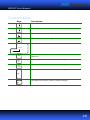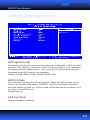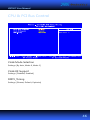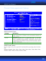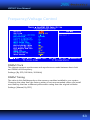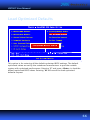
1
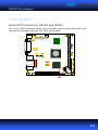
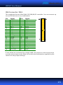
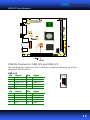
VB 7 0 0 7
Mini-ITX Mainboard Manual
JUNE 22, 2012
VERSION 1.06
Copyright and Trademarks
Copyright © 2012 VIA Technologies Incorporated. All rights reserved.
No part of this document may be reproduced, transmitted, transcribed, stored in a retrieval system, or translated into any
language, in any form or by any means, electronic, mechanical, magnetic, optical, chemical, manual or otherwise without
the prior written permission of VIA Technologies, Incorporated.
All trademarks are the property of their respective holders.
PS/2 is a registered trademark of IBM Corporation.
Disclaimer
No license is granted, implied or otherwise, under any patent or patent rights of VIA Technologies. VIA Technologies
makes no warranties, implied or otherwise, in regard to this document and to the products described in this document.
The information provided in this document is believed to be accurate and reliable as of the publication date of this
document. However, VIA Technologies assumes no responsibility for the use or misuse of the information in this
document and for any patent infringements that may arise from the use of this document. The information and product
specifications within this document are subject to change at any time, without notice and without obligation to notify any
person of such change.
Battery Recycling and Disposal
Only use the appropriate battery specified for this product.
Do not re-use, recharge, or reheat an old battery.
Do not attempt to force open the battery.
Do not discard used batteries with regular trash.
Discard used batteries according to local regulations.
II
Regulatory Compliance
FCC-B Radio Frequency Interference Statement
This equipment has been tested and found to comply with the limits for a class B digital device, pursuant to part 15 of the
FCC rules. These limits are designed to provide reasonable protection against harmful interference when the equipment is
operated in a commercial environment. This equipment generates, uses, and can radiate radio frequency energy and, if
not installed and used in accordance with the instruction manual, may cause harmful interference to radio
communications. Operation of this equipment in a residential area is likely to cause harmful interference, in which case the
user will be required to correct the interference at his personal expense.
Notice 1
The changes or modifications not expressly approved by the party responsible for compliance could void the user's
authority to operate the equipment.
Notice 2
Shielded interface cables and A.C. power cord, if any, must be used in order to comply with the emission limits.
Tested To Comply
With FCC Standards
FOR HOME OR OFFICE USE
KC Korean Certificate Statement
KCC-REM-VNT-VB7007 (B)
VIA Technologies, Inc.
VB7007
Global Brands MFR LTD PCBA Business Unit
2009/02
Made in China
B 급 기기
( 가정용 방송통신기자재 )
이 기기는 가정용 (B 급 ) 전자파적합기기로서 주
로 가정에서 사용하는 것을 목적으로 하며 , 모
든 지역에서 사용할 수 있습니다 .
Class B Equipment
(For Home Use
Broadcasting & Communication
Equipment)
This electromagnetic wave equipment is suitable for
home use (Class B) and may be used mainly at home
and in other areas.
III
Safety Precautions
Always read the safety instructions carefully.
Keep this User's Manual for future reference.
Keep this equipment away from humidity.
Lay this equipment on a reliable flat surface before setting it up.
The openings on the enclosure are for air convection hence
protects the equipment from overheating. Do not cover the
openings.
Make sure the voltage of the power source and adjust properly
110/220V before connecting the equipment to the power inlet.
Place the power cord in such a way that people cannot step on it.
Do not place anything over the power cord.
Always unplug the power cord before inserting any add-on card
or module.
All cautions and warnings on the equipment should be noted.
Never pour any liquid into the opening. Liquid can cause
damage or electrical shock.
If any of the following situations arises, get the equipment
checked by authorized service personnel:
o The power cord or plug is damaged.
o Liquid has penetrated into the equipment.
o The equipment has been exposed to moisture.
o The equipment has not worked well or you cannot get it
work according to User's Manual.
o The equipment has dropped and damaged.
o The equipment has obvious sign of breakage.
Do not leave this equipment in an environment unconditioned or
in a storage temperature above 60°C (140°F). The equipment
may be damaged.
IV
Box Contents
1 x VB7007 mainboard
1 x ATA-66/100/133 IDE ribbon cable
1 x I/O bracket
V
TABLE OF CONTENTS
1: Specifications................................................................................................................ 1
Mainboard Specifications.......................................................................................... 2
Mainboard Layout........................................................................................................ 5
Back Panel Layout ........................................................................................................ 6
2: Installation ..................................................................................................................... 7
CPU..................................................................................................................................... 8
CPU Fan and System Fan: CPUFAN and SYSFAN ........................................ 8
Memory Module Installation ................................................................................... 9
Memory Slot: DDR2 DIMM .................................................................................. 9
DDR2 SDRAM Module Installation Procedures .........................................10
Available DDR2 SDRAM Configurations.......................................................10
Connecting the Power Supply...............................................................................11
ATX 20-Pin Power Connector ...........................................................................12
Back Panel Ports..........................................................................................................13
PS/2 ports: mouse and keyboard ....................................................................13
VGA port....................................................................................................................13
Serial port: COM1 ..................................................................................................13
Parallel port ..............................................................................................................13
USB Ports...................................................................................................................13
LAN Ports ..................................................................................................................13
Audio jacks: Line-in, Line-out, and MIC-in...................................................13
Connectors ....................................................................................................................14
Serial ATA Connectors: SATA1 and SATA2 ..................................................14
IDE Connector: IDE1..............................................................................................15
USB Pin Connector: USB_0/1 and USB_2/3..................................................16
Digital I/O Connector: DIO.................................................................................17
System Management Bus Connector: SMBUS ...........................................18
Serial Port Connector: COM2/3/4 ...................................................................18
Case Connector: F_PANEL ..................................................................................19
KBMS Connector: KB/MS ....................................................................................20
Fast Infrared Connector: FIR ..............................................................................21
VI
S/PDIF Connector: SPDIF ....................................................................................21
Front Audio: F_AUDIO..........................................................................................22
LVDS Connector: PANEL_CONN ......................................................................23
LVDS Inverter: INVERTER ....................................................................................23
Jumpers ..........................................................................................................................24
Clear CMOS Connector: CLEAR_CMOS .........................................................24
Voltage Selector for COM2/3/4: J3/2/1 ........................................................24
Panel Power Selector: PVDD..............................................................................25
Inverter Power Selector: IVDD_SEL .................................................................25
Slots .................................................................................................................................26
Peripheral Component Interconnect: PCI_SLOT ........................................26
PCI Interrupt Request Routing .........................................................................26
3: BIOS Setup...................................................................................................................27
Entering the BIOS Setup Menu .............................................................................28
Control Keys .................................................................................................................29
Navigating the BIOS Menus...................................................................................31
Getting Help .................................................................................................................32
Main Menu....................................................................................................................33
Standard CMOS Features ...................................................................................33
Advanced BIOS Features.....................................................................................33
Advanced Chipset Features ...............................................................................33
Integrated Peripherals..........................................................................................33
Power Management Setup ................................................................................33
PnP/PCI Configurations.......................................................................................34
PC Health Status.....................................................................................................34
Frequency/Voltage Control ...............................................................................34
Load Optimized Defaults ....................................................................................34
Set Supervisor Password.....................................................................................34
Set User Password .................................................................................................34
Save & Exit Setup...................................................................................................34
Exit Without Saving...............................................................................................34
Standard CMOS Features ........................................................................................35
Date .............................................................................................................................35
Time.............................................................................................................................35
Halt On.......................................................................................................................35
VII
IDE Channels.................................................................................................................36
Advanced BIOS Features .........................................................................................37
Virus Warning..........................................................................................................37
CPU L1 & L2 Cache ...............................................................................................37
CPU L2 Cache ECC Checking.............................................................................38
Quick Power On Self-Test...................................................................................38
First/Second/Third Boot Device .......................................................................38
Boot Other Device .................................................................................................38
Boot Up NumLock Status ...................................................................................38
Typematic Rate Setting .......................................................................................38
Typematic Rate (Chars/Sec)...............................................................................39
Typematic Delay (Msec) ......................................................................................39
Security Option.......................................................................................................39
MPS Version Control for OS ..............................................................................39
Display Full Screen Logo.....................................................................................39
Summary Screen Show ........................................................................................39
CPU Feature ..................................................................................................................40
Thermal Management..........................................................................................40
Hard Disk Boot Priority.............................................................................................41
Advanced Chipset Features ....................................................................................42
Display Card Priority .............................................................................................42
Video RAM Cacheable .........................................................................................42
AGP Driving Control .............................................................................................42
AGP Driving Value .................................................................................................43
Select Display Device............................................................................................43
Panel Type ................................................................................................................43
AGP & P2P Bridge Control......................................................................................44
AGP Aperture Size .................................................................................................44
AGP3.0 Mode...........................................................................................................44
AGP Fast Write ........................................................................................................44
AGP 3.0 Calibration Cycle ...................................................................................45
VGA Share Memory Size .....................................................................................45
Direct Frame Buffer ...............................................................................................45
Outport Port.............................................................................................................45
Dithering....................................................................................................................45
VIII
CPU & PCI Bus Control.............................................................................................46
VLink Mode Selection ..........................................................................................46
VLink 8X Support ...................................................................................................46
DRDY_Timing...........................................................................................................46
Integrated Peripherals ..............................................................................................47
Onboard IDE Channel 1 and 2..........................................................................47
IDE Prefetch Mode ................................................................................................47
IDE HDD Block Mode ...........................................................................................47
SATA Controller ......................................................................................................48
SATA Controller Mode.........................................................................................48
Azalia HDA Controller ..........................................................................................48
LAN Controller ........................................................................................................48
OnChip LAN Boot ROM.......................................................................................48
Giga LAN Boot ROM.............................................................................................48
WatchDog Support ...............................................................................................49
Watch Dog Timer Select .....................................................................................49
Watch Dog Count Value .....................................................................................49
SuperIO Device............................................................................................................50
Onboard Serial Port 1/2/3/4..............................................................................50
Onboard Parallel Port...........................................................................................50
Parallel Port Mode.................................................................................................51
EPP Mode Select ....................................................................................................51
ECP Mode Use DMA .............................................................................................51
Onboard Fast IR......................................................................................................51
Fast IR IRQ ................................................................................................................51
Fast IR DMA..............................................................................................................51
VIA OnChip IDE Device.............................................................................................52
DOM support UDMA66.......................................................................................52
IDE DMA Transfer Access ...................................................................................52
USB Device Setting ....................................................................................................53
USB 1.0 Controller .................................................................................................53
USB 2.0 Controller .................................................................................................53
USB Operation Mode ...........................................................................................53
USB Keyboard Function.......................................................................................54
USB Mouse Function ............................................................................................54
IX
USB Storage Function ..........................................................................................54
Power Management Setup .....................................................................................55
ACPI Suspend Type ...............................................................................................55
HDD Power Down..................................................................................................55
Power Management Timer.................................................................................56
Video Off Option....................................................................................................56
Power Off by PWRBTN.........................................................................................56
Run VGABIOS if S3 Resume...............................................................................56
AC Loss Auto Restart ............................................................................................56
Peripherals Activities .................................................................................................57
PS2KB Wakeup Select ..........................................................................................57
PS2KB Wakeup Key Select..................................................................................57
PS2MS Wakeup Key Select ................................................................................57
PS2 Keyboard Power ON ....................................................................................57
PS2 Mouse Power ON..........................................................................................58
USB Resume.............................................................................................................58
PowerOn by PCI Card...........................................................................................58
RTC Alarm Resume................................................................................................58
Date (of Month)......................................................................................................58
Resume Time (hh:mm:ss) ....................................................................................58
PnP/PCI Configurations............................................................................................59
PNP OS Installed ....................................................................................................59
Reset Configuration Data ...................................................................................60
Resources Controlled By .....................................................................................60
Assign IRQ for VGA ...............................................................................................60
Assign IRQ for USB................................................................................................60
IRQ Resources..............................................................................................................61
PC Health Status .........................................................................................................62
Frequency/Voltage Control ....................................................................................63
DRAM Clock .............................................................................................................63
DRAM Timing ..........................................................................................................63
SDRAM CAS Latency.............................................................................................64
Bank Interleave .......................................................................................................64
Precharge to Active (Trp) ....................................................................................64
Active to Precharge (Tras) ..................................................................................64
X
Active to CMD (Trcd) ............................................................................................64
REF to ACT/REF (Trfc) ...........................................................................................65
ACT(0) to ACT(1) (TRRD) .....................................................................................65
Read to Precharge (Trtp).....................................................................................65
Write to Read CMD (Twtr)..................................................................................65
Write Recovery Time (Twr) .................................................................................65
RSAIT Mode .............................................................................................................65
RSAIT Selection.......................................................................................................65
Auto Detect PCI Clk...............................................................................................65
Spread Spectrum ...................................................................................................65
Load Optimized Defaults.........................................................................................66
Set Supervisor/User Password...............................................................................67
Save & Exit Setup .......................................................................................................69
Exit Without Saving....................................................................................................70
4: Driver Installation ......................................................................................................71
Microsoft Driver Support.........................................................................................72
Linux Driver Support .................................................................................................73
XI
VB7007 User Manual
1:
Specifications
The compact and highly integrated VIA VB7007 mainboard comes with an
®
integrated VIA C7 NanoBGA2 processor, boasting of ultra-low power
consumption and cool operation.
1
VB7007 User Manual
Mainboard Specifications
CPU
•
VIA C7 -D 1.6 GHz NanoBGA2 processor with fansink
•
VIA C7 1.0 GHz NanoBGA2 processor (fanless)
®
®
Chipset
•
VIA CN700 North Bridge
•
VIA VT8237S South Bridge
Graphics
•
Integrated VIA UniChrome™ Pro II AGP graphics with 2D/3D and video
acceleration
Memory
•
1
One DDR2 667 /533 DIMM slots (up to 1 GB)
Expansion Slot
•
One PCI slot
•
One UltraDMA 133/100/66/33 connector
IDE
LAN
•
One VIA VT6103L 10/100 Mbps Fast Ethernet PHY
•
One VIA VT6107 10/100 Mbps Fast Ethernet controller or
2
one VIA VT6122 Gigabit LAN controller
Audio Codec
•
1
2
VIA VT1708B High Definition audio codec
DDR2 667 MHz memory modules can be used but the effective speed with be limited to 533 MHz.
The VT6122 Gigabit LAN controller is a manufacturing option.
2
VB7007 User Manual
Back Panel I/O Ports
•
One VGA port
•
One COM port
•
One parallel port
•
Two RJ-45 LAN ports
•
Four USB 2.0 ports
•
Three audio jacks: Line-in, Line-out, and MIC-in
•
Two PS/2 ports: mouse and keyboard
Onboard I/O Connectors
•
Three COM pin headers (with 5V/12V select)
•
One digital I/O pin header (GPI x 4, GPO x 4)
•
Two USB 2.0 pin headers (up to four additional ports)
•
Two SATA connectors
•
One SMBus pin header
•
One S/PDIF-out connector
•
One dual-channel LVDS panel connector (18/24-bit)
•
One LVDS panel power selector (5V/3.3V)
•
One LVDS inverter pin header
•
One LVDS inverter power selector (5V/12V)
•
One FIR pin header
•
One chassis front panel pin header
•
One front audio pin header
•
Two fan connectors (CPU and SYS)
•
One ATX power connector
3
VB7007 User Manual
System Monitoring and Management
•
AC power failure recovery
•
RTC timer
•
Wake-on LAN, keyboard, and mouse
Supported OS
•
Windows 2000
•
Windows XP
•
Windows CE
•
Windows XPe
•
Linux
BIOS
•
Award BIOS
•
SPI 4/8Mbit flash memory
Operating Environment
•
Temperature range: 0°C - 50°C
•
Humidity range: 0% - 95%
3
Form Factor
•
3
Mini-ITX (17 cm x 17 cm)
Relative humidity and non-condensing.
4
VB7007 User Manual
Mainboard Layout
ATX Power
KB/MS
VIA C7 processor
CPU_Fan
SYS_Fan
J2
DDR2 Memory slot
J1
CN700 North Bridge
FIR
Buzzer
COM3
SMBus
COM4
J3
COM2
DIO
Inverter
PVDD
IVDD_SEL
VT8237S South Bridge
IDE
1
Battery
Front Panel
Front Audio
SPDIF
USB_0/1
LVDS Panel
PCI
SATA
Clear CMOS
USB_2/3
5
VB7007 User Manual
Back Panel Layout
6
VB7007 User Manual
2:
Installation
This chapter provides you with information about hardware installation
procedures. It is recommended to use a grounded wrist strap before handling
computer components. Electrostatic discharge (ESD) can damage some
components.
7
VB7007 User Manual
CPU
®
The VIA VB7007 mainboard is packaged with either the VIA C7 -D 1.6 GHz or VIA
®
®
C7 1.0 GHz NanoBGA2 processor. The VIA C7 -D 1.6 GHz processor requires a
®
heatsink with fan to provide sufficient cooling. The VIA C7 1.0 GHz processor is
for fanless solutions.
VIA C7 processor
SYS_Fan
CPU_Fan
1
CPU Fan and System Fan: CPUFAN and SYSFAN
The CPU_FAN (CPU fan) and SYS_FAN (system fan) run on +12V and maintain
system cooling. When connecting the wire to the connectors, always be aware
that the red wire (positive wire) should be connected to the +12V. The black wire
is Ground and should always be connected to GND.
Pin
Signal
1
2
3
FANIO
+12V
GND
8
VB7007 User Manual
Memory Module Installation
Memory Slot: DDR2 DIMM
The VIA VB7007 mainboard has one 240-DIMM slot for DDR2 667/533 SDRAM
4
memory modules and supports memory sizes up to 1 GB.
4
1 GB SDRAM only supported with 64 MB x 8-bit x 16 configuration.
9
VB7007 User Manual
DDR2 SDRAM Module Installation Procedures
•
Locate the DIMM slot in the motherboard.
•
Unlock a DIMM slot by pressing the retaining clips outward.
•
Align a DIMM on the socket such that the notch on the DIMM matches
the break on the slot.
•
Firmly insert the DIMM into the slot until the retaining clips snap back in
place and the DIMM is properly seated.
Available DDR2 SDRAM Configurations
Refer to the table below for available DDR2 SDRAM configurations on the
mainboard.
Slot
Module Size
DIMM1
64 MB, 128 MB, 256 MB, 512 MB, 1 GB
Maximum supported system memory
Total
64 MB - 1 GB
64 MB - 1 GB
10
VB7007 User Manual
Connecting the Power Supply
The VIA VB7007 mainboard supports a conventional ATX power supply for the
power system. Before inserting the power supply connector, always make sure
that all components are installed correctly to ensure that no damage will be
caused.
11
VB7007 User Manual
ATX 20-Pin Power Connector
To connect the power supply, make sure the power plug is inserted in the proper
orientation and the pins are aligned. Then push down the plug firmly into the
connector.
Pin
Signal
Pin
Signal
1
2
3
4
5
6
7
8
9
10
+3.3V
+3.3V
GND
+5V
GND
+5V
GND
Power Good
+5V Standby
+12V
11
12
13
14
15
16
17
18
19
20
+3.3V
-12V
GND
Power Supply On
GND
GND
GND
-5V
+5V
+5V
12
VB7007 User Manual
Back Panel Ports
The back panel has the following ports:
PS/2 ports: mouse and keyboard
The green PS/2 port is used to connect a mouse. The purple PS/2 port is used to
connect a keyboard.
VGA port
The 15-pin VGA port is for connecting to analog displays.
Serial port: COM1
The 9-pin COM port is for pointing devices or other serial devices.
Parallel port
The parallel port is for connecting to LPT devices.
USB Ports
Four standard USB 2.0 ports are provided on the back panel.
LAN Ports
The mainboard provides two Fast Ethernet ports controlled with separate VIA
Fast Ethernet controllers. One of the controllers can be substituted for a Gigabit
LAN controller as a manufacturing option.
Audio jacks: Line-in, Line-out, and MIC-in
Three audio jacks are provided on the back panel.
13
VB7007 User Manual
Connectors
Serial ATA Connectors: SATA1 and SATA2
The current SATA interface allows up to 300 MB/s data transfer rate, faster than
the standard parallel ATA with 133 MB/s (Ultra DMA).
14
VB7007 User Manual
IDE Connector: IDE1
The mainboard has an Ultra DMA 133/100/66/33 controller. You can connect up
to two IDE devices in any combination.
Pin
Signal
Pin
Signal
1
3
5
7
9
11
13
15
17
19
21
23
25
27
29
31
33
35
37
39
-IDERST1
PD_7
PD_6
PD_5
PD_4
PD_3
PD_2
PD_1
PD_0
GND
PDREQ
-PIOW
-PIOR
PDRDY
-PDACK
IRQ14_R
PD_A1
PD_A0
-PCS_1
-HD_LED1
2
4
6
8
10
12
14
16
18
20
22
24
26
28
30
32
34
36
38
40
GND
PD_8
PD_9
PD_10
PD_11
PD_12
PD_13
PD_14
PD_15
KEY
GND
GND
GND
GND
GND
NC
P_ATA66
PD_A2
-PCS_3
GND
If two drives are connected to a single cable, the jumper on the second drive
must be set to slave mode. Refer to the drive documentation supplied by the
vendor for the jumper settings.
15
VB7007 User Manual
USB Pin Connector: USB_0/1 and USB_2/3
The mainboard provides two 10-pin USB pin connectors (allowing up to four
additional USB 2.0 ports).
USB_0/1
Pin
Signal
Pin
Signal
1
3
5
7
9
VUSB0
USBD_T0USBD_T0+
GND
KEY
2
4
6
8
10
VUSB0
USBD_T1USBD_T1+
GND
GND
USB_2/3
Pin
Signal
Pin
Signal
1
3
5
7
9
VUSB0
USBD_T2USBD_T2+
GND
KEY
2
4
6
8
10
VUSB0
USBD_T3USBD_T3+
GND
GND
16
VB7007 User Manual
Digital I/O Connector: DIO
General purpose digital input and output.
Pin
Signal
Pin
Signal
1
3
5
7
9
11
+5V
GPO1
GPO7
GPO26
GPO27
GND
2
4
6
8
10
12
+12V
GPI4
GPI13
GPI14
GPI15
GND
17
VB7007 User Manual
System Management Bus Connector: SMBUS
This pin header allows you to connect SMBus (System Management Bus) devices.
Devices communicate with a SMBus host and/or other SMBus devices using the
SMBus interface.
Pin
Signal
1
2
3
SMBCK
SMBDT
GND
Serial Port Connector: COM2/3/4
COM pin headers can be used to attach an additional port for serial devices.
Pin
Signal
Pin
Signal
1
3
5
7
9
COM_DCD
COM_SOUT
GND
COM_RTS
COM_RI
2
4
6
8
10
COM_SIN
COM_DTR
COM_DSR
COM_CTS
KEY
18
VB7007 User Manual
Case Connector: F_PANEL
The F_PANEL pin header allows you to connect the power switch, reset switch,
power LED, sleep LED, HDD LED and the case speaker.
Pin
Signal
Pin
Signal
1
3
5
7
9
11
13
15
+5VDUAL
+5VDUAL
-PLED_2
+5V
NC
NC
SPEAK
KEY
2
4
6
8
10
12
14
16
+5V
HD_LED
PW_BN
GND
RST_SW
GND
+5V
-SLEEP_LED
Power LED (PLED)
The LED will light when the system is on. If the system is in S1 (POS - Power On
Suspend) or S3 (STR - Suspend To RAM) state, the LED will blink.
HDD LED (HD_LED)
HDD LED shows the activity of a hard disk drive. Avoid turning the power off
when the HDD LED is still on. Connect the HDD LED from the system case to this
pin.
Power Switch (PW_BN)
Connect to a 2-pin power button switch. Pressing this button will turn the system
power on or off.
Speaker (SPEAK)
This pin header is for connecting to the system buzzer.
Reset Switch (RST_SW)
The reset switch is used to reboot the system rather than turning the power
ON/OFF. Avoid rebooting the system, if the HDD is still working. Connect the
reset switch from the system case to this pin.
Sleep LED (SLEEP_LED)
The SLEEP LED is lit when the system is in the S1 (POW-Power On Suspend)
19
VB7007 User Manual
KBMS Connector: KB/MS
The mainboard provides a PS2 pin header to attach a PS2 keyboard and mouse.
Pin
Signal
Pin
Signal
1
3
5
7
9
+5VDUAL
KB_CLK
EKBCLK
MS_CLK
EMSCLK
2
4
6
8
10
GND
KB_DATA
EKBDATA
MS_DATA
EMSDATA
20
VB7007 User Manual
Fast Infrared Connector: FIR
Pin
Signal
1
2
3
4
5
+5V
IRRX1
IRRX
GND
IRTX
S/PDIF Connector: SPDIF
Pin
Signal
1
3
5
+5V
SPDIF_OUT
GND
21
VB7007 User Manual
Front Audio: F_AUDIO
This connector allows you to connect a front audio panel to the mainboard.
Pin
Signal
Pin
Signal
1
3
5
7
9
MIC2_IN_L
MIC2_IN_R
HP_OUT_R
NC
HP_OUT_L
2
4
6
8
10
AGND
+3.3V
NC
KEY
NC
22
VB7007 User Manual
LVDS Connector: PANEL_CONN
Pin
Signal
Pin
Signal
1
3
5
7
9
11
13
15
17
19
21
23
25
27
29
31
33
35
37
39
-A4_L
A4_L
GND
-A5_L
A5_L
GND
-A6_L
A6_L
GND
-CLK2_L
CLK2_L
GND
-A7_L
A7_L
NC
NC
NC
NC
NC
NC
2
4
6
8
10
12
14
16
18
20
22
24
26
28
30
32
34
36
38
40
PVDD
PVDD
GND
GND
-A0_L
A0_L
GND
-A1_L
A1_L
GND
-A2_L
A2_L
GND
-CLK1_L
CLK1_L
GND
-A3_L
A3_L
SPCLK1
SPD1
LVDS Inverter: INVERTER
Pin
Signal
1
2
3
4
5
6
7
8
VCC
VCC
BAKLITE
NC
BAKLITE
SMBUS OUT
GND
GND
23
VB7007 User Manual
Jumpers
The mainboard provides jumpers for setting some mainboard functions. This
section will explain how to change the settings of the mainboard functions using
the jumpers.
Clear CMOS Connector: CLEAR_CMOS
The onboard CMOS RAM stores system configuration data and has an onboard
battery power supply. To reset the CMOS settings, set the jumper on pins 1 and 2
while the system is off. Return the jumper to pins 2 and 3 afterwards. Setting the
jumper while the system is on will damage the mainboard.
Setting
1
2
3
Normal Operation
Clear CMOS setting
ON
OFF
ON
ON
OFF
ON
Caution:
Except when clearing the RTC RAM, never remove the cap on CLEAR_CMOS
jumper default position. Removing the cap will cause system boot failure.
Avoid clearing the CMOS while the system is on; it will damage the
mainboard.
Voltage Selector for COM2/3/4: J3/2/1
This VCC selector is to determine the input voltage of each COM connector.
Setting
1
2
3
+5V
+12V
ON
OFF
ON
ON
OFF
ON
24
VB7007 User Manual
Panel Power Selector: PVDD
Setting
1
2
3
5V
3.3V
ON
OFF
ON
ON
OFF
ON
Inverter Power Selector: IVDD_SEL
Setting
1
2
3
5V
12V
ON
OFF
ON
ON
OFF
ON
25
VB7007 User Manual
Slots
Peripheral Component Interconnect: PCI_SLOT
The PCI slot allows you to insert a PCI expansion card. First unplug the power
supply before adding or removing expansion cards. Read the documentation for
the expansion card to see if any changes to the system are necessary.
PCI Interrupt Request Routing
The IRQ (interrupt request line) are hardware lines over which devices can send
interrupt signals to the microprocessor. The “PCI & LAN” IRQ pins are typically
connected to the PCI bus –INT_A ~ -INT_D pins as follows:
PCI slot
Order 1
Order 2
Order 3
Order 4
-INT_B
-INT_C
-INT_D
-INT_A
26
VB7007 User Manual
3:
BIOS Setup
This chapter gives a detailed explanation of the BIOS setup functions.
27
VB7007 User Manual
Entering the BIOS Setup Menu
Power on the computer and press <Delete> during the beginning of the boot
sequence to enter the BIOS setup menu. If you missed the BIOS setup entry point,
restart the system and try again.
28
VB7007 User Manual
Control Keys
Keys
Description
Move to the previous item
Move to the next item
Move to the item in the left side
Move to the item in the right side
Select the item
Enter
Esc
Page
Up
Page
Down
Jumps to the Exit menu or returns to the main menu from a
submenu
Increase the numeric value or make changes
Decrease the numeric value or make changes
Increase the numeric value or make changes
Decrease the numeric value or make changes
29
VB7007 User Manual
Keys
Description
F1
General help, only for Status Page Setup Menu and Option
Page Setup Menu
F5
Restore the previous CMOS value from CMOS, only for
Option Page Setup Menu
F6
Load the default CMOS value from Fail-Safe default table,
only for Option Page Setup Menu
F7
F10
Load Optimized defaults
Save all the CMOS changes and exit
30
VB7007 User Manual
Navigating the BIOS Menus
The main menu displays all the BIOS setup categories. Use the <Left>/<Right>
and <Up>/<Down> arrow keys to select any item or sub-menu. Descriptions of
the selected/highlighted category are displayed at the bottom of the screen.
The small triangular arrowhead symbol next to a field indicates that a sub-menu
is available (see figure below). Press <Enter> to display the sub-menu. To exit the
sub-menu, press <Esc>.
31
VB7007 User Manual
Getting Help
The BIOS setup program provides a “General Help” screen. You can display this
screen from any menu/sub-menu by pressing <F1>. The help screen displays the
keys for using and navigating the BIOS setup. Press <Esc> to exit the help screen.
32
VB7007 User Manual
Main Menu
The Main Menu contains thirteen setup functions and two exit choices. Use arrow
keys to select the items and press <Enter> to accept or enter Sub-menu.
Standard CMOS Features
Use this menu to set basic system configurations.
Advanced BIOS Features
Use this menu to set the advanced features available on your system.
Advanced Chipset Features
Use this menu to set chipset specific features and optimize system performance.
Integrated Peripherals
Use this menu to set onboard peripherals features.
Power Management Setup
Use this menu to set onboard power management functions.
33
VB7007 User Manual
PnP/PCI Configurations
Use this menu to set the PnP and PCI configurations.
PC Health Status
This menu shows the PC health status.
Frequency/Voltage Control
Use this menu to set the system frequency and voltage control.
Load Optimized Defaults
Use this menu option to load BIOS default settings for optimal and high
performance system operations.
Set Supervisor Password
Use this menu option to set the BIOS supervisor password.
Set User Password
Use this menu option to set the BIOS user password.
Save & Exit Setup
Save BIOS setting changes and exit setup.
Exit Without Saving
Discard all BIOS setting changes and exit setup.
34
VB7007 User Manual
Standard CMOS Features
Date
The date format is [Day, Month Date, Year]
Time
The time format is [Hour : Minute : Second]
Halt On
Set the system’s response to specific boot errors. Below is a table that details the
possible settings.
Settings
Description
All Errors
No Errors
All, But Keyboard
System halts when any error is detected
System does not halt for any error
System halts for all non-key errors
35
VB7007 User Manual
IDE Channels
The specifications of your drive must match with the drive table. The hard disk
will not work properly if you enter incorrect information in this category. Select
“Auto” whenever possible. If you select “Manual”, make sure the information is
from your hard disk vendor or system manufacturer.
Below is a table that details required hard drive information when using the
“Manual” mode.
Settings
Description
IDE Channel
The name of this match the name of the menu. Settings:
[None, Auto, Manual]
Settings: [CHS, LBA, Large, Auto]
Formatted size of the storage device
Number of cylinders
Number of heads
Write precompensation
Cylinder location of the landing zone
Number of sectors
Settings: [ Auto, Mode 1, Mode 2, Mode 3, Mode 4]
Settings: [Disabled, Auto]
Access Mode
Capacity
Cylinder
Head
Precomp
Landing Zone
Sector
Primary PIO
Primary UDMA
36
VB7007 User Manual
Advanced BIOS Features
Virus Warning
Allows you to choose the VIRUS warning feature for IDE Hard Disk boot sector
protection.
Settings
Description
Enabled
Disabled
Turns on hard disk boot sector virus protection
Turns off hard disk boot sector virus protection
Note:
If this function is enabled and someone attempt to write data into this area,
BIOS will show a warning message on the screen and alarm beep.
CPU L1 & L2 Cache
Settings: [Disabled, Enabled]
37
VB7007 User Manual
CPU L2 Cache ECC Checking
This feature facilitates error detection/correction when data passes through Level
2 cache.
Settings: [Disabled, Enabled]
Quick Power On Self-Test
Shortens Power On Self-Test (POST) cycle to enable shorter boot up time.
Settings
Description
Disabled
Enabled
Standard Power On Self Test (POST)
Shorten Power On Self Test (POST) cycle and boot up time
First/Second/Third Boot Device
Set the boot device sequence as BIOS attempts to load the disk operating system.
Settings
Description
Removable
Hard Disk
CDROM
USB-CDROM
Network
Disabled
Boot from external drive
Boot from the HDD
Boot from CDROM
Boot from USB CDROM
Boot from network drive
Disable the boot device sequence
Boot Other Device
Enables the system to boot from alternate devices if the system fails to boot from
the “First/Second/Third Boot Device” lists.
Settings
Description
Disabled
Enabled
No alternate boot device allowed
Enable alternate boot device
Boot Up NumLock Status
Set the NumLock status when the system is powered on.
Settings
Description
Off
On
Forces keypad to behave as arrow keys
Forces keypad to behave as 10-key
Typematic Rate Setting
Enable “Typematic Rate” function.
Settings: [Disabled, Enabled]
38
VB7007 User Manual
Typematic Rate (Chars/Sec)
This item sets the rate (characters/second) at which the system retrieves a signal
from a depressed key.
Settings: [6, 8, 10, 12, 15, 20, 24, 30]
Typematic Delay (Msec)
This item sets the delay between, when the key was first pressed and when the
system begins to repeat the signal from the depressed key.
Settings: [250, 500, 750, 1000]
Security Option
Selects whether the password is required every time the System boots, or only
when you enter Setup.
Settings
Description
Setup
Password prompt appears only when end users try to run BIOS
Setup
Password prompt appears every time when the computer is
powered on and when end users try to run BIOS Setup
System
MPS Version Control for OS
Settings: [1.1, 1.4]
Display Full Screen Logo
Show full screen logo during BIOS boot up process.
Settings: [Disabled, Enabled]
Summary Screen Show
Show summary screen.
Settings: [Disabled, Enabled]
39
VB7007 User Manual
CPU Feature
Thermal Management
This item sets CPU’s thermal control rule to protect CPU from overheat.
Settings
Description
Thermal Monitor 1
On-die throttling
40
VB7007 User Manual
Hard Disk Boot Priority
This is for setting the priority of the hard disk boot order when the “Hard Disk”
option is selected in the “[First/Second/Third] Boot Device” menu item.
41
VB7007 User Manual
Advanced Chipset Features
Caution:
The Advanced Chipset Features menu is used for optimizing the chipset
functions. Do not change these settings unless you are familiar with the
chipset.
Display Card Priority
Settings: [PCI Slot, AGP]
Video RAM Cacheable
Settings: [Disabled, Enabled]
AGP Driving Control
Settings: [Auto, Manual]
42
VB7007 User Manual
AGP Driving Value
This option can only be altered if “AGP Driving Control” is set to “Manual”. Input
is expected as hexidecimal
Select Display Device
Settings: [CRT, LCD, CRT&LCD]
Panel Type
Settings
00
01
02
03
04
Description
640 x 480
800 x 600
1024 x 768
1280 x 768
1280 x 1024
43
VB7007 User Manual
AGP & P2P Bridge Control
AGP Aperture Size
This setting controls how much memory space can be allocated to AGP for video
purposes. The aperture is a portion of the PCI memory address range dedicated
to graphics memory address space. Host cycles that hit the aperture range are
forwarded to the AGP without any translation.
Settings: [32MB, 64MB, 128MB, 256MB, 512MB, 1GB]
AGP3.0 Mode
This mainboard supports the AGP 8x interface. When the AGP 8x video card is
used, it can transfer video data at 2133MB/s. AGP 8x is backward compatible,
leave the default 4x mode on. AGP 4x mode can be detected automatically once
you plug in the AGP 4x card.
Settings: [8x, 4x]
AGP Fast Write
Settings: [Disabled, Enabled]
44
VB7007 User Manual
AGP 3.0 Calibration Cycle
Settings: [Disabled, Enabled]
VGA Share Memory Size
This setting allows you to select the amount of system memory that is allocated
to the integrated graphics processor.
Settings: [Disabled, 16M, 32M, 64M]
Direct Frame Buffer
Settings: [Disabled, Enabled]
Outport Port
Settings: [DI0, DI1]
Dithering
Settings: [Disabled, Enabled]
45
VB7007 User Manual
CPU & PCI Bus Control
VLink Mode Selection
Settings: [By Auto, Mode 0, Mode 1]
VLink 8X Support
Settings: [Disabled, Enabled]
DRDY_Timing
Settings: [Slowest, Default, Optimize]
46
VB7007 User Manual
Integrated Peripherals
Onboard IDE Channel 1 and 2
The integrated peripheral controller contains an IDE interface with support for
two IDE channels.
Settings: [Disabled, Enabled]
IDE Prefetch Mode
This allows your hard disk controller to use the fast block mode to transfer data
to and from the hard disk drive. Block mode is also called block transfer, multiple
commands or multiple sector read/write.
Settings: [Disabled, Enabled]
IDE HDD Block Mode
Automatic detection of the optimal number of block read/writes per sector the
drive can support.
Settings: [Disabled, Enabled]
47
VB7007 User Manual
SATA Controller
Settings: [Disabled, Enabled]
SATA Controller Mode
Controls the features of the Serial ATA controller within the South Bridge. Serial
ATA is the latest generation of the ATA interface. Serial ATA hard drives deliver
transfer speeds of up to 300MB/sec.
Settings
Description
IDE
RAID
AHCI
Supports two PATA hard disk drives. Disables RAID and AHCI
function.
Only SATA supports RAID and AHCI function
Enable the AHCI function such as Native Command Queuing and
Hot Plug function
Azalia HDA Controller
Settings: [Auto, Disabled]
LAN Controller
Settings: [Enabled, Disabled]
OnChip LAN Boot ROM
Decide whether to invoke the boot ROM of the onboard LAN chip.
Settings: [Enabled, Disabled]
Giga LAN Boot ROM
Decide whether to invoke the boot ROM of the onboard GigaLAN chip.
Settings: [Enabled, Disabled]
48
VB7007 User Manual
WatchDog Support
Settings: [Enabled, Disabled]
Watch Dog Timer Select
This option can only be altered if “WatchDog Support” is enabled.
Settings: [Minute, Second]
Watch Dog Count Value
This option can only be altered if “WatchDog Support” is enabled.
Settings: [any integer from 0 to 255]
49
VB7007 User Manual
SuperIO Device
Onboard Serial Port 1/2/3/4
Set the base I/O port address and IRQ for the onboard serial port A / serial port B.
Selecting Auto allows BIOS to automatically determine the correct base I/O port
address. Settings:
Port
1
2
3
4
Settings
Disabled
Disabled
Disabled
Disabled
3F8/IRQ4
3F8/IRQ4
3F8/IRQ5
3F8/IRQ5
2F8/IRQ3
2F8/IRQ3
2F8/IRQ10
2F8/IRQ10
3E8/IRQ4
3E8/IRQ4
3E8/IRQ5
3E8/IRQ5
2E8/IRQ3
2E8/IRQ3
2E8/IRQ10
2E8/IRQ10
Auto
Auto
-----
Onboard Parallel Port
This specifies the I/O port address and IRQ of the onboard parallel port.
Settings: [Disabled, 378/IRQ7, 278/IRQ5, 3BC/IRQ7]
50
VB7007 User Manual
Parallel Port Mode
Set the parallel port mode. To operate the onboard parallel port as Standard
Parallel Port, choose SPP. To operate the onboard parallel port in the EPP mode,
choose EPP. By choosing ECP, the onboard parallel port will operate in ECP mode.
Choosing ECP + EPP will allow the onboard parallel port to support both the ECP
and EPP modes simultaneously.
Settings: [SPP, EPP, ECP, ECP + EPP]
EPP Mode Select
EPP (Enhanced Parallel Port) comes in two modes: 1.9 and 1.7. EPP 1.9 is the
newer version of the protocol and is backwards compatible with most EPP
devices. If your EPP device does not work with the EPP 1.9 setting, try changing
the setting to EPP 1.7.
Settings: [EPP 1.9, EPP 1.7]
ECP Mode Use DMA
ECP (Extended Capabilities Port) has two DMA channels that it can use. The
default channel is 3. However, some expansion cards may use channel 3 as well.
To solve this conflict, change the ECP channel to 1. Select a DMA channel for the
port.
Settings: [1, 3]
Onboard Fast IR
Enables or disables the infrared port.
Settings: [Enabled and Disabled]
Fast IR IRQ
Set this field to reserve an IRQ for the Fast IR port. This field is only available if
Onboard Fast IR is enabled.
Settings: [3, 4]
Fast IR DMA
Set this field to choose the DMA channel. This field is only available if Onboard
Fast IR is enabled.
Settings: [6, 5]
51
VB7007 User Manual
VIA OnChip IDE Device
DOM support UDMA66
Settings: [Disabled, Enabled]
IDE DMA Transfer Access
Settings: [Disabled, Enabled]
52
VB7007 User Manual
USB Device Setting
USB 1.0 Controller
Enable or disable Universal Host Controller Interface for Universal Serial Bus.
Settings: [Disabled, Enabled]
USB 2.0 Controller
Enable or disable Enhanced Host Controller Interface for Universal Serial Bus.
Settings: [Disabled, Enabled]
USB Operation Mode
Auto decide USB device operation mode.
Settings
Description
Full/Low Speed
High Speed
All of USB Device operated on full/low speed mode
If USB device was high speed device, then it operated on high
speed mode.
53
VB7007 User Manual
USB Keyboard Function
Enable or disable Legacy support of USB Keyboard.
Settings: [Disabled, Enabled]
USB Mouse Function
Enable or disable Legacy support of USB Mouse.
Settings: [Disabled, Enabled]
USB Storage Function
Enable or disable Legacy support of USB Mass Storage.
Settings: [Disabled, Enabled]
54
VB7007 User Manual
Power Management Setup
ACPI Suspend Type
Settings
Description
S1(POS)
S1/Power On Suspend (POS) is a low power state. In this state, no
system context (CPU or chipset) is lost and hardware maintains all
system contexts.
S3/Suspend To RAM (STR) is a power-down state. In this state,
power is supplied only to essential components such as main
memory and wakeup-capable devices. The system context is saved
to main memory, and context is restored from the memory when a
"wakeup" event occurs.
Depends on the OS to select S1 or S3.
S3(STR)
S1 & S3
HDD Power Down
Set the length of time for a period of inactivity before powering down the hard
disk.
Settings: [Disable, 1 Min, 2 Min, 3 Min, 4 Min, 5 Min, 6 Min, 7 Min, 8 Min, 9 Min,
10 Min, 11 Min, 12 Min, 13 Min, 14 Min, 15 Min]
55
VB7007 User Manual
Power Management Timer
Settings: [Disable, 1 Min, 2 Min, 4 Min, 6 Min, 8 Min, 10 Min, 20 Min, 30 Min, 40
Min, 1 Hour]
Video Off Option
Select whether or not to turn off the screen when system enters power saving
mode, ACPI OS such as Windows XP will override this option.
Settings
Description
Always On
Suspend -> Off
Screen is always on even when system enters power saving mode
Screen is turned off when system enters power saving mode
Power Off by PWRBTN
Settings
Description
Delay 4 Sec
System is turned off if power button is pressed for more than four
seconds.
Power button functions as a normal power-on/-off button.
Instant-Off
Run VGABIOS if S3 Resume
Select whether to run VGA BIOS if resuming from S3 state. This is only necessary
for older VGA drivers.
Settings: [Auto, Yes, No]
AC Loss Auto Restart
The field defines how the system will respond after an AC power loss during system
operation.
Settings
Description
Off
On
Former-Sts
Keeps the system in an off state until the power button is pressed
Restarts the system when the power is back
Former-Sts
56
VB7007 User Manual
Peripherals Activities
PS2KB Wakeup Select
This feature has two settings: Hot Key and Password. To select the Password
option, press <Page Up> or <Page Down>. To set the password, enter up to
eight digits and press <Enter>.
Settings: [Hot Key, Password]
PS2KB Wakeup Key Select
This feature is only available when “Hot Key” is chosen in “PS2KB Wakeup Select”.
Settings: [Ctrl+F1, Ctrl+F2, Ctrl+F3, Ctrl+F4, Ctrl+F5, Ctrl+F6, Ctrl+F7, Ctrl+F8,
Ctrl+F9, Ctrl+F10, Ctrl+F11, Ctrl+F12, Power, Wake, Any Key]
PS2MS Wakeup Key Select
Settings: [Any Button, Left Button, Right Button]
PS2 Keyboard Power ON
Settings: [Disabled, Enabled]
57
VB7007 User Manual
PS2 Mouse Power ON
Settings: [Disabled, Enabled]
USB Resume
Settings: [Disabled, Enabled]
PowerOn by PCI Card
Enables activity detected from any PCI card to power up the system or resume from
a suspended state. Such PCI cards include LAN, onboard USB ports, etc.
Settings: [By OS, Enabled]
RTC Alarm Resume
Set a scheduled time and/or date to automatically power on the system.
Settings: [Disabled, Enabled]
Date (of Month)
This field can only be set if “RTC Alarm Resume” is enabled. The field specifies the
date for “RTC Alarm Resume”.
Resume Time (hh:mm:ss)
This field can only be set if “RTC Alarm Resume” is enabled. The field specifies the
time for “RTC Alarm Resume”.
58
VB7007 User Manual
PnP/PCI Configurations
Note:
This section covers some very technical items and it is strongly recommended
to leave the default settings as is unless you are an experienced user.
PNP OS Installed
Settings
Description
No
Yes
BIOS will initialize all the PnP cards
BIOS will only initialize the PnP cards used for booting (VGA,
IDE, SCSI). The rest of the cards will be initialized by the PnP
operating system
59
VB7007 User Manual
Reset Configuration Data
Settings
Description
Disabled
Enabled
Default setting
Resets the ESCD (Extended System Configuration Data) after
exiting BIOS Setup if a newly installed PCI card or the system
configuration prevents the operating system from loading
Resources Controlled By
Enables the BIOS to automatically configure all the Plug-and-Play compatible
devices.
Settings
Description
Auto(ESCD)
BIOS will automatically assign IRQ, DMA and memory base
address fields
Unlocks “IRQ Resources” for manual configuration
Manual
Assign IRQ for VGA
Assign IRQ for VGA devices.
Settings: [Disabled, Enabled]
Assign IRQ for USB
Assign IRQ for USB devices.
Settings: [Disabled, Enabled]
60
VB7007 User Manual
IRQ Resources
IRQ Resources list IRQ 7/9/10/11/12/14/15 for users to set each IRQ a type
depending on the type of device using the IRQ. Settings:
PCI Device
For Plug-and-Play compatible devices designed for PCI bus
architecture
Reserved
The IRQ will be reserved for further requests
61
VB7007 User Manual
PC Health Status
The PC Health Status displays the current status of all of the monitored hardware
devices/components such as CPU voltages, temperatures and fan speeds.
62
VB7007 User Manual
Frequency/Voltage Control
DRAM Clock
The chipset supports synchronous and asynchronous mode between host clock
and DRAM clock frequency.
Settings: [By SPD, 200 MHz, 266 MHz]
DRAM Timing
The value in this field depends on the memory modules installed in your system.
Changing the value from the factory setting is not recommended unless you install
new memory that has a different performance rating than the original modules.
Settings: [Manual, By SPD]
63
VB7007 User Manual
SDRAM CAS Latency
This item adjusts the speed it takes for the memory module to complete a
command. Generally, a lower setting will improve the performance of your
system. However, if your system becomes less stable, you should change it to a
higher setting. This field is only available when “DRAM Timing” is set to “Manual”.
Settings: [1.5/2, 2/3, 2.5/4, 3/5]
Bank Interleave
Set the interleave mode of the SDRAM interface. Interleaving allows banks of
SDRAM to alternate their refresh and access cycles. One bank will undergo its
refresh cycle while another is being accessed. This improves performance of the
SDRAM by masking the refresh time of each bank. This field is only available
when “DRAM Timing” is set to “Manual”.
Settings: [Disabled, 2 Bank, 4 Bank, 8 Bank]
Precharge to Active (Trp)
This field controls the length of time it takes to precharge a row in the memory
module before the row becomes active. Longer values are safer but may not offer
the best performance. This field is only available when “DRAM Timing” is set to
“Manual”.
Settings: [2T - 5T]
Active to Precharge (Tras)
This field controls the length of time it a row stays active before precharging.
Longer values are safer but may not offer the best performance. This field is only
available when “DRAM Timing” is set to “Manual”.
Settings: [5T – 20T]
Active to CMD (Trcd)
This field is only available when “DRAM Timing” is set to “Manual”.
Settings: [2T - 5T]
64
VB7007 User Manual
REF to ACT/REF (Trfc)
This field is only available when “DRAM Timing” is set to “Manual”.
Settings: [08T - 71T]
ACT(0) to ACT(1) (TRRD)
This field is only available when “DRAM Timing” is set to “Manual”.
Settings: [2T - 5T]
Read to Precharge (Trtp)
Settings: [2T, 3T]
Write to Read CMD (Twtr)
Settings: [1T/2T, 2T/3T]
Write Recovery Time (Twr)
Settings: [2T - 5T]
RSAIT Mode
Settings: [Auto, Manual]
RSAIT Selection
This field is only available when “RSAIT Mode” is set to “Manual”. Input should be
a hexadecimal number.
Auto Detect PCI Clk
Settings: [Enabled, Disabled]
Spread Spectrum
When the mainboard's clock generator pulses, the extreme values (spikes) of the
pulses create EMI (Electromagnetic Interference). The Spread Spectrum function
reduces the EMI generated by modulating the pulses so that the spikes of the
pulses are reduced to flatter curves.
Settings: [Disabled, 0.20%, 0.25%, 0.35%]
65
VB7007 User Manual
Load Optimized Defaults
This option is for restoring all the default optimized BIOS settings. The default
optimized values are set by the mainboard manufacturer to provide a stable
system with optimized performance. Entering “Y” and press <Enter> to load the
default optimized BIOS values. Entering ”N” will cancel the load optimized
defaults request.
66
VB7007 User Manual
Set Supervisor/User Password
This option is for setting a password for entering BIOS Setup. When a password
has been set, a password prompt will be displayed whenever BIOS Setup is run.
This prevents an unauthorized person from changing any part of your system
configuration.
There are two types of passwords you can set. A supervisor password and a user
password. When a supervisor password is used, the BIOS Setup program can be
accessed and the BIOS settings can be changed. When a user password is used,
the BIOS Setup program can be accessed but the BIOS settings cannot be
changed.
To set the password, type the password (up to eight characters in length) and
press <Enter>. The password typed now will clear any previously set password
from CMOS memory. The new password will need to be reentered to be
confirmed. To cancel the process press <Esc>.
To disable the password, press <Enter> when prompted to enter a new
password. A message will show up to confirm disabling the password. To cancel
the process press <Esc>.
67
VB7007 User Manual
Additionally, when a password is enabled, the BIOS can be set to request the
password each time the system is booted. This would prevent unauthorized use
of the system. See “Security Option” in the “Advanced BIOS Features” section
for more details.
68
VB7007 User Manual
Save & Exit Setup
Entering “Y” saves any changes made, and exits the program.
Entering “N” will cancel the exit request.
69
VB7007 User Manual
Exit Without Saving
Entering “Y’ discards any changes made, and exits the program.
Entering “N” will cancel the exit request.
70
VB7007 User Manual
4:
Driver Installation
71
VB7007 User Manual
Microsoft Driver Support
The VIA VB7007 mainboard is compatible with Microsoft operating systems. The
latest Windows drivers can be downloaded from the VEPD website at
www.viaembedded.com.
For embedded operating systems, the related drivers can be found in the VIA
Embedded website at www.viaembedded.com.
72
VB7007 User Manual
Linux Driver Support
The VIA VB7007 mainboard is highly compatible with many Linux distributions.
Support and drivers are provided through various methods including:
1. Drivers provided by VIA
2. Using a driver built into a distribution package
3. Visiting www.viaembedded.com for the latest updated drivers
4. Installing a third party driver (such as the ALSA driver from the Advanced
Linux Sound Architecture project for integrated audio)
For OEM clients and system integrators developing a product for long term
production, other code and resources may also be made available. Contact
VEPD to submit a request
73
Taiwan Headquarters
USA
Europe
1F, 531 Zhong-Zheng Road
Xindian District, New Taipei City, 23148
Taiwan
940 Mission Court
Fremont, CA 94539
USA
In den Dauen 6
53117 Bonn
Germany
TEL: 886.2.2218.5452
FAX: 886.2.2218.5453
Email: [email protected]
TEL: 1.510.683.3300
FAX: 1.510.687.4654
Email: [email protected]
TEL: 49.228.688565.0
FAX: 49.228.688565.19
Email: [email protected]
China
Japan
Korea
Tsinghua Science Park Bldg. 7
No. 1 Zongguancun East Road
Haiden District, Beijing 100084
3-15-7 Ebisu MT Bldg. 6F
Higashi, Shibuya-ku
Tokyo 150-0011
2F, Sangjin Bldg., 417
Dogok-Dong, Gangnam-Gu
Seoul 135-854
TEL: 86.10.59852288
FAX: 86.10.59852299
Email: [email protected]
TEL: 81.3.5466.1637
FAX: 81.3.5466.1638
Email: [email protected]
TEL: 82.2.571.2986
FAX: 82.2.571.2987
Email: [email protected]