1
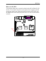
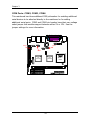
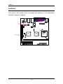
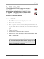
User’s Manual
EPIA-PE
Version 1.01
November 15, 2006
Copyright
Copyright © 2003-2006 VIA Technologies Incorporated. All rights reserved.
No part of this document may be reproduced, transmitted, transcribed, stored in a retrieval
system, or translated into any language, in any form or by any means, electronic, mechanical,
magnetic, optical, chemical, manual or otherwise without the prior written permission of VIA
Technologies, Incorporated.
Trademarks
All trademarks are the property of their respective holders. PS/2 is a registered trademark of
IBM Corporation. Award BIOS is a registered trademark of Phoenix Technologies Ltd.
Disclaimer
No license is granted, implied or otherwise, under any patent or patent rights of VIA
Technologies. VIA Technologies makes no warranties, implied or otherwise, in regard to this
document and to the products described in this document. The information provided in this
document is believed to be accurate and reliable as of the publication date of this document.
However, VIA Technologies assumes no responsibility for the use or misuse of the information
in this document and for any patent infringements that may arise from the use of this
document. The information and product specifications within this document are subject to
change at any time, without notice and without obligation to notify any person of such change.
FCC-B Radio Frequency Interference Statement
This equipment has been tested and found to comply with the limits for a class B digital
device, pursuant to part 15 of the FCC rules. These limits are designed to provide reasonable
protection against harmful interference when the equipment is operated in a commercial
environment. This equipment generates, uses and can radiate radio frequency energy and, if not
installed and used in accordance with the instruction manual, may cause harmful interference
to radio communications. Operation of this equipment in a residential area is likely to cause
harmful interference, in which case the user will be required to correct the interference at his
personal expense.
Notice 1
The changes or modifications not expressly approved by the party responsible for compliance
could void the user's authority to operate the equipment.
Notice 2
Shielded interface cables and A.C. power cord, if any, must be used in order to comply with
the emission limits.
Tested To Comply
With FCC Standards
FOR HOME OR OFFICE USE
Safety Instructions
1.
Always read the safety instructions carefully.
2.
Keep this User's Manual for future reference.
3.
Keep this equipment away from humidity.
4.
Lay this equipment on a reliable flat surface before setting it up.
5.
The openings on the enclosure are for air convection hence protects the equipment from
overheating. DO NOT COVER THE OPENINGS.
6.
Make sure the voltage of the power source and adjust properly 110/220V before
connecting the equipment to the power inlet.
7.
Place the power cord in such a way that people cannot step on it. Do not place anything
over the power cord.
8.
Always unplug the power cord before inserting any add-on card or module.
9.
All cautions and warnings on the equipment should be noted.
10. Never pour any liquid into the opening. Liquid can cause damage or electrical shock.
11. If any of the following situations arises, get the equipment checked by a service personnel:
•
The power cord or plug is damaged
•
Liquid has penetrated into the equipment
•
The equipment has been exposed to moisture
•
The equipment has not work well or you cannot get it work according to User's
Manual.
•
The equipment has dropped and damaged
•
If the equipment has obvious sign of breakage
12. DO NOT LEAVE THIS EQUIPMENT IN AN ENVIRONMENT UNCONDITIONED,
STORAGE TEMPERATURE ABOVE 60 C (140F), IT MAY DAMAGE THE
EQUIPMENT.
CAUTION: Explosion or serious damage may occur if the battery is
incorrectly replaced.
Replace only with the same or equivalent
battery type recommended by the manufacturer.
BOX CONTENTS
One
One
One
One
One
VIA Mini-ITX mainboard
Quick Installation Guide
ATA-133/100 IDE ribbon cable
driver and utilities CD
IO bracket
i
TABLE OF CONTENTS
Specifications ............................................................................. 1
Mainboard Specifications .......................................................... 2
Mainboard Layout .................................................................... 4
Back Panel Layout ................................................................... 4
Installation ................................................................................. 5
CPU........................................................................................ 6
The VIA C3 E-Series Processor .............................................. 6
Fans: CPUFAN, SYSFAN and PWRFAN .................................... 7
Memory Module Installation...................................................... 8
DDR SDRAM Module Installation Procedures ........................... 8
Available DDR SDRAM Configurations................................... 10
Connecting the Power Supply ................................................. 11
ATX 20-Pin Power Connector ............................................... 11
Back Panel Ports.................................................................... 13
Keyboard and Mouse .......................................................... 13
VGA Out ............................................................................ 13
Serial Port: COM 1............................................................. 13
RJ45 10/100 LAN Connector................................................ 14
USB 2.0 Ports..................................................................... 14
LPT Port ............................................................................ 14
Audio Ports:....................................................................... 14
Connectors............................................................................ 15
Hard Disk Connectors: IDE1 & IDE2.................................... 15
Front Panel Connectors: F_PANEL....................................... 16
FIR Module Connector: FIR ................................................ 17
KBMS/CIR Module Connector: KBMS .................................... 18
USB Pin Connector: USB_5/6.............................................. 19
Front Audio Connector: F_AUDIO ....................................... 20
LVDS Connector: LVDS (optional) ........................................ 21
Wake-on Modem: WOM ...................................................... 22
Wake-on LAN: WOL............................................................ 23
COM Ports: COM2, COM3, COM4 ......................................... 24
ii
Digital IO Connector: DIO ................................................... 25
Jumpers................................................................................ 26
Clear CMOS: CLEAR_CMOS ................................................. 27
COM Voltage Select: J3, J4................................................. 28
Slots..................................................................................... 29
Peripheral Component Interconnect: PCI .............................. 29
PCI Interrupt Request Routing............................................. 30
BIOS Setup .............................................................................. 32
Entering Setup ...................................................................... 33
Control Keys.......................................................................... 34
Navigating the BIOS Menus .................................................... 35
Getting Help.......................................................................... 36
Main Menu ............................................................................ 37
Standard CMOS Features .................................................... 37
Advanced BIOS Features..................................................... 37
Advanced Chipset Features ................................................. 37
Integrated Peripherals ........................................................ 37
Power Management Setup................................................... 37
PnP/PCI Configurations ....................................................... 37
PC Health Status ................................................................ 38
Frequency/Voltage Control .................................................. 38
Load Fail-Safe Defaults ....................................................... 38
Load Optimized Defaults ..................................................... 38
Set Supervisor Password ..................................................... 38
Set User Password.............................................................. 38
Save & Exit Setup............................................................... 38
Exit Without Saving ............................................................ 38
Standard CMOS Features........................................................ 39
Date.................................................................................. 39
Time ................................................................................. 39
Halt On ............................................................................. 39
IDE Drives ............................................................................ 40
Advanced BIOS Features ........................................................ 41
iii
Virus Warning .................................................................... 41
CPU L2 Cache ECC Checking ............................................... 41
Processor Number Feature .................................................. 41
Quick Power On Self-Test.................................................... 42
First/Second/Third Boot Device............................................ 42
Boot Other Device .............................................................. 43
Boot Up NumLock Status..................................................... 43
Typematic Rate Setting....................................................... 43
Typematic Rate (Chars/Sec) ................................................ 43
Typematic Delay (Msec)...................................................... 43
Security Option .................................................................. 44
Display Full Screen Logo ..................................................... 44
Show Summary Information ................................................ 44
Display Small Logo ............................................................. 44
Advanced Chipset Features..................................................... 45
AGP Aperture Size .............................................................. 45
AGP Mode (External) .......................................................... 46
AGP Fast Write................................................................... 46
CPU to PCI POST Write ....................................................... 46
Select Display Device .......................................................... 46
Panel Select ....................................................................... 46
CPU Direct Access FB.......................................................... 47
Integrated Peripherals............................................................ 48
Onboard IDE Channel 1/2 .................................................. 48
IDE Prefetch Mode ............................................................. 48
Display Card Priority ........................................................... 48
Frame Buffer Size............................................................... 49
AC97 Audio........................................................................ 49
VIA OnChip LAN ................................................................. 49
USB Keyboard Support........................................................ 49
VIA Onboard LAN ............................................................... 49
Onboard Lan Boot ROM ...................................................... 49
Super IO Device .................................................................... 50
iv
Onboard Serial Port 1/2/3/4 ................................................ 50
Onboard Parallel Port.......................................................... 50
Parallel Port Mode .............................................................. 51
EPP Mode Select ................................................................ 51
ECP Mode Use DMA ............................................................ 51
Onboard Fast IR................................................................. 51
Fast IR IRQ........................................................................ 51
Fast IR DMA ...................................................................... 52
Power Management Setup...................................................... 53
ACPI Suspend Type ............................................................ 53
HDD Power Down............................................................... 53
Power Management Timer .................................................. 54
Video Off Option ................................................................ 54
Power Off by PWRBTN........................................................ 54
Run VGABIOS if S3 Resume ................................................ 54
AC Loss Auto restart ........................................................... 54
Peripherals Activities .............................................................. 55
VGA Event ......................................................................... 55
LPT & COM Event ............................................................... 55
HDD & FDD Event .............................................................. 55
PCI Master Event................................................................ 55
PS2KB Wakeup Select ......................................................... 56
PS2 Mouse Wakeup from S3/S4/S5 ...................................... 56
PS2 KB Wakeup from S3/S4/S5 ........................................... 56
USB Resume ...................................................................... 56
PowerOn by PCI Card ......................................................... 56
Wake On Lan/Ring Connector.............................................. 57
RTC Alarm Resume............................................................. 57
Date (of Month) ................................................................. 57
Resume Time (hh:mm:ss) ................................................... 57
IRQs Activities ....................................................................... 58
Primary INTR ..................................................................... 58
IRQ3~IRQ15...................................................................... 58
v
PNP/PCI Configurations.......................................................... 59
PNP OS Installed ................................................................ 59
Reset Configuration Data .................................................... 59
Resource Controlled By ....................................................... 60
Assign IRQ For VGA/USB..................................................... 60
IRQ Resources ...................................................................... 61
PC Health Status.................................................................... 62
Frequency / Voltage Control ................................................... 63
DRAM Clock ....................................................................... 63
DRAM Timing ..................................................................... 63
DRAM CAS Latency............................................................. 64
Bank Interleave.................................................................. 64
Precharge to Active (Trp) .................................................... 64
Active to Precharge (Tras)................................................... 64
Active to CMD (Trcd) .......................................................... 64
DRAM Burst Len ................................................................. 65
DRAM Voltage .................................................................... 65
CPU Ratio .......................................................................... 65
Spread Spectrum................................................................ 65
Load Fail-Safe Defaults .......................................................... 66
Load Optimized Defaults ........................................................ 67
Set Supervisor / User Password .............................................. 68
Save & Exit Setup .................................................................. 70
Exit Without Saving ............................................................... 71
Driver Installation ..................................................................... 72
Driver Utilities ....................................................................... 73
Getting Started .................................................................. 73
Running the Driver Utilities CD ............................................ 74
CD Content ........................................................................... 75
vi
CHAPTER 1
Specifications
The ultra-compact and highly integrated VIA EPIA-PE uses the MiniITX mainboard form-factor developed by VIA Technologies, Inc. as
part of the company’s open industry-wide Total Connectivity
initiative. The mainboard enables the creation of an exciting new
generation of small, ergonomic, innovative and affordable embedded
systems. Through a high level of integration, the Mini-ITX occupies
66% of the size of FlexATX mainboard form factor. The mainboard
comes with an embedded VIA Processor, boasting of ultra-low power
consumption, cool and quiet operation.
1
Chapter 1
MAINBOARD SPECIFICATIONS
CPU
•
VIA C3 EBGA Processor
Chipset
•
VIA CLE266 North Bridge
•
VIA VT8235M South Bridge
Graphics
•
Integrated VIA Unichrome AGP graphics with MPEG-2 Accelerator
Audio
•
VIA VT1612A AC'97 Codec
Memory
•
1 x DDR266 DIMM slot (up to 1GB)
Expansion Slot
•
1 x PCI slot
•
2 x UltraDMA 66/100/133 connectors
IDE
LAN
•
VIA VT6106S + VT6103 10/100 Base-T Ethernet PHY
2
Specifications
Back Panel I/O Ports
•
1 x PS/2 mouse port and 1 x PS/2 keyboard port
•
2 x RJ-45 LAN port
•
1 x Serial port
•
1 x Parallel port
•
4 x USB 2.0 ports
•
1 x VGA port
•
3 x Audio ports: Line-out, Line-in and Mic-in
Onboard I/O Connectors
•
1 x USB pin headers for 2 additional USB 2.0 ports
•
1 x Front panel audio pinheader (Line-out and Mic-in)
•
1 x FIR pin header
•
1 x CIR pin header (Switchable for KB/MS)
•
1 x LVDS connector
•
3 x COM pin headers
•
1 x Digital IO connector
•
1 x Wake-on Modem connector
•
1 x Wake-on LAN connector
•
3 x Fan connectors
BIOS
•
Award BIOS with 2/4 Mbit flash memory capacity
Form Factor
•
Mini-ITX (6 layers)
•
17 cm X 17 cm
3
Chapter 1
MAINBOARD LAYOUT
DIO
SYSFAN
COM4
F_AUDIO
J3
J4
KBMS
FIR
PWRFAN
COM2
COM3
LVDS
USB_5/6
JC
PCI
CLEAR_CMOS
VIA
CLE266
VIA
VT8235M
C3
EBGA
CPUFAN
WOL
DIM1
F_PANEL
IDE1
IDE2
ATXPWR
I2C
BACK PANEL LAYOUT
LPT
LAN
Line-in
Mouse
Line-out
Keyboard
Mic-in
VGA
COM
4
USB
CHAPTER 2
Installation
This chapter provides you with information about hardware
installation procedures. It is recommended to use a grounded wrist
strap before handling computer components. Electrostatic discharge
(ESD) can damage some components.
5
Chapter 3
CPU
The VIA C3 E-Series Processor
The VIA EPIA-PE Mini-ITX mainboard includes an embedded VIA C3 or Eden
Processor. The VIA C3 Processor provides ultra-low power consumption and
advanced thermal dissipation properties. The VIA C3 Processor requires
heatsink and a CPU fan to provide sufficient cooling. Ensure that the CPU
fan is correctly installed as shown.
WARNING: This mainboard is not designed to support overclocking.
Any attempt to operate beyond product specifications is not
recommended.
We do not guarantee against damages or risks
caused by inadequate operation or beyond product specifications.
6
BIOS Setup
Fans: CPUFAN, SYSFAN and PWRFAN
The CPUFAN (CPU fan), SYSFAN (system fan) and PWRFAN (power fan) run
on +12V and maintain system cooling. When connecting the wire to the
connectors, always be aware that the red wire is the Positive and should be
connected to the +12V. The black wire is Ground and should always be
connected to GND. The CPU system and power fan connectors have sensors
to support fan monitoring.
PWRFAN
SYSFAN
VIA
VT8235M
VIA
CLE266
7
C3
EBGA
CPUFAN
Chapter 3
MEMORY MODULE INSTALLATION
The VIA EPIA-PE Mini-ITX mainboard provides one 184-pin DIMM slot for
DDR266 SDRAM memory modules and supports memory sizes up to 1GB per
slot.
DDR SDRAM Module Installation Procedures
•
Locate the DIMM socket in the motherboard.
VIA
VT8235M
VIA
CLE266
C3
EBGA
DIM1
8
BIOS Setup
•
Unlock a DIMM socket by pressing the retaining clips outward.
•
Align a DIMM on the socket such that the notch on the DIMM
matches the break on the socket.
•
Firmly insert the DIMM into the socket until the retaining clips snap
back in place and the DIMM is properly seated.
9
Chapter 3
Available DDR SDRAM Configurations
Refer to the table below for available DDR SDRAM configurations on the
mainboard.
Slot
Module Size
Total
DIMM 1
64MB, 128MB, 256MB, 512MB, 1GB
Maximum supported system memory
10
64MB-1GB
1GB
BIOS Setup
CONNECTING THE POWER SUPPLY
The VIA EPIA-PE Mini-ITX mainboard supports a conventional ATX power
supply for the power system. Before inserting the power supply connector,
always make sure that all components are installed correctly to ensure that
no damage will be caused.
ATX 20-Pin Power Connector
To connect the ATX power supply, make sure the power plug is inserted in
the proper orientation and the pins are aligned. Then push down the plug
firmly into the connector.
VIA
VT8235M
VIA
CLE266
C3
EBGA
ATXPWR
11
Chapter 3
ATX 20 Pin Power Connector
Pin
Signal
Pin
Signal
1
2
3
4
5
6
7
8
9
10
+3.3V
+3.3V
GND
+5V
GND
+5V
GND
Power Good
+5V Standby
+12V
11
12
13
14
15
16
17
18
19
20
+3.3V
-12V
GND
Power Supply On
GND
GND
GND
NC
+5V
+5V
12
BIOS Setup
BACK PANEL PORTS
The back panel has the following ports:
Keyboard and Mouse
The green 6-pin connector is for a PS/2 mouse. The purple
connector is for a PS/2 keyboard.
VGA Out
The 15-pin female VGA connector can be used to
connect to any analog VGA monitor.
Serial Port: COM 1
This 9-pin COM 1 port is for pointing devices or other
serial devices.
13
Chapter 3
RJ45 10/100 LAN Connector
The mainboard provides a standard RJ-45 port. This port allows
connection to a Local Area Network (LAN) through a network hub
USB 2.0 Ports
These four 4-pin Universal Serial Bus (USB) ports are available for
connecting USB 2.0 devices.
LPT Port
The 25-pin female parallel port for connecting
printers supports Enhanced Parallel Port and
Extended Capabilities Port modes.
Audio Ports:
Line Out
This Line Out (lime) jack connects a headphone or a speaker.
Line In
This Line In (light blue) jack connects a tape player or other audio devices.
Microphone
This Mic (pink) jack connects a microphone.
14
BIOS Setup
CONNECTORS
Hard Disk Connectors: IDE1 & IDE2
The two IDE connectors support Ultra DMA 66/100/133 modes. Both IDE
connectors can connect a master and a slave drive. The IDE connectors can
support up to four IDE devices.
If two drives are connected to a single cable, the jumper on the second
drive must be set to slave mode. Refer to the drive documentation supplied
by the vendor for the jumper settings.
VIA
VT8235M
VIA
CLE266
IDE1
IDE2
15
C3
EBGA
Chapter 3
Front Panel Connectors: F_PANEL
The J3 pin header allows you to connect the power switch, reset switch,
power LED, HDD LED and the case speaker.
Pin
Signal
Pin
Signal
1
3
5
7
9
11
HDD LED+
HDD LEDPower Switch
Power Switch
Reset Switch
Reset Switch
2
4
6
8
10
12
Power LED+
N/A
Power LEDN/A
N/A
N/A
VIA
CLE266
VIA
VT8235M
Front Panel
Connector
16
C3
EBGA
BIOS Setup
FIR Module Connector: FIR
This pin header is used to connect to a Fast IrDA module.
settings must be configured to activate the IR function.
Pin
Signal
Description
1
2
3
4
5
+3V
IRRX
IRRX2
GND
IRTX
VCC
FIR/SIR Data Receive
SIR Data Receive
Ground
FIR/SIR Data Transmit
FIR
VIA
VT8235M
VIA
CLE266
17
C3
EBGA
The BIOS
Chapter 3
KBMS/CIR Module Connector: KBMS
This pin header is used to connect to a Consumer IrDA module.
Pin
Signal
Pin
Signal
1
3
5
7
9
+5V
KB_CLK
EKBCLK
MS_CLK
EMCLK
2
4
6
8
10
GND
KB_DATA
EKBDATA
MS_DATA
EMDATA
Keyboard and Mouse
or CIR
VIA
VT8235M
VIA
CLE266
18
C3
EBGA
BIOS Setup
USB Pin Connector: USB_5/6
The mainboard provides 1 front USB pin header connectors, allowing up to 2
additional USB 1.1 ports.
Connect each 2-port USB cable into each pin
headers. These ports can be used to connect USB interface peripherals such
as USB HDD, digital cameras, MP3 players, printers, modem, etc.
Pin
Signal
Pin
Signal
1
3
5
7
9
VCC
USB2USB2+
GND
NC
2
4
6
8
10
VCC
USB3USB3+
GND
GND
USB connector
VIA
VT8235M
VIA
CLE266
19
C3
EBGA
Chapter 3
Front Audio Connector: F_AUDIO
This connector allows you to connect a front audio panel to the mainboard.
Only the line-out and microphone functions are available for use on the front
panel. To connect the front audio cable, first remove the two red plastic
jumpers.
Pin
Signal
Pin
Signal
1
3
5
7
9
FRN_MIC
AUD_MIC_BIAS
LINE_OUT_R
NC
LINE_OUT_L
2
4
6
8
10
AGND
+5V
NEXT_R
Key
NEXT_L
F_AUDIO
VIA
CLE266
VIA
VT8235M
20
C3
EBGA
BIOS Setup
LVDS Connector: LVDS (optional)
This connector is for devices requiring access to the signals listed in the
table below. The LVDS connector may not be available on your mainboard.
This is an option that is added during the manufacturing process. If you
would like a mainboard with the LVDS connector, please contact your
vendor or sales contact for more information.
LVDS
VIA
VT8235M
VIA
CLE266
21
C3
EBGA
Chapter 3
Wake-on Modem: WOM
The Wake-on Modem connector enables a modem with the Wake-on Modem
feature to power up the system when a ring-in signal is received through the
modem.
Wake-on
Modem
VIA
VT8235M
VIA
CLE266
22
C3
EBGA
BIOS Setup
Wake-on LAN: WOL
This connector allows you to connect a network card with the Wake-On LAN
function. The connector will power up the system when a signal is received
through the network card. Please note that the function of ACPI WOL may
be disabled when users unplug the power cord or turn off the power button
manually.
VIA
CLE266
VIA
VT8235M
Wake-on
LAN
23
C3
EBGA
Chapter 3
COM Ports: COM2, COM3, COM4
This mainboard has three additional COM pinheaders for enabling additional
serial devices to be attached directly to the mainboard or for adding
additional serial ports. COM3 and COM4 pin headers have their own voltage
select jumper that enables support between either 5V or 12V. See the
jumper settings for more information.
COM3
COM2
COM4
VIA
CLE266
VIA
VT8235M
24
C3
EBGA
BIOS Setup
Digital IO Connector: DIO
This connector provides four GPI (General Purpose Input) and four GPO
(General Purpose Output) pin headers for supporting both 5V and 12V
Digital IO solutions.
DIO
VIA
VT8235M
VIA
CLE266
25
C3
EBGA
Chapter 3
JUMPERS
The mainboard provides jumpers for setting some mainboard functions.
This section will explain how to change the settings of the mainboard
functions using the jumpers.
J3
J4
CLEAR_CMOS
VIA
CLE266
VIA
VT8235M
26
C3
EBGA
BIOS Setup
Clear CMOS: CLEAR_CMOS
This jumper allows you to clear the Real Time Clock (RTC)
RAM in CMOS. You can clear the CMOS memory of date,
time and system setup parameters by erasing the CMOS
RTC RAM data. The onboard button cell battery powers
the RAM data in CMOS that include system setup
information such as system passwords.
Keep
1 2 3
Clear
1 2 3
To erase the RTC RAM:
1.
Turn OFF the computer and unplug the power cord.
2.
Remove the onboard battery
3.
Move the jumper cap from pins 2-3 (default) to pins 1-2. Keep cap
on pins 1-2 for about 5~10 seconds, then move the cap back to pins
2-3.
4.
Replace the battery.
5.
Plug the power cord and turn ON the computer.
6.
Hold down the <Del> key during the boot process and enter BIOS
setup to re-enter data.
WARNING: Except when clearing the RTC RAM, never remove the
cap on CLEAR_CMOS jumper default position. Removing the cap
will cause system boot failure. Avoid clearing the CMOS while the
system is on; it will damage the mainboard.
27
Chapter 3
COM Voltage Select: J3, J4
5V
This jumper changes the voltage for COM3 and COM4
respectively. Voltage options are 5V and 12V.
Pins
Voltage
1-2
2-3
+5V
+12V
1 2 3
12V
1 2 3
28
BIOS Setup
SLOTS
Peripheral Component Interconnect: PCI
The PCI slot allows you to insert PCI expansion card.
When adding or
removing expansion card, first unplug the power supply.
Read the
documentation for the expansion card if any changes to the system are
necessary.
PCI
VIA
CLE266
VIA
VT8235M
29
C3
EBGA
Chapter 3
PCI Interrupt Request Routing
The IRQ (interrupt request line) are hardware lines over which devices can
send interrupt signals to the microprocessor. The “PCI & LAN” IRQ pins are
typically connected to the PCI bus INT A# ~ INT D# pins as follows:
PCI Slot 1
Order 1
Order 2
Order 3
Order 4
INT B#
INT C#
INT D#
INT A#
30
BIOS Setup
This page is intentionally left blank.
31
CHAPTER 3
BIOS Setup
This chapter gives a detailed explanation of the BIOS setup functions.
32
BIOS Setup
ENTERING SETUP
Power on the computer and press <Delete> during the beginning of the
boot sequence to enter the BIOS setup menu. If you missed the BIOS setup
entry point, you may restart the system and try again.
33
Chapter 3
CONTROL KEYS
Keys
Description
Up Arrow
Down Arrow
Left Arrow
Right Arrow
Enter
Escape
Move to the previous item
Move to the next item
Move to the item in the left side
Move to the item in the right side
Select the item
Jumps to the Exit menu or returns to the main menu
from a submenu
Increase the numeric value or make changes
Decrease the numeric value or make changes
General help, only for Status Page Setup Menu and
Option Page Setup Menu
Restore the previous CMOS value from CMOS, only for
Option Page Setup Menu
Load the default CMOS value from Fail-Safe default table,
only for Option Page Setup Menu
Load Optimized defaults
Jumps to the Main Menu
Save all the CMOS changes and exit
Page Up / +
Page Down / F1
F5
F6
F7
F9
F10
34
BIOS Setup
NAVIGATING THE BIOS MENUS
The main menu displays all the BIOS setup categories. Use the control keys
Up/Down arrow keys to select any item/sub-menu.
Description of the
selected/highlighted category is displayed at the bottom of the screen.
An arrow symbol next to a field indicates that a sub-menu is available (see
figure below). Press <Enter> to display the sub-menu. To exit the submenu, press <Esc>.
35
Chapter 3
GETTING HELP
The BIOS setup program provides a “General Help” screen. You can display
this screen from any menu/sub-menu by pressing <F1>. The help screen
displays the keys for using and navigating the BIOS setup. Press <Esc> to
exit the help screen.
36
BIOS Setup
MAIN MENU
Standard CMOS Features
Use this menu to set basic system configurations.
Advanced BIOS Features
Use this menu to set the advanced features available on your system.
Advanced Chipset Features
Use this menu to set chipset specific features and optimize system
performance.
Integrated Peripherals
Use this menu to set onboard peripherals features.
Power Management Setup
Use this menu to set onboard power management functions.
PnP/PCI Configurations
Use this menu to set the PnP and PCI configurations.
37
Chapter 3
PC Health Status
This menu shows the PC health status.
Frequency/Voltage Control
Use this menu to set the system frequency and voltage control.
Load Fail-Safe Defaults
Use this menu option to load the BIOS default settings for minimal and
stable system operations.
Load Optimized Defaults
Use this menu option to load BIOS default settings for optimal and high
performance system operations.
Set Supervisor Password
Use this menu option to set the BIOS supervisor password.
Set User Password
Use this menu option to set the BIOS user password.
Save & Exit Setup
Save BIOS setting changes and exit setup.
Exit Without Saving
Discard all BIOS setting changes and exit setup.
38
BIOS Setup
STANDARD CMOS FEATURES
Date
The date format is [Day, Month Date Year]
Time
The time format is [Hour : Minute : Second]
Halt On
Sets the system’s response to specific boot errors. Below is a table that
details the possible settings.
Setting
Description
All Errors
No Errors
All but Keyboard
System halts when any error is detected
System does not halt for any error
System halts for all non-key errors
39
Chapter 3
IDE DRIVES
The specifications of your drive must match with the drive table. The hard
disk will not work properly if you enter incorrect information in this category.
Select “Auto” whenever possible.
If you select “Manual”, make sure the
information is from your hard disk vendor or system manufacturer. Below is
a table that details required hard drive information when using the “Manual”
mode.
Setting
Description
IDE Channel
The name of this item will match the name of the menu
(e.g. IDE Primary Master).
Settings: [None, Auto, Manual]
Settings: [CHS, LBA, Large, Auto]
Formatted size of the storage device
Number of cylinders
Number of heads
Write precompensation
Cylinder location of the landing zone
Number of sectors
Settings: [Auto, 0, 1, 2, 3, 4]
Settings: [Auto, Disabled]
Access Mode
Capacity
Cylinder
Head
Precomp
Landing Zone
Sector
PIO Mode
Ultra DMA Mode
40
BIOS Setup
ADVANCED BIOS FEATURES
Virus Warning
Setting
Description
Enabled
Disabled
Turns on hard disk boot sector virus protection
Turns off hard disk boot sector virus protection
CPU L2 Cache ECC Checking
Setting
Description
Enabled
Disabled
Enables ECC for L2 cache
Disables ECC for L2 cache
Processor Number Feature
This is only valid for CPUs that have a processor number.
Setting
Description
Enabled
Disabled
Enables access to the CPU’s embedded unique ID number.
Disables access to the CPU’s embedded unique ID number.
41
Chapter 3
Quick Power On Self-Test
Shortens Power On Self-Test (POST) cycle to enable shorter boot up time.
Setting
Description
Enabled
Disabled
Shorten Power On Self Test (POST) cycle and bootup time
Standard Power On Self Test (POST)
First/Second/Third Boot Device
Set the boot device sequence as BIOS attempts to load the disk operating
system.
Setting
Description
LS120
HDD-0
SCSI
CDROM
HDD-1
HDD-2
HDD-3
ZIP100
USB-FDD
USB-ZIP
USB-CDROM
USB-HDD
LAN
Disabled
Boot from LS-120 drive
Boot from the first HDD
Boot from SCSI
Boot from CD-ROM
Boot from the second HDD
Boot from the third HDD
Boot from the fourth HDD
Boot from ATAPI ZIP drive
Boot from USB floppy drive
Boot from USB ZIP drive
Boot from USB CDROM
Boot from the USB HDD.
Boot from network drive
Disable the boot device sequence
42
BIOS Setup
Boot Other Device
Enables the system to boot from alternate devices if the system fails to boot
from the “First/Second/Third Boot Device” list.
Setting
Description
Enabled
Disabled
Enable alternate boot device
No alternate boot device allowed
Boot Up NumLock Status
Set the NumLock status when the system is powered on.
Setting
Description
On
Off
Forces keypad to behave as 10-key
Forces keypad to behave as arrow keys
Typematic Rate Setting
Enables “Typematic Rate” and “Typematic Delay” functions.
Settings: [Enabled, Disabled]
Typematic Rate (Chars/Sec)
This item sets the rate (characters/second) at which the system retrieves a
signal from a depressed key.
Settings: [6, 8, 10, 12, 15, 20, 24, 30]
Typematic Delay (Msec)
This item sets the delay between when the key was first pressed and when
the system begins to repeat the signal from the depressed key.
Settings: [250, 500, 750, 1000]
43
Chapter 3
Security Option
Selects whether the password is required every time the System boots, or
only when you enter Setup.
Setting
Description
Setup
Password prompt appears only when end users try to run
BIOS Setup
Password prompt appears every time when the computer is
powered on and when end users try to run BIOS Setup
System
Display Full Screen Logo
Show full screen logo during BIOS boot up process.
Settings: [Enabled, Disabled]
Show Summary Information
Show summary screen.
Settings: [Enabled, Disabled]
Display Small Logo
Show small energy star logo during BIOS boot up process.
Settings: [Enabled, Disabled]
44
BIOS Setup
ADVANCED CHIPSET FEATURES
WARNING: The Advanced Chipset Features menu is used for
optimizing the chipset functions.
Do not change these settings
unless you are familiar with the chipset.
AGP Aperture Size
This setting controls how much memory space can be allocated to AGP for
video purposes. The aperture is a portion of the PCI memory address range
dedicated to graphics memory address space. Host cycles that hit the
aperture range are forwarded to the AGP without any translation.
Settings: [4MB, 8MB, 16MB, 32MB, 64MB, 128MB, 256MB]
45
Chapter 3
AGP Mode (External)
This mainboard supports the AGP 4x interface. When the AGP 4x video card
is used, it can transfer video data at 1066MB/s. AGP 4x is backwardcompatible, leave the default 4x mode on if unsure. When set to 1x mode,
the maximum transfer rate it at 266MB/s, and 2x mode transfers data at
533MB/s. AGP8x mode can be detected automatically once you plug in the
AGP8x card.
Settings: [4X, 2X, 1X]
AGP Fast Write
This item is used to enable or disable the caching of display data for the
video memory of the processor.
Settings: [Enabled, Disabled]
CPU to PCI POST Write
When Enabled, CPU can write up to four words of data to the PCI write
buffer before CPU must wait for PCI bus cycle to finish. If Disabled, CPU
must wait after each write cycle until PCI bus signals that it is ready to
receive more data.
Settings: [Enabled, Disabled]
Select Display Device
This setting refers to the type of display being used with the system.
Settings: [CRT, LCD, CRT+LCD, DVI, CRT+DVI]
Panel Select
This setting refers to the native resolution of the display being used with the
system.
Settings: [1600x1200, 1400x1050, 1280x1024, 1280x768,1024x768,
800x600, 640x480]
46
BIOS Setup
CPU Direct Access FB
Controls the CPU’s access to directly access the system memory reserved for
graphics data.
Settings: [Enabled, Disabled]
47
Chapter 3
INTEGRATED PERIPHERALS
Onboard IDE Channel 1/2
The integrated peripheral controller contains an IDE interface with support
for two IDE channels. Choose Enabled to activate each channel separately.
Settings: [Enabled, Disabled]
IDE Prefetch Mode
This allows your hard disk controller to use the fast block mode to transfer
data to and from the hard disk drive. Block mode is also called block transfer,
multiple commands or multiple sector read/write. Enabled enables IDE
controller to use block mode; Disabled allows the controller to use standard
mode.
Settings: [Enabled, Disabled]
Display Card Priority
This setting specifies which VGA card is your primary graphics adapter.
Settings: [PCI Slot, AGP]
48
BIOS Setup
Frame Buffer Size
This setting instructs the BIOS to reserve the specified amount of memory
for the internal video controller.
Settings: [16M, 32M, 64M]
AC97 Audio
Auto allows the mainboard to detect whether an audio device is used. If the
device is detected, the onboard VIA AC'97 (Audio Codec'97) controller will
be enabled; if not, it is disabled. Disable the controller if you want to use
other controller cards to connect to an audio device.
Settings: [Auto, Disabled]
VIA OnChip LAN
This setting allows you to make VIA OnChip LAN enabled or disabled.
Settings: [Enabled, Disabled]
USB Keyboard Support
Enable USB Keyboard Support for DOS and Windows.
Settings: [Enabled, Disabled]
VIA Onboard LAN
Enables the onboard LAN controller.
Settings: [Enabled, Disabled]
Onboard Lan Boot ROM
Enable Onboard Lan Boot ROM for DOS and Windows.
Settings: [Enabled, Disabled]
49
Chapter 3
SUPER IO DEVICE
Onboard Serial Port 1/2/3/4
Set the base I/O port address and IRQ for the onboard serial port A/serial
port B. Selecting Auto allows BIOS to automatically determine the correct
base I/O port address.
Port
Settings
1
2
3
4
Disabled
Disabled
Disabled
Disabled
3F8
3F8
3F8
3F8
IRQ4
IRQ4
IRQ5
IRQ5
2F8
2F8
2F8
2F8
IRQ3
IRQ3
IRQ10
IRQ10
3E8
3E8
3E8
3E8
IRQ4
IRQ4
IRQ5
IRQ5
2E8
2E8
2E8
2E8
IRQ3
IRQ3
IRQ10
IRQ10
Auto
Auto
—
—
Onboard Parallel Port
This specifies the I/O port address and IRQ of the onboard parallel port.
Settings: [Disabled, 378/IRQ7, 278/IRQ5, 3BC/IRQ7]
50
BIOS Setup
Parallel Port Mode
Set the parallel port mode.
To operate the onboard parallel port as
Standard Parallel Port, choose SPP. To operate the onboard parallel port in
the EPP mode, choose EPP. By choosing ECP, the onboard parallel port will
operate in ECP mode. Choosing ECP + EPP will allow the onboard parallel
port to support both the ECP and EPP modes simultaneously.
Settings: [SPP, EPP, ECP, ECP + EPP]
EPP Mode Select
EPP (Enhanced Parallel Port) comes in two modes: 1.9 and 1.7. EPP 1.9 is
the newer version of the protocol and is backwards compatible with most
EPP devices. If your EPP device does not work with the EPP 1.9 setting, try
changing the setting to EPP 1.7.
Settings: [EPP 1.9, EPP 1.7]
ECP Mode Use DMA
ECP (Extended Capabilities Port) has two DMA channels that it can use. The
default channel is 3. However, some expansion cards may use channel 3 as
well. To solve this conflict, change the ECP channel to 1. Select a DMA
channel for the port.
Settings: [1, 3]
Onboard Fast IR
Enables the onboard FIR.
Settings: [Enabled, Disabled]
Fast IR IRQ
Set this field to reserve an IRQ for the Fast IR port. This field is only
available if Onboard Fast IR is enabled.
Settings: [3, 4, 5, 11]
51
Chapter 3
Fast IR DMA
Set this field to choose the DMA channel. This field is only available if
Onboard Fast IR is enabled.
Settings: [6, 5]
52
BIOS Setup
POWER MANAGEMENT SETUP
ACPI Suspend Type
Setting
Description
S1(POS)
S1/Power On Suspend (POS) is a low power state. In this
state, no system context (CPU or chipset) is lost and
hardware maintains all system contexts.
S3/Suspend To RAM (STR) is a power-down state. In this
state, power is supplied only to essential components such as
main memory and wakeup-capable devices. The system
context is saved to main memory, and context is restored
from the memory when a "wakeup" event occurs.
Depends on the OS to select S1 or S3.
S3(STR)
S1 & S3
HDD Power Down
Sets the length of time for a period of inactivity before powering down the
hard disk.
Settings: [Disabled, 1~15(minutes)]
53
Chapter 3
Power Management Timer
Set the idle time before system enters power saving mode. ACPI OS such as
Windows XP will override this option.
Settings: [Disabled, 1/2/4/6/8/10/20/30/40 (minutes), 1 (hour)]
Video Off Option
Select whether or not to turn off the screen when system enters power
saving mode, ACPI OS such as Windows XP will override this option.
Setting
Description
Always On
Screen is always on even when system enters power
saving mode
Screen is turned off when system enters power saving
mode
Suspend -> Off
Power Off by PWRBTN
This field configures the power button on the chassis.
Setting
Description
Delay 4 Sec
System is turned off if power button is pressed for more than
four seconds
Power button functions as a normal power-on/-off button
Instant-Off
Run VGABIOS if S3 Resume
Select whether to run VGA BIOS if resumed from S3 state. This is only
necessary for older VGA drivers, select Auto if in doubt.
Settings: [Auto, Yes, No]
AC Loss Auto restart
The field defines how the system will respond after an AC power loss during
system operation.
Setting
Description
Off
Keeps the system in an off state until the power button is
pressed
Restarts the system when the power is back
On
54
BIOS Setup
PERIPHERALS ACTIVITIES
VGA Event
Enables the power management unit to monitor VGA activities.
Settings: [Off, On]
LPT & COM Event
Decide whether or not the power management unit should monitor parallel
port (LPT) and serial port (COM) activities.
Settings: [None, LPT, COM, LPT / COM]
HDD & FDD Event
Enables the power management unit to monitor hard disk and floppy disk
activities.
Settings: [Off, On]
PCI Master Event
Enables the power management unit to monitor PCI master activities.
Settings: [Off, On]
55
Chapter 3
PS2KB Wakeup Select
When select Password, please press Page Up or Page Down key to change
Password, 8 characters maximum. Please note that PS2MS Wakeup from
suspend and PS2KB Wakeup from suspend will be disabled while changing
the passward.
Settings: [Hot key, Password]
PS2 Mouse Wakeup from S3/S4/S5
Enables any mouse activity to restore the system from the power saving
mode to an active state.
Settings: [Disabled, Enabled]
PS2 KB Wakeup from S3/S4/S5
Enables any keyboard activity to restore the system from the power saving
mode to an active state.
Settings: [Disabled, Enabled]
USB Resume
Enables activity detected from USB devices to restore the system from a
suspended state to an active state.
Settings: [Disabled, Enabled]
PowerOn by PCI Card
Enables activity detected from any PCI card to power up the system or
resume from a suspended state. Such PCI cards include LAN, onboard USB
ports, etc.
Settings: [Disabled, Enabled]
NOTE: EPIA PE does not support the wake up function of a PCI
Network card from the PCI PME (Power Management Event) bus.
56
BIOS Setup
Wake On Lan/Ring Connector
Decide whether or not any Ring-In signals from the modem can wake up the
system or resume from suspend state.
Settings: [Disabled, Enabled]
RTC Alarm Resume
Sets a scheduled time and/or date to automatically power on the system.
Settings: [Disabled, Enabled]
Date (of Month)
The field specifies the date for “RTC Alarm Resume”.
Resume Time (hh:mm:ss)
The field specifies the time for “RTC Alarm Resume”.
57
Chapter 3
IRQS ACTIVITIES
Primary INTR
Restores the system to an active state if IRQ activity is detected from any of
the enabled channels
Settings: [Off, On]
IRQ3~IRQ15
Enables or disables the monitoring of the specified IRQ line. These fields
are only available if “Primary INTR” is on.
Settings: [Enabled, Disabled]
NOTE: IRQ (Interrupt Request) lines are system resources allocated
to I/O devices. When an I/O device needs to gain attention of the
operating system, it signals this by causing an IRQ to occur. After
receiving the signal, when the operating system is ready, the system
will interrupt itself and perform the service required by the IO device.
58
BIOS Setup
PNP/PCI CONFIGURATIONS
NOTE:
This section covers some very technical items and it is
strongly recommended to leave the default settings as is unless you
are an experienced user.
PNP OS Installed
Setting
Description
Yes
BIOS will only initialize the PnP cards used for booting
(VGA, IDE, SCSI). The rest of the cards will be initialized
by the PnP operating system
BIOS will initialize all the PnP cards
No
Reset Configuration Data
This field should usually be left “Disabled”.
Setting
Description
Enabled
Resets the ESCD (Extended System Configuration Data)
after exiting BIOS Setup if a newly installed PCI card or
the system configuration prevents the operating system
from loading
Default setting
Disabled
59
Chapter 3
Resource Controlled By
Enables the BIOS to automatically configure all the Plug-and-Play compatible
devices.
Setting
Description
Auto(ESCD)
BIOS will automatically assign IRQ, DMA and memory
base address fields
Unlocks “IRQ Resources” for manual configuration
Manual
Assign IRQ For VGA/USB
Assign IRQ for VGA and USB devices.
Settings: [Disabled, Enabled]
60
BIOS Setup
IRQ RESOURCES
NOTE: The items are adjustable only when “Resources Controlled
By” is set to “Manual.”
IRQ Resources list IRQ 3/4/5/7/9/10/11/12/14/15 for users to set each IRQ
a type depending on the type of device using the IRQ.
Setting
Description
PCI Device
For Plug-and-Play compatible devices designed for PCI bus
architecture
The IRQ will be reserved for other requests
Reserved
61
Chapter 3
PC HEALTH STATUS
The PC Health Status displays the current status of all of the monitored
hardware devices/components such as CPU voltages, temperatures and fan
speeds.
62
BIOS Setup
FREQUENCY / VOLTAGE CONTROL
DRAM Clock
The chipset supports synchronous and asynchronous mode between host
clock and DRAM clock frequency.
Settings: 66 MHz, 100 MHz, 133 MHz, By SPD
DRAM Timing
The value in this field depends on the memory modules installed in your
system. Changing the value from the factory setting is not recommended
unless you install new memory that has a different performance rating than
the original modules.
Settings: [Manual, By SPD]
63
Chapter 3
DRAM CAS Latency
This item adjusts the speed it takes for the memory module to complete a
command. Generally, a lower setting will improve the performance of your
system. However, if your system becomes less stable, you should change it
to a higher setting. This field is only available when DRAM Timing is set to
Manual.
Settings: [2, 2.5]
Bank Interleave
Set the interleave mode of the SDRAM interface. Interleaving allows banks
of SDRAM to alternate their refresh and access cycles. One bank will
undergo its refresh cycle while another is being accessed. This improves
performance of the SDRAM by masking the refresh time of each bank. This
field is only available when DRAM Timing is set to Manual.
Settings: [Disabled, 2 Bank, 4 Bank]
Precharge to Active (Trp)
This field controls the length of time it takes to precharge a row in the
memory module before the row becomes active. Longer values are safer but
may not offer the best performance. This field is only available when DRAM
Timing is set to Manual.
Settings: [2T, 3T]
Active to Precharge (Tras)
This field controls the length of time it a row stays active before
precharging. Longer values are safer buy may not offer the best
performance. This field is only available when DRAM Timing is set to Manual.
Settings: [5T, 6T]
Active to CMD (Trcd)
This field is only available when DRAM Timing is set to Manual.
Settings: [2T, 3T]
64
BIOS Setup
DRAM Burst Len
This field sets the length of time for one burst of data during a read/write
transaction. Longer settings equals better memory performance.
Settings: [4, 8]
DRAM Voltage
This field sets the voltage for the memory module.
Settings: [2.7V, 2.6V, 2.5V, Default]
CPU Ratio
Settings: [Default, x3, x3.5, x4, x4.5, x5, x5.5, x6, x6.5, x7, x7.5, x8, x8.5,
x9, x9.5, x10, x10.5, x11, x11.5, x12, x13, x14, x15, x16]
Spread Spectrum
When the mainboard's clock generator pulses, the extreme values (spikes)
of the pulses creates EMI (Electromagnetic Interference). The Spread
Spectrum function reduces the EMI generated by modulating the pulses so
that the spikes of the pulses are reduced to flatter curves.
65
Chapter 3
LOAD FAIL-SAFE DEFAULTS
This option is for restoring all the default fail-safe BIOS settings.
These
values are set by the mainboard manufacturer to provide a stable system
with basic performance.
Entering “Y” loads the default fail-safe BIOS values.
66
BIOS Setup
LOAD OPTIMIZED DEFAULTS
This option is for restoring all the default optimized BIOS settings.
The
default optimized values are set by the mainboard manufacturer to provide a
stable system with optimized performance.
Entering “Y” loads the default optimized BIOS values.
67
Chapter 3
SET SUPERVISOR / USER PASSWORD
This option is for setting a password for entering BIOS Setup.
When a
password has been set, a password prompt will be displayed whenever BIOS
Setup is run. This prevents an unauthorized person from changing any part
of your system configuration.
There are two types of passwords you can set. A supervisor password and a
user password.
When a supervisor password is used, the BIOS Setup
program can be accessed and the BIOS settings can be changed. When a
user password is used, the BIOS Setup program can be accessed but the
BIOS settings cannot be changed.
To set the password, type the password (up to eight characters in length)
and press <Enter>. The password typed now will clear any previously set
password from CMOS memory. The new password will need to be reentered
to be confirmed. To cancel the process press <Esc>.
To disable the password, press <Enter> when prompted to enter a new
password. A message will show up to confirm disabling the password. To
cancel the process press <Esc>.
68
BIOS Setup
Additionally, when a password is enabled, the BIOS can be set to request
the password each time the system is booted.
This would prevent
unauthorized use of the system. See “Security Option” in the “Advanced
BIOS Features” section for more details.
69
Chapter 3
SAVE & EXIT SETUP
Entering “Y” saves any changes made and exits the program.
Entering “N” will cancel the exit request.
70
BIOS Setup
EXIT WITHOUT SAVING
Entering “Y” discards any changes made and exits the program.
Entering “N” will cancel the exit request.
71
CHAPTER 4
Driver Installation
This chapter gives you brief descriptions of each mainboard driver
and application. You must install the VIA chipset drivers first before
installing other drivers such as audio or VGA drivers.
The
applications will only function correctly if the necessary drivers are
already installed.
72
Driver Installation
DRIVER UTILITIES
Getting Started
The mainboard includes a Driver Utilities CD that contains the driver utilities
and software for enhancing the performance of the mainboard. If the CD is
missing from the retail box, please contact the local dealer for the CD.
Note: The driver utilities and software are updated from time to time. The latest
updated versions are available at http://www.viaembedded.com./
73
Chapter 4
Running the Driver Utilities CD
To start using the CD, insert the CD into the CD-ROM or DVD-ROM drive.
The CD should run automatically after closing the CD-ROM or DVD-ROM
drive. The driver utilities and software menu screen should then appear on
the screen. If the CD does not run automatically, click on the “Start” button
and select “Run…” Then type: "D:\Setup.exe".
NOTE: D: might not be the drive letter of the CD-ROM/DVD-ROM in
your system.
74
Driver Installation
CD CONTENT
VIA 4in1 Drivers: Contains VIA ATAPI Vendor Support
Driver (enables the performance enhancing bus mastering
functions on ATA-capable Hard Disk Drives and ensures IDE
device compatibility), AGP VxD Driver (provides service
routines to your VGA driver and interface directly to
hardware, providing fast graphical access), IRQ Routing
Miniport Driver (sets the system's PCI IRQ routing sequence)
and VIA INF Driver (enables the VIA Power Management
function).
VIA Graphics Driver: Enhances the onboard VIA graphic
chip.
VIA Audio Driver: Enhances the onboard VIA audio chip.
VIA USB 2.0 Driver: Enhances VIA USB 2.0 ports.
VIA LAN Driver: Enhances the onboard VIA LAN chip.
VIA FIR Driver: Support for FIR.
Note: The EPIA-PE is packaged with the same driver installation CD
as the EPIA-PD.
75