1
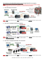
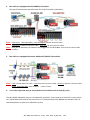
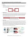
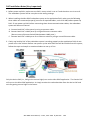
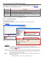
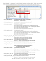
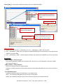
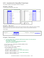
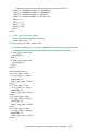
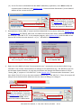
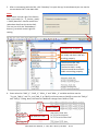
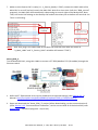
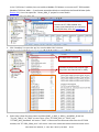
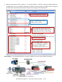
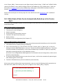
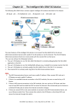
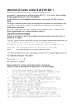
Chapter 16 Redundancy
16.1 Features and Architecture
The ICP DAS Win-GRAF PAC - XP-8xx8-CE6 series support redundancy:
One redundant system is composed by two Win-GRAF PACs that one PAC’s rotary switch is set to 7
(means Main-PAC) and the other one is set to 9 (means Backup-PAC). When one of them is damaged or
crashed or need to release its control-right by user-defined event, the PAC control-right will
automatically switch to the healthy one.
Features of the Win-GRAF redundancy
1. Better safety:
There are three communication cables (LAN1, LAN2 and Alive Port) connected between two PACs.
The redundant system will still control the process well, even if one or two cables are broken or
disconnected. As long as one of the three communication cables is fine, the Win-GRAF redundant
PACs can still work well with the process.
2. Unique Public IP:
The Win-GRAF redundant system provides a unique public IP address for SCADA/HMI to access it
without needing to determine which one is the Active IP.
3. Easy maintenance:
If one of the redundant PACs is damaged someday after starting the process, you can remove the
damaged one (Note: Do not shutdown or dismounting the other healthy PAC, keep it running). And
then take another spare Win-GRAF PAC with the same model (or a repaired PAC) without
downloading the Win-GRAF application, simply adjust its rotary switch to a proper position and then
connect all required communication cables (e.g., LAN1, LAN2, Alive port and I/O). Make sure that the
original, healthy PAC is still working properly and then power up the spare PAC. Then, the healthy
PAC will automatically copy the Win-GRAF app and all its redundant data to that new PAC which is
just online. It is easier for maintenance and installation, the operator don’t have to worry about
whether to install the Win-GRAF app because the healthy PAC will automatically do it for the new
online PAC.
Exception: Except the Win-GRAF app if there are a few apps, such as the C, VB.net, C# app or
Soft-GRAF HMI app, running in the redundant system, these apps need to pre-installed to the spare
Win-GRAF PAC (or a repaired PAC) before installing this PAC to the redundant system.
4. Easy to design the application:
The user has to do is design the application program. Not necessary to specify what data should be
redundant between two PACs. The Win-GRAF redundant system will automatically deliver them to
the other PAC.
5. Users can design some safety in the app:
For example, if the Active PAC’s LAN1 is disconnected (causes the SCADA unable to connect to) or a
RS-485 Port is disconnected or damaged, and so on. The user’s app can test these events and then
switch control right to the other healthy PAC.
6. I/O Redundancy:
If the user chooses iDCS-8830 series I/O, both the PAC and I/O modules can support redundancy.
Win-GRAF User Manual, V 1.02, Mar. 2015 by ICP DAS
16-1
The architecture of the Win-GRAF redundant system (using XP-8xx8-CE6 as an example):
Note: The Win-GRAF redundant PACs support RS-485/RS-422 expansion boards (I-8142i/ I-8144i)
plugged into their local slot. Please don‘t use other kinds of I/O modules.
LAN1
1. Two PACs without I/O modules:
Rotary switch
COM4 (RS-232/485)
COM2 (RS-232)
COM3 (RS-485)
LAN2
Note: LAN1: Normal Ethernet Cable, LAN2: Ethernet Crossover Cable, Alive Port: RS-232 Crossover Cable.
2. Two PACs are equipped with DCON I/O modules:
Note: LAN1: Normal Ethernet Cable, LAN2: Ethernet Crossover Cable, Alive Port: RS-232 Crossover Cable.
COM3, COM4 (RS-485): Data+ to Data+ ; Data- to Data- .
3. Two PACs are equipped with Modbus TCP I/O modules:
Note: LAN1: Normal Ethernet Cable, LAN2: Ethernet Crossover Cable, Alive Port: RS-232 Crossover Cable.
Win-GRAF User Manual, V 1.02, Mar. 2015 by ICP DAS
16-2
4. Two PACs are equipped with iDCS-8830 I/O modules:
This type of achievement provides both CPU and I/O module redundancy.
Note: LAN1 (PAC), LAN1 (iDC-8830), LAN2 (iDC-8830): Normal Ethernet Cable.
LAN2 (PAC): Ethernet Crossover Cable, Alive Port: RS-232 Crossover Cable.
Note: Each pair of redundant I/O modules that plugged into the iDCS-8830 must have the same model
numbers.
5. Two PACs are equipped with other Modbus RTU/ASCII I/O modules:
Note: LAN1: Normal Ethernet Cable, LAN2: Ethernet Crossover Cable, Alive Port: RS-232 Crossover Cable.
COM3, COM4 (RS-485): Data+ to Data+ ; Data- to Data- .
6. It can also equip with two (or more) kinds of I/O modules such as item (2) to (5).
The Win-GRAF redundant system is composed by two PACs. Users need to set one PAC’s rotary switch
to 7 (called Main-PAC) and set the other one to 9 (called Backup-PAC). Do not use two Main PACs or
two Backup PACs to make up a redundant system.
Win-GRAF User Manual, V 1.02, Mar. 2015 by ICP DAS
16-3
16.2 Important Communication Ports and Installation Notes
The Win-GRAF redundant PACs require the following three communication ports to communicate with
each other.
1. Alive Port:
The Win-GRAF redundant PACs use one RS-232 Port as the Alive Port (also called Heart-beat Port).
This Alive Port must use a RS-232 crossover cable (or NULL Modem Cable), which link with each
other as the following figure.
Main-PAC
RXD
TXD
GND
Alive Port
(RS-232)
Backup-PAC
RXD
TXD
GND
2. Replication Port:
The Win-GRAF redundant PACs use their Ethernet Port (LAN2) as a Replication Port. Both PAC's LAN2
ports use an Ethernet crossover cable to transfer redundant data. Do not use any Ethernet Switch or
Hub between them, otherwise it may cause an error or timeout. The LAN2 ports are based on fast
Ethernet and dedicated Ethernet ports in order to avoid collisions. So don‘t connect any external
devices, Switches, and Hubs to these two PAC’s LAN2.
Main-PAC (LAN2)
The LAN2 port uses an Ethernet crossover
cable connected directly between two
PAC. (Do not use a normal Ethernet cable).
Backup-PAC (LAN2)
3. Public IP Port:
The Win-GRAF redundant PAC’s Ethernet Port (LAN1) must connect an Ethernet Switch via a normal
Ethernet cable. After that, it can be used to communicate with SCADA/HMI or connect and control
external Modbus TCP I/O modules, devices or other Ethernet devices. The LAN1 port can switch its IP
address automatically. If the PAC is Active, the LAN1 IP address will switch to the "Active_IP" address
which defined in the user’s Win-GRAF project. And if the PAC is Passive, the LAN1 IP address will
switch to the "Active_IP+1" address automatically. The SCADA/HMI can use the "Active_IP" address
to communicate with the Win-GRAF redundant system.
When
switching
Addr. 1
Win-GRAF User Manual, V 1.02, Mar. 2015 by ICP DAS
16-4
PAC Installation Notes (Very Important):
1. Before power up PACs, make sure one PAC‘s rotary switch is set to 7 and the other one is set to 9.
The redundant system will be crazy due to the wrong settings.
2. When installing the Win-GRAF redundant system at the application field, make sure the following
three cables are connected properly (connect all required cables, such as RS-485) before power up
PACs. If user power up PACs before connecting these three communication cables, the redundant
system will be out of control.
A. Connect both PAC’s Alive ports by using a crossover cable.
B. Connect both PAC’s LAN2 ports by using an Ethernet crossover cable.
(Do not use any Ethernet Switch/Hub between LAN2 ports.)
C. Connect both PAC’s LAN1 ports to an Ethernet switch by using a normal Ethernet cable.
3. If only one healthy PAC of the redundant system is working properly at the application field, do not
power-off or shut it down. Before user power up the other PAC that will be installed into the system,
follow the step1 and step2 as mentioned above to set up it first.
Connect to
Active IP
Only the Active PAC (i.e., PAC got the control-right) can run the Win-GRAF application. The Passive PAC
will not run the Win-GRAF application. It simply receives the redundant data from the Active PAC and
wait for getting control-right in the future.
Win-GRAF User Manual, V 1.02, Mar. 2015 by ICP DAS
16-5
16.3 Description of Win-GRAF Demo Projects
The shipping CD of the Win-GRAF PAC provides these three demo projects – "demo_RDN_1.zip",
"demo_RDN_2.zip" and "demo_RDN_3.zip" – related to the redundant system. Refer Chapter 12 to
restore these files into the Win-GRAF Workbench.
Project Name
Description
demo_RDN_1
Two XP-8xx8-CE6 PACs, using their COM3 to connect three DCON I/O modules.
demo_RDN_2
Two XP-8xx8-CE6 PACs without connecting any I/O module.
demo_RDN_3
Two XP-8xx8-CE6 PACs, using their LAN1 to connect a ET-7050 (Modbus TCP I/O
module) through one Ethernet switch.
The following sections will describe the "demo_RDN_2" program.
16.3.1 "I/O Board" Settings
demo_RDN_2, demo_RDN_3:
To use redundancy in the PAC, first link the "i_redundancy" in the "I/O Board" window.
(Refer Chapter 4).
Note: DO NOT set the last digit value
of the "Active_IP" as 0 or 254 or
255. It should be in 1 to 253.
Note:
Using the Slot 9 or later.
Refer the description for more details.
Parameters:
Active_IP: The redundant system provides a public IP address for some HMI/SCADA to
communicate. (Note: DO NOT set the last digit value of the "Active_IP" as 0 or 254 or
255. It should be in 1 to 253.)
Passive_IP: Auto, means the LAN1 IP address of the current Passive PAC, it will be automatically
set as Active_IP +1 (e.g., if the "Active_IP" is set as "192.168.71.37", the "Passive_IP"
will automatically set as "192.168.71.38“)
Mask:
The most common settings are either 255.255.255.0 or 255.255.0.0 (depends on the
network environment).
Win-GRAF User Manual, V 1.02, Mar. 2015 by ICP DAS
16-6
After linking the “i_redundancy” in the “I/O Boards” window, it will auto add 12 "BOOL” input channels
in the “Variables” window that can be used to display the current state of the redundant system.
Double-click it to add a variable
name to each channel.
Ch.0 (is_Main_Active):
Is the Main-PAC (rotary switch: 7) active now?
TRUE: Active , FALSE: Passive
Ch.1 (is_Backup_Active):
Is the Backup-PAC (rotary switch: 9) active now?
TRUE: Active , FALSE: Passive
Ch.2 (is_Main_ready):
Is the Main-PAC ready?
If Ch.2 returns FALSE. The possible reason could be the following.
(1) The Ethernet cable (LAN2) between Main and Backup PAC is broken.
(2) The Main PAC is dead or damaged.
(3) The rotary switch of the Main PAC is not set at 7.
Ch.3 (is_Backup_ready):
Is the Backup-PAC ready?
If Ch.3 returns FALSE. The possible reason could be the following.
(1) The Ethernet cable (LAN2) between Main and Backup PAC is broken.
(2) The Main PAC is dead or damaged.
(3) The rotary switch of the Main PAC is not set at 9.
Ch.4 (is_first_cycle_just_after_switch): For Active PAC only.
True: Now is in the first cycle just after switching.
False: Now is not in the first cycle after switching.
Ch.5 (is_Main_LAN1_ok): Is the LAN1 port of the Main-PAC ok?
TRUE: OK , FALSE: Fail or Ethernet cable is disconnected.
Ch.6 (is_Backup_LAN1_ok): Is the LAN1 port of the Backup-PAC ok?
TRUE: OK , FALSE: Fail or Ethernet cable is disconnected.
Ch.7 (is_Alive_port_ok):
True : The communication of the Alive Port is ok.
False: The communication of the Alive port fails or
the Passive PAC is dead or damaged.
Ch.8 (is_Passive_ready):
Is the Passive PAC ready now?
If Ch.8 returns FALSE. The possible reason could be the following.
(1) The Ethernet cable (LAN2) between Main and Backup PAC is broken.
(2) The Passive PAC is dead or damaged.
(3) The rotary switch setting of the Passive PAC is incorrect.
Ch.9 (is_Active_LAN1_ok): Is the LAN1 port of the Active-PAC ok?
TRUE: OK , FALSE: Fail or Ethernet cable is disconnected.
Ch.10 (is_Passive_LAN1_ok): Is the LAN1 port of the Passive-PAC ok?
TRUE: OK , FALSE: Fail or Ethernet cable is disconnected.
Win-GRAF User Manual, V 1.02, Mar. 2015 by ICP DAS
16-7
demo_RDN_1: To connect DCON I/O modules via PAC‘s COM3 (RS-485).
Connect DCON I/O modules by
PAC‘s COM3 and the Baud rate
is 9600.
Setting Description
Open COM3 and set the
timeout as 30 seconds.
Setting Description
"i_redundancy_rs485" is used to
check if the RS-485 port of the
Passive PAC can receive data.
Important Notice:
1. Please must also use the "i_redundancy" or the "i_redundancy_rs485" will not work.
2. The "i_redundancy_rs485" will only open the related RS-485 ports to receive data in the passive PAC.
It doesn't send any data.
3. The "i_redundancy_rs485" is used to detect whether the Passive PAC‘s RS-485 port can receive data.
Parameters:
Ch00_Port_No ~ Ch15_Port_No :
The used RS-485 port number of the Passive PAC. Can be 0 or 1 to 33 depends on the PAC model.
Set 0 means disable it.
Ch00_Timeout ~ Ch15_Timeout :
The unit is second. Can be 1 to 60 seconds.
If there is no data received in the timeout interval of the related RS-495 port, the status will reset as
FALSE.
16-ch Boolean Inputs :
It used to represent state of RS-485 ports in the passive PAC.
TRUE : The related RS-485 port open ok and can receive data.
FALSE: The related RS-485 port open fail or receive no data in the timeout interval.
Win-GRAF User Manual, V 1.02, Mar. 2015 by ICP DAS
16-8
16.3.2 Declaring Variables (demo_RDN_2)
Users can view or add variables in the "Variable" window (refer Section 2.3).
Name
Data Type
Description
Year1
DINT
Month1
DINT
Day1
DINT
WeekDay1
DINT
Hour1
DINT
Minute1
DINT
Second1
DINT
Set_new_time
BOOL
Year_to_set
DINT
Month_to_set
DINT
Day_to_set
DINT
Hour_to_set
DINT
Minute_to_set
DINT
Second_to_set
DINT
DINT_1
DINT
DINT_2
DINT
REAL_1
REAL
REAL_2
REAL
TMR_1
TIME
TMR_2
TIME
retain_done
BOOL
on_line_change_cycle
DINT
tmp_bool
BOOL
TRUE: Retain variables are well set up;
FALSE: Not set up yet.
Non-zero, means this is the first cycle just after On-Line
change.
It used to return the Retain status.
TMR_1_last_state
BOOL
TRUE: Ticking ; FALSE: Sleeping.
TMR_2_last_state
BOOL
TRUE: Ticking ; FALSE: Sleeping.
To_tick_TMR_1
BOOL
Set it as TRUE to start TIMER1.
To_tick_TMR_2
BOOL
Set it as TRUE to start TIMER2.
To_stop_TMR_1
BOOL
Set it as TRUE to stop TIMER1.
To_stop_TMR_2
BOOL
Set it as TRUE to stop TIMER2.
Used in the “PAC_Time” program:
They are used to get the PAC’s system time.
Set it as "TRUE" to set up new system time.
Used in the “PAC_Time” program:
They are used to set the PAC’s system time.
Used in the "Retain_and_timer" program:
Set them as retain variables.
Timer
Win-GRAF User Manual, V 1.02, Mar. 2015 by ICP DAS
16-9
16.3.3 Introduction of the "demo_RDN_2" Demo Project
This project includes one LD program and one ST program.
LD Program – “PAC_Time”
It used to get/set the system time of PAC.
LD Program – “RDN_control”
When an error occurs on the Active PAC’s LAN1 and if the Passive PAC is ready and its LAN1 is healthy,
then the Active PAC will wait for a short time to reboot, and then the other PAC will take the
control-right.
ST Program – "Retain_and_timer"
(* "on_line_change_cycle" is declared as DINT (nonezero means it is in the cycle jsut
after doing on line change) .
"retain_done" is declared as BOOL and inited as FALSE .
"tmp_bool" is declared as BOOL. *)
on_line_change_cycle := GetSysInfo (_SYSINFO_CHANGE_CYCLE) ;
if (retain_done = FALSE) or
(is_first_cycle_just_after_switch = TRUE) or
(on_line_change_cycle <> 0) then
retain_done := TRUE ; (*just do it one time *)
tmp_bool := Retain_Var( DINT_1 , 1) ; (* retain a DINT variable *)
tmp_bool := Retain_Var( DINT_2 , 2) ;
tmp_bool := Retain_Var( REAL_1 , 3) ; (* retain a REAL variable *)
tmp_bool := Retain_Var( REAL_2 , 4) ;
Win-GRAF User Manual, V 1.02, Mar. 2015 by ICP DAS
16-10
(* if Retain variables havn't been inited yet, use default value *)
if (DINT_1 < -1000000) or (DINT_1 > 1000000) or
(DINT_2 < -2000000) or (DINT_2 > 2000000) or
(REAL_1 < -9.9E10) or (REAL_1 > 9.9E10) or
(REAL_2 < -9.9E10) or (REAL_2 > 9.9E10) then
DINT_1 := 0 ;
DINT_2 := 0 ;
REAL_1 := 0.0 ;
REAL_2 := 0.0 ;
end_if ;
end_if ;
(* is_first_cycle_just_after_switch :
TRUE : just in the cycle after switching.
FALSE : other cycle *)
if is_first_cycle_just_after_switch then
(* The Timer ticking state is not auto-redundant. So we have to process them here.
Ticking timer in the cycle just after switching if its last state is "ticking" *)
if TMR_1_last_state then
tStart(TMR_1) ;
end_if ;
if TMR_2_last_state then
tStart(TMR_2) ;
end_if ;
end_if ;
(* Timer operation *)
if To_tick_TMR_1 then
To_tick_TMR_1 := FALSE ;
tStart(TMR_1) ;
TMR_1_last_state := TRUE ;
end_if ;
if To_tick_TMR_2 then
To_tick_TMR_2 := FALSE ;
tStart(TMR_2) ;
TMR_2_last_state := TRUE ;
end_if ;
if To_stop_TMR_1 then
To_stop_TMR_1 := FALSE ;
tStop(TMR_1) ;
TMR_1_last_state := FALSE ;
end_if ;
if To_stop_TMR_2 then
To_stop_TMR_2 := FALSE ;
tStop(TMR_2) ;
TMR_2_last_state := FALSE ;
end_if ;
Win-GRAF User Manual, V 1.02, Mar. 2015 by ICP DAS
16-11
16.4 Test Demo Programs
demo_RDN_2: Two PAC (XP-8xx8-CE6) without connecting any I/O modules.
(Rotary Switch)
1. Hardware installation (using XP-8xx8-CE6 as an example):
Refer Section 16.2 – PAC Installation notes, make sure three communication ports of the PAC have
been connected properly and the rotary switch is set to 7 (Main-PAC) or 9 (Backup-PAC).
2. If there is no redundancy app in the redundant system yet (that is, no control-right switching
procedures), start the Main-PAC (7) first and then start the Backup-PAC (9), in that case the Active
PAC will be the Main-PAC.
(Later, users can run the Win-GRAF driver on a PAC‘s monitor to see which one is the Active PAC.)
PAC side:
This PAC is the Active PAC.
(It will appear blank if this is
the Passive PAC.)
Win-GRAF Driver
(1) First, look up the LAN1 IP address of the current Active PAC (factory defaults: IP=192.168.255.1,
Mask=255.255.255.0, refer Section 1.3), and make sure that your PC is on the same network
domain (e.g., IP=192.168.255.x).
The LAN1 IP and Mask
of the Active PAC.
Win-GRAF User Manual, V 1.02, Mar. 2015 by ICP DAS
16-12
(2) At the first time to download the Win-GRAF redundancy application, users Must modify the
communication IP address (refer Section 2.3.5 - “Communication Parameters") to the LAN1 IP
address of the current Active PAC.
Communication IP address.
Note: If the user wants to set the
timeout value (default: 3 seconds),
see Section 2.3.5. (E.g. Set the IP to
“192.168.255.1:502(10)” which
means the timeout is 10 seconds.
3. Recompile the "demo_RDN_2” project and then download it to the Active PAC (refer Section 2.3.4
and Section 2.3.5 for details). After that, the LAN1 of the Active PAC will be automatically set as the
Active IP (i.e., "192.168.71.37" in this example program, refer Section 16.3.1) and the LAN1 of the
Passive PAC will be set as the Active IP + 1 (i.e., "192.168.71.38") automatically.
The LAN1 IP and Mask of the Active PAC
after running the "demo_RDN_2”.
The LAN1 IP and Mask
of the Passive PAC.
4. Right now, Win-GRAF will show "Communication error" because the current Active PAC IP (e.g.,
192.168.71.37) and the communication IP settings on the workbench (e.g., 192.168.255.1) are not
on the same network domain. So, stop the connection and change the communication IP of this
"demo_RDN_2” project to "192.168.71.37" (refer Section 2.3.5 “Communication Parameters") and
then check if the PC’s IP is on the same network domain (e.g., "192.168.71.x"). Then, this project will
always link to the Active PAC whenever the user wants to debug it or change it.
Stop the connection.
Note: If the user wants to set the
timeout value (default: 3 seconds),
see Section 2.3.5. (E.g. Set the IP to
“192.168.71.37:502(10)” which
means the timeout is 10 seconds.
Communication IP.
Win-GRAF User Manual, V 1.02, Mar. 2015 by ICP DAS
16-13
5. After re-connecting with the PAC, click "NewSpy1" to open the spy list window and you can see the
current Active PAC is the Main-PAC.
Note:
Don‘t switch control-right if the Passive
PAC is not ready (i.e., "is_Passive_ready"
= FALSE) because it cannot receive the
redundant data from the Active PAC.
The user can click the "Redundancy"
button () to switch control-right for
testing.
The Main-PAC is active.
The Main-PAC and Backup-PAC
are ready and their LAN1 are
working properly.
The Alive Port (RS-232)
communication is ok.
The Passive PAC is ready.
The Active and Passive PAC’s
LAN1 are working properly.
6. Enter values for "DINT_1", "DINT_2", "REAL_1" and "REAL _1" variables and then set the
"To_tick_TMR_1" and "To_tick_TMR_2" as TRUE (it will auto reset to FALSE) to start the "TMR_1"
and "TMR_2" ticking. Now, the status of TIMER will change from FALSE to TRUE.
Enter a value
Set them to“TRUE”
Win-GRAF User Manual, V 1.02, Mar. 2015 by ICP DAS
16-14
7. Make sure the Passive PAC is ready (i.e., is_Passive_Ready is TRUE), remove the LAN1 cable of the
Main-PAC or turn off and on (restart) the Main-PAC. Wait for a short time (refer the “RDN_control”
program), the Main-PAC will automatically reboot and give control-right to the Backup-PAC, Now.
Then, the Active PAC belongs to the Backup-PAC and all the values you set before still exist and the
Timer is still ticking.
Backup PAC
is active.
(Note: After that, plug in the LAN1 cable of the Main-PAC and then later both the status of
"is_Main_LAN1" and "is_Passive_LAN1" variables will become "TRUE".)
demo_RDN_3:
Two XP-8xx8-CE6 PACs, using their LAN1 to connect a ET-7050 (Modbus TCP I/O module) through the
Ethernet switch.
Addr. 1
1. Refer the ET-7000 manual to set up the IP address and required settings (refer Section 5.2.1).
Manual: http://ftp.icpdas.com/pub/cd/6000cd/napdos/et7000_et7200/document/
2. Open and download the "demo_RDN_3" project. Before downloading, set the communication IP
(refer Section 2.3.5 “Communication Parameters") to the current LAN1 IP of the Active PAC (refer
Section 16.4 – Test demo programs - step 2 to 4).
Win-GRAF User Manual, V 1.02, Mar. 2015 by ICP DAS
16-15
In the "I/O Drivers" window, here we enable a Modbus TCP Master to connect an ET-7050 module
(Modbus TCP Slave, Addr. = 1) and create some data blocks to read/write the DI and DO data (refer
Section 5.2). Users can open this "demo_RDN_3" project for more details.
To enable a Modbus TCP Master to
connect an ET-7050 module and
create some data blocks to read/write
the DI/DO data, refer the Section 5.2.
3. Click "NewSpy1" to open the spy list, now the Main-PAC is Active.
The Main-PAC is Active.
It allows to switch PAC control-right
only when the Passive PAC is ready.
4. Enter some values for these retain variables (DINT_1, DINT_2, REAL_1 and REAL_2) and set
"To_tick_TMR_1" as "TRUE" to start Timer. If set "ET-7050_Dox" as " TRUE", the
"ET-7050_DOx_ReadBack" will return "TRUE". If disconnect the Ethernet cable from the ET-7050
module, the "ET-7050_COM_error" will return a non-zero value that means communication error.
Win-GRAF User Manual, V 1.02, Mar. 2015 by ICP DAS
16-16
5. Make sure the Passive PAC is ready (i.e., "is_Passive_Ready" is "TRUE"), remove the LAN1 cable from
the Main-PAC or turn it off and on (restart), and wait a short time (refer the “RDN_control” program),
the Main-PAC will automatically reboot and give control-right to the Backup-PAC.
Now, the Backup PAC is Active.
Plug in the Main-PAC’s LAN1
cable to return "TRUE".
After switching control-right to the
Backup PAC, all retains value are not
changed and the timer is still ticking.
Non-zero means error.
Set "ET-7050_Dox" as "TRUE",
the "ET-7050_DOx_ReadBack"
will return "TRUE" if the
ET-7050 communication is ok.
demo_RDN_1: Two XP-8xx8-CE6 PACs, using their COM3 to connect three DCON I/O modules.
(9600,8,N,1 No Checksum)
(Data format: 2's compliment)
Win-GRAF User Manual, V 1.02, Mar. 2015 by ICP DAS
16-17
In the "demo_RDN_1" demo project (as the figure above), before linking "I-7000" and "I-87KW" DCON
remote I/O modules, users need to configure each of I/O modules by using "DCON Utility". Refer the
description in Chapter 8 and visit the "DCON Utility" web page to download the software and user
manual: www.icpdas.com/products/dcon/introduction.htm
Please restore and open this demo project for more details and refer Section 16.3.1 for "I/O Board"
settings.
16.5 What Kinds of Data Can be Automatically Backed up to the Passive
PAC?
In the Win-GRAF redundant system, not all of the data in the Active PAC can be automatically backed up
to the Passive PAC.
What Can be Backed Up Automatically:
1. The user’s Win-GRAF applications.
2. The execution step of programs.
3. Value of variables.
4. Private data of Function Block instance.
5. The PAC’s RTC (Real Time Clock) time.
6. Retain memory.
7. Schedule-control configuration (refer Chapter 17).
What are NOT Backed Up Automatically?
The following are the most common items that cannot be automatically backed up to the Passive PAC.
1. The status of Timer variable (Ticking or Sleeping).
2. Files in the Active PAC (e.g., files located in the path "\system_disk" or "\Micro_SD", or files not
belong to the Win-GRAF applications, such as C, VB.net, C#, and Soft-GRAF applications). These files
cannot be backed up automatically. So all of them should be pre-installed in a spare (or repaired)
PAC before mounting this PAC in the redundant system).
(Exclusive of user designed Win-GRAF application and schedule-control configuration, which can be
backed up automatically.)
3. If using the COM_OPEN() function to open the serial port, it will not be automatically opened again
after switching PAC control-right.
4. The PAC‘s EEPROM memory cannot be backed up automatically.
All the items which unable to back up automatically, users can use the following similar procedures to
deal with them. (Refer the "Retain_and_timer" program in the "demo_RDN_2" project)
if is_first_cycle_just_after_switch then
(* Just in the cycle after switching. *)
………
end_if ;
Win-GRAF User Manual, V 1.02, Mar. 2015 by ICP DAS
16-18