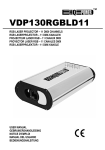
1
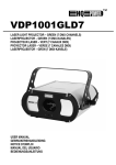
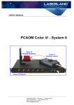
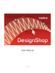
Laser Projector Manual
Laser Show Software
Laser Projector Manual
Nov. 2005
1、
、Laser Projector Introduction:
Laser Projector is a Laser show software. It contains three pieces
related and separated programs. They are graphics drawing and compiling
project: Drawing Tool, compiling project of show effect: Designing Tool.
The third part is used to reorder the shows in the flash disk.
2、
、 Installation of LaserProjector
Insert CD disk into CD-ROM,click on “Setup” icon, it will process the
software installation.
3、
、 Drawing Tool
I.
Drawing Tool Summarization
Drawing Tool is mainly used to draw and compile the graphics. After
edition, it will be saved with the extension name as “.LPD” . There are
several frame figures in one piece of LPD program and 3000 points in per
frame figure.
Drawing Tool can not only deal with LPD figure, but also can deal
with .ILD figure using “Open”, so do the .DXF figure using “Import”.
During import process, program will convert the above figure into the
figure format that is suitable for Laser show.
Drawing Tool also provide the function of direct input letters.
II. Drawing Tool’s Menu
Drawing Tool has six item: File 、Edit、Draw、Setting、About and
Page 1 of 11
Help.
Menu of “File”
File contains:New File、New Frame、Open File、Input File、
Save As、Frame Save and Exit.
New File: building a new graphic file with the extension
name “.lpd”, and clean out all the real-time graphic
information in the screen. If the editing graphic has not been
saved, system will mind you to save it or not.
New Frame:It means add one frame to the last part of
editing LPD file.
Open File:It will pop up a dialog box of “Open File”, and
can open LPD file and ILD file. After opening the file, the
graphic of current frame will appears in drawing box,
meanwhile the frame number appears in the select box of
current frame. The frame number begins from 0.
Import File:Like the opening file, pop up a dialog box,
you can select DXF file. DXF file is according to DXF
format of AUTO CAD2000 , supports drawing line,
multilane, circle, arc, ellipse, rectangle, polygon, curve and
etc in CAD, does not support input letters directly in CAD.
User can use the letter-input function of this software to do
letter-input if needed.
Save as:Save the current editing LPD file into another LPD
file.
Save frame:Save the current editing graphic into the current
frame which is displayed in the current frame selecting
box。If you are editing an unnamed graphic file, or an
opening ILD file, or an input DXF file, there will pop up a
saving dialog box, requests you name this file.
Laser Projector Manual
Exit:Quit from Drawing Tool.
Edit Menu
Edit Menu provides the function of editing graphic in the
drawing box, such as: Move, Rotation, Zoom, Flip Horizontal,
Flip Vertical, Center, Point Edit, Cancel, Copy, Cut, Plaster,
Delete, and Eliminate jump.
Move:The cursor in the drawing box will change into
Page 2 of 11
down, the vertical dimension will be prolonged, contrarily,
will be shrunk.
Flip horizontal : Make the graphic turning around the
horizontal axis, forming an image.
Vertical turn:Make the graphic turning around the vertical
axis, forming an image.
Center: Make the graphic to be symmetrical to the center
of drawing box.
.If you drag the mouse in the drawing box now, the
graphic in the drawing box will move following the mouse.
Rotation:The cursor changes into
,meanwhile there will
appear a rotation select box on the left side of graphic
box:
Fig.7
It can make the graphic turning around the center point via
changing the” rotating angle” in the select box. You also can
adapt the turning center according to the requirement, just
adjust the data in the “X center” and “Y center” in the edit
box.
Zoom: When the cursor in the plot box changes into
.
Drag the mouse in the drawing box to change the dimension
of the graphic. You can drag the mouse towards left to
prolong the horizontal dimension, contrarily, to shrink the
horizontal dimension. When you drag the mouse towards
Point edit:Cursor changes into
. Use the cursor to
select one point in drawing box, and then drag the mouse to
change the coordinate position of this point.
Cancel:cancel the last editing.
Copy: copy part of graphic in select box to cut board. If
does not use the select box, it will select the whole frame in
the plot box.
Cut: cut part of graphic in select box to cut board. If does
not use the select box, it will select the whole frame in the
plot box.
Plaster:Paste the content of the cut board to the plot box.
Delete:delete the graphic in the select box. You should use
the select box to select the content which you want to
delete.
Eliminate jump:When editing the neighbor break spot of
the current graphic, if the space is to broad, it will insert
some “dark spot “ to make the output better.
Drawing Menu
Drawing Menu provides the drawing means as following:Spot
drawing, Line drawing, Ellipse drawing, rectangle drawing and
Laser Projector Manual
Character input and rolling letter output.
Point drawing:After select the function of point drawing,
click the mouse in the drawing box, and you can get one
point. Considering the display requirement, there will be
several invisible “dark point” except one visible “bright
point” in this position.
Line:Select the Line function, click the mouse in drawing
box to determine the beginning of the line, then drag the
mouse to the end point. Release the mouse key, and finished
line drawing.
Ellipse:After selecting the function of drawing ellipse, click
the mouse to determine the center of the circle, drag the
mouse to determine the long axis and short axis, then
release the mouse key to finish the ellipse drawing.
Rectangle:After selecting the function of drawing rectangle,
click the mouse in plot box to determine one corner of
rectangle, then drag the mouse to the position of another
corner, release the mouse key to finish the rectangle
drawing.
Text:After you selecting the function of Character, it will
pop up a letter inputting box,(Fig.8):
You can select letterform, style(size) of the letter, then click
“Input Text” dialog box to input the letters. If you want to
modify the font or size, you can change the data in relative
edit box, do not need input the letters again. After letter
input, press “Enter” key to quit.
Page 3 of 11
Fig.8
rolling letter: after selected this item, there will be an
interface as Fig.9.
Laser Projector Manual
Page 4 of 11
e)
Fig.9
Items “Select style”, “Select type” and “Letter input” are same as
those in the interface of “Text”. The differences are::
a) Input more letters( allow overstep display box, use the scroll
bar to view all the contents).
b) Define the letters inputted. Drag the mouse in the display
box to set area of editing, the part selected will change to
purple. Then choose the color you wanted in the Color Box,
click the mouse, the selected area changes to wanted color.
c) Press the key of outputting, The letters move into the
displaying box from right side gradually, until move out by
the left side.
d) If select “Flash Data”, when click the key of “output”, the
contents of scrolling letters in displaying box will be created
and saved as an UPD file.
The content edited in this interface can’t be transferred to
main interface for editing.
Setting Menu
Setting Menu is mainly providing some data of drawing. When
select this menu, it will pop up a window as following:
Fig.10
“Setting Step”is to determine the distance between points.
“Line ends Points”is to determine the quantity of assistant
points inserted in order to keep the integrality of displaying when
you draw a line.
“Corner Points”is to add some points in order to not display the
corner like an arc during drawing.
“Ratio of Circle” is to make sure the integrity of circle ,
exceed 360 ° when drawing arc. The data displays the
percentage of arc drawing to 360°.
Laser Projector Manual
“Scan speed” defines the scanning frequency of scanner when
outputting graphics. The unit is 1000PPS(1000points per
second for M), selecting range is 8K~24K(8,000PPS~
24,000PPS).
“Blanking Points”is the assistant point to match the Scanner
and Laser modulating speed. When graphic displayed appears
drag line on the point of laser switch , you should increase the
value;If it appears brighter points than other points, you
should decrease this value.
“Shift Points”is the assistant for matching Scanner and Laser
Modulating Speed.
“Laser Type”is let the user to choose which type of Laser to use
according to matching this software, to insure it can display the
graphic drawing integrally no matter when using single or double
color laser.
“Load Default”is to load the original value as your setting
parameter.
“Language selection” is used for selecting the language
displayed for program. Chinese and English are available for
selecting.
Page 5 of 11
leading to scanner’s damage directly.
III. Shortcut Key
For convenient use, there are several shortcut key .You just click such
key conveniently to finish some functions.
Function as “New Frame” in “ File Menu”.
Function as “New file” in “ File Menu”.
Function as “Open File” in “File Menu”.
Function as “Input File” in “File Menu”.
Function as “Save frame” in “File Menu”.
Function as “Save as” in “File Menu”.
Function as “Cancel” in “Edit Menu”.
Function as “Copy” in “Edit Menu”.
Notice:
Unless in special circumstances, the value item in
“step setting” should not be defined more than 100. If you need
larger step when using, please select a smaller value for
“scanning speed”. For example, set scanning speed to 12. Larger
step, higher scanning frequency, the electric current of scan
machine will be larger. Long time working with large current
will affect the lifetime of scan machine greatly. If set step too
larger in circumstance of high scanning speed, it is possible
Function as “Cut” in “Edit Menu”.
Function as “Plaster” in “Edit Menu”.
If select this function, click the mouse in drawing box, there will
be a dot on the position of the mouse, meanwhile serial number is
behind this dot.
Laser Projector Manual
Page 6 of 11
Function as “Delete” in “Edit Menu”.
Function as “Ellipse” in “Drawing Menu”.
Function as “Move” in “Edit Menu”.
Function as “Drawing point” in “Drawing Menu”.
Function as “Rotation” in “Edit Menu”.
Function as “Character” in “Drawing Menu”.
Function as “Zoom” in “Edit Menu”.
Function as “Edit Spot” in “Edit Menu”.
IV. Status Box
Include:Plot Status box、Color Status box and Current Point Status
box.
Plot Status box
Function as “Flip Vertical” in “Edit Menu”.
Function as “Flip Horizontal” in “Edit Menu”.
Function as “Center” in “Edit Menu”.
This is a select box. Select this function, click the mouse in
drawing box to decide one end,then drag the mouse to decide
another end, release the mouse , all the points in this area are
selected. The following editing, such as Move, Rotation etc. are
just effected to the point in this select box. But after one being
edited, the Selection is unavailable , you should repeat above
operation to edit points in drawing box.
Fig.11
“Points”denotes the point number of editing graphics in current
drawing box.
“Cursor”denotes coordinate of mouse in current drawing box.
Palette
Function as “Line” in “Drawing Menu”.
Function as “Rectangle” in “Drawing Menu”.
Fig.12
Click the mouse to select color, the color in below rectangle
Laser Projector Manual
shows the current color you select.
Current Point Status box
Page 7 of 11
time unit, display program display effect effect box
edit time
Fig.13
“No.”is the sequence number of current point.
“X”
、
“Y”are the X、Y axis coordinate value of current point.
“Color”is the color of current point.
4、
、 Designing Tool
I. Designing Tool Summarization
Designing Tool is used to do effect edition of graphics, and arrange the
effects according to your expectation, make them to be a series of effects.
When using Designing Tool to edit effects, the effect can be applied to one
frame graphics,also can be applied to a series of bordering graphics. Each piece
of effect can be endowed with three kinds of transforming status at best.
Designing Tool can output three different effects in one time, so
combination of different effect enrich the output impact.
II. Interface of Designing Tool
graphics list
graphics list scroll bar
Fig.14
There are three effect-editing items in effect-editing box. Contents in
different effect-editing box can be displayed, like three path to output data.
III. Main Menu of Designing Tool
Main Menu of Designing Tool contains :File 、Setting、About and Help.
File Menu:
File Menu contains :New Show、Open Show 、Save Show 、Save
as and Exit. Their objects are editing effect files.
New Show:To build one new effect file, at the same time, weed
out all the contents which are in the effect editing box and
graphics list, reset the time to zero.
Laser Projector Manual
Open Show:Pop up a dialog box of open file, select the effect
file for editing (expansion name is “.SHO”). After close the
dialog box, the effect list and graphics will be displayed in effect
edit box and graphics list. The color block in edit box show
different effect, and its position denotes the start time, and its
length denotes the displaying time. Start and end time and
corresponding graphics frame number are displayed in the color
block. When move the mouse to one effect color block, click the
right key of mouse the start and end time and sustaining time will
be displayed in status bar.
Fig.15
Save Show:Save the current editing effect file.
Save as:Save the current editing effect file with another name.
Exit:Exit from the file’s performance.
Setting Menu
Please refer to Menu Setting of Drawing Tool.
Page 8 of 11
About Menu
Please refer to About Menu of Drawing Tool.
IV. Pop-up Menu of Designing Tool
Click the right key of mouse in graphics file list, the pop-up menu will
display. Pop-up Menu of Designing Tool contains:Open graphics file and
Mark, and Mark has three subsidiary item: Marking Start、Marking end
and Cancel marking.
Open file:
:There will pop up a dialog box,you should select a
graphics file. Graphics file can be LPD file or ILD file. The graphics
you opened will be displayed in graphics list. If the graphics frame
exceeds 30 pieces, you can use the scroll bar on right to select the
graphics which is at back.
Mark:
:If you want do an effect with a series of graphics, you should
mark the graphics first. First of all, you should select the marking
Start in outspread item, then select the first frame you needed by
click the left key of mouse. Click the right key again, select the item
Marking End, then select the last frame by click left key. Now, from
first frame to last frame, all the frame number box above the graphics
will be changed to yellow, it means be selected. If you want to
reselect, you can use Cancel mark. Using this function can make the
frame number got back to the original color. This means mark being
canceled.
V. Effect Edition
Effect Edition contains several steps as following: Select graphics、
Set starting time and displaying time of effect、edit effect content.
Select graphics:Though clicking left key of mouse on one frame in
graphics list or adopting marking method to select a set of graphics.
Set starting time and displaying time of effect:Click left key of
mouse in selected graphics box, drag it into file editing box, then
Laser Projector Manual
Page 9 of 11
release the key. There will be one vertical red line, corresponding
time and selected graphics frame will be displayed in time list. You
also can drag this red line to left or right to determine the starting
time for this effect (but can not exceed edited effect on the left or
right), or drag by right key, here red line becomes to a color block
box, and its length denote displaying time (neither exceed edited
effect on the left or right).
Edit effect content:After select graphics and set time, one piece of
effect is established. But here the effect of graphics is static when
displaying. If you want to make a carton composed by a set of
graphics, you have finished effect making. If you want to make a
dynamic transformation of graphics, you also need to do effect
editing. First you need to confirm the effect which you want to edit,
then click the this effect block, change the color lick
,
and then according to the editing bar, click the “edit” button on the
left of editing bar. So come to effect editing interface.
Choose transformation mode: Effect edit interface contains:
“move”、 “writing”、 “Rot X”、 “Rot Y”、 “Rot Z” and “ZOOM”
totally six effect combo boxes and one “Selected” list. If you want
to add a transformation mode to editing effect, you can click the
left key in corresponding combo box, then drag the mouse and
place it in the blank of “ selected” list (The content will be replaced
if there is content before).
Set transformation parameter: You also need to set the
transformation parameter, such as the starting and ending position
of “move”, and starting angle, ending angle and turning center in
turn mode.
Fig.16
Angle and Scale:Here we want to have YOUR ATTENTION
that angle in rotation mode is the percentage to 360°, such as
90°is 25、180°is 50, but zoom scale is proportion to original
dimension of graphics.
Transformation center:You can select different transformation
center when rotating and zooming, graphics rotating or
zooming around different axis makes different effects.
Writing mode: “ Erase” option in Writing mode is to display
completed content first, then remove the graphics gradually in
the light of point order number of graphics.
Repeat time : There is “repeat time” option is every
transformation combo box. It means transformation repeat
times within this effect displaying period.
Laser Projector Manual
Preview: Graphics of this effect is displayed in preview box,
there are “Start status” and “End Status” options above it. Via
this option, you can see the effect starting state and effect
ending state separately, for the several effects outputting at the
same time, you can get the effect cooperation of several
effects.
Pre-play:After finished transformation mode selecting and
parameter setting, if you want to know the effect of your
design, you can click “Preview” key. The pre-play box will
display the transformation of editing effect. In order to obverse
the combination state of several effects, the program will
display together with current editing effects at the same time
automatically when pre-playing.
Real-time display:If you want to look into the effect of laser
outputting when pre-playing, just connect the control card
which is matched with Laser Projector,and select the “USB
output” option which is beneath preview box, then the
synchronous content of pre-play will be inputted into your
Laser display equipment.
Exit editing:Click the “confirm” or “ Cancel” button to quit
from effect editing interface. If you clicked “confirm” button,
the content will be saved, and transformation mode you
selected for this effect will be displayed in “current effect” of
main interface.
Page 10 of 11
box. If select “ USB output ” in select box, content displayed will be
outputted via USB port, if select “ Create data”, when displaying ,the
program will auto-create one file for flash disk, the file has the same
name as the graphics file , but with the extension name “.UPD”.
Repeat key:
If this key is pressed down, the program
will repeat displaying contents;if this key is pressed up, the program
will auto-stop displaying after playing the contents of scheduled
time.
Time display box:
This box will display the
real time of the current displaying program.
VI. Play
Via clicking “whole display” or “effect display” button to play all effects
or current selected effects. Interface of Play is as following.(Fig.17)
Play key:
Click this key to play the program in display
Fig.17
Laser Projector Manual
Page 11 of 11
5、
、 Writing to Flash Disk
It is required that the flash disk is formatted in FAT. It does not support
NTFS and other format. You should create a directory ‘UPD’ in the flash
disk. Then you can copy the UPD files, which you want display in the laser
projector, to the directory.
You plug the flash disk including the ‘upd’ files into the USB port of
the laser projector and turn on the projector. You can see the laser shows.
If you want to output the ‘upd’ files in sequence, You can realize the
target in two ways:
You can delete all the files in the ‘upd’ files of the flash disk. Then
you copy the ‘upd’ files one by one according the sequence you
want.
You can you the program ‘Reorder’ to adjust the sequence of the
‘upd’ files in the flash disk. After you plug the flash disk into the
USB port of your computer and start the ‘Reorder’, you can the
screen like following. You select the files which you want to
change the position and you ‘Up’ key or ‘Down’ key to move the
files to the desired position. Then you can click the ‘Reorder’ to
write the new sequence into the flash disk.
Fig. 18