1
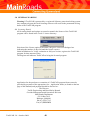
15th October 2008
TraSiCAD v 2.8
Instruction Manual
Contact Information
Name:Tom Vucetic
Address :- 477 Boundary St. Spring Hill
Brisbane 4001
Phone:07 38347315
Fax:07 38342201
Email:- [email protected]
TraSiCAD 2.8 – October 2008
2
CHAPTER 1
CONTENTS
INTRODUCTION TO THE MANUAL
SECTION 1
1.1
CHAPTER 2
ABOUT THIS USER MANUAL
Purpose of this manual
USING TRASICAD
………………….
5
…………………. 6
…………………. 6
………………….
7
SECTION 2.1
What is TraSiCAD ?
………………….
8
SECTION 2.2
INSTALLING TraSiCAD
………………….
9
SECTION 2.3
OPENING TraSiCAD
………………….
10
SECTION 2.4
2.4.1
2.4.1.1
2.4.1.2
2.4.1.3
2.4.1.4
SETTING UP DEFAULTS AND OPTIONS
Options
General
Edit
New signs
Display
………………….
………………….
………………….
………………….
………………….
………………….
10
10
10
11
11
11
SECTION 2.5
2.5.1
2.5.2
2.5.3
2.5.4
STARTING A DRAWING
New
Open
Use Wizard
History Bar
………………….
………………….
………………….
………………….
………………….
12
12
12
13
13
SECTION 2.6
2.6.1
2.6.1.1
2.6.1.2
2.6.1.3
2.6.1.4
2.6.1.5
2.6.1.6
2.6.1.7
2.6.1.8
2.6.1.9
2.6.1.10
2.6.2
2.6.3
2.6.4
2.6.5
2.6.6
2.6.7
2.6.8
2.6.9
DRAWING OPTIONS
Functions
Undo
Redo
Add
Align
Adjust
Copy
Cut
Paste
Paste special
Delete
Adding a Legend
Adding a Road Name Patch
Adding a Route Marker
Adding an Other Sub-Sign
Adding an image
Adding an Arrow
Adding a Roundabout Symbol
Adding a Diagrammatic Direction Symbol
………………….
………………….
………………….
………………….
………………….
………………….
………………….
………………….
………………….
………………….
………………….
………………….
………………….
………………….
………………….
………………….
………………….
………………….
………………….
………………….
14
14
14
14
14
15
16
17
17
17
17
17
18
18
19
19
20
21
22
24
TraSiCAD 2.8 – October 2008
3
CONTENTS cont.
SECTION
SECTION
SECTION
2.7
VIEWING OPTIONS
………………….
26
2.7.1
2.7.2
2.7.2.1
2.7.2.2
2.7.3
2.7.4
2.7.4.1
2.7.4.2
2.7.4.3
2.7.4.4
2.7.4.5
2.7.4.6
Zoom
Gridlines Setup
Show Grid
Snap to Grid
Dimensions
Sign Properties
Panels tab
Legends tab
Images tab
Guide Symbols tab
Signs & Sub- Signs tab
Multi Panel Border and Colour control
………………….
………………….
………………….
………………….
………………….
………………….
………………….
………………….
………………….
………………….
………………….
………………….
26
26
27
27
27
28
28
29
29
29
30
31
2.8
SAVING A DRAWING
………………….
33
2.8.1
2.8.2
2.8.3
Save As
Save
Export
………………….
………………….
………………….
33
33
33
2.9
PRINTING
………………….
34
2.9.1
2.9.2
2.9.2.1
2.9.2.2
2.9.2.2
2.9.3
2.9.4
2.9.5
2.9.5.1
2.9.5.2
2.9.5.3
2.10
Printer Setup
Page Setup
Layout tab
Title Block tab
Margins tab
Print Preview
Print
Sign Object Viewer
Create List
Save as Text
Print List
Closing a Drawing
………………….
………………….
………………….
………………….
………………….
………………….
………………….
………………….
………………….
………………….
………………….
………………….
34
34
34
35
35
36
37
37
37
37
37
38
General warning
Licensing Details
Extension of License
Transfer of License
………………….
………………….
………………….
………………….
………………….
39
40
40
41
41
Sample Sign G1-4 drawing print out (no dimensions)
Sample Sign G1-4 drawing print out (dimensions)
G1-4 Route marker print out
G1-4 Road Name Plate print out
G1-4 Arrow symbols print out
Order Form
………………….
………………….
………………….
………………….
………………….
………………….
………………….
42
43
44
45
46
47
48
CHAPTER 3
LICENSING
3.0
3.1
3.2
3.3
Appendix A
TraSiCAD 2.8 – October 2008
4
CHAPTER 1
INTRODUCTION TO THE MANUAL
TraSiCAD 2.8 – October 2008
5
Section 1
About This User Manual
1.1
The Purpose of this Manual
Audience
This User Manual is intended for designers utilising the TraSiCAD
software program for the design of signs.
Scope
The User Manual describes the process involved to
• Create new signs with in Standard guidelines
• Produce designs for manufacture
• Interpret messages, warnings and errors
Reader Skills
The User Manual assumes that the reader has a basic knowledge of:
•
•
Personal computers
Australian Standards relating to Road sign Specifications (AS1743)
Expected Outcomes
After studying this manual, the reader should be able to
• Create new signs
• Understand sign clearances
• Print drawings
• Interpret messages, warnings and errors
TraSiCAD 2.8 – October 2008
6
CHAPTER 2
USING TRASICAD
TraSiCAD 2.8 – October 2008
7
Section 2
2.1
WHAT IS TRASICAD ?
TraSiCAD V2.8 is a program developed by Traffic Engineering and Road Safety Branch, a
division of Main Roads to assist in the design of road signs.
This user manual is intended to be used in conjunction with:Australian Standards AS 1743 Road signs – Specifications
Australian Standard AS1744 Standard Alphabet for road signs
Australian Standard AS1742 Local Area Traffic Management
Manual of Uniform Traffic Control Devices (MUTCD)
More information can be found on the Queensland Main Roads Department web site at
www.mainroads.qld.gov.au
For TraSiCAD V2.8 downloads search on "TRASICAD"
TraSiCAD 2.8 – October 2008
8
2.2
INSTALLING TraSiCAD
•
BY CD
Insert the TraSiCAD installation CD.
Select Run on the Windows desktop
Browse the CD drive
Select Install TraSiCAD V2.8
TraSiCAD will automatically set up all files.
Follow all prompts till completed, then select Finish
•
BY DOWNLOAD FILE
Go to Main Roads web site (www.mainroads.qld.gov.au)
• In the search bar search for TRASICAD. Find the relevant download
• Save to a relevant PC directory
• Select and run the Install file
TraSiCAD will automatically set up all files.
Follow all prompts till completed, then select Finish
TraSiCAD 2.8 – October 2008
9
2.3
OPENING TraSiCAD
After installation has been completed, open the program by
either:1. Running from the executable file in the directory in
which the program was installed.
or
2. Double click on the TraSiCAD icon developed on the
computer desktop during the installation.
The TraSiCAD working screen will appear showing options
directories to be used in TraSiCAD design.
Note
TraSiCAD has its own complete Help function that may
be utilised in conjunction with this user manual.
2.4
SETTING UP DEFAULTS AND OPTIONS
TraSiCAD can set various default options required during the drawing design process.
Before using TraSiCAD the various options can be set up with default characteristics.
For faster and more efficient use of the program these options should be set prior to the
commencement of any design.
2.4.1 Options
From the Tools directory select Options.
This opens a dialogue box with 4 tab functions.
2.4.1.1 General
• Gives the option of selecting parameters with
particular RTA characteristics.
• Accesses the clearance Rule Set that determines the
particular clearance rules for the elements within
the sign. A new rule set* is determined at
Supervisor level by a separate Rule Generator.
• Sets the order in which clearances are made.
• Allows automatic setting of Borders and corner radii when clearing, if required.
• Redirects the default sign saving directory to user defined, if required.
* These Rule sets have been based on the AS 1743 standards and should not be modified unless there are valid design reasons.
Because they are permanently editable, care should be taken in any modification process. It is advised to keep a Master copy
of these rules or create a new working Rule set through the New option.
TraSiCAD 2.8 – October 2008
10
2.4.1.2 Edit
• Varies the nudge distance of elements on the sign face.
Using the UP/DOWN/LEFT/RIGHT arrows on the keyboard,
fine control of element placement can be achieved.
• Allows selection of copying file types
• Selects the number of Undo functions available.
• Can decide if the undo / redo stack is reset or not after a
save function has been completed.
(1) Default legend
2.4.1.3 New Signs
• Sets the Default Legend height. This height sets
clearances in association with the current rule set
being used.
• Enables the setting of default legend for the various
signs and route markers, which are utilised in
conjunction with the various wizards.
TO BE COMPLETED PRIOR TO USE OF TraSiCAD.
•
•
•
•
•
•
(2) Default Print Settings
Selects ability to show arrow heads in dimensions
Selects the default printing scales.
Sets the default print margins.
Sets the default font for the print title block.
(3) Default Title Block Settings
Sets default Business Unit Details
Loads/deletes a pre designed logo as a default for use in
the print title block.
2.4.1.4 Display
Sets the colouring characteristics of TraSiCad when non-system colours are displayed and represented.
When using a display device with a colour palette smaller than 24
bits, some colours will not be available in the device palette and
will need to be approximated. Two methods are available:
• Closest Match - Colours are represented by the closest
matching colour from the logical palette of the display
device.
• Dithering - Colours are represented by drawing a pattern
using similar colours.
TraSiCAD 2.8 – October 2008
11
2.5
STARTING A DRAWING
There are 4 different methods of accessing drawings within the TraSiCAD program.
Selecting the File directory indicates New, Open, Wizard or the file history bar.
Note:- Once a drawing has been commenced, it is recommended that the Sign Properties
Feature (Alt+P) is utilised to enable user nominated variables to be entered. (see 2.7.4)
2.5.1
New - Used to develop new signs utilising basic styles and backgrounds. There are up to 16
different styles that are selectable from this box.
2.5.2
Open –Used to open a previously designed sign
from a file directory. This option can be used to
modify, copy or print previously designed signs
selected from the user’s specific local or network
files and directories. (see 2.4.1.1)
or
Can be used to access the specific Signs directory
within TraSiCAD.
This directory contains a number of signs.
TraSiCAD 2.8 – October 2008
12
2.5.3
Use Wizard - Used to select a particular type of sign from a list of wizards (RTA selection if
needed. See 2.4.1.1). This gives a specific design of a sign which will be set out
according to predetermined standard format and style.
Wizard selection process
•
RTA selection
Main Roads selection
Select required Wizard
(Dependant on which installation is used (RTA or
MR) an example window indicates the type of sign
to be selected.)
•
Select number of panels (if available) the
particular Legend Type and Height.
Note:- The legend value selected here only
assigns the characteristics for the legends on
that sign. They have NO bearing on the Default
legend height value that set the clearance values
between the elements on that sign.
•
For each of the panels requested in the previous step, select and
apply details for a
Road Name Patch,
Route Marker type and number,
Arrow type and
Legend
Note :- To assist with drawing efficiency, the subsequent use of any wizard allows the user
to utilise previously entered values of a wizard when it was last run.
For example if a three panelled wizard design was initially
utilised and there was a requirement for a subsequent two
panelled sign, then any of the legends or symbols from the first
two panels may be selected for use in that new design
2.5.4
History Bar - Used to select up to ten previously
worked on drawings with out the need to close off the
current drawing.
TraSiCAD 2.8 – October 2008
13
2.6
2.6.1
DRAWING OPTIONS
Functions
Modifications, additions and adjustments can be made to any sign drawing utilising the Edit
directory on the tool bar.
The functions dialogue box gives access to options which include :•
Undo
•
Redo
•
Add
•
Align
•
Adjust
•
Copy
•
Cut
•
Paste
•
Paste Special
•
Delete
Selection from this list in the Edit directory or using the associated short cut keys will utilise
the functions as follows:-
2.6.1.1
Undo
Undoes the last number of drawing steps carried out. (Undo levels are set in Tools
directory under Options / Edit.) (see 2.4.1.2)
2.6.1.2
Redo
Redoes the previous Undo functions. Redo’s are limited by the amount of undo levels.
2.6.1.3
Add
Facilitates the addition of various items to be inserted in a drawing.
Consisting of :•
Legends
•
Road Name patches,
•
Route markers
•
Sub Signs
•
Images from file (see 2.6.2)
•
Arrows (see 2.6.3)
•
Roundabout signs (see 2.6.4) and
•
Diagrammatic Direction Symbols
(see 2.6.5).
TraSiCAD 2.8 – October 2008
14
2.6.1.4
Align
This function allows for the horizontal or vertical alignment of two or more separate
items on a drawing.
Note:- All preselected items will aligned to the LAST item selected in the Align process.
Alignment of two single items
1. Select the first item requiring to be aligned to a another.
2. Hold down the shift key and select the second item.
3. Select Edit directory then Align (or Ctrl L). An
Alignment Tool dialogue box will appear.
4. Select the relevant Horizontal (Top, Centre or
Bottom) or Vertical (Left, Centre or Right) alignment
box.
5. The items will appear aligned on the screen.
6. Select OK.
7. The sign will be permanently aligned and updated in the drawing.
Vertical alignment of multiple legends (eg.Rest Area & 1km)
Quantity items may be made up of two separate “words” (eg. “1” &” km”).
To correctly align these separated quantity items
with other legends :1. Select the number “1”
2. Hold the shift key then select “km”
3. While still holding the shift key select the legend “Rest Area” to
which the quantity item is to be aligned.
4. Select Edit directory then Align (Ctrl L) where an Alignment Tool
dialogue box will appear.
5. Select the Group Into Rows box.
TraSiCAD 2.8 – October 2008
15
This will group select the “1” and the “km.”
This will be indicated on the screen with
dotted box enclosing both items selected.
6. Select Centre for a centre alignment.
A position measurement indicator
will appear signifying the centre
position of the new alignment line.
Manual modifications to this position
measurement can be made in this
box if required by direct editing or
using the up / down arrows.
7. Select OK to generate the newly aligned sign.
2.6.1.5
•
Adjust
Sets the automatic adjustment of items on the sign face at predetermined clearances.
Two separate options are available.
Apply Clearance Rules
Enforces an automatic clearance on
all items on the drawing to give
predetermined spacings from rules
installed within TraSiCAD. These
rules can be found in the Rule Editor
in the Options directory. (see 2.4.1.1
SETTING UP DEFAULTS AND OPTIONS ).
Note:Note:
Clearances
are determined
by the “Default
legend” size
and not
Clearances
are determined
by the “Default
legend”
size the
which may
size
of
the
legend
being
utilised
on
the
drawing.
NOT be the size of the legend being utilised on the drawing.
TraSiCAD 2.8 – October 2008
16
•
Reduce Sign
This option completely reduces the sign to its smallest
size, taking into consideration and applying clearance
rules formulated in the Rule Sets previously mentioned in
2.4.1.1.
It will set the borders and corner radii to the appropriate
values if the particular request boxes are checked in the
Options / General dialogue box.(2.4.1.1.)
2.6.1.6
Copy
Takes a copy of the selected item on the drawing and places it on a working clipboard
to be reutilised on that drawing or in other compatible software applications.
The copied item remains intact on the drawing.
2.6.1.7
Cut
Takes a copy of the selected item before erasing it from the drawing. It places it on a
working clipboard to be reutilised on that drawing or in other compatible software
applications. This function can also be used as a delete.
Note that the working clipboard will only hold one item at a time. If
another object is subsequently cut or copied the previous object will
me overwritten, depending on the number of undo levels.
2.6.1.8
Paste
Places the object obtained by the last Cut or Copy function, from the working clipboard
onto the present working drawing.
2.6.1.9
Paste Special
Enables two separate ways to import items from the Clipboard of other Windows
applications.
• Paste Text as a Legend
Takes text copied or cut to the “Clipboard” from other compatible applications and places it on
the working drawing in a "Text Editable" format.
• Paste Metafile as Image
Imports an object or text copied or cut to the “Clipboard” from other compatible applications
and places it on the working drawing in a NON editable form. This is ideal for quickly
importing logos and symbols from electronic brochures.
2.6.1.10 Delete
Deletes any object from the drawing. The option does not utilise the working clipboard
and therefore the object will be deleted permanently. The Undo function will undelete
any object deleted dependant on the amount of undo levels set in the Options \ Edit box
(see 2.4.1.2)
TraSiCAD 2.8 – October 2008
17
2.6.2
Adding a Legend
Note. The Add function can be activated in a shortcut mode by placing the cursor
somewhere on the active drawing and right clicking the mouse. A dialogue box with four
options, including Add, will appear on the drawing.
Selecting legend allows specified words to be
imported into the drawing from the ensuing “Add to
Panel” dialogue box.
Particular Legend types and heights can be selected as
required. Note that all fonts used in TraSiCAD are
derived from the C:\Windows\Fonts directory. All
Australian Standard Highway fonts (sold separately to
this software) should be installed there.
2.6.3
Adding a Road Name Patch
Note. The Add function can be activated in a shortcut mode by placing the cursor
somewhere on the active drawing and right clicking the mouse. A dialogue box with four
options, including Add, will appear on the drawing.
Selecting Road Name Patch allows one of the
following a specified shaped patches to be imported
into the drawing from the ensuing “Add to Panel”
dialogue box.
•
•
•
•
Not Pointed
Left Pointed
Right Pointed
Double pointed
TraSiCAD 2.8 – October 2008
Note that the legend height used
in a Road Name patch is
automatically reduced to 75%
of the main sign legend height.
18
2.6.4
Adding a Route marker
Note. The Add function can be activated in a shortcut mode by placing the cursor
somewhere on the active drawing and right clicking the mouse. A dialogue box with four
options, including Add, will appear on the drawing
Selecting Route Marker allows one of six different
types of markers to be imported into the drawing
from the ensuing “Add to Panel” dialogue box.
•
•
•
•
•
•
2.6.5
Alpha-numeric Route markers
Tourist Route markers
State Route markers
Metroad Route markers
National Highway Route markers
National Route markers
Adding an Other Sub- Sign
Note. The Add function can be activated in a shortcut mode by placing the cursor
somewhere on the active drawing and right clicking the mouse. A dialogue box with four
options, including Add, will appear on the drawing
Selecting Other Sub-sign allows selection of all
types of signs to be imported onto the main sign
from the ensuing “Add to Panel” dialogue box.
TraSiCAD 2.8 – October 2008
19
2.6.6
Adding an Image
Note. The Add function can be activated in a shortcut mode by placing the cursor
somewhere on the active drawing and right clicking the mouse. A dialogue box with four
options, including Add, will appear on the drawing.
Selecting Image From File allows special image
files to be imported into the drawing from the
ensuing “Add to Panel” dialogue box.
TraSiCAD has access to an internal directory of .wmf symbol files that can be directly
imported into the drawing.
Selecting add an Image From File will
usually directly access the Symbols library
within the TraSiCAD program.
In a typical install this file location will be
C:\Program files\MainRoads\TraSicad\Symbols
Note: TraSiCAD allows the importation of any .emf or .wmf files. If other self generated
symbols files are designed they may be placed in this directory for convenience or located
in other directory locations to be “browsed” for.
Select the required symbol.
Select Open
An “Add Image” dialogue box will appear indicating the symbol selected. The height and
width are shown along with a scaling option to increase or reduce the importing size.
Options can then be made to accept, change
(reverts to previous dialogue box for another
selection) or cancelling the symbol.
TraSiCAD 2.8 – October 2008
20
2.6.7
Adding an Arrow symbol
Note. The Add function can be activated in a shortcut mode by placing the cursor somewhere on
the active drawing and right clicking the mouse. A dialogue box with four options, including Add,
will appear on the drawing.
Various types and sizes of arrows can be added to
a sign by selection of the Arrow Symbol from the
“Add to Panel” dialogue box.
Various types and sizes of arrows can be designed and modified from the “Add New Arrow Symbol”
dialogue box.
Through various individual boxes the
actual size of the arrow based on a
particular legend height can be established
along with,
•
•
•
•
•
•
•
•
Widths,
Lengths,
Shaft lengths,
Base widths,
Arrow head heights,
Arrow indents,
Corner radius and
Rotation angles
Other functions to determine colours,
rounded or pointed arrowheads and
standardised long or short length shafts
can be made in this option.
Note: Double clicking on any colour
brings up a full colour pallet
A zoom function is also available to enhance the details in the design box.
Note: this does not affect the zoom in the actual drawing
TraSiCAD 2.8 – October 2008
21
2.6.8
Adding a Roundabout Symbol
Note. The Add function can be activated in a shortcut mode by placing the cursor somewhere on
the active drawing and right clicking the mouse. A dialogue box with four options, including Add,
will appear on the drawing
Various types and sizes of roundabouts can be
added to a sign by selection of the Roundabout
Symbol from the "Add to Panel" dialogue box.
Various types and sizes of Roundabouts can be designed in the ensuing “Add New Roundabout”
dialogue box. Three sections are can be accessed through various boxes in each, where a number of
options for specific designs can be entered.
•
View section
r1 Inner roundabout radius
r2 Outer roundabout radius,
a Views, sets and changes the value,
in mm, of the height of the
triangular tip of the exit leg.
c Width of the exit legs.
g Location in degrees of the gap.
h Width of the arc gap in degrees.
Roundabout colour Sets the symbol colour.
Note: Double clicking on any colour brings up a full colour pallet
Legend height
Sets the overall size of the symbol
Arc Gap Style
Sets a Square ended exit, a Pointed end on the exit or a Double Point that gives a
pointed entry and exit.
Rotation Angle
Sets the rotation angle (in degrees) of the symbol.
Zoom
Sets screen viewing for better design detail.
TraSiCAD 2.8 – October 2008
22
•
Exit Legs Section
Exit legs may be straight or curved. By checking the Curved box, two options become available.
Curved left
and
Attached at Base
Sets the exits to curve clockwise as opposed to the default anticlockwise.
Determines if the arc of a curved leg should be tangential to the roundabout
body or tangential to centreline of the triangular tip of that leg.
Other options:Leg Length
New Exit Leg
•
•
•
Determines the radial distance in millimetres, from the roundabout outer edge
to the base of the Exit leg’s triangular tip.
Inserts extra legs and indicates them in the associated list box.
Selection of a particular leg in the
list box enables the user to:
Modified parts of exit legs.
Delete or Add a selected leg.
Automatic size an exit leg via the
Automatic Dimensioning Leg
option.
If the Automatic Dimensioning Leg box is not checked when an
exit leg is selected, the leg can be “manually” sized via the Leg
Details box. This separate dialogue box individually tailors the
characteristics of that particular exit leg.
•
Entry Leg Section
Entry legs may be straight or curved. By checking the Curved box, two options are made available.
Curved left
Sets the exits to curve clockwise as opposed to the default anticlockwise.
Attached at Base
Determines if the arc of a curved leg should be tangential to the roundabout
body or tangential to centreline of the triangular tip of that leg.
Leg Length modification can also be achieved in this section.
TraSiCAD 2.8 – October 2008
23
2.6.9
Adding a Diagrammatic Direction Symbol
Note. The Add function can be activated in a shortcut mode by placing the cursor somewhere on the
active drawing and right clicking the mouse. A dialogue box with four options, including Add, will
appear on the drawing
Various types and sizes of Direction Symbols can be
added to a sign by selection of the Diagrammatic
Direction Symbol from the “Add to Panel” dialogue box.
Various types and sizes of Diagrammatic Direction Symbols can be designed in the created “Add New
Diagrammatic Direction Symbol” dialogue box. When utilising Diagrammatic Direction Symbols,
three processes areas are used to assist the design.
• Select, add and modify various branches to make up the basic design.
• Select and modify curved or straight segments that when added together, make up a branch.
• Actively viewing the design.
• View section
Zoom This assists in design view. It has no effect on the size of the diagram in the drawing
Rotation Angle This rotates the diagram as required.
Legend Height This determines the size of the diagram on the drawing
Symbol Colour This sets the symbol colour. Note: Double clicking on any colour brings up a full
colour pallet
•
Branch Segment Section
Initial opening branch is tagged a Base Branch.
This is in fact a pointed segment. As subsequent
segments are added (straight or curved) they are
nominated a sequential number.
The latest segment is allocated the “Segment S1”
notation (this notation increases as another
segment is added)
TraSiCAD 2.8 – October 2008
24
Selecting a particular segment in Base Branch
Segments area activates modifiers that enable
Headings, Lengths Widths Radius and Sweep to
be altered as required.
Add or remove segments by using the Add Line
Segment/ Curve Segment or Delete Segment
options.
Curved Left option allows a default right curve
to be changed to left if required.
Note: every required left curve segment must be
selected each time.
•
Branch Sections
Once the main base branch has been designed it
may be necessary to “overlay” another branch in
the design.
Selecting the Add Branch button produces
another branch superimposed on the base branch.
This is signified by Branch 1 in the “Branches”
box. The Branch 1 Segment box now indicates
another S1 segment.
This S1 segment although shown in the box
actually sits on the base branch and appears
invisible. Only adding other sections shows its
existence.
When a new branch segment is selected The Edit
branch area gives two other options:Heading.
Off set
This sets the direction to which the
segment points
This sets the amount of offset or
distance the segment is set vertically
up the branch
As many new branches can be added as required
to make up a detailed represented drawing.
TraSiCAD 2.8 – October 2008
25
2.7 VIEWING OPTIONS
During the drawing process TraSiCAD utilises various viewing options to assist accurate sign design.
These options can be found in the View directory and consist of the four options :• Zoom
• Gridlines Setup
• Dimensions
• Sign Properties
2.7.1
Zoom
This feature scales the drawing up or down on the screen to assist the detailed designing of
a sign.
Zoom levels range from 50% to 1000%
A Custom zoom range is also available and can
be used to suit individualised viewing needs.
2.7.2
Gridlines Setup
Enables a series of gridlines to be added to the drawing. This assists the particular spacing
of items as each item is placed on the drawing.
Any nominated grid size intervals up to
a maximum of 1000 millimetres can be
utilised.
TraSiCAD 2.8 – October 2008
26
2.7.2.1
Show Grid
When selected, this option enables the previously
set grid to be visible on the screen for the drawing
process.
2.7.2.2
Snap to Grid
When checked this enables the items to be
placed and “snapped” onto the drawing along
the previously determined grid pattern.
“Snapping” will occur whether or not the grid
is visible.
2.7.3
Dimension
Selecting this feature gives an exact indication of the lengths, heights and clearances of
legends \ symbols on a drawing. See 2.9.2.1 for details on removing arrow heads for
clearer detail
In this mode there are two separate areas on the
screen drawing that show,
(a) All horizontal and vertical dimensions
associated with any items on that drawing.
(b) A tabled view of all font legends, font types
and sizes being used on all the panels and sub
signs within that drawing.
Note: These dimensions actively vary as any
drawing changes are being made.
TraSiCAD 2.8 – October 2008
27
2.7.4
Sign Properties
This feature enables the user to select and accurately modify colours and values of
panels, plates, legends and elements associated within a particular sign.
Note. Properties can be activated by either “Alt P” or placing the cursor somewhere on
the active drawing and right clicking the mouse. A dialogue box with four options will
appear. Select Sign Properties for that dialogue box.
Example
This dialogue box views five separate tabs that give
access to particular variables in the sign.
•
Panels
•
Legends
•
Signs & Sub- Signs
•
Images
•
Guide Symbols
2.7.4.1
Panels tab
Selecting a panel on the sign enables:•
•
•
•
•
•
accurate positioning within the sign,
sizing to particular dimensions,
splitting a panel horizontally or vertically
colouring panels from the inherent panel colour
(determined in Sign & Sub-signs tab) or from a
colour pallet
setting of border colours
individually setting and colouring of all borders if
a panel is split
TraSiCAD 2.8 – October 2008
28
2.7.4.2 Legend tab
Selection of this tab once a panel has been selected
enables the legend type to be:• Accurately positioned within the panel
• Viewed
• Height and Type to be modified
• Quickly sized to desired height
• Automatic calculation of word width
• Coloured from a colour pallet
• Deleted if required
2.7.4.3 Images tab
Allows the selected image on a particular panel to be:• Accurately positioned within the panel,
• Identified
• Sized to desired height or width,
• Stretched (sized un proportionally)
• Deleted if required.
2.7.4.4 Guide Symbol tab
Selection of this tab enables the symbol widths and heights
to be viewed as well as:• Accurately positioned within the panel,
• Rotated,
• Identified and / or renamed,
• Sized according to legend height,
• Direct Colour changed in pallet of colours,
• Deleted,
• Modified via the “Symbol Details”
Note: Double clicking on any colour in
the Edit Arrow Symbols Detail box brings
up a full colour pallet
TraSiCAD 2.8 – October 2008
29
2.7.4.5 Signs & Sub-signs tab
Selection of this tab gives an overview of all the panels in the entire sign.
Modifications to sizes and positions of legends and panels are available in the areas
within this tab.
•
Selecting any of the Main-Sign in the list box
indicates all features that are associated with the
make up of that sign.
• Selection will indicate all of the attributes of the
panel and subsequently access control over panel
positions, colour, dimensions, border sizes and
colours.
• It indicates the default legend types and heights,
Note : The default legend height is used to
calculate ALL clearances on a sign
irrespective of what size is being used on the
sign see 2.4.1.3
•
•
•
•
•
Selecting a Sub-Sign, Road Name Patch or Route
Marker will:Display an “Auto Resize Route Markers and
Road Name Patches” check box.
When this box is checked, changing the size of
legend on the “active sign” (if it is a Route
Marker or Road Name Sign/Patch) will change
that “active” sign’s width and height
proportionally.
If it is not checked the size of the legend will not
automatically be scaled with the signs resizing.
Highlight the active sign / patch and
subsequently access control over panel / patch
positions, dimensions, border sizes and colours.
Indicate the default legend types and heights,
Enable panel legend modification and deletion
Enable options to Publish Legend and Print Details of any sub panel or patch when the
drawing is printed out.
(When Publish Legend is left unchecked only legend for the Main panel will be printed.
When Print Details is left unchecked no subsequent sub panels and their details will be
printed out.)
TraSiCAD 2.8 – October 2008
30
2.7.4.6 Multi Panel Border and Colour control
When a Multi Panel sign is selected there are options to:y keep all of the panel colours and border widths and
colours the same as the inherent properties of the main
or parent panel by checking the appropriate boxes or
y change the colours and border widths and colours the
same as the inherent properties of the main or parent
panel by unchecking the appropriate boxes
TraSiCAD 2.8 – October 2008
31
r
d
Example
Greyed out due to
being controlled
by external width
control
External Border
colour control
(width is controlled by
Signs & Sub Signs tab)
Internal border
width control
Internal border
width control
Note:
The internal borders are a
combination of two halves.
Allocation of an internal
width and its colour must be
complimented with that of a
border width and colour of
the adjacent panel
TraSiCAD 2.8 – October 2008
External Border
width controlled
by main panel
32
2.8
SAVING A DRAWING
The saving of a drawing will be necessary at some stage in the process to
have it archived for future reference and use. TraSiCAD has three
alternatives of saving a drawing.
Saving is initiated from the File directory to gain access to one of three options Save As, Save and Export
2.8.1
Save As
This saves a new drawing into a default TraSiCAD \ Signs directory
(see 2.4.1.1). A user defined file name is requested at this point and a
.SGN extension will be assigned.
If an alternate location is required, select
the required drive (eg C drive) and
directory (eg Signage Design) then name
the file and select the Save button.
2.8.2
Save
Once a drawing has been initially saved or opened from a
file, this function updates and saves any modifications
performed on the working drawing to that point.
All updates are saved in that same file name and directory.
2.8.3
Export
This feature enables the exporting of a
drawing in a non editible Bitmap (*.BMP)
and Jpeg (*.JPG) or as an editable Metafile
(*.EMF) format.
These formatted files can then be imported
into other compatible software programs.
TraSiCAD 2.8 – October 2008
33
2.9
PRINTING
TraSiCAD has four options to customise drawing printouts.
These options can be found in the File directory.
2.9.1
Printer Setup
Produces a Printer Setup dialog box that enables
the paper size, source and orientation to be
modified on a selected networked or local
printer.
2.9.2
Page Setup
Produces a Page Setup dialog box with Layout,
Title Block and Margins tabs.
2.9.2.1
Layout tab
Enables options that determine ways to,
•
•
Show Dimension Arrows
Toggles arrowheads on drawing for clearer
viewing and printing
Change the drawing scale
Sets a scale of either Fit to Page or Custom
to determine the view of the drawing on the
page.
•
Show Patch details
Enables any patch details to be separately
viewed and printed.
•
Show Symbol details
Sets a requirement for any symbol details on the drawing to be shown
superimposed on a grid pattern, in the print preview or when printed out as an
attachment to the sign drawing. See Appendix A
When checked, a Symbols per Page box appears. This sets the number of symbols
required to be set out on each additional page.
As the number increases the grid pattern size will change to suit.
•
Determine Printer Setup
Enables a separate access to the printer options by producing a
Print Setup dialog box that enables paper size, source and orientation to be
modified on a selected networked or local printer.
TraSiCAD 2.8 – October 2008
34
2.9.2.2
Title Block tab
Gives access to areas, that when filled out, will automatically be installed in the title
block of the drawing.
Business Unit and Logo details are recalled from Defaults options (see 2.4.1.3)
Details can be modified if required
Logos can be replaced utilising the Load, Delete and Load Defaults functions.
Title Block Font
Sets the font that will be utilised throughout
the entire title block.
Sign No.
Usually a drawing record number
Designed
Usually the person completing the drawing.
Checked
Usually an office supervisor.
Add Materials
When selected brings up a list of materials that can be selected and
added quickly to the Specifications area of the drawing.
This materials list can be modified in any text file editor tool (eg.
Notepad)
The materials list file (materials_list.ini) can be found in the
TraSiCAD directory (for default installations - C:\Program Files\Main Roads\TraSiCAD)
Specifications
Typed and materials list information is inserted in the title block area.
Additional information
Information inserted outside the title block and inside the drawing area.
Date Last Modified
Time and the date drawing last saved.
2.9.2.3
Margins tab
• Allows the setup of the drawing margins with
independent sizing of all boundaries or installation
of set defaults. (see 2.4.1.3)
•
Option to display actual printable area (in blue
colour) along with unprintable region
measurements.
•
Printer setup option.
TraSiCAD 2.8 – October 2008
35
2.9.3
Print Preview
Enables the designer to preview the active drawing to view its details as a printed
output. This dialogue box gives five options to aid preview including a Help function
for on screen assistance.
Previous
If the drawing contains Route markers or Road Name patches and the Print Symbol
Details or Patch Details boxes are checked in the layout tab of Page Setup (see2.9.2.1),
or on the Sign & sub-sign box of Sign Properties, this option will allow scrolling
backwards to view other pages in the drawing.
Next
Acts as a forward scrolling button to access other pages in the drawing.
Print
Starts the printing process through a print box where print settings can be checked and
modified. Prints can be made to Adobe PDF files as well as printers
Set Up
Reverts to the Page Setup box. See 2.9.2.1
Close
Closes the print preview and reverts to the screen view of the drawing.
TraSiCAD 2.8 – October 2008
36
2.9.4
Print
Starts the printing process through a print dialogue box. At this point print settings can
be checked and modified before committing to the nominated Adobe PDF or hard copy
printer.
See Appendix A for printed output format.
1
PRINCES HWY
Traralgon
Bairnsdale
2.9.5
Sign Object Viewer
2.9.5.1 Create List
Option found in Sign Object Viewer as part of Tools \ Options. Allows screen viewing
of a created list of parts associated with the active sign design. Details of every element
on that sign can be viewed in this list.
2.9.5.2
2.9.5.3
Save as Text
Allows the Object list to be saved as a text file, for exporting to other documents.
Print List
This prints out a copy of the Object list directly from TraSiCAD to the nominated
printer.
TraSiCAD 2.8 – October 2008
37
2.10
CLOSING A DRAWING
On completion of the drawing select
File \ Close.
Select Close
An Information dialogue box will appear challenging your decision.
•
Select Yes for the drawing to be either
Saved in the current working file (if the drawing has already been nominated a
file name previously)
or
A file directory dialogue box will appear allowing selection of an appropriate file
name in a preferred directory.
• Select No for the drawing to be closed without saving last changes.
TraSiCAD 2.8 – October 2008
38
CHAPTER 3
LICENSING
TraSiCAD 2.8 – October 2008
39
3.0 GENERAL WARNING
Warning !! TraSiCAD is protected by a registered Software protection locking system.
Any attempt to bypass this lock licensing software will result in the permanent closing
down of the TraSiCAD program.
3.1 Licensing Details
All licensing details and options to extend or transfer the licence of the TraSiCAD
program can be found in the Tools / Licence directory.
Selection of the License option will initiate a Register TraSiCAD dialogue box
indicating the number of days left until the licence expires.
Initial installation of a 30 day evaluation or full year version, registers the TraSiCAD
program for that amount of time.
The Register tab indicates TraSiCAD as being the licensed program.
Application for the purchase or extension of a TraSiCAD program license must be
preceded by payment of the appropriate fees. Application forms (as found on the last
page of this manual) and payment should be directed to:The Director
Traffic Engineering and Road Safety Branch
Corridor Management and Operations Division
Main Roads Department
G.P.O Box 1412
Brisbane, Qld 4001
Ph (07) 3834 7315
Fax (07)3834 9401
TraSiCAD 2.8 – October 2008
40
3.2 Extension of Licence
• On submission of a registration form and payment of appropriate licensing fees an
“Unlock code” will be issued to the user.
(Note:- the supplied Registration form will have contained the user’s serial
number.)
• Select Tools / License
• If the program is already licensed or still in the evaluation period the serial number
will be found in the Extend tab. If the
licence has expired the serial number
will be found on the Register tab
• With the serial number displayed enter
the supplied Unlock code, provided by
the supplier, into the Enter Unlock Code
box.
• The Licence expiry date will be
upgraded showing:Licence expires in … days
3.3 Transfer of Licence
If necessary a TraSiCAD program may be transferred to another personal computer.
Note:- only the balance of the unused time of the licence is transferred and the
host PC then becomes unlicensed. Any transfer will require the destination PC
have an evaluation copy of the TraSiCAD program installed (See Section 2.1 What is TraSiCAD and 2.2 - Installing TraSiCAD
• Go to the destination PC. (Where the program is to be transferred to and an
evaluation copy has been installed.)
• Select Tools / License and the Extend tab
• Record the serial number of that installed
program.
• Return to the original PC. (Where the
program is to be removed from)
• Select Tools / License and the Transfer
tab.
• Enter the previously recorded serial
number (from the destination PC) in the
appropriate window.
• Click the Transfer button and record the displayed 8 digit unlock alpha numeric
code.
•
On the destination PC enter that recorded unlock code into the Register or Extension
tab as appropriate.
NB. ENSURE ENTRY IS IN CAPITAL LETTERS AND THAT THE ALPHA-NUMERIC
SEQUENCE IS ENTERED CORRECTLY.
TraSiCAD 2.8 – October 2008
41
Appendix A
Drawing 1
Example of Advance direction Sign without dimensions
Drawing 2
Example of Advance Direction sign showing dimensions
Drawing 3
Example of Route marker layout
Drawing 4
Example of Road Patch layout.
Drawing 5
Example of symbol on grid layout.
TraSiCAD Order Form
TraSiCAD 2.8 – October 2008
42
Drawing 1
Option A - Main panel without dimensions
TraSiCAD 2.8 – October 2008
43
Drawing 2
Option B - Main panel with dimensions
TraSiCAD 2.8 – October 2008
44
Drawing 3
Route Marker patch details
TraSiCAD 2.8 – October 2008
45
Drawing 4
Road patch details
TraSiCAD 2.8 – October 2008
46
Drawing 5
Guide symbol details
These details are set out on automatically scaled grids for the easier manufacturing of complex
shapes by sign makers. (eg. Arrows, Roundabouts and Diagrammatical symbols)
TraSiCAD 2.8 – October 2008
47
TraSiCAD 2.8 – October 2008
48
Main Roads Department
Corridor Management and Operations Division
Traffic Engineering and Road Safety Branch
PO Box 1412
Brisbane
Queensland 4001
Email:- [email protected]
TraSiCAD 2.8 – October 2008
49