1
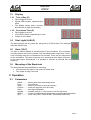
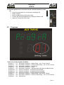
Version-E101025
Manual
Version-E101025
Manual
ASC2
Important Information
General
Before using your ALGE-TIMING device read the complete manual carefully. It is part of the device and
contains important information about installation, safety and its intended use. This manual cannot
cover all conceivable applications. For further information or in case of problems that are mentioned
not at all or not sufficiently detailed, please contact your ALGE-TIMING representative. You can find
contact details on our homepage www.alge-timing.com
Safety
Apart from the information of this manual all general safety and accident prevention regulations of the
legislator must be taken into account.
The device must only be used by trained persons. The setting-up and installation must only be executed according to the manufacturer’s data.
Intended Use
The device must only be used for its intended applications. Technical modifications and any misuse
are prohibited because of the risks involved! ALGE-TIMING is not liable for damages that are caused by
improper use or incorrect operation.
Power supply
The stated voltage on the type plate must correspond to voltage of the power source. Check all connections and plugs before usage. Damaged connection wires must be replaced immediately by an
authorized electrician. The device must only be connected to an electric supply that has been installed
by an electrician according to IEC 60364-1. Never touch the mains plug with wet hands! Never touch
live parts!
Cleaning
Please clean the outside of the device only with a smooth cloth. Detergents can cause damage. Never
submerge in water, never open or clean with wet cloth. The cleaning must not be carried out by hose
or high-pressure (risk of short circuits or other damage).
Liability Limitations
All technical information, data and information for installation and operation correspond to the latest
status at time of printing and are made in all conscience considering our past experience and knowledge. Information, pictures and description do not entitle to base any claims. The manufacturer is not
liable for damage due to failure to observe the manual, improper use, incorrect repairs, technical modifications, use of unauthorized spare parts. Translations are made in all conscience. We assume no
liability for translation mistakes, even if the translation is carried out by us or on our behalf.
Disposal
If a label is placed on the device showing a crossed out dustbin on wheels (see drawing), the
European directive 2002/96/EG applies for this device.
Please get informed about the applicable regulations for separate collection of electrical and
electronical waste in your country and do not dispose of the old devices as household waste.
Correct disposal of old equipment protects the environment and humans against negative
consequences!
Copyright by ALGE-TIMING GmbH
All rights reserved. Any duplication, either in full or in part, requires the prior written consent of the
copyright holder.
Page 2
Manual
ASC2
Table of Contents
1
1.1
General .................................................................................................................. 5
Connections and Devices....................................................................................... 6
1.1.1
1.1.2
1.1.3
1.1.4
1.1.5
1.1.6
1.1.7
Green Push-Button (1)........................................................................................................................6
Black Push-Button (2).........................................................................................................................6
Start Input (3) - Green-Black Banana Socket .....................................................................................6
Contact for Countdown Interval Setting (4) .........................................................................................6
Start Output (6) ...................................................................................................................................6
ON-OFF Switch (13) ...........................................................................................................................6
POWER-LED (11)...............................................................................................................................6
1.2
1.3
Power Supply (8+12).............................................................................................. 6
Display.................................................................................................................... 7
1.3.1
1.3.2
Time of Day (E)...................................................................................................................................7
Countdown Time (D)...........................................................................................................................7
1.4
1.5
1.6
Start Light (A+B+C) ................................................................................................ 7
Horn (10+7) ............................................................................................................ 7
Mounting of the Startclock...................................................................................... 7
2
2.1
2.2
Operation .............................................................................................................. 7
Parameters............................................................................................................. 7
Starting up the Startclock ....................................................................................... 8
2.2.1
2.2.2
2.2.3
2.2.4
2.2.5
2.2.6
Memory...............................................................................................................................................8
Scanning GPS device.........................................................................................................................8
Setting Time of Day ............................................................................................................................8
Setting the Program............................................................................................................................9
Select the Countdown Interval ............................................................................................................9
Select the Brightness of the LED <brIgHt> .......................................................................................10
2.3
Programs.............................................................................................................. 11
2.3.1
2.3.2
2.3.3
2.3.4
2.3.5
2.3.6
2.3.7
2.3.8
2.3.9
2.3.10
2.3.11
Program P01 ....................................................................................................................................12
Program P02 ....................................................................................................................................13
Program P03 ....................................................................................................................................14
Program P04 ....................................................................................................................................15
Program P05 ....................................................................................................................................16
Program P60 ....................................................................................................................................17
Program P61 ....................................................................................................................................18
Program P62 ....................................................................................................................................19
Program P07 ....................................................................................................................................20
Program P08 ....................................................................................................................................21
Program P00 ....................................................................................................................................22
3
3.1
Parameter setting ............................................................................................... 23
Parameter Setting in the Startclock...................................................................... 23
3.1.1
3.1.2
3.1.3
3.1.4
3.1.5
3.1.6
3.1.7
3.1.8
Display the Start Times <dISStt>......................................................................................................23
Print the Memory <PrInt>..................................................................................................................24
Select the Program <ProgrA>...........................................................................................................24
Delete the Memory <StorE> .............................................................................................................24
Set the Countdown Time <Cd#>.......................................................................................................25
Set the Start Light <LIGHt> ..............................................................................................................26
Set the Tone of the Speaker <tOnE>................................................................................................27
Factory Settings <SEtUP>................................................................................................................28
3.2
Parameter setting by PC ...................................................................................... 28
4
4.1
4.2
RS 232 Interface ................................................................................................. 28
GPS-Receiver ...................................................................................................... 29
Commands for reading data from device: ............................................................ 30
4.2.1
4.2.2
4.2.3
4.2.4
Read memory: ..................................................................................................................................30
Clear memory: ..................................................................................................................................30
Get current values on-line:................................................................................................................30
Get current values: ...........................................................................................................................30
4.3
Commands for setting data: ................................................................................. 31
4.3.1
SET PROGRAM ...............................................................................................................................31
Page 3
Manual
ASC2
4.3.2
4.3.3
4.3.4
4.3.5
4.3.6
4.3.7
4.3.8
SET COUNTDOWN TIME ................................................................................................................31
SET CLOCK TIME............................................................................................................................31
SET START LIGHT ..........................................................................................................................31
SET DISPLAY...................................................................................................................................31
GOTO SLAVE MODE.......................................................................................................................31
GOTO MASTER MODE ...................................................................................................................31
SET BRIGHTNESS ..........................................................................................................................31
5
Technical Data .................................................................................................... 32
Page 4
Manual
ASC2
1 General
The startclock ASC2 is a device for sports with individual start and fixed countdown time. It
helps the athletes and starters to organize the start procedure. There are several programs
available to cover different sports. Each program has 9 different start interval times. An
acoustic countdown, a start light and a visible countdown will help you to organize the start
procedure.
A ........ Red start light
B ........ Yellow start light
C........ Green start light
D........ Countdown clock with adjustable start intervals
E ........ Time of day clock with hours, minutes and seconds
1 ........ Green push-button
2 ........ Black push-button
3 ........ Start input (e.g. startgate for skiing) with green and black banana socket
4 ........ Connector for push-button for start interval setting
5 ........ RS232 interface
6 ........ Start output with banana sockets
7 ........ Socket to connect an external speaker
8 ........ External 12V power connection (12 – 15 VDC)
9 ........ Volume for speaker
10 ...... Horn for internal countdown speaker
11 ...... Battery condition and charging LEDs
12 ...... Mains connector to recharge internal battery of built in power pack (100-240VAC)
13 ...... On / Off – switch
14 ...... Fuse 1.0 A for power supply
Page 5
Manual
ASC2
1.1
1.1.1
Connections and Devices
Green Push-Button (1)
The green push-button (1) is a manual start button. If you press this button it triggers a start
impulse (same as getting a start impulse from start input (3)). Furthermore, the green pushbutton is used for settings. You can change the blinking parameters.
1.1.2
Black Push-Button (2)
The black push-button (2) is to select the countdown time. If you press the black push-button
during the standard operation it allows you to change the interval time. Furthermore, the
black push-button is used to confirm parameters and move to other parameters.
1.1.3
Start Input (3) - Green-Black Banana Socket
At this input channel you can connect a start device (e.g. startgate or photocell). It stores the
start time and the led/leg time for the start. This time you can show on the time of day display, print on a printer or send to a PC by RS232.
Furthermore, this input channel is used to effect the synchronous start with another device. It
receives an external impulse for synchronization or, if you press the green push-button for
synchronization, it also outputs an impulse via this socket to another device.
1.1.4
Contact for Countdown Interval Setting (4)
At this red and black banana socket (4), you can connect a push-button. With this pushbutton you can change the countdown interval. If you use the manual countdown, this pushbutton starts the manual countdown.
Countdown Interval Setting:
• Press the push-button for 3 seconds - the time of day disappears from display (E).
• Cd# (# = number from 0 to 9) is shown. The number is blinking.
• In the countdown display (D) the set countdown time is shown.
• Press the push-button (short) to change the selected countdown time.
• To confirm the new countdown time, press the push-button for 3 seconds and the startclock will go back to countdown mode with the new start interval.
1.1.5
Start Output (6)
This connection sends an output impulse at the zero signal of the start interval. This impulse
can be used e.g. to start another timing device (start impulse).
1.1.6
ON-OFF Switch (13)
It switches the startclock on or off.
1.1.7
POWER-LED (11)
The power LEDs are red, yellow and green. The LEDs show the following status
• Green ......... battery full
• Yellow ........ charging(extern supply is connected)
• Red ........... low battery, device will switch off soon
1.2
Power Supply (8+12)
The power supply is built into the startclock. It has an input for 100-240V AC or 12 – 15 VDC.
The start clock has an internal battery. Connected to the mains the battery loads.
Working Time:
approximately for 8 hours at 20°C or 5 hours at –20°C
Charging Time:
about 20 hours with empty battery
Page 6
Manual
ASC2
1.3
1.3.1
•
•
•
1.3.2
•
•
•
1.4
Display
Time of Day (E)
Figure height is 55 mm
6 green LED numbers, separated by a
colon
The display shows hours, minutes,
and seconds (2 digits for seconds)
Countdown Time (D)
Figure height is 80 mm
3 red LED numbers, separated by a colon
3 digits for countdown
Start Light (A+B+C)
The start light has red (A), yellow (B), and green (C) LED clusters. The start light
looks like a traffic light.
1.5
Horn (10+7)
The horn is used to release an acoustic signal of the countdown. This countdown
normally lasts for the final 5 seconds. If the countdown takes longer than 10 seconds a warning tone can be released at 10 seconds. There are two frequencies
for the countdown. The lower frequency is for warnings and the higher frequency
for the start signal. Alternatively, it is possible to connect an external horn at
socket (7).
1.6
Mounting of the Startclock
The startclock has two possibilities for mounting:
• 3/8 inch screw for tripod in the centre of bottom side
• Two straps to hang it at a wall
2 Operation
2.1
Parameters
diSStt ............. display start times and led/leg-times
PrInt ............... print memory
StorE.............. select if you want to clear the memory
PrOGrA.......... select the program (from 00 to 99)
LIgHt .............. start light adjustment
Horn##........... speaker tone (# = Lo for low tone or Hi for high tone)
SEtUP............ to clear the adjusted setup and reset to the standard parameters
gPS................ when using GPS - offset of GMT (Greenwich mean time)
Page 7
Manual
ASC2
2.2
Starting up the Startclock
Switch the startclock on with the On/Off-Switch (12).
2.2.1
Memory
After the startclock is switched on you have the
possibility to clear the memory.
• It shows <StorE> in the time of day display
(E) and <YES> in the countdown display (D).
• With the green push-button (1) you switch between <YES> and <nO>
• YES save memory
• nO
clear memory
• With the black push-button (2) you confirm
the selection to clear or save the memory.
2.2.2
Scanning GPS device
After the memory is cleared or saved, the message
<SCAn gPS> is shown. Next 10 secs ASC2 scans
the serial port to receive time of day from GPS device. The baud rate is 9600. If GPS device is connected, the ASC2 waits as long as it needs to receive proper time packet from GPS. After the time
is received the ASC2 is ready to select the program.
To stop the GPS scanning press the black button
(2). Now you can set the time of day manually.
Attention: If the wrong time of day is shown (e.g. 2
hours late), you have to adjust the offset to the GMT (Greenwich mean time). This is done in
the parameter setup <gPS>.
2.2.3
Setting Time of Day
When not finding any GPS the ASC2 switches to
the manual setup for time of day. It shows the
time of day in hours, minutes and seconds. The
first digit blinks. Now you can set the time of day
(see below).
• You can set the time of day only after you
switch the startclock on.
• When the startclock is switched on it first
scans for a GPS receiver and if it does not
find any it shows the time of day after 10
seconds.
• The hours are blinking.
• With the green push-button (1) you can set
the hours (0 to 23 hours).
• With the black push-button (2), you can switch from hours to minutes.
• With the green push-button (1), you can set the minutes (0 to 59 minutes).
• With the black push-button (2), you can switch from minutes to seconds.
• With the green push-button (1), you can set the seconds (0 to 59 seconds).
• With the black push-button (2), you can switch back to hours, etc.
Page 8
Manual
ASC2
•
•
•
If you keep the black push-button (2) pressed for about 3 seconds, the time of day is
set and ready for synchronization. In the countdown clock field SnC is shown.
You synchronise with an impulse on the start input banana sockets (3) or by pressing
the green push-button (1).
When the time of day is started you can set the program you want to use.
2.2.4
Setting the Program
•
•
•
•
•
•
2.2.5
After the synchronization, the time of
day display (E) shows the running time
of day for five seconds.
After five seconds the time of day disappears and <ProgrA> is shown in the
time of day display (E).
The countdown display (D) shows the
last used program number (0 to 5).
With the green push-button (1) you can
select the program number.
With the black push-button (2) you can
confirm the selected program number.
The startclock is now running in the selected program with the corresponding countdown interval 1.
Select the Countdown Interval
As soon as the program is selected, you can
change the countdown time at any time. When
changing the countdown time the new countdown
time is calculated. Zero point for the new countdown is always the zero tone of the last finished
countdown.
If you select the countdown interval and do not
change the interval time, the active countdown
continues without showing in the display. The
previous countdown only stops, when you select
a new countdown.
The countdown interval can be selected in two different ways:
a) Internal Black Push-button (2):
• Press the black push-button (2) and Cd# (# = number from 0 to 9)
is shown in display (E). The number is blinking.
• In display (D) the set countdown time is shown.
• With the green push-button (1) you can select between 9 different
pre-programmed countdown times.
• When the desired countdown time is shown in display (D) confirm
with the black push-button (2).
• Display (E) shows the time of day and display (D) the countdown
time. Zero of the new countdown time is the last finished zero time.
Page 9
Manual
ASC2
b) External push-button connected at red and black banana socket (4):
• Press the push-button for 3 seconds until display (E) shows
Cd# (# = number from 0 to 9). The number is blinking.
• Display (D) shows the set countdown time.
• Press the push-button for changing the selected countdown
time. You can select between 9 pre-programmed countdown
times.
• When display (D) shows the countdown time you want to set do
not press the push-button. After 3 seconds it is saved automatically.
• Time of day and running countdown are displayed. Zero of the
new countdown time is the last finished zero time.
c) Manual Countdown:
• If you select the manual countdown (e.g. program 06 and 00)
you need an external push-button to start each countdown as
shown in the picture on the right.
2.2.6
Select the Brightness of the LED <brIgHt>
The startclock has 10 brightness levels for the LED.
During breaks (e.g. between two runs for Alpine
Skiing) you should save battery power by setting
level off.
off.... LED off (power saving)
0...... LED lowest level
5...... LED medium level
9...... LED highest level
If you select level off (power saving), the startclock
does not show anything on the front face and also
stops the acoustic output (sound off).
As soon as you press the internal black push button (2) or the external push-button connected at banana socket (4) it returns to the previously set brightness mode.
a) Internal push-buttons:
• Press the black push-button (2) for six seconds until the display
(E)
• shows <brIGHT>.
• Set the brightness with the green push-button (1).
• Confirm the selected brightness with the black push-button (2).
Page 10
Manual
ASC2
b) External push-button connected at red and black banana socket
(4):
• Press the push-button for six seconds until display (E)
• shows <brigHT>.
• Set the brightness by pushing the button.
• Confirm the selected brightness by pressing the button until
• display (E) shows the time of day.
2.3
Programs
There are several programs available:
Program 1...... 01.... automatic countdown – Alpine Skiing – min. 30 sec. interval
Program 2...... 02.... automatic countdown – Cross Country Skiing – min. 30 sec. interval
Program 3...... 03.... automatic countdown – Car Racing
Program 4...... 04.... automatic countdown – Rallye
Program 5...... 05.... automatic countdown – Individual start with short countdown times
Program 60.... 61.... manual countdown – countdown reset possible
Program 61.... 61.... manual countdown – countdown timeout possible
Program 62.... 62.... manual countdown – countdown stopping possible
Program 7...... 07.... automatic countdown – Alpine Skiing – min 15 sec. interval
Program 8...... 08.... automatic countdown – Cross Country Skiing – min. 15 sec. interval
Program 0...... 00.... manual horn
Page 11
Manual
ASC2
2.3.1
Program P01
The countdown starts to automatically count a new interval after the zero tone. The allowed
start time is 5 seconds before or after the zero tone.
Sports:
Green/Black Banana Socket (3):
Red/Black Banana Socket (4):
White Banana Socket (6):
Countdown Intervals:
Alpine Skiing
start input by external start trigger device (e.g. startgate,
photocell)
to connect a push-button for set countdown time
output of start impulse (zero impulse)
CD1 = 0:30 min
CD2 = 0:40 min
CD3 = 0:45 min
CD4 = 1:00 min
CD5 = 1:15 min
CD6 = 1:30 min
CD7 = 1:40 min
CD8 = 2:00 min
CD9 = 2:30
CD0 = Break
Countdown Display (D)
10
9
8
7
6
5
4
3
2
1
0
-1
-2
-3
-4
-5
-6
-7
-8
-9
-10
Page 12
10
9
8
7
6
5
4
3
2
1
0
-1
-2
-3
-4
-5
-6
-7
-8
-9
-10
Start
Light
Red
Red
Red
Red
Red
Green
Green
Green
Green
Green
Green
Green
Green
Green
Green
Red
Red
Red
Red
Red
Red
Horn
low
off
off
off
off
low
low
low
low
low
high
off
off
off
off
off
off
off
off
off
off
Manual
ASC2
2.3.2
Program P02
The countdown starts to automatically count a new interval after the zero tone. The allowed
start time is 3 seconds before or after the zero tone.
Sports:
Green/Black Banana Socket (3):
Red/Black Banana Socket (4):
White Banana Socket (6):
Countdown Intervals:
Nordic Skiing – Cross Country
start input by external start trigger device (e.g. startgate,
photocell)
to connect a push-button for setting countdown time
output of start impulse (zero impulse)
CD1 = 0:30 min
CD2 = 0:40 min
CD3 = 0:45 min
CD4 = 1:00 min
CD5 = 1:15 min
CD6 = 1:30 min
CD7 = 1:40 min
CD8 = 2:00 min
CD9 = 2:30
CD0 = Break
Countdown Display (D)
10
9
8
7
6
5
4
3
2
1
0
-1
-2
-3
-4
-5
-6
-7
-8
-9
-10
10
9
8
7
6
5
4
3
2
1
0
-1
-2
-3
-4
-5
-6
-7
-8
-9
-10
Start
Light
Red
Red
Red
Red
Red
Red
Red
Green
Green
Green
Green
Green
Green
Red
Red
Red
Red
Red
Red
Red
Red
Horn
low
off
off
off
off
low
low
low
low
low
high
off
off
off
off
off
off
off
off
off
off
Page 13
Manual
ASC2
2.3.3
Program P03
The countdown starts to automatically count a new interval after the zero tone. The start light
switches to green when the countdown reaches zero.
Sports:
Green/Black Banana Socket (3):
Red/Black Banana Socket (4):
White Banana Socket (6):
Countdown Intervals:
Car Racing
start input by external start trigger device (e.g. startgate,
photocell)
to connect a push-button for setting countdown time
Output of start impulse (zero impulse)
CD1 = 0:30 min
CD2 = 0:40 min
CD3 = 0:45 min
CD4 = 1:00 min
CD5 = 1:15 min
CD6 = 1:30 min
CD7 = 1:40 min
CD8 = 2:00 min
CD9 = 2:30
CD0 = Break
Countdown Display (D)
10
9
8
7
6
5
4
3
2
1
0
-1
-2
-3
-4
-5
-6
-7
-8
-9
-10
Page 14
10
9
8
7
6
5
4
3
2
1
0
-1
-2
-3
-4
-5
-6
-7
-8
-9
-10
Start
Light
Red
Red
Red
Red
Red
Red
Red
Yellow
Yellow
Yellow
Green
Green
Green
Green
Green
Green
Green
Green
Green
Green
Red
Horn
low
off
off
off
off
low
low
low
low
low
high
off
off
off
off
off
off
off
off
off
off
Manual
ASC2
2.3.4
Program P04
The countdown starts to automatically count a new interval after the zero tone. The start light
switches to green when the countdown reaches zero. The countdown counts as far as – 20
seconds.
Sports:
Green/Black Banana Socket (3):
Red/Black Banana Socket (4):
White Banana Socket (6):
Countdown Intervals:
Rallye
start input from external start trigger device (e.g. startgate, photocell)
to connect a push-button for setting countdown time
Output of start impulse (zero impulse)
CD1 = 0:30 min
CD2 = 0:40 min
CD3 = 0:45 min
CD4 = 0:50 min
CD5 = 1:00 min
CD6 = 1:15 min
CD7 = 1:30 min
CD8 = 1:45 min
CD9 = 2:00 min
CD0 = Break
Countdown Display (D)
10
9
8
7
6
5
4
3
2
1
0
-1
-2
-3
-4
-5
-6
-7
-8
-9
-10
-11
-12
-13
-14
-15
-16
-17
-18
-19
-20
10
9
8
7
6
5
4
3
2
1
0
-1
-2
-3
-4
-5
-6
-7
-8
-9
-10
-11
-12
-13
-14
-15
-16
-17
-18
-19
-20
Start
Light
Red
Red
Red
Red
Red
Yellow
Yellow
Yellow
Yellow
Yellow
Green
Green
Green
Green
Green
Green
Green
Green
Green
Green
Green
Green
Green
Green
Green
Green
Green
Green
Green
Green
Red
Horn
low
off
off
off
off
low
low
low
low
low
high
off
off
off
off
off
off
off
off
off
off
off
off
off
off
off
off
off
off
off
off
Page 15
Manual
ASC2
2.3.5
Program P05
This is a simple repeatable countdown program that shows red before the zero tone and
green for two seconds after the zero tone. The minimum countdown time is 3 seconds.
Sports:
Green/Black Banana Socket (3):
Red/Black Banana Socket (4):
White Banana Socket (6):
Countdown Intervals:
Individual start with short countdown times
start input from external start trigger device (e.g. startgate, photocell)
to connect a push-button for setting countdown time
output of start impulse (zero impulse)
CD1 = 0:05 min
CD6 = 0:40 min
CD2 = 0:10 min
CD7 = 0:45 min
CD3 = 0:15 min
CD8 = 1:00 min
CD4 = 0:20 min
CD9 = 1:30 min
CD5 = 0:30 min
CD0 = Break
Intervals of 3 and 6 seconds:
Countdown Display (D)
3
2
1
0
next interval next
3
2
1
0
interval
Start
Light
Red
Red
Red
Green
Green
Horn
off
off
off
high
off
Intervals between 7 and 11 seconds:
Countdown Display (D)
5
4
3
2
1
0
next interval next
5
4
3
2
1
0
interval
Start
Light
Red
Red
Red
Red
Red
Green
Green
Horn
low
low
low
low
low
high
off
Intervals over 12 seconds:
Countdown Display (D)
10
10
9
9
8
8
7
7
6
6
5
5
4
4
3
3
2
2
1
1
0
0
next interval next interval
Page 16
Start
Light
Red
Red
Red
Red
Red
Red
Red
Red
Red
Red
Green
Green
Horn
low
off
off
off
off
low
low
low
low
low
high
off
Manual
ASC2
2.3.6
Program P60
The countdown starts to count down from an adjustable interval time after pressing the pushbutton (externally connected to red/black banana socket (4)). The start light switches to
green when the countdown reaches zero. After the countdown is at -10 no light and no
countdown time is displayed (only time of day).
If you press during the countdown the external push-button again it will reset the countdown.
Sports:
Green/Black Banana Socket (3):
Red/Black Banana Socket (4):
White Banana Socket (6):
Countdown Intervals:
Mass Start with Countdown for any Sport
start input from external start trigger device (e.g. startgate, photocell)
to connect push-button for activating start
output of start impulse (zero impulse)
CD1 = 0:10 min
CD6 = 0:40 min
CD2 = 0:15 min
CD7 = 0:45 min
CD3 = 0:20 min
CD8 = 1:00 min
CD4 = 0:25 min
CD9 = 1:30 min
CD5 = 0:30 min
CD0 = Break
Countdown
Display
10
9
8
7
6
5
4
3
2
1
0
-1
-2
-3
-4
-5
-6
-7
-8
-9
-10
10
9
8
7
6
5
4
3
2
1
0
-1
-2
-3
-4
-5
-6
-7
-8
-9
-10
Start
Light
Red
Red
Red
Red
Red
Red
Red
Yellow
Yellow
Yellow
Green
Green
Green
Green
Green
Green
Green
Green
Green
Green
Red
Horn
low
off
off
off
off
low
low
low
low
low
high
off
off
off
off
off
off
off
off
off
off
Page 17
Manual
ASC2
2.3.7
Program P61
The countdown starts to count down from an adjustable interval time after pressing the pushbutton (externally connected to red/black banana socket (4)). The start light switches to
green when the countdown reaches zero. After the countdown is at -10 no light and no
countdown time is displayed (only time of day).
If you press during the countdown the external push button again it stops the countdown
(timeout). Push the button again and the countdown will continue.
Sports:
Green/Black Banana Socket (3):
Red/Black Banana Socket (4):
White Banana Socket (6):
Countdown Intervals:
Page 18
Mass Start with Countdown for any Sport
start input from external start trigger device (e.g. startgate, photocell)
to connect push-button for activating start
output of start impulse (zero impulse)
CD1 = 0:10 min
CD6 = 0:40 min
CD2 = 0:15 min
CD7 = 0:45 min
CD3 = 0:20 min
CD8 = 1:00 min
CD4 = 0:25 min
CD9 = 1:30 min
CD5 = 0:30 min
CD0 = Break
Countdown
Display
10
9
8
7
6
5
4
3
2
1
0
-1
-2
-3
-4
-5
-6
-7
-8
-9
-10
10
9
8
7
6
5
4
3
2
1
0
-1
-2
-3
-4
-5
-6
-7
-8
-9
-10
Start
Light
Red
Red
Red
Red
Red
Red
Red
Yellow
Yellow
Yellow
Green
Green
Green
Green
Green
Green
Green
Green
Green
Green
Red
Horn
low
off
off
off
off
low
low
low
low
low
high
off
off
off
off
off
off
off
off
off
off
Manual
ASC2
2.3.8
Program P62
The countdown starts to count down from an adjustable interval time after pressing the pushbutton (externally connected to red/black banana socket (4)). The start light switches to
green when the countdown reaches zero. After the countdown is at -10 no light and no
countdown time is displayed (only time of day).
If you press during the countdown the external push button again it stops the countdown and
shows the time of day only. If you press the external push button again it starts a new countdown.
Sports:
Green/Black Banana Socket (3):
Red/Black Banana Socket (4):
White Banana Socket (6):
Countdown Intervals:
Mass Start with Countdown for any Sport
start input from external start trigger device (e.g. startgate, photocell)
to connect push-button for activating start
output of start impulse (zero impulse)
CD1 = 0:10 min
CD6 = 0:40 min
CD2 = 0:15 min
CD7 = 0:45 min
CD3 = 0:20 min
CD8 = 1:00 min
CD4 = 0:25 min
CD9 = 1:30 min
CD5 = 0:30 min
CD0 = Break
Countdown
Display
10
9
8
7
6
5
4
3
2
1
0
-1
-2
-3
-4
-5
-6
-7
-8
-9
-10
10
9
8
7
6
5
4
3
2
1
0
-1
-2
-3
-4
-5
-6
-7
-8
-9
-10
Start
Light
Red
Red
Red
Red
Red
Red
Red
Yellow
Yellow
Yellow
Green
Green
Green
Green
Green
Green
Green
Green
Green
Green
Red
Horn
low
off
off
off
off
low
low
low
low
low
high
off
off
off
off
off
off
off
off
off
off
Page 19
Manual
ASC2
2.3.9
Program P07
The countdown starts to automatically count a new interval after the zero tone. The allowed
start time is 5 seconds before or after the zero tone.
In this program you can set the start light and the horn from 10 seconds to – 5 seconds (altogether 15 seconds). This allows shorter start intervals (shortest interval time is 15 sec.)
Sports:
Green/Black Banana Socket (3):
Red/Black Banana Socket (4):
White Banana Socket (6):
Countdown Intervals:
Alpine Skiing
start input from external start trigger device (e.g. startgate, photocell)
to connect a push-button for setting countdown time
output of start impulse (zero impulse)
CD1 = 0:15 min
CD2 = 0:20 min
CD3 = 0:30 min
CD4 = 0:40 min
CD5 = 0:45 min
CD6 = 1:00 min
CD7 = 1:15 min
CD8 =:1:20 min
CD9 = 1:30 min
CD0 = Break
The table below shows the ASC2 at a 15 second interval:
Countdown Display (D)
10
9
8
7
6
5
4
3
2
1
0
-1
-2
-3
-4
-5
Page 20
10
9
8
7
6
5
4
3
2
1
0
14
13
12
11
10
Start
Light
Red
Red
Red
Red
Red
Green
Green
Green
Green
Green
Green
Green
Green
Green
Green
Red
Horn
low
off
off
off
off
low
low
low
low
low
high
off
off
off
off
off
Manual
ASC2
2.3.10 Program P08
The countdown starts to automatically count a new interval after the zero tone. The allowed
start time is 3 seconds before or after the zero tone.
In this program you can set the start light and the horn from 10 seconds to – 5 seconds (altogether 15 seconds). This allows shorter start intervals (shortest interval time is 15 sec.)
Sports:
Green/Black Banana Socket (3):
Red/Black Banana Socket (4):
White Banana Socket (6):
Countdown Intervals:
Nordic Skiing – Cross Country
start input from external start trigger device (e.g. startgate, photocell)
to connect a push-button for setting countdown time
output of start impulse (zero impulse)
CD1 = 0:15 min
CD2 = 0:20 min
CD3 = 0:30 min
CD4 = 0:40 min
CD5 = 0:45 min
CD6 = 1:00 min
CD7 = 1:15 min
CD8 =:1:20 min
CD9 = 1:30 min
CD0 = Break
The table below shows the ASC2 at a 15 second interval:
Countdown Display (D)
10
9
8
7
6
5
4
3
2
1
0
-1
-2
-3
-4
-5
10
9
8
7
6
5
4
3
2
1
0
14
13
12
11
10
Start
Light
Red
Red
Red
Red
Red
Red
Red
Green
Green
Green
Green
Green
Green
Red
Red
Red
Horn
low
off
off
off
off
low
low
low
low
low
high
off
off
off
off
off
Page 21
Manual
ASC2
2.3.11 Program P00
The countdown starts showing the time of day, start light red. When you press the pushbutton (externally connected to red/black banana socket (4)), it switches to green for 5 seconds and a high tone sounds (for one second).
Sports:
Green/Black Banana Socket (3):
Red/Black Banana Socket (4):
Countdown Intervals:
Push
Button
off
on
off
off
off
off
off
Page 22
Mass Start for any Sport
start input from external start trigger device (e.g. startgate, photocell)
to connect push-button for activating start
manual mode
Display
--GO
GO
GO
GO
GO
---
Start
Light
Red
Green
Green
Green
Green
Green
Red
Horn
off
high
off
off
off
off
off
Manual
ASC2
3 Parameter setting
To set the parameters you have two possibilities:
• Parameter setting in the startclock
• Parameter setting from a PC
3.1
Parameter Setting in the Startclock
To enter the parameter setting menu press black push-button (2) for about 9 seconds until
the time of day display (E) shows <dISSTF>.
With green push-button (1) you can choose the parameter you want to change. Confirm with
black button (2). With green push-button (1) you can change the parameter. With black button (2) the change is confirmed.
With green button (1) you can proceed to another parameter. If no button is pressed for the
next 3 seconds you automatically exit the parameter mode.
dISStt............. display start time of first competitor
PrInt ............... print memory
PrOGrA.......... select the program (from 00 to 99)
StOrE............. select if you want to clear the memory
Cd# ................ countdown time #
LIGHt ............. start light adjustment
tOnE# ............ speaker tone (# = L for low tone or H for high tone)
SEtUP............ to reset all parameters to standard (company setup)
3.1.1
Display the Start Times <dISStt>
The display (E) shows blinking <dISStt> (Display Start Time).
•
•
•
•
•
•
•
•
•
Press the green push-button (1) and display (E) shows the start time of the previous
competitor
On display (D) you see the lead/leg time.
If the start light is yellow, the start was after the zero impulse.
If the start light shows green, the start tolerance was okay.
If the start light shows red, the start was outside the start tolerance
If you press green button (1) the start time of the starter before is shown, etc.
If you press green push-button (1) the display shows the start time of the previous
competitor.
Press the black button (2) and the previous time is displayed once again.
To leave the menu you keep black push-button (2) pressed until display (E) shows
blinking < PrInt > again.
If you want the first time to be shown, press the black push-button (2) when the display
shows the last start number.
Page 23
Manual
ASC2
3.1.2
Print the Memory <PrInt>
Display (E) shows <PrInt> and display (D) shows <oFF>. If you activate the print mode, it
outputs the consecutive number, start time and led/leg time for each start.
0001 ST
0002 ST
0003 ST
•
•
•
•
•
•
•
•
•
10:00:00.1431
+0.1431
10:00:59.3844
-0.6156
10:02:01.3217
+1.3217
Press green push-button (1) and display (D) shows <onL>. The startclock now prints
every zero time, the official start time and the led/leg time online.
For activating the online mode press the black button (2).
For deactivating the online mode press the green button (1) again. The display (D)
shows <ALL>.
If you confirm with black button (2), the complete memory is printed.
On display (D) you see the led/leg time
If the yellow light shines, the start was carried out after the zero impuls
If the green light shines, the start tolerance was okay
If the red light shines, the start was carried out outside the start tolerance
To exit the printer menu press the balck button (2) until display (E) shows <PrOGrA>
3.1.3
Select the Program <ProgrA>
The display (E) shows <ProgrA> and the display (D) shows the currently selected program
number. Here, you can move to another program.
• The countdown display (D) will show the current program number (0 to 5).
• With green push-button (1) you can select the program number.
• With black push-button (2) you can confirm the selected program number.
• The startclock now runs in selected program with countdown interval 1 of this program.
3.1.4
Delete the Memory <StorE>
The display (E) shows <StorE>. Now you can delete the memory.
• It shows <StorE> in the time of day display (E) and in display (D) <YES>.
• With green push-button (1) you switch between <YES> and <nO>
• YES....... save memory
• nO ......... clear memory
• With black push-button (2) you confirm the selection to clear or save the memory.
Page 24
Manual
ASC2
3.1.5
Set the Countdown Time <Cd#>
For each program you have 9 different countdown times (Cd1 to Cd9). Additionally, you have
Cd0 that is always the break (no countdown) if the time of day display (E) shows <Cd#>
When you select the menu to set the countdown times, you set the countdown times of the
current program.
•
•
•
The shortest allowed countdown time is 20 seconds, the longest 9:59 minutes.
You cannot change a countdown in program 5 and 0.
You can never change the set countdown time and the Cd0 (manual countdown
time or break).
•
The display (E) shows <Cd#> (# = number of 0 to 9) and the countdown display (D)
shows the set countdown time.
Press black push-button (2) to select the countdown time that you change.
Now, the first digit of the countdown times blinks.
Press green push-button (1) to change the digit.
Press black push-button (2) to move to the next digit.
Press green push-button (1) to change the digit.
Press black push-button (2) to move to the last digit.
Press green push-button (1) to change the digit.
Press black push-button (2) to move to the first digit, etc.
To exit the selected countdown press black push-button (2) until display (E) shows
again <Cd#>. No digit blinks any more.
To exit the countdown menu press black push-button (2) until display (E) shows
<LIGth>.
•
•
•
•
•
•
•
•
•
•
Page 25
Manual
ASC2
3.1.6
Set the Start Light <LIGHt>
The start light has three colors – red, yellow and green. You can set the start light for a certain time. In case the selected times are beyond the time of the start interval, the countdown
of the start interval shows the current color of light. The set values always apply to all countdowns in this program (except Cd0). Display (E) shows <LigHt> (light) and display (D) shows
the selected time. The start light shows the set color for this time.
Display (E) shows <LigHt> and the countdown dipslay (D) the time. The start light shows red,
yellow, green or all colors (light is switched off). When pressing the black button (2) the light
blinks.
• Press green button (1) to change the light color
• Press black button (2) to save the light color and to move to time.
• The first digit of the time blinks (display D)
• Press green push-button to set first digit of the time
• Press black push-button (2) to move to second digit
• Press green push-button (1) to set this digit
• Press black push-button (2) to move to last digit
• Press green button to set this digit
• Press black button to move to next start light position etc.
• To exit the start light menu press black button (2) until display (E) show <tOnE#>
Example:
Start Light = red
Start Light = yellow
Start Light = green
Start Light = red
Start Light = black
Page 26
Countdown Time = 10
Countdown Time = 5
Countdown Time = 3
Countdown Time = -3
Countdown Time =-10
Countdown
Display
11
10
9
8
7
6
5
4
3
2
1
0
-1
-2
-3
-4
-5
-6
-7
-8
-9
-10
-11
11
10
9
8
7
6
5
4
3
2
1
0
-1
-2
-3
-4
-5
-6
-7
-8
-9
-10
-11
Traffic
Light
no
Red
Red
Red
Red
Red
Yellow
Yellow
Green
Green
Green
Green
Green
Green
Red
Red
Red
Red
Red
Red
Red
Red
no
Manual
ASC2
3.1.7
Set the Tone of the Speaker <tOnE>
The tone of the speaker can be switched off, sound with a high or a low tone. Most sports
desire a pre-warning at 10 seconds and a countdown from 5 seconds to 0. The set values
always apply for all countdowns in this program (not Cd 0).
• The display (E) shows blinking <tOnE#> (# = L [low] or H [high])
• Press the green button (1) to switch between L and H (low or high signal tone)
• Press black button (2) to confirm moving on to countdown time and saving signal tone
• The first digit of the time blinks (display D)
• Press green button (1) to change first digit of singal tone time
• Press black button (2) to move to second digit
• Press green button (1) to change second digit
• Press black button (2) to move to last digit
• Press green button (1) to change last digit
• Press black button (2) to move to next tone etc.
• To exit the signal tone menu press black button (2) until display (E) show <StOrE>
Example:
Horn Low
Horn Low
Horn Low
Horn Low
Horn Low
Horn Low
Horn High
Countdown
10
9
8
7
6
5
4
3
2
1
0
-1
-2
-3
-4
-5
-6
-7
-8
-9
-10
Countdown Time = 10
Countdown Time = 5
Countdown Time = 4
Countdown Time = 3
Countdown Time = 2
Countdown Time = 1
Countdown Time = 0
Horn
low
off
off
off
off
low
low
low
low
low
high
off
off
off
off
off
off
off
off
off
off
Page 27
Manual
ASC2
3.1.8
Factory Settings <SEtUP>
It is possible to change many parameters of the ASC2. If you have troubles with the changes
you made, we recommend resetting the ASC2 to factory settings. This means all the settings
you changed are reset to factory values.
• The display (E) shows blinking <SEtUP> (SETUP).
• Display (D) shows <CUS>. This means customer settings are saved after switching on
and off.
• Press black push-button (2) and display (D) blinks.
• Press green push-button (1) and you can change between <CUS> (= customer) and
<STA> (= standard).
• If the display shows <STA> and you press black push-button (2), all parameters are reset to the factory values (original setting).
Attention:
3.2
The startclock automatically keeps the customer values that you set. To reset
these values to the factory values you have to proceed as described above.
Parameter setting by PC
We can offer software to effect the parameter settings by PC. This is much faster
and easier. You can download software from our homepage www.alge-timing.com
free of charge.
4 RS 232 Interface
The RS232 interface has different functions:
• Remote control connection (e.g. device to control the startclock)
• Output of time difference of all start times: times from start input (3) (green and black
banana socket) and lead/leg times
• RS 232 interface to control the startclock from a PC (time of day display, countdown
display, horn, start light)
• Connection for the printer P5 to print all times online or offline.
Interface parameter:
• RS 232
• 1 start bit, 8 data bit, 1 stop bit, no parity bit
• 2400 baud rate (for printer 2400)
Page 28
Manual
ASC2
4.1
GPS-Receiver
The startclock ASC2 always shows the time of day. It is possible
to set the time of day manually or automatically by a GPSreceiver (optional). The GPS-receiver is connected at the RS232
interface (5). Using the GPS receiver the ASC2 reaches an
accuracy of up to 1/1000 seconds. The time that the GPSreceiver obtains is always the GMT (Greenwich Mean Time). In
order to display the correct time of your time zone, you have to
set an offset to the GMT time in the parameter setup.
Parameter <gPS>
To set the time of day with a GPS-receiver connect it at the RS232 interface (5) of the ASC2.
Position the GPS-receiver in such a way that it has unhindered view to the sky. In order to
receive the time the GPS-receiver requires the data of four different satellites. This process
may take some minutes.
Page 29
Manual
ASC2
4.2
Commands for reading data from device:
4.2.1
Read memory:
PC to ASC2:
ACS2 to PC:
?MCR
M? XXXX ST HH:MM:SS:zht LT –SS.zhtCR
M? EMPTYCR
XXXX .........................start number
ST
HH:MM:SS.zht ...........start time
LT
– .................................sign
SS.zht.........................lead or leg time
EMPTY.......................memory is empty
4.2.2
Clear memory:
PC to ASC2:
ACS2 to PC:
4.2.3
?ECR
E?CR
Get current values on-line:
PC to ASC2 to start:
?DCR
PC to ASC2
to stop and send again: ?DCR
ACS2 to PC:
D? HH:MM:SS m:ss C HCR
HH ..............................hours
MM .............................minutes
SS ..............................seconds
m ................................current countdown time minutes
ss................................current countdown time seconds
C.................................color (Black=0, Red=1, Yellow=2, Green=3)
4.2.4
Get current values:
PC to ASC2:
?SCR one time
ACS2 to PC:
S? HH:MM:SS m:ss C XX m:ss bCR
HH ..............................hours
MM- ............................minutes
SS ..............................seconds
m ................................current countdown time minutes
ss................................current countdown time seconds
C.................................color (Black=0, Red=1, Yellow=2, Green=3)
XX ..............................program
m ................................CDT minutes
ss................................CDT seconds
b .................................brightness
Page 30
Manual
ASC2
4.3
4.3.1
Commands for setting data:
SET PROGRAM
PC to ASC2:
=PXCR
X.................................program (0-9)
ACS2 to PC:
P=CR
4.3.2
SET COUNTDOWN TIME
PC to ASC2:
=CSCR
S.................................countdown time (0-9)
ACS2 to PC:
C=CR
4.3.3
SET CLOCK TIME
PC to ASC2:
ACS2 to PC:
4.3.4
=THHMMSS CR
T=CR
SET START LIGHT
PC to ASC2:
=LXSSTHCR
X.................................program (0-9)
SS ..............................seconds (0-20, 0=-10, 20=10)
T .................................color (0-off, 1-red, 2-yellow, 3-green)
H.................................sound (0-off, 1-high, 2-low)
ACS2 to PC:
L=CR
4.3.5
SET DISPLAY
Has effect only if device is in slave mode
PC to ASC2:
=DHHtpMMtpSSmtpssTHCR
HH..............................hours
MM.............................minutes
SS ..............................seconds
M................................countdown time minutes
ss ...............................countdown time seconds
T.................................color (0-off, 1-red, 2-yellow, 3-green)
H ................................sound (0-off, 1-high, 2-low)
Tp...............................two points
ACS2 to PC:
D=CR
4.3.6
GOTO SLAVE MODE
PC to ASC2:
ACS2 to PC:
4.3.7
GOTO MASTER MODE
PC to ASC2:
ACS2 to PC:
4.3.8
=SLAVECR
S=CR
=MASTERCR
S=CR
SET BRIGHTNESS
PC to ASC2:
=BXCR
X ............................................brightness (0-9)
ACS2 to PC:
B=CR
Page 31
Manual
ASC2
5 Technical Data
Timing range:
Accuracy:
Precision:
Quartz frequency:
Time of Day LED-Field:
Countdown LED-Field:
Start Light:
Extern Speaker:
Operative temperature range:
Memory:
RS232 Interface:
1…TX
2…Ground
3…RX
4…empty
5…empty
6…GPS sync.
7…+12 VDC
8…empty
Battery:
Ext. Power Supply:
DC-Power: 12 – 15 VDC
Case:
Measurements:
Weight:
23 hours, 59 minutes, 59,999 seconds
+/- 0,0002 sec/h at 20°C (68 K)
+/- 0,009 sec/h at -15 to 50 °C (5 to 122 K)
1/1000 seconds
TCXO 32.754 kHz (temperature compensated crystal oscillator)
Six 7-segment LED figures with a figure height of 55 mm, separated after every second figure by three dots
Three 7-segment LED figures with a figure height of 80 mm,
separated between the first and second figure by three dots
Start light consisting of 3 LED clusters (red, yellow, green)
8 Ohm
-25 to 60°C (-13 to 140 F)
about 2000 start times
PC:
2400 Baud, 1 start bit, 8 data bit, 1 stop bit, no parity bit
Printer: 2400 Baud, 1 start bit, 8 data bit, 1 stop bit, no parity bit
12 VDC, 7.2 Ah
AC-Power: 100 – 240 VAC
Aluminum case for outdoor use
380 x 310 x 110 mm (18.4 x 13.5 x 4.5 in.)
6.3 kg (14 lbs.)
Subject to changes
Copyright by
ALGE-TIMING GmbH
Rotkreuzstr. 39
6890 Lustenau / Austria
www.alge-timing.com
Page 32