1
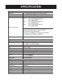
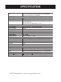
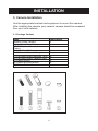
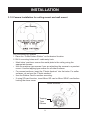
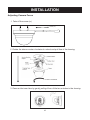
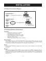
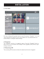
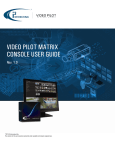
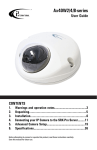
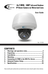
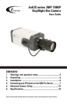
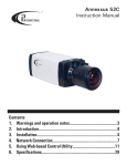
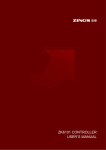
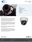
Ax52 Dome Camera Series
Instruction Manual
Rev. 141120
CONTENTS
SAFETY INFORMATION..................................................... 2
PRODUCT OVERVIEW ....................................................... 4
SPECIFICATION................................................................ 6
INSTALLATION..................................................................
8
Before attempting to connect or operate this product, please read these
instructions carefully and save this manual for future use.
SAFETY INFORMATION
When installing your Annexxus system, be sure to avoid:
• excessive heat, such as direct sunlight or heating appliances
• moisture, dust, and smoke
• strong magnetic fields
• close to sources of powerful electromagnetic radiation, such as radios or TV transmitters
• close to humid or excessively dusty places
• where exposed to mechanical vibrations
• close to fluorescent lamps or objects reflecting light
• under unstable light sources (may cause flickering)
• temperatures below 10° Celsius or 14° Fahrenheit and above 50° Celsius or 122° Fahrenheit for AX41C1M
Power Supply
• Ensure the supplied voltage meets the power consumption
requirements of this camera before powering the camera on.
Incorrect voltage may cause irreparable damage to the video
camera and will effectively void the camera warranty
Cleaning
• For maximum optical clarity, the camera dome or lens must remain clean. Use a soft, dry cloth to remove finger prints or dust
from the dome cover.
• Use a blower to remove dust from the lens.
• Clean the body with a soft, dry cloth. If it is very dirty, use a cloth dampened with a small quantity of neutral detergent, then
wipe dry.
• Do not use volatile solvents such as alcohol, benzene, or thinners, as they may damage the surface finishes.
Servicing
• To avoid electrical shock and to preserve the product warranty,
DO NOT disassembles the camera. Refer servicing to qualified
personnel only.
2
SAFETY INFORMATION
The triangle symbol with lightning arrow indicates
that ungrounded “Hazardous Voltage” exists within
the unit. The voltage level may cause personal
electric shock hazards.
The triangle symbol with exclamation mark
indicates that there are important operation and
maintenance instructions in the Instruction Manual.
3
PRODUCT OVERVIEW
1. Key Features
High Definition Images
Clear and detailed HD quality images in all conditions. Unlike other
megapixel cameras, AX52 offers higher resolutions and better frame
rates. Blurry images are reduced and individuals and objects of
interest come with perfect clarity.
Triple Streaming
The AX52 Network Camera is designed to show extreme image
detail. H.264/MPEG4/MJPEG triple streaming allows you to choose
the appropriate code for your bandwidth.
Cost-saving H.264 Support
The AX52 supports the H.264 compression standard. H.264 greatly
reduces the size of video without compromising image quality.
Storage and bandwidth are reduced.
4
PRODUCT OVERVIEW
2. Camera Overview
2.0 Camera Parts and Definitions
• Power In (Red+/Black-): power connector,
DC12V/AC24V
• RJ-45 Ethernet Connector: network connection. Support
PoE (Power over Ethernet) cable.
• BNC: video output
• Audio Out (Green): audio output
• Audio In (Red): audio input
• Alarm Out (Orange): alarm signal output port /Reserved
(Green)/ Reserved (Yellow)/
• GND: ground (electricity) in electrical circuits/Alarm In 1 (Red): alarm signal input port/Alarm In 2 (Brown):
alarm signal input port
• Reset: use an appropriate tool to press the button to reset the camera (Hold for 5 seconds to reboot
camera. Hold longer than 5 seconds to load default settings)
Note: If PoE (Power over Ethernet) connector is used, it eliminates need for Power In cable.
5
SPECIFICATION
Image system
Image sensor
Effective pixels
Image Compression Method
1/3" 2 MP image sensor optimized for low-light performance
Effective 16:9 1920 (H) X 1080 (V)
Triple Streaming : H.264 / MPEG4 / Motion JPEG
H.264
MPEG4
MJPEG
(16:9): 1920X1080(2M) 1280X720
(4:3): 1280x960(SXVGA)
(16:9): 1920X1080(2M) 1280X720
(4:3): 1280x960(SXVGA)
(16:9): 1920X1080(2M) 1280X720
(4:3): 1280x960(SXVGA)
Video Codec / Resolution
Primary Stream Video Compression: H.264 or MPEG-4 or MJPEG
Secondary Stream Video Compression: H.264 or MPEG-4
Third Stream Video Compression: MJPEG
Frame rate up to 15fps(NTSC) and 12.5fps(PAL) at 1920x1080;
up to 30fps(NTSC) and 25fps(PAL) at 1280x720
Len
Electric
Sync system
AES
Audio
Alarm
RS485
Day & Night Mode
Minimum illumination
Video port
TV output
Intelligent video
Feature
Exposure mode
BLC
ATR/D-WDR
White Balance
Sharpness
Saturation
Brightness
Contrast
Privacy Zone
Built-in Mechanical ICR Filter varifocal lens f=3~9mm, F1.2 (Mega pixel
lens)
Internal
NTSC: 1/10000 s to 1/3.75s (selectable);
PAL: 1/10000 s to 1/3.125s (selectable)
Two-way Mono Audio, Full-duplex, G.711 PCM 8kHz
2 Inputs / 1 Output
Reserved
ICR D/N control; Auto/ Forced BW/ Forced Color/ External
0.08 Lux @10IRE; 0.3Lux @50IRE
BNC X1, 1.0Vp-p, 75Ω / RCA x 1
NTSC, 720 X 480 @30fps
PAL, 720 X 576 @25fps
Video motion detection
Auto/Manual
5 x 5 zones selectable
Digital wide dynamic range
Auto/Manual
255 level sensitivity
255 level sensitivity
255 level sensitivity
255 level sensitivity
Yes; customized threshold privacy zone
6
SPECIFICATION
Other
Local Storage
Memory Card
SD card overwrite
SD card store category
Power Supply
Power requirement
Power consumption
Power connector
Environment
Operating temperature
Operating humidity
Storage temperature
Network
Ethernet
Internet protocol
IP
Connectors
Control interface
I/O connector
Alarm port
Audio In / Out port
Reset
Mechanism
Dimensions( xH)
Weight (Camera Only)
Mirror, Flip, System log, Time stamp, Snapshot, Event Management
Primary Stream Bit Rate Control: CBR/VBR
Support Micro SD/ Micro SDHC Card up to 32 GB
Yes
Alarm /Ethernet Fail
file format JPEG/ AVI
Recording frame rate range between 1 to 3 fps
DC 12V & AC 24V ± 10% / PoE(IEEE 802.3af)
5W Max
Screwless Terminal block
-10ºC ~ 50ºC (14ºF ~ 122ºF)
10~90% RH
-20ºC ~ 60ºC (-4ºF ~ 140ºF)
10/100 base-T Ethernet connection for LAN/WAN
TCP/IP, UDP, HTTP, FTP, DNS, DHCP, NTP, RTP,RTSP, ICMP, uPNP
IPv4
RJ-45
IE browser 6.0 or above
Terminal block 2 in / 1 out
3.5mm Phone Jack x 2
Within 5 sec for rebooting system; more than 5 sec for loading default
O138mm x H102mm (O54inch x H40 inch)
1.13kg (2.5lb)
NOTE:The specification is subject to change without notice.
7
INSTALLATION
3. Camera Installation
Use the appropriate brackets and equipment to mount this camera.
After installing the camera, your network camera should be accessed
from your local network.
3.1 Package Content
Item
Description
Network Dome Camera
Printed Quick Start Guide
CD-ROM ( User Manual, Annexxus
Finder )
Guide Pattern Sticker
RJ45 Female / Female Coupler
(1) Flat Hand Screw (Machine Type)
(2) Flat Hand Screw (Tapping Type)
(3) Plastic Anchor
(4) Plastic Mounting Button
(5) Rubber Feet
x1
x1
x1
x1
x1
x4
x4
x4
x4
x4
8
INSTALLATION
3.1.5 Camera Installation for ceiling mount and wall mount
Drill the Mounting Location
1. Place the “Guide Pattern Sticker” on the desired location.
2. Drill 4 mounting holes and 1 cable entry hole.
• Mark holes’ positions: secure the metal plate to the ceiling using the
appropriate screws.
• Use the machine type screws if you are attaching the camera to a pendent
mount. Use the tapping type screws for all other surfaces.
• For cement surfaces, insert the “Plastic Anchors” into the holes. For softer
surfaces, do not use the “Plastic anchors”.
• Use the Rubber Feet for surface mounting.
• If using SD card function, insert Micro SD card or Micro SDHC card before
locking the dome cover.
Plastic Anchors
Tapping
Type
Screws
9
INSTALLATION
Adjusting Camera Focus
1. Take off the screw (a.)
Screw (a.)
2. Rotate the dome counter clockwise to unlock and pull free of the housing.
Counter Clockwise
3. Remove the inner liner by gently pulling it free of the two notches in the housing.
10
INSTALLATION
4. Adjust the camera to your specification (Tilt).
Pan (Angle about
355 degrees)
Tilt(Angle 90 degrees)
5. Adjust the camera to your specification (Pan).
Horizontal Rotation
Note: When the tilt angle is less than
75 degrees there is no distortion
11
INSTALLATION
6. Focusing loosen both screws (a.) and (b.) and turn the lens until ideal picture
Screw (a.)
Screw (b.)
Varifocal
Lens
7. Reattach the inner liner and dome when you are done adjusting the focus.
12
INSTALLATION
3.2 Network Connection Diagram
3.2 Hardware/Software Requirement
Computer
• i3 SRX-Pro Version 2.0 or higher
• Windows Vista or XP as OS
• Internet Explorer Version 6.0 or later
• CPU: Intel Pentium Core 2 or higher
• Memory: 1GB or more
• VGA card--support Direct X 9.0 or above
Power Supply
The camera requires a DC12V/AC24V/PoE power supply. Make sure you use the
correct power supply before connecting to this network camera. Use a RJ45 network
connector to connect the camera to your computer or hub switch.
Switch
A one Gigabit Switch is required to monitor two or more cameras from the same
computer.
SD card
The camera supports Micro SDHC memory cards up to 32GB. Images can be recorded when the SD card is being inserted into the camera. Insert a SD card before
switching on the camera. The SD card may not be detected if it is inserted while the
camera is on.
13
INSTALLATION
3.4 Connecting the Camera to a Personal Computer
This section details how to access the camera from a computer.
3.4.1 Setting IP
This is a network-based camera and must be assigned an IP address first.
• Enter a default IP address manually. The camera’s default IP address is
192.0.0.16 and subnet mask address is 255.255.255.0.
• Obtain an IP address automatically from the DHCP server. You don’t need
to change the camera’s IP address if your network uses a DHCP server.
3.4.2 Connect the Camera to a Personal Computer
1. Connect the network cable to the camera and then turn on the
camera’s power.
2. Set the personal computer’s IP address. The camera’s default IP address:
192.0.0.16 and subnet mask is 255.255.255.0.
3. Check that the camera and computer are connected by pinging the IP
address you have set. To do this, start a command prompt and type the
IP address you set. If the message “Reply from…” appears, it means the
connection is done.
14
INSTALLATION
4. Start Internet Explorer and enter the set IP address (default is http://192.0.0.16).
A login window will appear. Enter the default user name and to login.
Default Login/Password:
Firmware Version:
AP_01-00-60-33_i02
Login: admin
Password: 1234
Firmware Version:
AP_01-00-60-35_i02, or
higher
Login: i3admin
Password: i3admin
5. Then you should be able to see the camera image screen as follows:
15
INSTALLATION
3.5 Using “Annexxus Finder” to Search Camera’s IP Address
“Annexxus Finder” is a program which helps users finds network cameras. Please
note that “Annexxus Finder” is only compatible with Windows XP.
1.Insert the CD in the CD-ROM drive.
2.Double click “AnnexxusFinder.exer” to run the program. Follow the instructions
to install.
3.After successfully installing “Annexxus Finder”, double click the “Annexxus
Finder” icon which is displayed in your desktop. An “Annexxus Finder” window
will pop out. The window will display a list of net cameras which you are using
currently.
To edit network information for the selected IP camera, do the following:
1.Select desired camera in the Annexxus Finder software by double clicks
2.Go to the Change IP Address and enter the correct data for the IP camera
3.Please enter password before click save button.
16
INSTALLATION
4.1 Live View
Live view is designed for general users to control the camera. “Snapshot”, “Live” and
“Setup” functions are listed on the live view. Please note, only administrators can
access "Setup" to configure camera settings.
4.2 Snapshot
The “Snapshot” function is for snapshot capture. Press the “Snapshot” button to
take a link to let user choose local storage to save (jpg/bmp) user prefer by right
clicking on this link.
4.3 Recording LED
The recording LED becomes red when the alarm/event function is triggered.
17
INSTALLATION
5. Setup Mode
Click on “setup” to configure camera settings.
18
INSTALLATION
5.1 Basic Setting
Every parameter of “Basic Setting” affects the displayed image. Specify appropriate
parameters in the following section.
Advance or Basic Button
“Basic Image” is used to change any picture setting on the camera. Remember to
click “Save” to keep your settings.
• Camera Name: enter a desired network camera name. The name will be
displayed at the top of the live page.
• Video Codec: Choose a compression mode to be displayed in
“Live View”.
19
INSTALLATION
5.2 Advance Setting
Video Page
Frequency: “50 Hz” and “60 Hz” are provided for reducing flicker.
TV System: "NTSC" and "PAL" are provided for different TV system settings.
• Note: This setting base on model (NTSC/PAL) type.
Mirror:
• OFF: turn off this function.
• HORIZONTAL: set images as left or right.
• VERTICAL: set images as upside or down.
• BOTH: set the HORIZONTEL and VERTICAL settings.
Rate Control: Choose a bit rate control. Choices include:
• VBR (Variable Bit Rate) Variable Bit Rate control is for video storage
Ex: NVR local storage recording. Image quality is good, but the CPU loading
of camera is not stable for the variable scenes such as flickering tree and the
throughput of network is unstable for the variable scenes.
• CBR (Constant Bit Rate) Constant Bit Rate control is for video low delay.
(i.e., CBR with frames dropped based on image buffer occupancy.) The
streaming is smooth and the CPU loading of camera is stable for any scene
and the throughput of network is stable for the variable scenes.
20
INSTALLATION
MJPEG SETTING
• Resolution: Choose the resolution size. Choices include 1080P, SXVGA, 720P,
XGA, SVGA, D1
• Quality: Set the image’s quality as High, Normal or Low.
• Frame Rate: Frame rate is the image transfer speed. 30 fps is 30 image
transmissions per second, 15 is 15 images transmission per second, 7.5 is 7.5
images transmission per second…etc.
◦ Note 1: Live View uses the MJPEG codec. Turning MJPEG off will result in
no video for Live View.
◦ Note 2: If MJPEG is selected for both primary streaming and third
streaming, Live View will display the third streaming codec choices.
◦ Note 3: Some video player (VLC Player… etc.) can be used to view the
MJPEG, H.264 and MPEG4 RTSP Streaming
H.264 Setting
• Resolution: Choose the resolution size. Choices include 1080P, SXVGA,
720P,XGA, SVGA, D1
• Bit Rate: According to your bandwidth, specify a value for data transmission
rate (kbps). Higher value gets higher video quality.
• Frame Rate: Frame rate is the image transfer speed. 30 fps is 30 frame
transmissions per second, 15 is 15 frame transmissions per second, 7.5 is 7.5
frame transmissions per second…etc.
21
INSTALLATION
5.2.1 Image Advanced Settings
“White Balance”, “BLC”, “Brightness”, “Contrast”, “Saturation” and “Sharpness” are
provided for you to set the quality of images. Please click the “Save” button to save your
image settings.
Advanced settings
• White Balance Auto: select a white balance mode according to external
lighting condition for the best color temperature.
Sensitivity: Select sensitivity values from 0 – 10.
• White Balance Manual – Select this option to set the white
balance manually.
• R Gain: Selectable Red Gain values from 0.4 – 4.0.
• G Gain: Selectable Green Gain values from 0.4 – 4.0.
• B Gain: Selectable Blue Gain values from 0.4 – 4.0.
22
INSTALLATION
• BLC (Backlight Compensation): this function adjusts the image
to compensate for areas that are too dark due to insufficient light.
◦ ON: enable the BLC function.
◦ OFF: disable the BLC function.
• Brightness: adjust the image brightness level, Selectable values from 0% to
100%.
• Contrast: adjust the image contrast level, Selectable values from 0% to 100%.
• Saturation: adjust the image saturation level, Selectable values from 0% to
100%.
• Sharpness: adjust the image sharpness level, Selectable values from 0% to
100%.
Communication:
Click “Communication” to view the current network settings, including “Network” and
“NTP”. Configure all Network, and NTP settings in the Network section.
1. DHCP: the IP address is automatically obtained when this is checked;
otherwise, uncheck it to set up the network settings manually. If you enable
the DHCP function, just specify DNS and HTTP Ports in the below fields.
2. IP Address: specify your IP address here if you don’t select DHCP
(default setting: 192.0.0.16)
3. Subnet Mask: use default number: 255.255.255.0.
23
INSTALLATION
4. Default Gateway: leave 192.0.0.16 as default setting. It is not required if it is not
used. Please contact your Network Administrator for Default Gateway information.
5. DNS: leave 192.0.0.16 as default setting. It is not required if it is not used. Please
contact your Network Administrator for DNS information.
6. HTTP Port: We recommend using the default path. Contact your Network Administrator if it needs to be changed.
7. Press “Save” to save your settings.
Communication:
8. NTP Server: assign an IP address or domain name for a time server.
9. Time Zone: select a correct time zone.
24
INSTALLATION
In this section, you can configure the system settings, including “Time Stamp”,
“Current Date & Time” and “New Date & Time”.
Current Time
It displays the current time on the camera. Date and time will be changed after you
configure it in the “New Time” section.
New Time
You can set the camera time by, “Synchronize with Computer Timer” and
“Synchronize with NTP Server”. Then, select a date format type. “YYYY/MM/DD’,
“MM/DD/YYYY” and “DD/MM/YYYY” are choices provided.
◦ Set Manually: set date and time manually.
◦ Synchronize with Computer Timer: synchronize your camera’s date and
time with the computer’s timer.
◦ Synchronize with NTP Server: synchronize your camera’s date and time
with the NTP server’s timer.
25
INSTALLATION
5.3.5 Update
This function is designed to update firmware. Stop all camera operations when
you update firmware. Do not turn off power or disconnect the internet connection
during the firmware update process. Click “Restart Camera” after you have updated firmware successfully.
• Restart Camera – The camera is restarted without changing any settings.
Typically used after updating firmware. After clicking, a pop up will
appear asking you to confirm. Click Yes.
• Factory Default – Resets the camera to factory settings but keeps the
Network settings. After clicking, a pop up will appear asking you to
confirm. Click Yes.
• Hard factory default – Resets the camera to factory settings and will
cause all parameters (including the IP address) to be reset. After
clicking, a pop up will appear asking you to confirm. Click Yes.
26
INSTALLATION
5.3.3 Users
User List
Displays the list of users. Only two roles can be specified, administrator (admin/i3admin)
and guest (viewer). If you want to delete a user, select a user and then press the “Delete
User” button
Add/Modify User
You can add a new user or modify a user’s information or authority.
• To add/modify a new user, enter a user name and password.
Then, specify his/her role as Admin or Viewer.
• Press “Add” to add a user or to modify a user’s password or authority
27
INSTALLATION
5.3.6 Logs
It displays all login and alarm records.
28
INSTALLATION
5.4.3 Alarm
You can set to trigger alarms on the conditions that an event or action signal has been
sent to the camera.
• Trigger an Alarm When Ethernet is Lost: set an alarm condition when
Ethernet disconnected.
• Digital Input: send a signal to the camera to trigger an alarm. Check it to
enable this function. Then, set digital input as “High” or “Low”
• Motion Detection: this function is designed to record video once the camera
detects a motion condition. Select “Disable” to disable this function or
“Enable” to enable this function.
◦ Sensibility: set sensibility level as “Lowest”, “Low”, “Medium”, “High”
or “Highest”. Or input a value from 0 to 99 in the customized threshold
field. Higher number gets higher sensitivity.
• Press “Save” to save your settings.
• Action: Configure image transfer settings after triggering an alarm.
◦ Digital Output: select “OFF” to disable this function or “ON” to enable
this function. If select “ON”, choose an output file’s resolution as
“Low” or “High”.
◦ Digital Output - If you want to set digital output function start, you
need to set ON. After that, you need to set “Active Type” (Low or High)
about digital output by the hardware.
•Alarm duration - The alarm time period of digital output.
29
i3 INTERNATIONAL INC.
1.866.840.0004
www.i3international.com
U.S.A. 440 Lawrence Bell Drive,
Suite 16, Williamsville
NY, 14221
Canada 780 Birchmount Road,
Unit 16, Scarborough,
ON, M1K 5H4