1
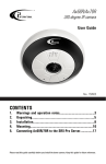
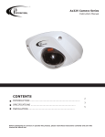
Ax61/Ax62-series
User Guide
(Ax61D2, Ax61D4, Ax61D8, Ax62D, Ax62V)
CONTENTS
1. Warnings and operation notes..........................................3
2.Unpacking....................................................................4
3.Installation.....................................................................6
4. Camera Adjustments........................................................12
5. Connecting your IP Camera to the SRX-Pro Server........14
6. Advanced Camera Setup..................................................22
7.Specifications.................................................................39
Please read this guide carefully before you install the dome camera. Keep this guide for future reference.
Ax61/Ax62-series User Guide
COPYRIGHT © 2013 by i3 International, Inc. All rights reserved.
No part of this manual may be reproduced or transmitted in any form or by any
means, electronic or mechanical, including but not limited to, photocopying,
recording, or by any information storage or retrieval system, without the prior
written permission of the copyright owner and the publisher.
Annexxus is a registered trademark of i3 International Inc.
Disclaimer
This quick start guide is provided as is, without warranty of any kind, expressed or
implied, including but not limited to performance, merchantability, or fitness for any
particular purpose. Neither i3 International Inc. nor its dealers or distributors shall be
liable to any person or entity with respect to any liability, loss, or damage, caused or
alleged to have been caused directly or indirectly by this information.
Furthermore, i3 International Inc. reserves the right to revise this publication, and to
make changes to the content at any time, without notice.
FCC
This device complies with part 15 of the FCC Rules. Operation is subject to the
following two conditions: (1) This device may not cause harmful interference, and (2)
this device must accept any interference received, including interference that may
cause undesired operation.
Address:
i3 International Inc.
780 Birchmount Road, Unit 16
Scarborough, ON M1K 5H4
Canada
Contact us:
Tech Support: 1.877.877.7241
Email. [email protected]
Web Site: www.i3international.com
Table of Contents
1. Warnings and operation notes
2. Product Overview
3.Unpacking
4.Installation
5. Connecting your IP Camera to the SRX-Pro Server
6. Advanced Camera
7.Specifications
2
i3-TRNG-CAMS-Ax61/Ax62.indd
Rev. 141202
1. Warnings and operation notes
Please read this guide carefully before you install the dome camera.
Keep this guide for future reference.
Thank you for purchasing an i3 Ax61/Ax62-series camera.
If the system needs to be modified or repaired, contact a certified i3 International
Dealer/Installer. When serviced by unauthorized technician, the system warranty
will be voided. Should you have any problems or questions regarding our products,
contact your local i3 International Dealer/Installer.
1.1 Precautions
Installation and serving should be performed only by qualified and
experienced technicians to conform to all local codes and to maintain
your warranty.
WARNING! To reduce the risk of fire or electric shock, do not
expose the product to rain or moisture.
When installing your Ax61/Ax62 camera be sure to avoid:
• excessive heat, such as direct sunlight or heating appliances
• contaminants such as dust and smoke
• strong magnetic fields
• sources of powerful electromagnetic radiation such as radios or TV transmitters
• moisture and humidity
• areas with mechanical vibrations
• fluorescent lamps or objects that reflect light
• unstable light sources as this may cause flickering
• temperatures below -10° Celsius or 14° Fahrenheit and above 50° Celsius or
122° Fahrenheit.
1.2 Power Supply
Ensure the supplied voltage meets the power consumption requirements of this
camera before powering the camera on. Incorrect voltage may cause irreparable
damage to the video camera and will effectively void the camera warranty.
PoE power is supported in the indoor (Ax61/Ax62D-series) and outdoor (Ax62V)
installations.
i3-TRNG-CAMS-Ax61/Ax62.indd
3
Rev. 141202
1.3 Cleaning
• For maximum optical clarity, the camera or lens must remain clean. Use a soft,
dry cloth to remove finger prints and dust from the dome cover.
• Use a blower to remove dust from the lens.
• Clean the body with a soft, dry cloth. If it is very dirty, use a cloth dampened
with a small quantity of neutral detergent, then wipe dry.
• Do not use volatile solvents such as alcohol, benzene, or thinners, as they may
damage the surface finish.
1.4 Servicing
To avoid electrical shock and to preserve the product warranty, DO NOT disassemble
the camera. Refer servicing to qualified personnel only.
2. Unpacking
Check that the items received match those listed on the order form and packing slip.
In addition to this manual and a fully assembled camera, the dome camera packing
box includes:
(All Ax61/Ax62 series)
1. User Manual CD x1
2. Guide Pattern sticker x1
3. Flush Mount template (the box lining) x1
4. Hex key x1
5. Plastic Anchor x4
6. Standard RJ45 Connector x1
7. Short RJ45 Connector x1
8. 2nd video monitor output BNC cable x1
(Ax61D/Ax62D series only)
9. Flat Head Screw (Tapping Type) x4
10.Flat Head Screw (Machine Type 26L) x3
11.Rubber plug x8
12.NPT 1/2” Rubber x1
13.NPT 3/4” Rubber x1
(Ax62V series only)
14.Round Head Screw
(Tapping Type) x4
15.O-rings x4
16.Rubber gasket x1
17.Desiccant in a package x1
If any parts are missing or damaged, contact the dealer you purchased the camera
from.
i3-TRNG-CAMS-Ax61/Ax62.indd
4
Rev. 141202
Accessories (not to scale)
All Ax61/Ax62 series
Lens Direction
User Guide
IP Finder
M
Note: Mounting surface material
determines screw type. Refer to manual.
GUIDE PATTERN
1
2
6
3
4
5
6
7
8
Ax61D/Ax62D series only
9
10
11
12
Ax62V series only
14
15
i3-TRNG-CAMS-Ax61/Ax62.indd
16
5
13
17
Rev. 141202
3. Installation
The dome camera is ideal for indoor (Ax61D/Ax62D) and outdoor installation (Ax62V)
in commercial and residential environment. With 3-axis mount support, it provides
flexible installation on a ceiling or wall even at an angle. The dome camera is a fully
integrated enclosure with camera and lens.
Note: The six holes on top of the Ax62V-series models are not drilled all the way
through for moisture control and the rubber corks are replaced with metal caps with
rubber washers.
3.1 Dimensions
137mm
130mm
63mm
63mm
84mm
a
1
b
c
d
Figure 3.1 Camera Parts
i3-TRNG-CAMS-Ax61/Ax62.indd
6
Rev. 141202
Figure 3-1
1. Camera dome, top view
a. Side conduit hole (1/2”).
When using outdoors (Ax62V only), sealant must be used to maintain the
IP67 status.
b. Top conduit hole (3/4”) (can also be used for pendant mount).
When using outdoors (Ax62V only), sealant must be used to maintain the
IP67 status.
c. PoE connector (Bottom case must be removed to reveal connector)
d. Video output connector (Bottom case must be removed to reveal
connector)
2. Bottom case
3. Camera base
4. Dome cover
5. Focus lever (Ax62-series only)
6. Zoom lever (Ax62-series only)
3.2 Routine Maintenance
• The dome cover is an optical part. Use a soft and dry cloth to remove any
fingerprints and dust.
• Clean the camera housing with a soft and dry cloth. For more stubborn marks,
use a cloth dampened with a small quantity of neutral detergent, then wipe dry.
• CAUTION: Do not use volatile solvents such as alcohol, benzene or
thinners, as they may damage the surface finish.
3.3 Disassembling the Camera
Before you mount and adjust the camera, follow these steps to disassemble the
camera.
1. Use a Hex key to remove the dome
cover.
Figure 3.2 Disassembling the camera
i3-TRNG-CAMS-Ax61/Ax62.indd
7
Rev. 141202
2. Loosen the 3 screws on camera base (#2).
1.
2.
3.
4.
5.
6.
Bottom case
Camera base
Tilt adjustment bracket
Inner liner
Dome cover
Anti drop hook
Figure 3.3 Disassembling the camera
3.4 Attaching the Desiccant (Ax62V models only)
1. Take the desiccant out of the package (#17 on Accessories list on page 5)
2. On the inside of the inner liner, peel the protective layer on the adhesive strip
revealing the adhesive surface. Attach the desiccant as shown in the diagram
below.
Figure 3.4 Attaching the desiccant to
Ax62V
i3-TRNG-CAMS-Ax61/Ax62.indd
8
Rev. 141202
3.5 Connecting the wiring
Follow Figure 3.1 to connect the video output connector (d), connect the PoE
connector (c).
3.6 Mounting the Camera
The following section explains how to install either a surface mount (3.5.1) or flush
mount. Select the mount appropriate to your application.
3.6.1 Surface mount
1. Attach the Guide Pattern Sticker to the wall or ceiling.
2. Drill four holes on the mounting surface and insert the plastic anchors (#1 in the
image below) into the holes.
3. Ax62V-series only: Complete drilling 4 holes on the base of the camera to match
the 4 holes drilled on the mounting surface.
(Recommendation: Surface conduit should point down to create a drip-loop.)
4. Ax62V-series only: After using it as a template for marking the mounting holes,
remove the protective film from the black rubber gasket and adhere to the base
of the outdoor model cameras.
5. Secure the bottom case to the wall or ceiling with the Flat Head Screws
(tapping type) (#2 in the image below).
For your convenience, the holes on the outdoor housing are started but not
drilled all the way through for moisture control.
Note: Depending on the material of your mounting surface, you may require
different screws and anchors than those supplied.
1. Plastic Anchors
2. Flat Head Screws
(Tapping Type)
Note: outdoor
screws come with
O-rings included.
Note: The Ax62V-series
cameras come with a
large rubber gasket to
provide the seal between
the mounting surface and
the camera base.
Figure 3.5 Camera Surface Mounting
i3-TRNG-CAMS-Ax61/Ax62.indd
9
Rev. 141202
3.6.2 Flush mount (Indoor installations only)
1. Prepare the mounting surface.
Use the Mounting Template (#3 on Accessories list on page 5) to cut a hole into
the mounting surface.
2. Remove the bottom case of the camera. (Refer to Figure 3.2 on page 7)
3. Insert camera into the hole
4. Turn screws (1) clockwise to adjust the wing tabs. Tighten the tabs securely
against the surface.
1. Wing Tab Adjustment Screws
(2 silver screws)
2. Wing Tabs
Figure 3.6 Camera Flush Mounting
i3-TRNG-CAMS-Ax61/Ax62.indd
10
Rev. 141202
3.6.3 Flush Mount Using Back Box
1. Prepare the mounting surface. Use the Mounting Template to cut a hole into
the mounting surface.
2. Remove the bottom case of the camera. (Refer to Figure 3.2) and attach to ¾”
NPT pipe (EMT or Rigid) ensuring the back box is flush with the T-bar tile.
3. Insert camera into the hole and attach anti drop hook cable if required. Secure
the bottom case to the wall or ceiling with the Flat Head Screws (tapping type).
4. Remove shorter black screws, fasten camera to back box with supplied longer
screws (#10 on Accessories list on page 5).
1. Wing tab adjustment screws
(silver screws)
2. Wing tabs
3. Three (3) longer back box
screws (black screws)
(#10 on Accessories list on
page 5).
2
3
1
3
1
3
Figure 3.7 Camera Flush Mounting using Back Box
i3-TRNG-CAMS-Ax61/Ax62.indd
11
Rev. 141202
4. Camera Adjustments
4.1 Adjusting the Camera Position
The dome camera has three axis for positioning the camera. While live viewing on
the monitor, adjust the camera position as follows:
• Horizontal adjustment rotates 3D assembly in the base.
• Vertical adjustment: After loosening the screw on the bracket, position the
camera as desired, and tighten the screw back to the bracket.
• Horizontal rotation for wall mount and tilted ceilings: rotate the lens base
(maximum 354°) until you are satisfied with the field of view.
1
2
3
4
5
Figure 3.8 Camera Adjustment
1. Rotate 3D assembly in base for horizontal adjustment
2. Loosen screw and adjust Tilt. Tighten screw when desired vertical angle is
achieved.
3. Turn axis ring for horizontal rotation.
4. Focus lever
5. Zoom lever
i3-TRNG-CAMS-Ax61/Ax62.indd
12
Rev. 141202
4.2 Adjusting the Lens
1. Loosen the focus lever (#4 on Fig. 3.8) counter-clockwise a little and adjust for
optimum picture sharpness.
2. Loosen the zoom lever (#5 on Fig. 3.8) counter-clockwise a little and rotate to
determine the image view.
3. Re-tighten the zoom lever and focus lever after adjustment.
Please note: It is important
that you lock the zoom and
focus levers after making
adjustments. This will avoid
the positions moving (for
example, from temperature
changes or vibrations).
4. Once all adjustments are
done, attach and secure the
2
camera housing:
a. Use a soft and lint-free
3
cloth to wipe the dome
cover and remove
fingerprints.
b. Attach the inner
liner (#3) to the tilt
4
adjustment bracket (#2).
Push down until it clicks
into place.
c. Assemble the dome
cover (#4) and the
Figure 3.9 Adjusting the lens
camera base (#1).
4.3 Camera Control Panel
1
Control Panel is located under the dome cover. Remove inner liner for easier access.
1. Service-BNC Video Output Selection Switch: Switch to “Service” for Service
Port video output; switch to “BNC” to
display video from the camera’s BNC
port. The default setting is “Service”.
2. Default: To reset all camera’s settings
to factory default, press and hold for 5
seconds.
3. Reset: Press to reboot the camera.
4. Service Video o/p: For monitor output.
Use the BNC cable provided with the
camera’s accessories.
i3-TRNG-CAMS-Ax61/Ax62.indd
13
Rev. 141202
5. Connecting your IP Camera to the SRX-Pro Server
5.1 Camera Connection Options
Connection Type 1:
Crossover direct connection
i3 SRX-Pro Server
Connection Type 2:
LAN
Via Gigabit Switch
i3 SRX-Pro Server
5.2 Hardware/Software Requirements
The following requirements must be met to achieve a successful network connection
with the Ax61/Ax62-series IP camera.
SRX-Pro Server:
• i3 SRX-Pro Version 3.0 or higher
• Latest GiPi adapter is installed. GiPi adapters can be downloaded from i3 FTP
website. (Please contact i3 Technical Support for more information.)
• Windows XP, XPe, 7 Pro or 7e
• Internet Explorer Version 8.0 or later
• CPU: Intel Pentium Core 2 or higher
• Memory: 1GB or more
• VGA card--supporting Direct X 9.0 or above
Power Supply
PoE power is supported in the indoor (Ax61/Ax62D-series) and outdoor (Ax62V)
installations.
Note: Camera damages resulted from improper power application are
NOT covered by the camera warranty.
i3-TRNG-CAMS-Ax61/Ax62.indd
14
Rev. 141202
Switch
A Gigabit Switch is required to monitor two or more cameras from the same
SRX-Pro Server.
5.3 Configuring Internet Explorer for Video Display
Your Internet Explorer (v.8.0 or higher) must first be configured in order to properly
display video stream from your Annexxus camera.
Follow these instructions to configure your Internet Explorer browser.
Enable Cookies
1. In Internet Explorer window, click Tools -> Internet Options
2. Open Privacy tab, move the slider to “Low” or “Accept All Cookies”
3. Click Apply. Do not close the Internet Options window.
Adjust Internet Security Settings
1. Open Security tab in the Internet Options window
2. If the camera operates inside of the Intranet, click the Intranet icon;
If the camera operates outside outside of the Intranet, click the Internet icon.
3. Click Custom Level. Security Settings - Internet Zone window will be
displayed.
4. Scroll down to the ActiveX controls and plug-ins radio buttons and
configure as follows:
»» Automatic prompting for ActiveX controls -> Enable
»» Download signed ActiveX controls -> Prompt (recommended)
»» Download unsigned ActiveX controls -> Prompt
»» Initialize and script ActiveX not marked as safe for scripting -> Prompt
»» Run ActiveX controls and plug-ins -> Enable
»» Script ActiveX controls marked safe for scripting -> Enable
5. Click OK to save the Internet Security Settings
6. Close all Microsoft Internet Explorer Windows and open a new IE window. This
will allow the new settings to take effect.
i3-TRNG-CAMS-Ax61/Ax62.indd
15
Rev. 141202
5.4 Using Annexxus Finder to assign IP Address to your IP Camera
Camera’s default IP address is 192.0.0.16
Camera’s default subnet mask address is 255.255.255.0.
Firmware Version
i3_00_026-40
i3_00_39-51, or higher
Default Login
admin
i3admin
Defaul Password
1234
i3admin
To connect your Annexxus camera to your SRX-Pro Server, follow these instructions:
1. Close SRX-Pro Server software by pressing Alt+Shift+Ctrl+F4.
2. Change the IP address on the onboard NIC (LAN) (or on NIC1 if your SRX-Pro
Server has two onboard NIC cards) of your SRX-Pro Server to 192.0.0.XXX to
match the default IP range of your Annexxus IP camera.
3. Connect the network cable from the SRX-Pro Server (crossover direct
connection) or from the Gigabit switch to your Annexxus camera.
4. Turn on your Annexxus camera.
5. Locate the CD that came with your Annexxus camera and insert it in the
CD-ROM drive of your SRX-Pro Server.
6. Double-click “AnnexxusFinder.exe” file to install Annexxus Finder application.
Annexxus Finder application discovers all Annexxus cameras connected to your
network.
7. Follow the Annexxus Finder installation instructions until the application has
been successfully installed on your SRX-Pro Server.
8. Double-click Annexxus Finder icon on the Desktop to launch the application.
The application window will appear displaying a list of active network cameras
9. Next, select desired camera in the Annexxus Finder software by double-clicking
it in the list and click Edit.
i3-TRNG-CAMS-Ax61/Ax62.indd
16
Rev. 141202
10. Enter the new IP address and Subnet Mask of the camera in the Change IP
Address area. The new camera IP address must match the original range
of your SRX-Pro LAN or NIC1 card. E.g. If your original SRX-Pro Server’s IP
address was 192.138.10.122, change your Annexxus camera’s IP address to
192.138.10.XXX.
Remember: Annexxus Cameras cannot share an IP address, each camera
requires its own unique IP address.
11. Enter the default camera password in the Input Password field and click Save
i3-TRNG-CAMS-Ax61/Ax62.indd
17
Rev. 141202
12. Wait a few moments as the new IP address is being applied to your Annexxus
camera. Wait for the following message to be displayed. Click OK to close it.
13. Repeat Steps 1-12 for all detected Annexxus cameras in the Annexxus Finder.
14. Now that the new IP address has been successfully assigned to your camera,
make sure you can connect to it through the Internet Explorer:
15. Launch Internet Explorer on your SRX-Pro Server and enter the IP Address you
have just assigned to your Annexxus camera. The password window should be
displayed.
16. Enter the default camera User Name and default Password and click OK.
Default Login/Password:
FW ver. i3_00_026-40
Login: admin / PW: 1234
FW ver. i3_00_39-51, or higher,
Login: i3admin
Password: i3admin
i3-TRNG-CAMS-Ax61/Ax62.indd
18
Rev. 141202
17. Annexxus camera interface will be displayed in the Internet Explorer window.
You should be able to see the camera image on the screen.
If you do not see the camera image on the screen, call i3 International tech
support for help.
5.5 Adding your IP Camera to your SRX-Pro Server
1. Make sure that the latest version of GiPi updater is installed on your SRX-Pro
Server. You can download the updates from
ftp://ftp.i3international.com/drivers/gipi
Please contact i3 Technical Support team for access information.
2. Once the latest GiPi updater has been installed, restart i3 SRX-Pro Server
software.
i3-TRNG-CAMS-Ax61/Ax62.indd
19
Rev. 141202
3. Log In and go to the Setup -> IP Camera tab.
4. Click the Search button to display connected Annexxus cameras.
i3-TRNG-CAMS-Ax61/Ax62.indd
20
Rev. 141202
5. Select the detected camera in the list and click Select.
6. In the Select IP Camera window, enter the default camera User Name and the
default Password, then click Add.
Default Login/Password:
FW ver. i3_00_026-40 | Login: admin / PW: 1234
FW ver. i3_00_39-51, or higher | Login: i3admin / PW: i3admin
7. The selected camera will be added to the IP Camera list.
Don’t forget to assign the IP camera to the SRX-Pro video channel in the Your
Annexxus camera is now connected to SRX-Pro Server and is ready to record.
You may change resolution and frame rate for the Annexxus camera in the
IP Camera tab menu or you may choose to configure the camera’s advanced
settings (see the following section).
i3-TRNG-CAMS-Ax61/Ax62.indd
21
Rev. 141202
6. Advanced Camera Setup
To access Annexxus camera’s advanced setup, go to Setup -> IP Camera tab, select
the camera in the list of added IP cameras and click the Advanced Setup button.
The password window will be displayed. Enter the default camera User Name
and the default Password. Camera’s user interface will be displayed in a separate
Internet Explorer window.
Default Login/Password:
FW ver. i3_00_026-40 | Login: admin / PW: 1234
FW ver. i3_00_39-51, or higher | Login: i3admin / PW: i3admin
i3-TRNG-CAMS-Ax61/Ax62.indd
22
Rev. 141202
In the main interface, you may adjust your camera’s
Brightness, Contrast, Saturation and Sharpness levels.
Click Save to save adjusted settings or
Default to set all settings back to 50%.
Note: This panel is enabled in the Live View mode only
and is disabled when in the Setup mode.
Next, click the Setup button to access Annexxus camera Setup features.
6.1 Basic Setup
You may switch to the advanced setup at any time by clicking the button in the
bottom left-hand corner. To switch back to the Basic Setup, click the same button
again.
Basic Setup is divided into Camera and Network settings.
After making any setting adjustments, remember to click the Save button
i3-TRNG-CAMS-Ax61/Ax62.indd
23
Rev. 141202
Camera Settings:
• Camera Name: The name of the camera will be displayed at the top of the
Internet browser page.
• Video Codec: Set the compression mode to MJPEG or H264
• Resolution: Set the resolution of the recorded video to D1, SVGA, 720P, SXVGA
1080P (full HD)-recommended, 2304x1296, or QXGA (2048x1536).
• Frame Rate: Set the frame rate for the recorded video to 1, 3, 7.5, 15, or 30
fps-recommended (unavailable with 2304 x 1296 and QXGA resolutions)
• Bit Rate (for H264 codec): Set the video bit rate from 50-8000 kbit/s
• H264 GOP (for H264 codec): Set the GOP rate from 1-60. The lower the
number, the lower the compression the larger the video size. The higher the
number, the higher the compression and the smaller the video size. GOP rate
determines the i-Frame frequency.
• H264 Rate Control Mode (for H264 codec): VBR (Variable Bit Rate) or CBR
(Constant Bit Rate).
»» VBR (Variable Bit Rate) (recommended): This setting will produce a variable
bit rate video stream, however the video quality will remain constant
resulting in high quality video images. Network infrastructure must be able
to provide the set bandwidth to account for bit rate variations.
»» CBR (Constant Bit Rate): This setting will produce a constant bit rate
video stream at the cost of video quality. The quality may deteriorate
considerably when motion is detected. This setting is beneficial for
installations with limited bandwidth.
• Quality (for MJPEG codec only): HIGH, MID, LOW
Network settings:
• DHCP: Enable or Disable to have the network automatically assign an IP address
to the camera.
• IP Address: Manually enter the camera’s IP address here.
This option should NOT be used if DHCP is enabled.
• Subnet Mask: Manually enter the camera’s Subnet Mask here.
This option should NOT be used if DHCP is enabled.
• Default Gateway: Provide the IP address of the network’s router if necessary.
Contact your network administrator for this information.
• DNS: Specify a DNS if necessary.
Contact your network administrator for this information.
• Physical Address: This is the camera’s unique MAC Address. It may not be
changed.
24
i3-TRNG-CAMS-Ax61/Ax62.indd
Rev. 141202
6.2 Video Setup
Switch to the Advanced Setup by clicking the Advance Setup button on the
bottom left-hand corner of the screen as shown on the previous page. The Setup
screen will change to reveal multiple setup tabs. Video Setup tab is displayed by
default.
Camera Settings:
• Camera Name: The name of the camera will be displayed at the top of the
Internet browser page.
• TV System: NTSC or PAL. To change the setting, access System setup tab.
• Mirror: Flips the video image. The options for mirror are:
»» OFF: Do not use this feature
»» FLIP: flip images vertically, upside-down.
»» MIRROR: flip images horizonrally, left to right.
»» BOTH: flip both horizontally and vertically.
Annexxus 61/62 camera series supports triple streaming, where Primary Streaming
is the default stream used for video recording and Third Streaming is used for Live
Viewing. Each stream can be configured separately.
i3-TRNG-CAMS-Ax61/Ax62.indd
25
Rev. 141202
Note: Enabling Streams 2 and 3 may cause frames being dropped on
Stream 1.
Configure Stream 1 - Primary Streaming (Recorded Video):
• Video Codec: Set the compression mode to H264 or MJPEG
• Resolution: Set the resolution of the recorded video to one of the following:
»» D1 (720×480)
»» SVGA (800×600)
»» 720P (1280×720)
»» SXGA (1280×960)
»» 1080P (1920×1080 - full HD) - recommended
»» 2304 x 1296
»» QXGA (2048 x 1536)
Note that when the Resolution on the Primary Streaming is set to QXGA or
2304 x 1296, and Third streaming will be disabled. When the Resolution on
the Primary Streaming is set to 1080P, Third streaming is disabled.
• Frame Rate: Set the frame rate for the recorded video to 1, 3, 7.5, 10, 15
(available only with 1080P resolution), or 30 fps - recommended (unavailable
with 1080P resolution)
• Bit Rate (for H264 codec): Set the video bit rate from 50-8000 kbit/s
• H264 GOP (for H264 codec): Set the GOP rate from 1-60. The lower the
number, the lower the compression the larger the video size. The higher the
number, the higher the compression and the smaller the video size. GOP rate
determines the i-Frame frequency.
• H264 Rate Control Mode (for H264 codec): VBR (Variable Bit Rate) or CBR
(Constant Bit Rate). See p. 24 for details.
• Quality (for MJPEG codec only): HIGH, MID, LOW
Configure Stream 2 - Secondary Streaming:
Note: Unavailable with 2304x1296 and QXGA resolutions.
• Video Codec: Set the compression mode to H264 or MJPEG
• Resolution: Set the resolution. The list of available resolutions will depend on
the resolution of the Primary Streaming. Set the Resolution to “None” to disable
Secondary Streaming.
• Frame Rate: Set the frame rate for the recorded video to 1, 3, 7.5, 15 or 30 fps
• Bit Rate (for H264 codec): Set the video bit rate from 50-8000 kbit/s
• H264 GOP (for H264 codec): Set the GOP rate from 1-60. (Same as Primary)
• H264 Rate Control Mode (for H264 codec): VBR (Variable Bit Rate) or CBR
(Constant Bit Rate). See p. 24 for details.
• Quality (for MJPEG codec only): HIGH, MID, LOW
26
i3-TRNG-CAMS-Ax61/Ax62.indd
Rev. 141202
Configure Stream 3 - Third Streaming (Live View):
Note: Unavailable with 1080P, 2304x1296 and QXGA resolutions.
• Video Codec: Set the compression mode to H264 or MJPEG
• Resolution: Set the resolution. The list of available resolutions will depend on
the resolution of the Primary and Secondary Streaming. Set the Resolution to
“None” to disable Third Streaming.
• Frame Rate: Set the frame rate for the recorded video to 1, 3, 7.5, 15 or 30 fps
• Bit Rate (for H264 codec): Set the video bit rate from 50-8000 kbit/s
• H264 GOP (for H264 codec): Set the GOP rate from 1-60. (Same as Primary)
• H264 Rate Control Mode (for H264 codec): VBR (Variable Bit Rate) or CBR
(Constant Bit Rate). See p. 24 for details.
• Quality (for MJPEG codec only): HIGH, MID, LOW
Advance Settings:
• White Balance: Set White Balance mode to Auto or Manual according to the
image’s lighting conditions for the best color temperature.
• R Gain, G Gain, B Gain (Use when White Balance is set to Manual):
Adjust levels of red, green and blue in the image.
Values can be set from 0-255
• Brightness: adjust the image brightness level, Values range from 0% to 100%.
• Contrast: adjust the image contrast level. Values range from 0% to 100%.
• Saturation: adjust the image saturation level. Values range from 0% to 100%.
• Sharpness: adjust the image sharpness level. Values range from 0 to 15.
• Hue: adjust the image hue. Values range from 0 to 15.
After making any setting adjustments, remember to click the Save button
to save any changes made.
i3-TRNG-CAMS-Ax61/Ax62.indd
27
Rev. 141202
6.3 Alarm/Motion (optional)
• Motion Detection: Enable or Disable Motion Detection
• Sensitivity: When Enabled, set the Motion Sensitivity to HIGH, MEDIUM, LOW
• Set Motion. Wait for the static image, then click Set Motion button. Any change
to the current static image will be recognized as motion.
6.4 Privacy Zone (optional)
In the Privacy Zone setup tab, select an area that needs to be blocked off with
a rectangle on Live View and from video recording because of privacy or other
concerns. Up to 5 separate Privacy Zones can be configured.
Color Setting: Select between BLACK, GREY and WHITE to determine what color
will be used to block out the configured privacy zone.
i3-TRNG-CAMS-Ax61/Ax62.indd
28
Rev. 141202
To draw the privacy zone, follow these instructions:
1. Set the Privacy Zone Enable to ON to activate a privacy zone.
2. Position your mouse cursor over the Preview window, press and hold the left
mouse button.
3. While holding down the left mouse button, drag the cursor to draw a
rectangular area over the zone that needs to be concealed.
4. Release the mouse button. The privacy area rectangle will be shaded blue in the
Preview window.
5. If you are not satisfied with the size or positioning of the privacy zone, repeat
steps 2-4 to re-draw it.
6. Click the Apply button
7. Repeat Steps 1-6 for additional Privacy Zones, if using.
After making any setting adjustments, remember to click the Save button
to save any changes made.
6.5 Exposure
Set the exposure level for your camera. Exposure time determines how much light
passes through the camera aperture to the focus.
i3-TRNG-CAMS-Ax61/Ax62.indd
29
Rev. 141202
Auto Exposure: Select this option to correct the exposure automatically.
• Exposure Mode: Set exposure mode to AES, ALC (Ax62D only) or Flickerless
(Ax62D only).
• Slow Shutter: Set the shutter speed. Acceptable value range is from 1/30 to
1/3.75 sec. Select OFF to disable the feature.
• Max Gain: Set the maximum gain value. The higher value will enhance the video
signal. Note that the noise will also be enhanced. Values range from 24 to 36.
Manual Exposure: Select this option to correct the exposure manually.
• Shutter Speed: Set the shutter speed. Acceptable value range is from 1/8000 to
1/60 sec.
• Manual Gain: Set the Manual Gain value. The values range from 0 to 36
Exposure Misc:
• EV: Set exposure value between -2 and 2. Higher values produce brighter
images.
• Day Night: Set the Day/Night setting to AUTO, COLOR or BW
• Noise Reduction: Set the Noise Reduction value. The values range from 0 to
255.
• BLC: When parts of the environment are poorly lit, BLC can be configured to
compensate for inadequate lighting conditions. To configure the individual areas
that will receive compensation, select one of the available options: UPPER 2
3rds, LOWER 2 3rds, CENTER 1 3rd, CENTER 1 6th, LEFT, RIGHT, or FULL.
Enabled areas will be shaded in the Preview screen.
• WDR: Set the Wide Dynamic Range Level if desired. The WDR can be turned
OFF, or set to HIGH, MIDDLE or LOW.
• Gamma Correction: Gamma Correction can be set to 0.45 or to 1.
• Reset Exposure: Click this button to restore camera default exposure values.
After making any setting adjustments, remember to click the Save button
to save any changes made.
i3-TRNG-CAMS-Ax61/Ax62.indd
30
Rev. 141202
6.6 Network Recording
Under Network Recording tab, Ax61/62 series camera can be configured to send out
an email alert every time motion is detected. It can also record video to a configured
FTP server based on motion or on pre-set schedule.
Note: Only MJPEG video streams can be used with SMTP & FTP recording options.
To set the video stream to MJPEG Video Codec, see Video setup tab.
SMTP Server:
• SMTP Record Condition: Set to MOTION to enable this setting.
• SMTP Server: Enter the SMTP Email Server address
• Login ID: Enter your SMTP Email Server login
• Password: Enter your SMTP Email Server password
• Sender Email Address: Enter your email address
• Port: Enter the SMTP Server port
• Authentication: Select the SMTP Server’s authentication type from NO
AUTHENTICATION, SMTP PLAIN, LOGIN and TLS-TTLS
i3-TRNG-CAMS-Ax61/Ax62.indd
31
Rev. 141202
Condition Settings for Sending E-mail by Motion:
• Subject: Enter the email subject
• Message: Enter the body of the email message
• Attach Image: Set to ON to attach a snapshot to the motion-triggered email
Email Address List:
• Configure up to three separate email reciepients. Set Enable and Motion
settings to ON and enter the email address for each of the reciepients in the
corresponding field.
FTP Server:
• FTP Record Conditions: To enable, set to MOTION or SCHEDULED
• FTP Server: Enter the FTP Server address
• Login ID: Enter the FTP Server login
• Password: Enter the FTP Server Password
• FTP Port: Enter the FTP Port
Scheduled Recording Table:
• Set the recording schedule type for each day of the week: OFF (to disable), ALL
DAY, SCHEDULE 1 or SCHEDULE 2. Schedules 1 and 2 are configured directly
below.
Scheduled Recording Settings:
• Schedule 1 and Schedule 2: Set the Start Time and End Time for your custom
recording schedules.
• Recording Cycle: Set the length of the video clip. Values range between 2
seconds and 120 seconds (2 minutes)
• File Name: Set the default video file name
• Server Path: Set the FTP Server path, where the video recordings will be
stored.
Motion Recording Settings:
i3-TRNG-CAMS-Ax61/Ax62.indd
32
Rev. 141202
• Motion Recording Cycle: Set the video recording length (in sec) preceeding the
triggered motion. Values range between 1 and 30 seconds.
• Pre Recording Frame: Set the video frame rate for the video preceeding the
triggered motion. Values range between 1 and 10 frames per second.
• Recording Cycle: Set the video recording length (in sec) that immediately
follows the triggered motion. Values range between 2 seconds and 120 seconds
(2 minutes)
• Recording Frame: Set the video frame rate for the video that immediately
follows the triggered motion. Values range between 1 and 60 frames per
second.
• File Name: Set the default video file name
• Server Path: Set the FTP Server path, where the video recordings will be
stored.
After making any setting adjustments, remember to click the Save button
to save any changes made.
6.7 Communication Setup
The Communication tab is used to configure network and communication settings on
the camera.
i3-TRNG-CAMS-Ax61/Ax62.indd
33
Rev. 141202
Network settings:
• DHCP: Enable or Disable to have the network automatically assign an IP address
to the camera.
• IP Address: Manually enter the camera’s IP address here.
This option should NOT be used if DHCP is enabled.
• Subnet Mask: Manually enter the camera’s Subnet Mask here.
This option should NOT be used if DHCP is enabled.
• Default Gateway: Provide the IP address of the network’s router if necessary.
Contact your network administrator for this information.
• DNS: Specify a DNS if necessary.
Contact your network administrator for this information.
• HTTP Port: Use the default Port 80 if possible. Contact your network
administrator if the setting needs to be changed.
• Physical Address: This is the camera’s unique MAC Address. It may not be
changed.
OSD Settings:
• OSD Camera Name: Can be set to ON or OFF
• OSD Date Time: Can be set to ON or OFF
RTSP Settings:
• This area can be configured to allow users get the video stream using third party
players, such as VLC with the help or RTSP protocol.
After making any setting adjustments, remember to click the Save button
to save any changes made.
i3-TRNG-CAMS-Ax61/Ax62.indd
34
Rev. 141202
6.8 User Management
User Management tab displays the list of users that have access to the Annexxus
camera. The username and password from this setup tab are used when connecting
the camera to SRX-Pro Server.
Reminder: Whenever a change is made to the Annexxus camera user in the
camera’s Advanced Setup -> User Management tab, remember to update this
information in the IP Setup tab of the SRX-Pro Server.
Two types of user permissions exist: Aministrator and Viewer. Administrator
users have access to the camera’s setup settings, while Viewer may only view
camera live stream. Each camera has one master Administrator user (admin/i3admin)
and five additional users that can be assigned either Administrator or Viewer
priviliges.
Note: The accounts may not be deleted but the passwords and user names can be
changed.
6.8.1 Modifying User Accounts
To change the password, user name or permissions type for one of the user
accounts, follow instructions below:
1. Select user account in the User List on the left hand side.
2. To change user name, enter new user name in the New Username field in the
Modify User area.
3. To change the account password, enter the new password in the Password field
and Confirm Password fields of the Modify User area.
4. To change permission type, select either Administrator or Viewer in the
Permission drop-down menu.
5. Click Update User button to apply changes.
6. Click OK in the confirmation message.
i3-TRNG-CAMS-Ax61/Ax62.indd
35
Rev. 141202
6.9 System Setup
In this section, you can configure basic camera system settings.
• Date & Time: Displays the camera’s current date and time
• Date formats include: YYYY/MM/DD, MM/DD/YYYY and DD/MM/YYYY.
• New Date & Time: You may choose to...
»» Set the Date and Time Manually
»» Synchronize Date & Time with Computer Time or
»» Synchronize Date & Time with NTP Server. NTP Server and Time Zone
can be configured in the Communication Setup tab. See section 6.3 for
details.
System Information:
This section contains information on the Camera’s Model Name and Firmware
version. Change the Camera TV System between NTSC and PAL if it currently
doesn’t match your local standard.
Update Firmware:
All Annexxus-series cameras are sold with the most recent version of the firmware
already installed. If in the future firmware updates are released, you can update your
camera’s firmware by first downloading the firmware file from i3 International’s
website or FTP site. After downloading firmware file, click the Browse... button
in the camera’s System setup tab and locate the new firmware file. Then click the
Update button and wait while the firmware is being updated on your camera.
Note: Be sure to stop all camera operations prior to an update. Do not turn off
power or disconnect from the network during the process.
Click Restart Camera after you have updated firmware successfully.
i3-TRNG-CAMS-Ax61/Ax62.indd
36
Rev. 141202
Restart/Reset:
• Click Restart Camera to restart your Annexxus-series camera. This will
cause a temporary disconnect, no video will be recorded while the camera is
restarting but all custom settings will be saved. Camera restart is required after
the firmware update. After clicking, a pop up will appear asking you to confirm.
Click Yes.
• Click Factory Reset to return all settings, except for the Networking (IP)
settings to factory defaults. After clicking, a pop up will appear asking you to
confirm. Click Yes.
• Click Hard Factory Reset to return all camera settings, including IP address,
to factory defaults. After clicking, a pop up will appear asking you to confirm.
Click Yes.
Note: Your Network Camera’s default IP address is 192.0.0.16 and the
default subnet mask address is 255.255.255.0.
Export Configuration:
• Click Export File to export your camera’s settings. If you have multiple
cameras of the same model and you would like to apply a set of customer
settings to each one, exporting the configuration file may save time.
• Click Browse to locate a configuration file to apply new settings to your
camera and click Import File.
After making any setting adjustments, remember to click the Save button
to save any changes made.
i3-TRNG-CAMS-Ax61/Ax62.indd
37
Rev. 141202
6.10 Logs
Logs setup tab displays all login and Alarms log records.
i3-TRNG-CAMS-Ax61/Ax62.indd
38
Rev. 141202
i3-TRNG-CAMS-Ax61/Ax62.indd
Lens
Resolutions
Maximum Framerate vs Resolution
Features/Model
Image System
Image Sensor
Video Streaming and Compression Method
7. Specifications
The specifications are subjects to be change without notice
Image Enhancements
Minimum Illumination
S/N ratio
Gain control
White balance
Shutter Time
Day/Night Mode
Auto Iris Control
Electric
View Angle
39
Rev. 141202
Ax62D
Ax62V
F:1.2, CL: 0.4 lux / BW: 0.2 lux @ 50 IRE
50dB (AGC off)
Off/ On, selectable
ATW(2800K~8500K) /Manual
Backlight Compensation: Off / On (6 Area selectable); Exposure Mode: Auto/Manual; Sharpness, Saturation,
Brightness, Contrast, Hue; Noise Reduction; WDR: Digital WDR. Off/High/Mid/Low; Digital Noise Reduction: 3D
0.25Lux / 0.2Lux / 0.2Lux
1/30~ 1/8000 sec. (NTSC); 1/25 ~ 1/8000 sec. (PAL)
CMOS 1/3” AR0330
Triple Streaming: H.264 / Motion JPEG
NTSC : 1080P (1920x1080) @ 30 fps ; 3M (2048x1536) @ 15 fps
PAL : 1080P (1920x1080) @ 25 fps ; 3M (2048x1536) @ 12 fps
QXGA(2048x1536), 2304x1296,
1080P(1920x1080), SXGA(1280x960), 720P(1280x720), SVGA(800x600), VGA(640x480),
D1(NTSC:720x480 / PAL:720x576),
4CIF(NTSC: 704x480 / PAL: 704x576),
CIF(NTSC: 352x240 / PAL: 352x288)
Built-in fixed lens
F2.0, f=2.8mm/ F1.8, f=4.2mm/
F1.2~2.1, f=3~9mm
F1.8, f=8.0mm
V:58°, H:104°/ V:38°, H:71°/ V:20°,
V: 19° (Tele) ~ 52° (Wide) / H: 33° (Tele) ~ 96° (Wide)
H:36°
Digital D/N
Mechanical ICR
N/A
DC Iris
Ax61D2/4/8
i3-TRNG-CAMS-Ax61/Ax62.indd
40
Rev. 141202
Power Supply
Power Requirement
Power Consumption (max.)
Environment
Operating temperature
Operating humidity
Storage temperature
Storage humidity
Regulations, Ratings
Video Port/Output
Connectors
Other Features
Privacy Zone
Gamma correction
Motion Detection
Image Orientation
Other
Network Specifications
Network protocols
Security Access
Web browsing requirements
Mechanism
Dimensions
Weight
7. Specifications (cont.)
CE/FCC Class B, ONVIF
-10ºC ~ 50ºC (14ºF ~122ºF )
10~ 90% RH
-20ºC ~ 60ºC (-4ºF ~ 140 ºF)
90%, non-condensing
CE/FCC Class B, ONVIF
PoE IEEE 802.3af Class 0
7.0W
CE/FCC Class B, ONVIF, IP67
ø140 mm x 132 mm (ø5½” x 5¼”)
approx. 632g (1.39 lb)
approx. 1074g (2.36 lb)
Network: RJ45 (Female) w/ Network LED indicator; Buttons: Reset, Default (On top); Video output Switch (On
Top)
1 x Inside Service Port with 2 pin connector, 1.0Vp-p, 75Ω
1 x BNC Output, 1.0Vp-p, 75Ω
IPv4, HTTP/HTTPS, TCP, RTSP/RTCP/RTP, ICMP, UDP, IGMP, DNS, DHCP, ARP, NTP, SNMP, UPnP, SMTP
Two user access levels with password protection. 1 Administrator, 5 Viewers
Internet Explorer 8.0 or above
Yes
0.45
Yes
Mirror, Flip
System Log, FTP Record, Email Notification, User Management
i3 INTERNATIONAL INC.
1.866.840.0004
www.i3international.com
U.S.A. 1967 Wehrle Drive,
Suite 1, PMB# 034 Buffalo
NY, 14221
Canada 780 Birchmount Road,
Unit 16, Scarborough,
ON, M1K 5H4