1
Peavey
PC1600X
1
Peavey PC1600X User Manual (rev-h)
2
Peavey PC1600X User Manual (rev-h)
CAUTION: Risk of electrical shock DO NOT OPEN!
CAUTION: To reduce the risk of electric shock. Do NOT REMOVE COVER.
No user serviceable parts inside.
Refer servicing to classified service personnel.
WARNING: To prevent electrical shock or fire hazard, do not expose this
appliance to rain or moisture.
Before using this appliance read the operating guide for further warnings.
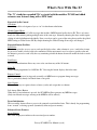
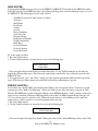
PC1600X Firmware Versions
Version
Had some small fixes over 2.0
2.1
2.2
2.3
Not documented as well as latter ones, so you
might want to update if you have 2.0
Not just Roland checksums
Yamaha-style checksums supported in SysEx
strings
Added a version request message so computer Fixed the scene receive MIDI message to take all
editors could "ask" the unit which software
100 scenes, not just the first 50. It also fixed the
version it has
MIDI maps to be able to point to all the scenes.
NOTE: most users don't need anything past 2.1
Introduction
-----------------------------------------------------------------------------3
Peavey PC1600X User Manual (rev-h)
Congratulation on your purchase of the PC1600X MIDI Control Station This is THE MIDI command station
for digital workstations, sequencer control or remote MIDI editing. As a matter of fact the PC1600x will edit
and control just about ANY MIDI device. Fifty factory presets give a good representation of its power and
all fifty are completely user-programmable MIDI data is transmitted using the following controllers:
1. Sixteen programmable 60mm faders: Which can be assigned to transmit continuous controller
data like, volume, pan or any MIDI String (i.e. Channel System Messages). Also any fader can be the
master over any of the other faders. To simplify operation each fader can be individually named.
2. Sixteen programmable buttons: which can be assigned as: fader mute, fader solo, program
change, note on/off, MIDI string, MIDI string with button press & release (2 messages), MIDI string
toggle (2 messages), fader send, scene send and fader identify. Like the faders each button can be
named. Also buttons can be accessed remotely via Note or Program Change messages.
3. Data wheel: The “Data Wheel' can be linked to a fader or Control Voltage input and duplicate it’s
Programming. It can also transmit the value of the last fader moved.
4. Two Control Voltage Pedal Inputs: The 1600x allows you to plug in and assign CV pedals.
These are assigned like the faders. The CV 2 jack can also sub as a dual footswitch input.
The PC1600x has even more “under the hood!”
100 scenes: Just in case there comes a time when you would like to save your fader's physical position. (like
when mixing). the PC1600x offers 100 scenes that can be saved and recalled as needed. This feature is
extremely useful for MIDI light controllers, MIDI mixing, MIDI controllers, etc.
Three Merge Modes: When MIDI connections place the PC1600x between the source of data (sequencer,
etc), and the destination (tone modules. etc) it can merge with controller data coming into it in a variety of
ways.
Three modes are available:
1… Merge - Fader movements are merged with incoming data.
2… Replace - Same as above, except that when the fader is moved, incoming data is filtered and
replaced by data generated by the fader. Fader position determines the value transmitted
3… Update - When the fader is moved. its data matches the last value of the incoming data
regardless of fader position. This allows seamless modification of the incoming data.
MIDI Filtering: The PC1600x contains an extensive MIDI filtering section.
Programmable Set-up string: Along with all of the faders, buttons settings a MIDI Set-up string can be
transmitted when a preset is selected. This string can send Bank select, Program Change and Volume settings
for ALL 16 channels. In addition a scene and a MIDI string of up to 80 bytes can be sent.
Easy Synth Programming: The PC1600x will accept presets Pre-programmed for editing. We've made this
as “Painless as possible, by designing specific presets for the PC1600x that are stored in the Spectrum Synth,
Spectrum Organ and Spectrum Bass LL. You simply transfer them to the PC1600x. and you instantly have
fader and button control over all the parameters. Now, without ever having to deal with hexadecimal SysEx
messages you can edit presets quickly and spend more time getting work done.
4
Peavey PC1600X User Manual (rev-h)
The PC1600x will revolutionize your MIDI set-up Hook it up to your computer keyboard or other MIDI
device and take your music to another level.
5
Peavey PC1600X User Manual (rev-h)
Contents
---------------------------------------------------------------------What’s New With The “X”
9
Front Panel Description
12
Back Panel Description
14
---------------------------------------------------------------------------------------------------Fast Start
15
Connection
Overview
Changing Presets sending Current Values
Resetting Replace/Update Mode
Interface 101
Utility Menu
18
Navigation
View angle and MIDI Channel
MIDI Filter
Preset Mapping
Program Change Enable and Current map Status
Dumping Internal Data
Footswitch Assignments
Device Number and Note recording Receive Channel
MIDI Transmission delay
Remote Button Set-up
Individual Preset Initialization
Memory usage
Scenes
24
About Scenes
Sending A Scene storing A Scene
Scene Reset/initialization
Preset setup string Scene editing
About Presets and Editing
26
Initialization/Reset
Unit
Preset
Edit Introduction
Naming and Saving A Preset
Exiting Edit Mode Accessing Global setting with Special MIDI messages
6
Peavey PC1600X User Manual (rev-h)
Contents
---------------------------------------------------------------------Editing The Faders
29
Defining and Naming
No Message
Continuous Controller
Master Fader/CV
MIDI strings
Dealing with Checksum Values
Assigning String Device IDS and MIDI Channels to Global settings
Learn Mode
Saving Your Edits
Editing The Buttons
34
Defining and Naming
Off/Fader ID (No message)
Mute/Solo Fader
Program Change
Note On/Off
MIDI Strings
String Prs/Rls
String Toggle
Assigning String Device IDs And MIDI Channels To Global Settings
Responding To Remote Velocity Messages
Learn Mode
Send Fader
Note Stream Recording
Send Scene
Saving Your Edits
Editing The CV Pedals, Footswitches and Data Wheel
42
CV 1 & CV 2
What Type Of Control Voltage Pedal
Footswitch (see Utility section for more information)
Data Wheel
Defining The Preset Setup String
Bank/Program Change/Volume
About Bank Select
Scene Recall
MIDI String
Learn Mode
7
Peavey PC1600X User Manual (rev-h)
43
Contents
---------------------------------------------------------------------Copy Menu
45
Copying From The Main Menu
Copying From The Edit Menu
Appendix A: System Exclusive Messages
Appendix B: Parameter Formats
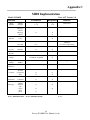
Appendix C: MIDI Implementation Chart
Appendix D: MIDI Controller Listing
Appendix E: Taking The Vex Out OF HEX
Appendix F: MIDI 101
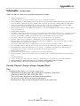
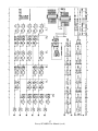
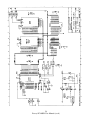
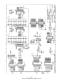
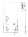
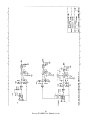
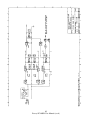
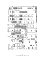
Appendix G: Schematic
8
Peavey PC1600X User Manual (rev-h)
46
47
49
50
51
54
56
What's New With The X?
---------------------------------------------------------------------The “X” stands for expanded! We've started with the modular PC1600 and added
extensive new features along with a NEW look!
Expanded SysEx Control
Checksum
Now it is possible to designate a byte as “cs” for checksum calculations.
Global Channel Bytes
Many MIDI products use SysEx messages that include a MIDI channel and/or device ID. This is of course
handy for differentiating among multiple units of the same type. Normally chancing this byte would require
editing of each fader/button individually. Now a new byte can be a part of the string that specifies the global
MIDI setting or Global device ID. By simple chancing the Global Setting all messages are changed.
Expanded Button Facilities
Send Fader
This feature provides an easy way to send specific fader values, when a button is set to “send faders it must
be pressed to enable a fader value to be transmitted. Fader movement is used to select a specific value and
the button is pressed to send it. By the way continuing to hold the button down will enable the fader to work
as usual.
Send Scene
This new button function allows any scene to be sent from any of the 16 buttons.
Fader ID
With a button programmed to “Off/Fader ID.” Dressing the button displays the fader name.
Remote Control
A1I 16 buttons can now be triggered externally via MIDI notes or program change messages.
This is particularly handy for control from a foot pedal.
Note Capture
This makes it easy to capture clusters of notes (cords) and assign then to a button.
Left Arrow (Mute) Button
When the Let Arrow button is pressed, the PC1600X will not generate any MIDI messages.
(Only non-filtered messages arriving at the MIDI In will be echoed).
Preset Initialization
This new utility feature allows a preset to be returned to an initialized state. This is handy for programming
from “scratch” or freeing up more dynamically allocated preset memory.
Enhanced Scene Features
Preset Identity
The scene display now indicates the associated preset number.
9
Peavey PC1600X User Manual (rev-h)
Scene Initialization
This new scene function allows an existing scene to be initialized, which dissociates it with any preset.
Setup String Additions
Scenes
A scene can now be assigned to each preset. Any time the preset is recalled, the scene will be transmitted.
Flexible Bank Select
Bank Select editing is now expanded to include MSB or LSB programming.
New factory Presets
Fifty presets are available that present a wide range of applications.
10
Peavey PC1600X User Manual (rev-h)
11
Peavey PC1600X User Manual (rev-h)
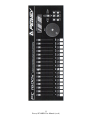
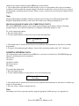
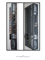
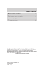
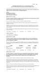
Front Panel
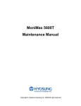
-----------------------------------------------------------------------------1. 16 Faders:
Each of the programmable faders can be assigned the following functions: No Message, Continuous
Controller, Master fader, MIDI string.
2. 16 Buttons:
Each of the programmable buttons can be assigned the following functions: Fader ID, Fader Mute,
Fader Solo, Program Change, Note-on/Note-off, MIDI String, MIDI String, Press and Release, MIDI String
Toggle, Send Fader, Send Scene.
3. Data Wheel:
This is a high-resolution device, which allows fine adjustment of any fader or control voltage value. The data
wheel can be linked to a fader or Control Voltage input and duplicate its programming. It can also transmit
the value of the last fader moved.
4. Display Window:
This is a 20 character by 2 line, Liquid Crystal Display (LCD) with adjustable contrast.
5. Direction Buttons:
The Up, Down, Left, Right direction buttons are used to navigate through the user interface. The Up/Down
buttons also serve as increment and decrement buttons to edit parameter values and chance presets. The left
arrow button also doubles as a MIDI mute button.
6. Edit Button:
This button accesses all parameters stored within a preset.
7. Utility Button:
This accesses all global functions of the PC1600X.
8. Copy Button:
The Copy button is used to copy from one preset or scene to another. It is also used to copy individual
messages.
9. Scene Button:
Scenes are “snapshots” of the current fader and CV values. in addition to the current preset number.
This button is used to save, store and initialize.
10. Enter button:
This button is used to execute functions whenever “Enter” appears in the Upper or Lower right hand corner
of the display. When the main page is displayed, pressing this button sends the current message for each
fader and CV input. The display will read “Sending Faders/CV’s.”
11. Exit button:
This button is used to escape from any menu. Pressing Exit several times will always return you to the main
page. Pressing Exit from the main menu page can reset the controller filtering of the update/replace merge
modes. The display will read “Replace/update reset.
12
Peavey PC1600X User Manual (rev-h)
13
Peavey PC1600X User Manual (rev-h)
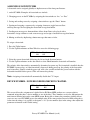
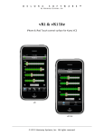
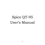
Back Panel
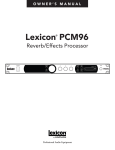
-----------------------------------------------------------------------------1. Power Supply Input:
Use only the 16 (VAC) 1000ma adapter provided. (Peavey part#: 709006601)
Caution: Use only the 16VAC Power Supply provided with this product. If the original Power
Supply must be replaced, consult your Peavey dealer or the factor for the correct replacement. Failure
to use the correct Power Supply could result in fire, shock hazard, extensive circuit damage,
decreased performance, non-operation loss of gigs, frustration, cursing, marital problems and an allaround bad day.
2. Power Switch:
Turns the PC1600X On and Off.
3. CV 2 / Footswitch 1 & 2:
This input accepts a control voltage foot pedal in addition to a single or dual footswitch. The foot
pedal is programmable per-preset and functions the same as a fader. Each footswitch can be assigned
to one of the following functions: up (Inc.), down (Dec.), “Enter” or duplication of a button (1-16)
Polarity is automatically detected at Power-On.
4. CV 1:
This input accepts a control voltage foot pedal and is programmable to function the same as a fader.
5. MIDI OUT:
This transmits all data generated internally. This also acts as a MIDI THRU for all unfiltered
messages received by the PC1600X.
6. MIDI IN:
This accepts commands to be interpreted by the PC1600x. It also accepts data to be echoed to the
MIDI OUT back.
14
Peavey PC1600X User Manual (rev-h)
Fast Start
---------------------------------------------------------------------This section is designed to set you up and running quickly.
Connection:
The PC1600X MIDI command station is ideal for digital workstations. sequencer control or remote MIDI
editing. Your specific application will dictate the proper MIDI connection.
The PC1600x is connected one of three ways:
Directly to a Device
Between Devices
Two-Way
15
Peavey PC1600X User Manual (rev-h)
Overview
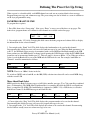
-----------------------------------------------------------------------------Overview
The display shown below is an example of the main display of the PC1600X. Pressing the EXIT button
several times will return to this page from any menu. Information shown on this page includes the current
preset number. Current preset name and information about the last fader or button moved.
00 Volume with mute
Fdr01=C1
Changing presets:
The PC1600x has 50 presets numbered 0-49. The current preset can be chanced using the Up/Down buttons
or by an incoming program change when a MIDI map is enabled. A footswitch assigned to duplicate the
Up/Down buttons can also be used to change presets while on this page. Lastly a system exclusive message
can be used to change presets (see Appendix A).
Sending current values:
Pressing the “Enter” button while on the main page will send the current message for each fader and CV
input. The display will read “Sending Faders/CVs”. This allows the PC1600X to cancel a soloed fader or
update external devices.
An Example:
Suppose the current preset is programmed to send MIDI volumes on each channel and the PC1600X is
connected to a sequencer. Pressing “Enter” from the main page at the start of a sequence allows all initial
volumes of the sequence to be recorded. Simple set the position of all defined faders start the sequencer
recording, then press “Enter” All following fader movements will track smoothly from this initial setting.
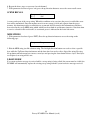
Resetting Replace or Update more with the EXIT button:
A fader defined as a continuous controller can be out in a mode that allows it to replace or update a matching
controller message passing through the PC1600x. As soon as the fader moves and sends its message, the
PC1600X begins filtering matching incoming messages. Press the Exit button from the main display page to
cancel this filtering allowing the incoming message to pass through the PC1600X. The display will confirm
this operation with “Replace/Update Reset” See page 21 for more information on this feature.
16
Peavey PC1600X User Manual (rev-h)
Interface 101
-----------------------------------------------------------------------------INTERFACE 101
The user interface is based around the 20 x 2 display and the four navigation/arrow buttons. Like most
devices the PC1600X is very easy to use as soon as you learn how. Fortunately with the PC1600X the
interface is both straightforward and simple to learn. Most features of the PC1600X can be programmed by
understanding only a few basic concepts.
The Edit, Utility, Scene and Copy buttons are used to access various menus.
The Up/Down direction buttons serve three major functions:
1. When no parameters are flashing these buttons select different Data within a menu.
2. When a parameter is flashing on a particular page the Up/Down buttons set the parameter's value. On all
pages except the main page the Data Wheel has the same function as the Up/Down buttons.
3. They are used to chance presets when on the main page.
The Left/Right direction buttons select the parameter to be adjusted for a given Page. If other pages are
available within the menu scrolling past the left-most or right-most parameter causes all parameters to stop
flashing.
Note:
The Up/Down and Left/Right buttons are auto-scrolling, they will repeat at a fixed rate lf you hold
one down. To speed up the scrolling, press the opposite direction button after pressing the first (i.e.
press and hold the down button. Then press the Up button to decrement much faster.)
Pressing the Exit button while a parameter is flashing will always stop that parameter from flashing. Pressing
the Exit button when no parameter is flashing will always leave the current menu. Several presses of the Exit
button will return you to the main page.
The “Enter” button is used in several places to cause a function to be executed. Except for the main page,
“Enter” appears in the Upper or Lower right corner of the display if it is to be used.
The programmable Faders, Buttons and attached CV Pedals are all used to transmit MIDI messages. In
addition, the Data Wheel can duplicate the action of a fader or CV input.
17
Peavey PC1600X User Manual (rev-h)
Utility Menu
-----------------------------------------------------------------------------NAVIGATION
1. Press the Utility button to access the utility pages.
2. Use the Up/Down direction buttons or the data wheel to scroll through the different utility oases.
3. When the correct utility page is displayed, use the Left/Right direction buttons to activate the desired
parameter on this page. A parameter is active when the field blinks.
4. Use the Up/Down direction buttons or data wheel to edit the value of the parameter while the parameter is
blinking.
5. Press the Exit button once or use the Left/Right direction buttons to do-select (stop all fields from
blinking). Now return to step 2 to edit a different parameter or press the Exit button a second time to return
to the main page.
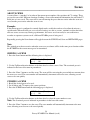
VIEW ANGLE & MIDI CHANNEL
The VIEW parameter adjusts the contrast of the display to allow for different lighting conditions or viewing
angles, to adjust the view angle:
1. Press the Utility button.
2. If not displayed, use the Up/Down buttons or Data Wheel to access the following page:
UTIL: View ChIn ChOut
0 01 01
3. Cursor right once to activate the “View” field and use the Up/Down direction buttons or data wheel to edit
the view angle.
Separate MIDI channels can be set for incoming MIDI messages and transmitted MIDI messages. The
“ChIn” parameter is used to set the receiving MIDI channel of the unit. The PC1600X will only respond to
incoming messages received on this channel. The “ChOut” parameter is used to set the transmitting channel
of the unit. Any messages set to transmit on the main channel use this parameter. Use the same procedures
listed above to access the MIDI parameters.
Note: For the PC1600X to receive the SysEx messages as listed in Appendix A. the ChIn value set on this
screen must match the channel byte in the message.
Many devices use SysEx command strings that include a MIDI channel or device number as one of the bytes.
This practice is beneficial to the user since it allows separate SysEx control when differentiating one unit
from an identical unit on the same MIDI stream.
Instead of hard coding these values into the strings a “gc” (global channel) or “dv” (device number) byte can
be designated that references the global setting. By altering this Utility setting all strings can be altered
simultaneously. When the PC1600X sees a “gc” in the string, it will transmit the ChOut setting. When it sees
a “dv” in the string, it will transmit the DevNum variable (see the “Device Number...” section in this
chapter).
18
Peavey PC1600X User Manual (rev-h)
MIDI FILTER
Selecting which MIDI messages will pass from MIDI IN to MIDI OUT is handled by the MIDI filter utility.
Individual messages or all MIDI messages can be filtered allowing only certain incoming messages to sass to
the MIDI OUT. The following messages can be filtered:
All MIDI (overrides all others when set to filter)
All Notes
Mod Wheel
Foot Pedal
Volume
Sustain
Reset Controllers
ALL Notes Off
Program Change
Polyphonic Aftertouch
Channel Aftertouch
Pitch Bend
System Exclusive
System Common
System Real-time
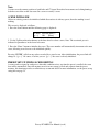
To set the status of a filter:
1. Press the Utility button.
2. Use the Up/Down buttons or data wheel to access the following page:
UTIL: Midi-Filter
Notes=Pass
3. Press the right direction button once to edit the filter tulle. Use the Up/Down buttons or data wheel to
display the different filter types. The field on the right displays whether the data is filtered or passed to the
MIDI OUT jack.
4. To toggle between “pass” and “filter.” simply press the right direction button while the filter type field is
active. The filter type field remains active until the left direction or Exit button is pressed.
PRESET MAPPING
In its default state, the PC1600x will echo Program Changes, but not respond to them. To make it respond,
you must go to the “MAP: Curr Midi map” screen and switch on one of the three map’s (instead of “Off”).
Then the PC1600X will respond to Program Changes on its MIDI IN channel (“ChIn” parameter on the first
utility screen) according to the mar). Mapping allows each of the 128 MIDI program change messages (0127) to recall any preset or send any scene. Follow the stems below to select which preset is recalled or
which scene is sent in response to a received program chance message:
1. Press the Utility button.
2. Use the Up/Down buttons or data wheel to access the following page:
MAP1: Prog 000->prs000
Preset Name Here
3. First cursor right to the digit after “MAP” Editing this value selects which MIDI map will be edited. This
19
Peavey PC1600X User Manual (rev-h)
should not be confused with the current MIDI map described below.
4. Cursor right again to the third field which displays a preset or scene number, this is the preset number
recalled or scene sent when the program change value in the second field is received. If a preset is selected,
the bottom line will display the preset name. When a scene is selected, the associated preset number will be
displayed.
Note:
Program Change Map1 and Map2 default to recall presets 0-49 with received Program changes 0-49.
Program Change Map3 defaults to send Scenes 0-99 with received Program changes 0-99.
PROGRAM CHANGE ENABLE AND CURRENT MAP STATUS
The current MIDI MAP parameter selects which map incoming program chances will use. Incoming
program chances can be ignored completely by setting the current map number to “Off”.
To set the current map number:
1. Press the Utility button.
2. Use the no/down buttons or data wheel to access the following Dace:
MAP1: Curr MIDI map
Off
3. Cursor right once to activate the field and use the Up/Down direction buttons or data wheel to edit the
marl number.
4. To ignore all incoming program changes, decrease the current map number until “off” is displayed.
DUMPING INTERNAL DATA
ALL internal data can be transmitted over MIDI to be saved on an external device. The MIDI Dump page
allows the following data to be transmitted:
ALL presets
All scenes
All global variables
The current preset
Everything
To transmit this information:
1. Press the Utility button.
2. Use the Up/Down buttons or data wheel to access the following page:
UTIL: dump [Enter]
Everything
3. Cursor right once to activate the field and use the Up/Down direction buttons or data wheel to edit the type
of data to be transmitted.
4. Press the “Enter” button to transmit the data.
Note:
Data dumps can also be requested remotely using the appropriate SysEx message (see Appendix A)
20
Peavey PC1600X User Manual (rev-h)
ASSIGNING FOOTSWITCHES
A footswitch can be assigned globally to duplicate most of the front panel buttons
1. on the PC1600x. Examples of footswitch uses include:
2. Changing presets on the PC1600x by assigning the footswitches to “lnc.” or “Dec.”
3. Saving and sending scenes by assigning a footswitch to copy the “Enter” button.
4. Starting and stopping a sequencer by assigning a button to toggle between Start
and Stop messages and assigning the footswitch to copy that button.
5. Sending note messages to drum machines allows drum Darts to be played with a
footswitch. Assign a button to send a note message and assign a footswitch to copy that button.
6. Muting an effect by duplicating a button message that mutes a fader.
To assign a footswitch:
1. Press the Utility button.
2. Use the Up/Down buttons or Data Wheel to access the following page:
UTIL: Ftsw1
Off
Ftsw2
Off
3. Select the correct footswitch field using the left and right direction buttons.
4. Use the Up/Down buttons or the data wheel to select which button the footswitch will emulate.
The polarity of the footswitch is automatically determined on power-up. If a footswitch is installed after the
PC1600X is powered up, or if the footswitch is depressed during power-up, the polarity of the footswitch
may be incorrect. Simply switch the power off, wait a few seconds and turn the power back on with the
footswitch installed but not pressed. This will correct the polarity.
Note: Assigning a footswitch will automatically disable the CV 2 input.
DEVICE NUMBER - NOTE RECORDING/RECEIVE CHANNEL
UTIL: DevNum RecChn
000
001
This screen allows the assignment of a global device ID. Many MIDI products use system exclusive
command strings that have a device number as one of the bites. These numbers are used to differentiate the
unit from an identical unit on the same MIDI stream. Being able to chance these numbers globally allows
you to use one set of PC1600X presets for multiple units of the same product. Instead of hard coding these
values into the strings, it is possible to designate a “dv” (device numbers byte in the strings. then adjust this
parameter to function as the Global setting.
21
Peavey PC1600X User Manual (rev-h)
The RecChn parameter is used when recording note messages into button strings. The Note Recording
Receive Channel parameter simple determines which channel notes will be accepted on. For more
information, check out the Note Stream Recording section on page 28.
MIDI TRANSMISSION DELAY
Sometimes a device can't handle MIDI data as fast as the PC1600x can generate it. This can happen when
sending scenes, dumping presets or during any other operation that sends large amounts of data. There are
two types of MIDI delay available to yon. They both default to zero and shouldn't be set otherwise unless a
problem is occurring with a receiving unit.
UTIL: DevNum RecChn
000
001
The first is a PER - SysEx message delay, which is inserted after the PC1600X sends an EOX byte (F7h).
This puts delays in between SysEx messages. The delay can be set from 0 to 100 ms, Try raising this number
in 5 ms steps if a unit chokes on SysEx data from sending scenes. (By “choking” we mean that the unit got a
MIDI receive error got hung, or dust didn't do everything that it should have.) Don't set this number higher
than needed. The maximum value of 100 ms will make a scene with 16 SysEx messages take almost 2
seconds to send.
The other type of delay is a Per-byte delay, which is inserted after every byte that the PC1600x sends. This
delay can be set from 0 to 1000 us (1 ms) in 10 us steps. If a computer or MIDI librarian is letting a buffer
overflow when you're backing up your PC1600x data. try setting this delay between 100 and 500 as needed.
(A value of 320 will essentially split the MIDI speed in half. You'll probably want to lower the delay when
you're done and only raise it when needed.
The Delay screen is displayed as follows:
MIDI: PerMsg PerByte
Delay 000ms 000ms
Note:
These delays only affect MIDI data that the PC1600X generates internally. Data that is received from MIDI
IN to MIDI OUT is not delayed.
REMOTE BUTTON SET-UP
The 16 programmable buttons are useful for sending any type of message to just about any MIDI device.
You can access the button messages remotely by sending simple messages into the PC1600X. All you need
is a MIDI keyboard, pedal board. or any other MIDI controller that sends Program Change commands or
MIDI Note On/ Note 0 messages (i.e. “MIDI-fied” foot pedals). For example use your note pedals to play
chords instead of single notes (With preprogrammed velocity or the velocity from the pedals). Reserve keys
on your keyboard for sending SysEx messages. Or use your Program Change pedal board to send more
complex MIDI messages (like SysEx or multiple Program Changes). The possibilities are virtually unlimited.
Move to the utility screen displayed below. Pick the emulation cache (Off, Notes, PrgCh) the MIDI channel
you are sending these messages on (1-16) and the starting value (0-127). The starting value is the base note
number or base program number depending on the emulation type. The base value will emulate button #1
while the next 15 values will emulate buttons #2-#15. The incoming message will not be echoed, even if the
button is “Off” (NOTE: Middle C on a MIDI keyboard is note number 60 (3Ch1.)
22
Peavey PC1600X User Manual (rev-h)
BUTN: Type CH Start
REMT Off 01 000
When the type is set to “Notes” Note On messages will emulate a button press, while Note Off messages
(including Note On with velocity = 0, of course) will emulate a button release. In “PrgCh” mode, . Program
Chance messages will emulate a button press immediately followed by the release, (You probably won't find
much use for a Prs/Rls string when emulating in PrgCh mode - use normal or toggled strings instead.)
INDIVIDUAL PRESET INITIALIZATION
When creating new presets, it is perfectly fine to edit existing presets. However if you prefer to start with a
“Clean Slate” a preset initialization function is available in the utility menu:
1. Press the Utility button
2. Use the Up/Down buttons to move to the following screen:
UTIL: Init a Preset
00
Volume with mute
3. Select the Preset number you wish to re-initialize.
4. Press “ENTER”, then you will be asked. “ARE YOU SURE”
5. Press “ENTER” again to confirm initialization. The preset will be renamed “--initialized--”
Note:
All presets share the same block of memory, which gets divided among the available presets. This utility is
very handy for freeing up memory since you can reinitialize presets that are not needed.
MEMORY USAGE
PC1600x presets are dynamically allocated, allowing a single preset to be very large when necessary. If too
many larvae presets are created, the PC1600x will run out of preset memory. When this occurs, some
memory must be freed by removing (reinitializing) or re-defining presets. The memory usage display help
determine which presets to modify. To use the memory usage display:
1. Press the Utility button.
2. Use the Up/Down buttons or data wheel to access the following page:
UTIL:
Memory
Free: 6324
4. Use the Up/Down buttons or the data wheel to view the amount of free memory and the amount of
memory used by each preset.
Note:
The names of faders, CV inputs and buttons only use memory per character. Therefore shortening the names
frees up memory. Preset names however have a fixed length so this wouldn't apply.
23
Peavey PC1600X User Manual (rev-h)
Scenes
-----------------------------------------------------------------------------ABOUT SCENES
A scene allows a “snapshot” to be taken of the current preset number, fader positions & CV settings. These
are saved in one of the 100 scene locations. Sending a scene will transmit the information for each fader/CV
Pedal just as it was saved. The scene will be sent referencing the preset that was active when the scene was
saved, not the preset active when the scene is sent.
Example:
If the current preset is configured to control digital tracks, each fader can be used to adjust the mix on a
specific track. When all faders are set to a desired setting, save this as a scene, continue to adjust the faders
and save scenes as necessary. During a performance, the scenes saved can easily be sent to the mixer,
recorder or sequencer system even if a different PC1600x preset is being used.
Repeatedly pressing the Scene button will toggle between the SCENE Send, Store and INITIALIZE pages.
Note:
The original preset that was active when the scene was saved must still be in the same preset location within
the PC1600X for the correct messages to be transmitted.
SENDING A SCENE
1. Press the Scene button until the following clave is displaced:
SCENE: Send [Enter]
[p:---]
00
2. Use the Up/Down direction buttons or the data wheel to select a scene. Note: The associated preset is
indicated in the lower left corner in parentheses.
3. Press the “Enter” button to send the scene. The scene will be sent using the preset which was current when
the scene was saved. The scene number will automatically increment to the next scene, allowing several
scenes to be sent quickly.
STORING A SCENE
1. Recall the desired preset to be used.
2. Set all faders and CV inputs to the correct positions.
3. Press the SCENE button until the following page is displaced:
SCENE: Store [Enter]
[p:---]
00
4. Use the Up/Down direction buttons or the data wheel to select the scene number to save.
Note: The associated preset is indicated in parentheses in the lower left corner.
5. Press the “Enter” button to save the scene. The scene number will automatically increment to the next
scene, allowing several scenes to be stored quickly.
24
Peavey PC1600X User Manual (rev-h)
Note:
A scene saves the current position of each fader and CV input. Data wheel movements and soloing/muting a
fader have no effect on the data stored in a scene or sent by a scene.
SCENE INITIALIZE
Allows an existing scene to be initialized which disassociates it with any preset, therefore making it send
nothing.
This screen is displayed as follows:
1. Press the Scene button until the following page is displaced:
SCENE: INITIALIZED!!!
[p:---]
00
[Enter]
2. Use the Up/Down direction buttons or the data wheel to select a scene, Note: The associated preset is
indicated in parentheses in the lower left corner.
3. Press the “Enter” button to initialize the scene. The scene number will automatically increment to the next
scene, allowing several scenes to be initialized quickly.
Pressing “ENTER” will clear any values recorded by a stored scene. After initialization, the preset link will
change to: “[p:---]” Of course, if at first you see “[p:---]” the scene is already initialized.
PRESET SET-UP STRING SCENE EDITING
A scene can be assigned to each preset, when this condition exists, any time the preset is recalled, the scene
data will be transmitted. Since the memory area for scene storage is fixed and separate from the preset
memory, this function provides an efficient way to transmit data. For more information, see the preset set-up
string info on page 32.
25
Peavey PC1600X User Manual (rev-h)
About Presets & Editing
-----------------------------------------------------------------------------Each preset contains a variety of information:
*16 fader messages
*16 button messages
*2 CV messages
*A group of “set-up” messages that are transmitted each time a preset is selected (recalled).
*Data Wheel Link
Fifty unique presets are available for editing, however we have pre-programmed each of them with a variety
of sample presets to give you application examples.
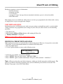
UNIT INITIALIZATION:
Initialization restores all 50 factor presets (and erases any settings you might have made), resets the global
settings and deletes any programmed scene settings. If you're sure you want to do this, use the following
procedure:
1. Turn Power Off.
2. Hold down the Utility and Enter buttons while turning the Power On.
3. “Memory initialized” is displayed.
Note: It is not possible to undo the initialization procedure.
INDIVIDUAL PRESET INITIALIZATION
When creating new presets, it is perfectly fine to edit existing presets. However, if you prefer to start with a
“Clean Slate” a preset initialization function is available in the utility menu.
1. Press the Utility button.
2. Use the Up/Down buttons to move to the following screen:
UTIL: Init a Preset?
00
Volume with mute
3. Select the preset number you wish to reinitialize.
4. Press “ENTER” then you will be asked. “ARE YOU SURE ?”
5. Press “ENTER” again to confirm initialization. The preset will be renamed “--initialized--”.
Note: ALL presets share the same block of memory, which gets divided among the available presets. This
utility is very handy for freeing up memory since you can reinitialize presets that are not needed. The
Memory Usage page is also in the Utility Menu.
26
Peavey PC1600X User Manual (rev-h)
EDIT INTRODUCTION
Access the main edit maple at any time by pressing the Edit button. The field on this page selects the item to
be edited. The following choices are available:
•
•
•
•
•
•
Fader 01 - Fader 16
CV 1 & CV 2
Button 01 - Button 16
Data wheel
Set-up string
Name/save preset
The up and down direction buttons or the data wheel can be used to scroll through the above choices.
Moving any Fader, CV input or Button will cause that item to be displayed, when the desired item is
displayed, press the “Enter” button to access the parameters specific to that item.
Shortcut: For a time-saving shortcut, try moving a fader, CV input button or the Data Wheel while holding
the edit button. Releasing the edit button will immediately access the selected item. “Sideways/Navigation”
is possible when switching to a device that is set to the same function. This will allow you to jump to a
different device and be at the same screen as the previous device.
NAMING & SAVING A PRESET
Go to the Edit menu. Use the Data Wheel or Up/Down arrow keys to move to the “Name/save Prs” page,
Press “ENTER”, Use the Left/Right direction buttons to select the character in the name and the Up/Down
buttons or data wheel to edit the character. To make editing faster, each fader edits a different character of
the name. Pressing “ENTER” from this page accesses the “SAVE TO” page. The bottom line of this page
displays the number and name of the destination preset to be overwritten, The data wheel and Up/Down
buttons maybe used to change the storage destination. Pressing the “Enter” button from this page will save
the preset and return to the main page, by pressing the Exit button, you will be returned to the “Edit name”
page.
EXITING EDIT MODE
To return to the main page at any time, Press Exit several times until the main page is reached. If changes
were made to the preset, the preset number will be replaced with “**” This is an indication that the preset in
the edit buffer has been modified but not saved. Press Edit to return to the Edit mode if the chances are to be
saved.
Changing presets results in the following display:
[Enter]
Exit without saving?
Press “ENTER” to confirm that you don't want to save your edits. Press Up/Down from the main page to
leave this preset. This will cause any chances that were made to be discarded. However, if you don't edit
another preset, recovery is possible. Edits which were discarded can be recovered from the main page.
Increment the preset number above preset 49 and the preset number is replaced by “**” Pressing Edit returns
to the Edit mode with the edit buffer exactly as it was last time the Edit mode was exited (even if the unit had
been Dowered down. Amazing!)
27
Peavey PC1600X User Manual (rev-h)
ACCESSING GLOBAL SETTINGS WITH SPECIAL MIDI MESSAGES
Many MIDI products use system exclusive command strings that have a MIDI channel or device number as
one of the bytes. These numbers are used to differentiate the unit from an identical unit on the same MIDI
stream. Being able to change these numbers allows you to use one set of PC1600X presets for multitude
units of the same product.
Instead of hard coding these values into the strings, you can designate a “gc” (global channel) byte or a “dv”
(device number) byte in the strings. then just go to UTILITY and change the ChOut (1st screen) and
DevNum (7th screen) parameters.
Whenever the PC1600x sees a “gc’ in a string, it will transmit the ChOut parameter minus 1 (0-15h). When it
sees a ‘dv” it will transmit the DevNum parameter (0-127 / 00h-7Fh)
Additionally, the “gc” designation can be placed after a channel status byte (80h through EFh). In this case,
the “gc” will channelize the status bite, as opposed to it being sent as a separate byte. The status and “gc”
bytes will be connected by a hyphen to show that they are being combined into a single byte upon
transmission. The following screen would program fader //1 to send Program Changes on the global out
channel. The zero after the C will get replaced by ChOut -1 (0 - F), therefore making it meaningless (A CF
would make no difference to the fader function).
FDR01: String
C0-gc pr
To program one of these values in a string (fader, CV, button or set-up, edit the byte value up to FD or FE, at
which point you will see “dv” or “ac” on the display, respectively (instead of “FD” or “FE”)
NOTE: In button and setting strings, the first byte of the string cannot be a “dv” or “gc” This allows the user
to send the raw values add (undefined) and few (active sensing) over MIDI. if desired. by programming them
as the first byte.
28
Peavey PC1600X User Manual (rev-h)
Editing The Faders
-----------------------------------------------------------------------------DEFINING AND NAMING
When a fader is selected to be edited, the first page displayed selects the function of the fader. A fader can be
assigned to the following functions:
No Message
Continuous Controller
Master Fader
MIDI string
To set the function of a fader:
1. Access the following fader function display by pressing Edit from the main page, then moving fader 01
Next, press “ENTER”.
FDR01: Function
No Message
2. Cursor right to select the function for the fader (it will blink). Press the Up/Down buttons to access any of
the four choices: No message, Controller, Master fader or String.
3. Press EXIT to deselect the item. Except when “No messages is selected, access to additional parameters
and naming for this fader is available by pressing the up direction button (when the function field is not
blinking).
After assigning a function to the fader, the fader can be named. To name the fader:
1. With no parameters flashing, press the up direction button until the following page is displayed.
FDR01: Name
<Name>
2. Use the left/right direction buttons to select the character in the fader name. Next, press the Up/Down
direction buttons, data wheel, and/or the current fader to change (edit) the character.
NO MESSAGE
A fader can have its function set to “No message's with this option, moving the fader will (of course) have no
action.
CONTINUOUS CONTROLLER
A fader can be programmed to send a continuous controller message whenever the fader moves. The MIDI
channel can be set to any specific channel, or to the main transmit channel set in the Utility section. The
controller number can be set to any value from O to 120.
29
Peavey PC1600X User Manual (rev-h)
The ”Min” parameter determines the value sent when the fader is in its lower-most position next to the
button.
The ”Max” parameter determines the value sent when the fader is in its upper-most position. Simply
exchange the values in these two parameters to reverse the polarity of a fader.
The “Mode” parameter determines how matching incoming controller messages will be handled. The three
modes are as follows:
Merge:
Incoming controller messages that match a fader are always passed through the PC1600x. The MIDI data
generated from fader movement is merged with the data passing through the unit.
Replace:
Incoming controller messages that match a fader are passed through the PC1600x until the fader is moved.
The matching incoming controller messages are filtered until the Exit button is Pressed while on the Main
Page. This mode allows direct replacement of data in an existing stream of controller messages.
Update:
Incoming controller messages that match a fader are passed through the PC1600x until the fader is moved.
The data sent when the fader first moves will always match the last value that passed through the PC1600x,
regardless of the position of the fader. The matching incoming controller messages are filtered until the Exit
button is pressed while on the main page. This mode allows seamless modification of data in an existing
stream of controller messages.
To define a fader as a continuous controller:
1. First, set the function to “Controller” press the left/right, or Exit button to deselect the edit field, then press
the up button to move to the following page:
FDR01: Chnl
16
Num
007
2. Cursor over to the “Chnl” field and set the MIDI channel for the controller message. Incrementing the
channel number above 16 will display “ChOut.” When “ChOut” is selected, the controller message will be
transmitted on the global MIDI transmit channel from the Utility menu.
3. Cursor over to the “Num' field to set the controller number to be transmitted. See Appendix C for a list of
MIDI Controller numbers.
4. With no parameters flashing, press the up direction button to access the following page:
FDR01: Min
000
Max
127
5. Cursor left or right to the Min or Max field and edit the value as necessary (range=O-127).
6. With no parameter flashing, press the up direction button to access the mode page:
30
Peavey PC1600X User Manual (rev-h)
FDR01:
Mode
Merge
7. Cursor rig or left to access the “Mode” parameter, select either Merge, Replace or Update.
Master Fader/CV
Several faders can be aroused together and controlled by another fader. This is done by defining a single
fader or CV pedal as the master fader as shown:
1. Set the function to “Mater Fader” next press the up direction button when the function field is not
blinking, the following page will be displayed:
FDR01: Master of
Fader01= No
2. Cursor right once to activate the “Master of” field. Set this field using the Up/Down direction buttons, the
data wheel or the current fader. Moving any fader will select the fader moved.
3. The “Yes” or “No” on the right shows whether the fader in the “Master or' field is being controlled by the
current master fader. To toggle between “Yes” and “No.” simply press the right direction button. The
“Master of' field will remain active.
MIDI STRINGS
Any MIDI message can be assigned to a fader by “Entering the message as a hexadecimal string. A legible
“parameter format” allows the current fader position to be inserted into the message in one of many different
formats. A programmable minimum and maximum parameter value allows the parameter to span practically
any range. To define a MIDI message string: 1. Select the function “String”. Next, press the up direction
button when the function field is not blinking. The following page will be displayed:
FDR01: String
F0 00 F7
2. To edit the string, use the four direction buttons, the data wheel and the current fader. The left/right
direction buttons are used to select a specific byte, while the Up/Down direction buttons, the data wheel and
the current fader are used to edit a digit of the string. Pressing the “Up” button when “Between Bytes”
inserts a byte and pressing the “Down” button deletes the byte to the right of the cursor.
3. Replace with “pr” any byte that will be determined by the fader position. This is done by incrementing the
byte until “pr” is displaced. When the string is finished, press Exit.
4. Access the minimum and maximum parameters by pressing the up direction button when the underscore
cursor is not displayed.
FDR01: Min
0
Max
127
5. Cursor over to either parameter and edit the value. Use the fader to set the parameter to the approximate value necessary. Use
the data wheel or the Up/Down buttons to “Enter” the exact value.
6. When neither field is flashing, press the up direction button to access the parameter format page:
31
Peavey PC1600X User Manual (rev-h)
FDR01: Param format
Single Byte
7. The value selected here determines how the “pr” bytes will be filled with the parameter value. Refer to your unit's owner's
manual to determine which format to use. For a detailed description of the parameter formats, see Appendix-B.
DEALING WITH CHECKSUM VALUES
Some products call for checksum bytes in their SysEx implementation in order to specify a byte as
checksum, A “cs”' can be added to the string. To program, just edit the byte up to what would normally be
“FC”, displayed in its place will be “cs” Here is an example string with an extended display to show you the
entire string:
FDR01: String
F0 41 10 70 12 00 00 01 PR CS F7
The PC1600x will compute the checksum as follows:
Adds up all bytes from byte #5 or higher, see below, when FO is byte #0b to the last byte before the “cs.”
Note: byte #5 is typically the start of the data portion of the SysEx.
Takes the 2's complement (flips all the bits, then adds 1).
Uses the least significant 7 bits of the result as the checksum byte, The 8th byte is always zero.
With some SysEx messages, the unit ID (byte #3 and command ID byte #4) could be extended beyond a
single byte by using leading zeroes before the non-zero bite, In this case, the PC1600x's checksum
calculation will start later in the string accordingly: at byte #(5 + number of leading zeroes). Note: The “cs”
computation is unavailable in button and set-up strings. In these cases, the checksum must be calculated and
inserted into the string as a constant by the programmer. Be sure and refer to your product owner's manual
for the necessary values/massages.
ASSIGNING STRING DEVICE IDS AND MIDI CHANNELS TO GLOBAL
SETTINGS
Many devices use SysEx command strings that include a MIDI channel or device number as one of the bytes.
This practice is beneficial to the user since it allows separate SysEx control when differentiating one unit
from an identical unit on the same MIDI stream.
Instead of hard coding these values into the strings, a “gc” (global channel) or “dv” (device number) byte
can be designated that references the Global settings in the Utility section. When the PC1600x sees a “gc” in
the string, it will transmit the Utility menu's ChOut setting. When it sees a '”dv” in the string, it will transmit
the DevNum variable:
FDR01: String
F0 00 00 1B gc F7
Additionally, the “gc” designation can be used with MIDI Channel messages. In this case, the “gc” will
channelize the preceding byte, as opposed to being sent as a separate byte. For display, the status and “gc”
bytes are connected by a hyphen to show that they are being combined into a single byte. The following
example is how this would be displayed:
32
Peavey PC1600X User Manual (rev-h)
FDR01: String
C0-gc pr
The zero after the C will get replaced by the ChOut setting in the Utility menu.
LEARN MODE
If a system exclusive message is received while a fader string is being edited (the underline cursor must be
presents. the PC1600x will automatically replace the existing fader string with the system exclusive message
received.
SAVING YOUR EDITS
Use the following steps to save your edits:
1. Press the Edit button.
2. Use the data wheel or no/down buttons to scroll to the last option: Name/save preset.
3. Press “Enter”.
4. To rename, use the left/right buttons to select character positions and the Up/Down buttons to edit the
character. Note: Faders also can be used to select character positions.
5. Press “Enter”.
6. Choose the destination for the save with the Up/Down buttons or the data wheel.
7. Press “Enter” to save to the location displaced at the bottom of the display.
To return to the main page at any time, press Exit several times until the main page is reached. If changes
were made to the preset, the preset number will be replaced with “**” This is an indication that the preset in
the edit buffer has been modified but not saved. Press Edit to return to the Edit mode if the changes are to be
saved.
Press up or down from the main page to leave this preset. This will cause any changes that were made to be
discarded.
Note: Edits which were discarded can be recovered from the main page if no other preset has been edited
seven after a Dower down). Increment the preset number above preset 49 and the preset number is replaced
by “**” Pressing Edit returns to the Edit mode with the edit buffer exactly as it was last time the Edit mode
was exited.
33
Peavey PC1600X User Manual (rev-h)
Editing The Buttons
-----------------------------------------------------------------------------DEFINING AND NAMING
When a button is selected to be edited, the first page displayed selects the function of the button. A button
can be assigned to the following functions:
Off/Fader ID
Mute fader
Solo fader
Program chance message
Note on/off message
MIDI string MIDI string with button Dress. MIDI string with button release
Toggle between two MIDI strings
Send Fader
Send Scene
To set the function of a button:
1. Press EDIT, then press a button to select it (in this example. button 16. Press “Enter” to access the
following dated
BTN16: Function
Off / Fader ID
2. Press the right direction button to select the function (it will blinks. then use the Up/Down buttons or data
wheel to select the desired function.
3. Use the up direction button when the function field is not blinking to access other parameters. Press either
of the left/right direction arrows (or exit) to de-select (stop the blinking).
After assigning a function to the button, the button can be named.
To Name the button:
1. With no parameter selected and a function other than “Off / Fader ID” selected, press the up direction
button until the following page is displayed:
BTN16:
Name
<Name>
2. Use the left/right direction buttons to select the character in the button name and the Up/Down direction
buttons, Data Wheel and/or the fader above the button to edit the character.
OFF/FADER ID (NO MESSAGE)
Whenever one of the 16 programmable buttons is programmed as “Off/Fader ID” it will identify its
associated fader when on the top of the preset screen, For example, pressing button 16 would cause the
PC1600x to display “Fdr16 : <fader name>. This allows you to see what the fader is going to do (if it is
named) before moving it, without having to look at the edit screens.
34
Peavey PC1600X User Manual (rev-h)
MUTE/SOLO FADER
A button can be assigned to mute the associated fader. Pressing the button will mute the fader by sending the
minimum value for the fader, and then disable the fader. When muted, moving the fader will have no effect.
When the button is pressed again, the current fader message is sent, and the fader is enabled. To program a
button to mute the associated fader, simple select “Mute fader” for the button function.
A button can be programmed to Solo the associated fader my simply selecting “Solo Fader” function for the
button. With this function, pressing the button will send the minimum value for each fader except the
button’s associated fader. To restore any fader, simply move the desired fader. To cancel the Solo entirely,
simply press ““Enter”’ button with the “main” page displayed.
PROGRAM CHANGE
A button can be assigned to send a program chance message each time it is pressed. The MIDI channel can
be set to any MIDI channel, or to the main transmit channel set in the Utility section. The program number
can be any value from 000 to 127.
To set these two parameters:
1. From the button function page, select “Program Chng”. Next, deselect then press the up direction button.
The following page will be displayed:
BTN16: Chn1
01
Program
000
2. Cursor over to the “Chin” field and set the MIDI channel for the program change message. Incrementing
the channel number above 16 will display “ChOut.” When “ChOut” is selected, the program change message
will be transmitted on the Global MIDI channel set in the Utility menu.
3. Cursor over to the “Program” field to set the program number.
NOTE ON/OFF
A button can be assigned to send a note-on message when the button is pressed, and a note-off message
when the button is released. The MIDI channel can be set to any specific channel, or to the main transmit
channel set in the Utility section. The note number can be set to any note from C-1 to G9. The velocity can
be set to any specific value (1-127), determined by the current fader position fair), or determined by
incoming MIDI velocity (Rem) when button remote is used.
To set the parameters:
1. From the button function page, select “Note-on/off.” Next, deselect then press the up direction button. The
following page will be displaced:
BTN16: Chn1 Note
01
C4
Vel
127
2. Cursor over to the “ChIn” field and set the MIDI channel. Incrementing the channel number above 16 will
display “ChOut”, which references the global MIDI channel.
3. Cursor over to the “Note” field to set the note number.
4. Cursor over to the “Vel” field to set the velocity value. Incrementing the velocity value above 127 will
35
Peavey PC1600X User Manual (rev-h)
display “Fdr”. This option allows the current position of the fader to set the note-on velocity. Pressing the up
button again will display “Rem”. This substitutes the incoming MIDI velocity when the button is activated
via a MIDI “note on” message. When pressed locally, “Rem” will act like the “Fdr” setting and velocity will
be determined by fader position.
MIDI STRINGS
A button can be assigned to transmit just about any MIDI message when pressed. These messages are
“Entered in hexadecimal form or captured via MIDI (see “Learn Mode” on page 24.
To define a button MIDI string:
1. From the button function page, select “String”. Next deselect and press the up direction button. The
following page will be displayed:
BTN16:
F0 00 F7
String
2. Use the left and right direction buttons to select a byte to be edited. When the cursor is on a digit, the up/
down direction buttons, data wheel and/or associated fader will edit the digit. Pressing the up button when
between bytes insets a byte and pressing the down button between bytes deletes a byte.
STRING PRS/RLS
A button can be assigned to transmit any MIDI messages when Dressed and any other MIDI message when
released. These messages are “Entered in hexadecimal form.
To program the Press and Release String:
1, From the button function page, select “String Prs/Rls.” Next, deselect, then press the up direction button.
The following clave will be displayed:
BTN16: Press String
F0 00 F7
2. “Enter” the MIDI string.
3. After editing the “Press string's” press Exit. Press the up direction button to move to the release string
displayed as follows:
BTN16: Rls String
F0 00 F7
4. “Enter” the “Rls’ String.
STRING TOGGLE
A button can be assigned to toggle between any two MIDI message strings. These messages are “Entered in
hexadecimal form.
To program the two strings:
1. From the button function pace, select “String toggle”. Next, deselect then press the up direction button.
The following page will be displayed:
BTN16: String 1
F0 00 F7
36
Peavey PC1600X User Manual (rev-h)
2. “Enter” the first string.
3. Exit from editing the first string then Dress the up direction button to edit the second string displayed as
follows:
BTN16: String 2
F0 00 F7
4. Edit the second string as necessary.
ASSIGNING STRING DEVICE IDS AND MIDI CHANNELS TO GLOBAL
SETTINGS
Many devices use SysEx command strings that include a MIDI channel or device number as one of the bytes.
This practice is beneficial to the user since it allows separate SysEx control when differentiating one unit
from an identical unit on the same MIDI stream.
Instead of hard coding these values into the stings, a “gc” (global channel) or “dv” (device number) byte can
be designated that references the Global settings in the Utility section. When the PC1600x sees a “gc” in the
string, it will transmit the Utility menu's “ChOut” setting. When it sees a “dv’ in the string it will transmit the
“DevNum” variable.
FDR01: String
F0 00 00 1B gcF7
Additionally, the “gc” designation can be used with MIDI Channel messages. In this case, the “gc” will
channelize the preceding byte, as opposed to being sent as a separate byte. For display, the status and “gc”
bytes are connected by a hyphen to show that they are being combined into a single byte.
The following example is how this would be displaced:
FDR01: String
C0-gc pr
The zero after the C will get replaced by the “ChOut” setting in the Utility menu.
RESPONDING TO REMOTE VELOCITY MESSAGES
When using “Note” mode (the Button Remote page in the Utility menu is set to Type=Notes). To play MIDI
notes or chords the PC1600x (per note) can be programmed use a fixed velocity, or to use the velocity that
comes in via MIDI (e.g. from velocity sensitive note pedals or keyboards. If the button is programmed as a
single note, set the velocity variable to “rv” for Remote.
This is one example:
BTN16: String
90 60 rv
If playing a chord (a button is programmed to transmit several notes via a MIDI string). edit the string and
set the velocity bites up to FF. which accesses “rv” (remote velocity) in the string instead of the FF.
Whenever the PC1600x sees an 'rv' in a button string and the most recent status byte in the string was a Note
On (9x for attack velocity) or Note 0ff (8x for release velocity). it will substitute the incoming velocity.
37
Peavey PC1600X User Manual (rev-h)
If the button is programmed to transmit a single note on message using the button “Note On” function (vs. a
MIDI string) the screen would be displayed similar to this:
BTN16: Chnl
01
Note
C4
Vel
Rem
As mentioned earlier the “Rem” designation indicates that velocity will be determined from remote MIDI
input, if a button is pressed locally (on the PC1600x itself) or a Program Change is received, the “rv” byte
value (or “Rem” setting) will be determined by the position of the fader above the button, even if it did not
follow a “9x” or an “8x”. The fader position number will always be ranged from 0-127 (or 1-127 if within a
note streams. It will not be affected by the fader's Min and Max parameters.
NOTE:
Since the “rv” velocity will use the fader position when the button is pressed on the PC1600x it is useful to
use “rv” even when not using the remote feature. It gives you a method of inserting the fader position (0-127
only) into any button string. Use it for program number, note number etc. If the fader is not being used for
something else, however it is probably better to program the message into the fader, then set the button to
“Send Fader”.
LEARN MODE
If a system exclusive message is received while a button string is being edited (the cursor must be visible).
the PC1600x wilt automatically replace the existing button string with the system exclusive message
received. Note recording is also possible with this function. See below for more information.
NOTE STREAM RECORDING
To make chord programming easier, the PC1600x can now record note streams into button strings. This
allows you to play a chord into the PC1600x to program a button instead of inserting all of the numbers in
manually. To set up note recording, you must first enable the feature by telling the PC1600x which MIDI
channel you will be sending the note data over. This parameter/screen is located in the Utility menu (alone
with the MIDI Device Numbers):
MIDI; DevNum
000
RecChn
000
After setting the channel, go to any button's string editing screen (String, Prs/Rls or toggle) and hit the left or
right arrow button to put the underline cursor on the screen:
BTN01:
90 3C 7F
String
The recording will be triggered by any Note On received on the specified channel. Any Note Off received on
that channel will erase the string, allowing you to experiment until you find the right group of notes. Any
other MIDI commands will not affect the recording. When finished, press the “ENTER” button while
continuing to hold the chord. (if you're using 2-handed chords you can plug a footswitch into the PC16000x
and set it to emulate the “ENTER” button - see the 6th screen under UTILITY.)
38
Peavey PC1600X User Manual (rev-h)
NOTE:
Any Note 0ff will erase the whole chord, even though the other notes may still be sounding. If you play 3
notes, release 1 of them, then add another (still 3 soundings, then press “ENTER”, the last note will be the
only one recorded.
Therefore whenever you are going to release any notes (because the chord is not yet complete) release all the
notes and retrigger the whole chord.
You will not see the note stream on the screen until after you press the “ENTER” button. The string will start
with a “9x” (where the x is the note record channel – 1) followed by the first note number, then the first note
velocity, etc.
(Only one status byte - we're using running status here.) The velocity bytes can be changed to ‘rv” so that the
incoming MIDI velocity (or fader position) gets substituted allowing “Dynamic” remote button playing.
The following screen shows a “dynamic” C major triad on Channel 1 (starting with Middle C):
BTN01:
String
90 3C rv 40 rv 43 rv
So now that we know how to trigger chords remotely, how do we turn them off? There are two ways to do it.
The easy and memory-efficient method is to use the MIDI ALL Notes of command. This is a channelized
command that tells a Synth/MIDI device to release all of the notes that were triggered on that channel. The
command is defined as continuous controller #123 (7Bh) with a data value of zero:
All Notes 0ff command for:
channel 1: B0 7B
00
channel 2: B1 7B
00
You can use Prs/Rls strings with the chord on the press and the All Notes 0ff message (same channel of
course) on the release. This will act like a normal “Gated” triggering system (like a keyboard). You could
also insert the All Notes Off command in regular “Press Only” strings ahead of the chord so pressing any
button will release the previous chord before slaving its own chord before playing its own cord also letting
you release the button without releasing the chords. Just remember to program one of the buttons as an “All
Notes Off” only, so you can silence the sound source when needed.
You may find that the ALL Notes Off command doesn't work correctly in your system. There are some
Synths/MIDI devices out there that do not respond to the All Notes Off message and even some that respond
to it incorrectly.
Some units will “Kill” the notes abruptly instead of releasing them (as a Note Off would) and some others
will apply the message to all notes in the unit not just the ones that were generated on the same MIDI
channel as the ALL Notes Off message itself. If your Synth/devices respond correctly great! If not. You'll
have to send matching Note Off commands after the Note On commands.
The PC1600x won't record Note Off streams but there is a fairly easy way to handle this for the “Gated”
mode.
After recording the chord into the press string, record the same chord into the release string and then either
change the “9X” at the start of the string to an “8x” (Which will give you control over release velocity) or
change all the velocity bytes to zero which will convert the Note On’s to Off’s.
39
Peavey PC1600X User Manual (rev-h)
SEND FADER
This feature allows you to send single messages (as opposed to “sweeps” of messages) from the faders. This
is desirable in many cases like when sending very precise control chances into a sequencer.
When a fader's button is programmed as “Send Fader” moving the fader will not cause a MIDI transmission.
You will however see the data value on the top preset screen as you would normally except that there will be
an “M” in the lower right corner of the LCD telling you that the fader is temporarily muted. After you move
the fader to the desired position press the button to send the message (you will see the “M” disappear
signaling that the message was sent).
You can also use the Data Wheel to change the value before it is actually sent, if I is linked to the fader
(either directly or with “Last Fader”). Pressing a “Send Fader” button will switch to the “Last Fader Moved”
(even if the fader itself was not moved).
You can also set a normal “Sweep” from the fader by holding the button while moving the fader (or data
wheel). In this case the “M” will not be on the LCD signaling that the message is being transmitted.
BTN01:
Function
Send Fader
NOTE: When using faders to send continuous controller messages the replace and update modes will be
unaffected by fader movements when the button is not pressed, In other words the incoming controller won't
get filtered until the local controller is REALLY transmitted.
SEND SCENE
You can send any scene from one of the 16 buttons. This is useful when you know that you're
going to transmit particular scenes from a preset. It saves you from having to go to the
SCENE page, choose the scene and then send it with the “ENTER” button.
Choose “Send Scene” as the button function and the next screen will allow you to nick the
desired scene.
BTN01:
Function
Send Scene
BTN01:
[p:32]
Scene
02
SAVING YOUR EDITS
Use the following steps to save your edits:
1. Press the Edit button.
2. Use the data wheel, Up/Down buttons or press button 16 to scroll to the last option: Name/save preset.
3. Press “Enter”.
4. To re-name use the left/right buttons to select character positions and the Up/Down buttons to edit the
character. Note: Faders also can be used to select character positions.
5. Press “Enter”.
6. Choose the destination preset (will be overwritten).
40
Peavey PC1600X User Manual (rev-h)
7. Press “Enter” again to save to the location displaced at the bottom of the display.
To return to the main page at any time press Exit several times until the main page is reached. If chances
were made to the preset, the preset number will be replaced with “**” this is an indication that the preset in
the edit buffer has been modified but not saved. Press Edit to return to the Edit mode if the changes are to be
saved.
Press up or down from the main page to leave this preset. This will cause any changes that were made to be
discarded.
Note: Edits which were discarded can be recovered from the main page if no other preset has been edited even after power-down. Increment the preset number above preset 49 and the preset number is replaced by
“**” Pressing Edit returns to the Edit mode with the edit buffer exactly as it was the last time the Edit mode
was exited.
41
Peavey PC1600X User Manual (rev-h)
CV Pedals, Footswitch & Data Wheel
-----------------------------------------------------------------------------EDITING CV 1 & CV 2
The CV 1 and CV 2 inputs will accept a Control Voltage foot pedal. Press EDIT. then select CV 1 or CV 2.
Press “ENTER” to move to the function edits page:
CV 1: function
No Message
Control voltage inputs are programmed like the faders. Refer to the “Editing the Faders” chapter describing
how to define a fader.
Note: The dual footswitch parameters must be disabled (turned off) for CV 2 to work correctly.
WHAT TYPE OF CONTROL VOLTAGE PEDAL IS REQUIRED
Any 0-10 volt control voltage pedal or 1OK potentiometer pedal (unpowered) should work. As of this
writing, both Roland (EV-5, EV-1O) and Ensoniq (CVPI) offer control voltage pedals that will work with
the PC1600x.
DUAL FOOTSWITCH EDITING
The dual footswitch is set up globally in the Utilities menu, each pedal can be programmed to control:
Up/Down
“Enter”
Button functions
EDITING THE DATA WHEEL
The data wheel is programmed by linking it to a fader or CV input. When the data wheel is linked to a Fader,
CV input, it will adjust that parameter using the current Fader, CV position as a starting point. The data
wheel can also be set to link to the last Fader/CV moved instead of a specific fader.
1. Press EDIT, then select “Data Wheel, Press “Enter” to move to the following page:
Wheel; Link
None
2. Use the Up/Down buttons or the data wheel to select a fader or CV input. Also, moving a fader or CV
input will cause them to be selected.
3. Increment until “Last moved is displayed to make the data wheel always edit the last fader or CV input
that was moved.
42
Peavey PC1600X User Manual (rev-h)
Defining The Preset Set-Up String
-----------------------------------------------------------------------------When a preset is selected/recalled, each MIDI channel can send out an associated bank select message,
Program change message and volume message. The preset string can also be linked to a scene in addition to
an 80- byte programmable string.
BANK/PROGRAM/VOLUME
To program these options:
1. Press Edit, then select “Setup string”. Next, press “Enter” to access one of the three set-up pages. The
bank select, program chance and volume for each channel are available on the first page:
Setup;
Ch01
Bank
Off
Prog
Off
Vol
Off
2. Cursor right to the “Ch” field. Changing this field causes the bank, program and volume fields to display
the information for the selected channel.
3. Cursor right to the “Bank” field. This field displays the bank number to be sent for this channel.
Decrementing this field below zero (off) causes no bank message to be sent. When the Bank parameter is set
to 0-127, the full Bank Select message is transmitted with a zeroed MSB and the Bank number in the LSB.
Some products use the MSB directly to chance bands ignoring the LSB. Because of this the PC1600Xs Bank
parameter can be incremented further past 127. This new range is shown as 001m - 127m. When one of these
values is used the Bank will be sent as the MSB and the LSB won't be sent. For example, bank 002n on
Channel 1 would be transmitted as follows:
Hex
Description
B0
Status
00
CC#
02
MSB
NOTE: There is no “000m” choice in the list.
To switch an “MSB” unit to bank #0, use the 000 (LSB) selection since that will send a zeroed MSB along
with the zeroed LSB.
More About Bank Select
MIDI specifies the Bank Select message as a full l4-bit controller message, (Two 7-bit controllers combined
into a 14-bit number). The MSB (Most Significant Byte) is controller #0, while the LSB (Least Significant
Byte) is controller #32 (#20h). The bank number is computed as (MSB * 128) + LSB, hence, to switch to
bank #2 on Channel 5, the MIDI message would look like this:
Hex
Description
B4
Status
00
CC#0
00
MSB
20
CC#32
02
LSB
4. Cursor right to the “Prog” field. This field displays the program number to be sent for this channel.
Decrementing this field below zero (off) causes no program message to be sent.
5. Cursor right to the “Vol” field. This field displays the volume to be sent for this channel. Decrementing
this field below zero(0) causes no volume message to be sent.
43
Peavey PC1600X User Manual (rev-h)
6. Repeat the above steps as necessary for each channel.
7. With parameters deselected (press exit) press the up direction button to access the screen recall screen.
SCENE RECALL
Setup:
[P;--]
Scene
Off
A scene can be part of the set-up string. When this condition exists, any time the preset is recalled the scene
data will be transmitted. Since the memory area for scene storage is fixed and separate from the preset
memory, this function provides an efficient way to transmit data. Previously this information would have
been stored in the set-up MIDI string which would have been both tie and memory intensive. Note that when
a scene is selected for the result scene, its associated preset is indicated in the lower left corner.
MIDI STRING
1. With parameters deselected (press EXIT). Press the up direction button to access the string on the
following page:
Setup:
String
2. Edit the MIDI string just like a button string. The left/right direction buttons are used to select a specific
byte while the Up/Down direction buttons and the data wheel are used to edit a digit of the string. Pressing
the up button when between bytes inserts a new byte and pressing the down button deletes a byte. If no bytes
are displaced, no string will be sent.
LEARN MODE
If a system exclusive message is received while a set-up string is being edited (the cursor must be visible) the
PC1600X will automatically replace the existing set-up string with the system exclusive message received.
44
Peavey PC1600X User Manual (rev-h)
Copy Functions
-----------------------------------------------------------------------------The Copy functions can be accessed by pressing the COPY button. When pressing COPY from the main
screen, the Copy area is used to copy presets and scenes only. When accessing it from the EDIT menu, a
wide variety of source types can be copied. This includes a fader, CV input, button, data wheel, set-up string
or preset name.
COPYING FROM THE MAIN MENU
The Copy function is used to copy from one preset to another or from one scene to another. To perform a
copy:
1. Press the Copy button from the main page to access the following page:
Copy: Prs00->00 [Enter]
<Preset Name>
2. Cursor left or right until the first field is active.
3. Use the Up/Down direction buttons or the data wheel to select the source preset or scene. When this field
is active the bottom line displays a preset name if a preset is selected.
4. Cursor right to select the destination preset or scene. If a preset is selected the preset name will appear on
the bottom line when this field is active.
5. Press the “Enter” button to perform the copy.
COPYING FROM THE EDIT MENU
When in the Edit mode, any copy of the edit buffer can be defined by copying FROM any existing preset or
the current edit buffer, In other words you start from a destination preset and copy items to its edit buffer.
To perform a copy:
1. Select the destination preset. Move to any area in the Edit mode.
2. Press the Copy button to access the following type of page:
Copy:
[Enter]
3. Cursor left or right until the first field is active. Use the Up/Down direction buttons or the data wheel to set
the source cache. This can be a fader, CV input, button, data wheel, set-up string or preset name. Moving any
fader or button selects that device.
4. Cursor right to the second field. This selects the destination for the copy. Any preset or the current edit
buffer can be used as a source preset.
5. Cursor right to the third field. This field selects the destination within the current edit buffer.
6. Press the “Enter” button to perform the copy.
Remember - Copied messages must be saved to become a permanent part of the preset. For more information
review the “Saving Your Edits” section of the “Editing” the Buttons” chapter.
45
Peavey PC1600X User Manual (rev-h)
Appendix A
-----------------------------------------------------------------------------PC1600x System Exclusive Messages
Recall Preset: F0 00 00 IB OB ch 00 pp F7
When this is received the PC1600x will switch to the preset specified by “pp” regardless of the current MIDI
mapping.
Send/Recv All presets: FO 00 00 IB OB ch 01 {data} F7
This message is sent and received by the PC1600x. It contains all preset data including the current edit
buffer.
Send/Recv All scenes: F0 00 00 IB OB ch 02 {data} F7
This message is sent and received by the PC1600x. It contains all scene data.
Send/Recv All globals: FO 00 00 IB OB ch 03 {data} F7
This message is sent and received by the PC1600x. It contains all MIDI maps and all other global variables.
Send/Recv Current edit buffer: F0 00 00 IB OB ch 04 {data} F7
This message is sent and received by the PC1600x. It contains only the current edit buffer. This combined
with the Recall preset SysEx command will allow any preset to be obtained from an outside source.
Request everything: FO 00 00 IB OB ch 10 F7
The PC1600x will respond to this message with:
Send/Recv All presets
Send/Recv All scenes
Send/Recv All globals
Request All presets: F0 00 00 1B 0B ch 11 F7
The PC1600x will respond to this message with: Send/Recv ALL presets
Request ALL scenes: FO 00 00 IB OB ch 12 F7
The PC1600x will respond to this message with:
Send/Recv All scenes
Request All Globals: F0 00 00 IB OB ch 13 F7
The PC1600x will respond to this message with:
Send/Recv All Globals
Request edit buffer: F0 00 00 IB OB ch 14 F7
The PC1600x will respond to this message with:
Send/Recv Current edit buffer
Write edit buffer : F0 00 00 IB OB ch 20 DD F7
When the PC1600x receives this message, it saves the current edit buffer to the preset specified by pp.
46
Peavey PC1600X User Manual (rev-h)
Appendix B
-----------------------------------------------------------------------------ABOUT PARAMETER FORMATS
Parameter formats determine how the variable “pr” bytes in a fader string are computed by the PC1600x.
The single byte format is the most basic. It allows for 128 distinct values, usually 0 to 127 (0-7Fh in hex).
Remember a MIDI data “Byte” is essentially only 7 bits, since the eighth bit can't be set - that would make it
a MIDI “Status” byte. When this range isn't large enough, the data must be represented with more than one
byte (the PC1600x supports up to 4h, After these bytes are sent to a MIDI device, that device must translate
all the bytes into a single value.
There is no industry standard for this translation so the PC1600x is able to send the data in several formats to
support the most popular translation methods. The choice of parameter format will tell the PC1600x three
important things:
1. The number of bytes that make up the data value (1-4).
2. The size and weighting of each byte
4-Bit binary (Nibs or nibbleized).
7-Bit Binary
4-Bit BCD (Binary Coded Decimal).
3. The order of numerical significance (high to low or low to high).
To determine the proper parameter format for your receiving device. Consult your owner's manual or SysEx
documentation.
Remember to make sure that the number of “pr” bytes in your MIDI string matches the number in the
parameter format. For example, if you choose “2 Byte, Nibs Hi->lo)” you must have at least two “pr” bytes
in the string, If you choose to put more than two in the string, the 2-byte data value will repeat as necessary.
This is useful if you want to use a single fader to program two different parameters simultaneously (as long
as they have the same format and range, of course).
Single byte:
This format requires only one “pr” byte and is used for numbers ranging
+63). This is the format used for most MIDI commands.
from 0-1 27 (or -64 to
2 bite, 7 bits, hi to Io
This format requires two “pr” bytes. The first byte contains bits 7-13 of the parameter and the
second byte contains bits 0-6 of the parameter.
2 byte, 7 bits, lo to hi
This format requires two “pr” bytes. The first byte contains bits 0-6 of the parameter and the
second byte contains bits 7-13 of the parameter. This is the format used for a MIDI pitch bend
command. The MIDI sample dump standard also specifies parameters in this format.
3 byte, 7 bits, hi to Io
This format requires three “pr” bytes. It is similar to the format “2-Byte,7-bits, hi to lo” except extended to three bytes.
This is a rarely used format.
47
Peavey PC1600X User Manual (rev-h)
3 byte, 7 bits lo to hi --This format requires three “pr” bytes. It is similar to the format “2-Byte,7-bits, lo to hi” except extended to three bytes.
This is a rarely used format.
2 bytes, Nibs, hi to Io
This format requires two “pr” bytes. The first byte contains bits 4-7 of the parameter and the
second byte contains bits 0-3 of the parameter. This is a common format used to send parameters
ranging from 0-255 or -128 to 127.
2 bytes, Nibs, Io to hi
This format requires two “pr” bytes. The first byte contains bits 0-3 of the parameter and the
second byte contains bits 4-7 of the parameter. This is a common format used to send parameters
ranging from 0-255 or -128 to 127.
3 byte, Nibs, hi to lo
This format requires three “or” bites. The first byte contains bits 8-11, the second byte contains bits
4-7 and the third byte contains bits 0-3 of the parameter. This is a rarely used format.
3 bytes, Nibs, lo to hi
This format requires three “pr’ bytes. The first byte contains bits 0-3, the second byte contains
4-7 and the third byte contains bits 8-11 of the parameter. This is a rarely used format.
bits
4 bytes, Nibs, hi to lo
This format requires four “pr” bytes. The first byte contains bits 12-15, the second byte contains bits
8-11, the third byte contains bits 4-7 and the fourth byte contains bits 0-3 of the parameter.
4 bytes, Nibs, lo to hi
This format requires four “pr” bytes. The first byte contains bits 0-3y the second byte contains
4-7y the third byte contains bits 8-11 and the fourth byte contains bits 12-15 of the parameter.
bits
2 byte, BCD Nibs, hi to lo
This format requires two “pr” bytes. The first byte contains the value of the tens digit parameter
while the second byte contains the ones digit of the parameter. This is sometimes used for
parameters ranging from 0-99 or 0.0-9.9. This is a rarely used format.
2 byte, BCD Nibs, lo to hi
This format requires two “pr” bytes. The first byte contains the value of the ones digit parameter
while the second byte contains the tens digit of the parameter. This is sometimes used for parameters
ranging from 0-99 or 0.0-9.9. This is a rarely used format.
NOTE: If a string has more “pr” bytes than a format requires the extra “pr’ bytes will cause the parameter
to be repeated. This allows the parameter to appear several times in a single string.
48
Peavey PC1600X User Manual (rev-h)
Appendix C
---------------------------------------------------------------------MIDI Implementation
Model: PC1600X
Function
Date: 6/97 Version: 2.0
Transmitted
Recognized
Remarks
Memorized
Basic
Channel
Default
Changed
1
1 –16
1
1 -16
Mode
Default
Messages
Altered
Messages
Altered
X
X
O
X
X
Note
Number
True
Voice
1 – 127
X
X
Velocity
Note On
O
O
Note Off
O-x
Key's
Channels
O
O
X
X
Pitch
Bender
O
X
Control
Change
0 & 32 Bank Select
1 -120 Fader Assignable
X
X
0 - 127
0 - 127
O
O
O
X
Common
Song
Position
Song Select
Tune
O
O
O
X
System
Real Time
Clock
Command
X
O
X
X
Aux
Local:
On/Off
All Notes
Off
Active
Sense
Reset
O
X
O
X
X
X
After
Touch
Program
Change
True
Number
System
Exclusive
System
Messages
Recognized for button
emulation
O-x can be with a String
Mappable
Song Select Sends A Scene
O
Mode 1: OMNI ON. POLY
Mode 2: OMNI ON. MONO
0 : Yes
Mode 3: OMNI OFF. POLY
Mode 4: OMNI OFF. MONO
X:No
49
Peavey PC1600X User Manual (rev-h)
Appendix D
---------------------------------------------------------------------Controller Number Listing
Controller
Decimal
0
1
2
3
4
5
6
7
8
9
10
11
12
13
14-15
16-19
20-31
32-63
64
65
66
67
68
69
70
71
72
73
74
75-79
80-83
84
85-90
91
92
93
94
95
96
97
98
99
100
101
102-120
121-127
Number
HEX
0
1
2
3
4
5
6
7
8
9
0A
0B
0C
0D
0E-0F
10-13
14-1F
20-3F
40
41
42
43
44
45
46
47
48
49
4A
4B-4F
50-53
54
55-5A
5B
5C
5D
5E
5F
60
61
62
63
64
65
66-78
79-7F
Control Function
Bank Select
Modulation Wheel
Breath Controller
Undefined
Foot Controller
Portamento Time
Data entry MSB
Main Volume
Balance
Undefined
Pan
Expression Controller
Effect Control 1
Effect Control 2
Undefined
General Purpose Controllers #1 - #4
Undefined
LSB for Controller 0
Damper Pedal (Sustain)
Portamento On/Off
Sostenuto
Soft Pedal
Legato Footswitch (0-3F=Normal, 40-7F=Legato)
Hold 2
Sound Control 1 (default: Sound variation)
Sound Control 2 (default: Timbe Content)
Sound Control 3 (default: Release Time)
Sound Control 4 (default: Attack Time)
Sound Control 5 (default: Brightness)
Sound Control 6-10 (no defaults)
General Purpose Controller #5 - #8
Portamento Control
Undefined
Effect 1 Depth
Effect 2 Depth
Effect 3 Depth
Effect 4 Depth
Effect 5 Depth
Data Increment
Data Decrement
Non-Registered Parameter Number LSB
Non-Registered Parameter Number MSB
Registered Parameter Number LSB
Registered Parameter Number MSB
Undefined
Reserved For Channel Messages
50
Peavey PC1600X User Manual (rev-h)
Appendix E
----------------------------------------------------------------------------Taking The Vex Out Of Hex, When Working With MIDI Messages.
MIDI, of course is an acronym for “Musical Instrument Digital Interface”.
Contrary to the opinion of some, MIDI was not created to complicate matters, but to allow musicians to do
what was once thought to be impossible. Never the less the “Digital” part of MIDI means the actual
messages are digits (numbers).
Fortunately, MIDI numbers often refer to aspects of musical performance. As a matter of fact, MIDI is not
too different from music notation. For example, each symbol represents something done musically. To play
written music, you actually translate what’s on the page into a musical performance. With MIDI, the
computers inside MIDI devices actually translate your playing into “MIDI Speak” which is then forwarded
to connected devices. This “MIDI Speak’ includes messages such as what note you played, How hard it was
played, how long it was played, Held etc. Most of the time, this is of little concern since MIDI software and
instruments often allow plug & play operation. However, occasionally, an understanding of MIDI messages
can be very handy.
The Numbers…
MIDI messages can he described in any of three numbering systems below:
* Binary
* Decimal
* Hexadecimal
Computers, and therefore the processors inside MIDI devices, use the binary system where data consists of
zeros and ones.
128
27
1 or 0
64
26
1 or 0
32
25
1 or 0
16
24
1 or 0
8
23
1 or 0
4
22
1 or 0
2
21
1 or 0
1
20
1 or 0
With binary, the value is either “On” (1) or “Off (0). These values are known as “bits” (short for binary
digits). Typically, bits come in groups of eight, which are referred to as “bytes”.
They Look Like This:
1111 1111
0000 0000
0011 1010
1010 1011
51
Peavey PC1600X User Manual (rev-h)
But how is the value of binary numbers determined? Check out the chart above, and then look at the sample
below:
0000 0000 = 0
0000 0001 = 1
0000 0010 = 2
0000 0100 = 4
0000 1000 = 8
0000 1111 = 15
1111 1111 = 256 (128 + 64 + 32 + 16 + 8 + 4 + 2 + 1)
You might have noticed that there are 256 possible values from a byte (all “On” = 256, all “Off” = 0). By
the way, 4 bits or half a byte is known as a “nibble” (see, computer folks have a sense of humor). How many
values are possible with a nibble: you got it 16! (all “On” = 15, all “Off” = 0).
simply adding or subtracting them is problematic. Converting decimal to binary isn't much fun either.
Quick...
what's the binary letter for 148 see what I mean? (BTW.. 1001 0100 (128+16+41).
Fortunately there is a number system that makes dealing with binary much easier:
Hexadecimal
With hexadecimal, you can work with one nibble at a time, which greatly simplifies conversion. Instead of
the ten values used in decimal notation, hexadecimal uses sixteen. Hmm, That should ring a bell... yes, a
nibble can represent up to 16 values. After the familiar 0 thru 9, hexadecimal uses the letters A thru F to
represent 10 thru 15, Check out the chart featuring hex and s=decimal equivalents.
Hexadecimal:
0
1
2
0
1
2
Decimal:
3
3
4
4
5
5
6
6
7
7
Hexadecimal:
10 11 12
16 17 18
Decimal:
13
19
14
20
15
21
16
22
17 18
232 24
8
8
9
9
A
10
B
11
C
12
D
13
E
14
F
15
19
25
1A
26
1B
27
1C
28
1D
29
1E
30
1F
31
So…
20 (TWENTY) IN DECIMAL IS EQUIVALENT TO 14 (ONE-FOUR) IN HEX! Keep in mind that the
largest hex number available from two digits is FF (255). Note: it is common to use symbols to identify
hexadecimal numbers.
Examples:
7F include:
7Fh, 7FH, $7F, 0x7F
52
Peavey PC1600X User Manual (rev-h)
UGH…
Why go to this much trouble?
a. We love confusion
b. We’re techno wiz bangs
c. We’re rocket scientists
d. It’s the best Way
Take a byte
Actually, it really is the best way. When a byte is “sliced” in half (two nibbles) a maximum of 16 values (per
nibble) are possible. This obviously translates well into a hex number. An eight-bit number, therefore,
easily translates into TWO hex digits.
Since eight-bit binary numbers are referred to as a byte, the two-digit hex representation is also called a byte.
A nibble translates nicely into one hex value. Just “cut” the byte into two nibbles, then assign a hex value to
each. You end up with hex numbers like these:
Note: h signifies hexadecimal number)
Those Familiar Hex Numbers
You’ve probably noticed many decimal numbers used by synthesizers that reveal hexadecimal “activity.”
All the way from present numbering systems to polyphony, these hex numbers “pop up” in a variety of
places.
Now, we have a basic understanding of hex numbers, so what do we do with them?
Hexadecimal messages create a variety of different types of MIDI messages. This gives you the ability to
“talk” to your synthesizer directly. Check out the MIDI 101 article for specific hex messages that you can
use. Also, next month, we’ll be looking at Status, and Data bytes. Don’t miss it!
53
Peavey PC1600X User Manual (rev-h)
Appendix F
----------------------------------------------------------------------------------------------------------------------------------MIDI 101:
When most of us use MIDI, the actual messages that move through the MIDI cable are often of little
concern. After all, we are too busy making music to be bothered with such technical things. However,
occasionally, it becomes necessary to work with MIDI messages and, therefore, it is handy to understand
how they work and how to use them.
Let’s look at four types of MIDI messages:
Channel Messages
System Exclusive Messages
System Common Messages
System Real-Time Messages
But first . . .
MIDI messages are displayed using hexadecimal notation (see Hex article on page 30. Getting a basic
handle on this numbering system is half the trick in working with MIDI messages.
Channel Messages
Let’s take a look at channel messages. These are so-named due to the fact that the MIDI channel is
imbedded into the message itself. The receiving MIDI device must be set to the same channel or the
message will be ignored. Channel messages are either two or three bytes in length with the first byte being
the status byte. This signifies the message type and MIDI channel. The byes that follow are known as data
bytes and contain the actual value of the message. Let’s take a look at channel messages (n-MIDI channel,
x=value)
System Exclusive Messages
SysEx (System Exclusive) messages “speak” to specific synthesizers, sound modules, or other MIDI devices.
That is why they are referred to as “exclusive” messages. For example, if SysEx messages for the Spectrum
Synth are sent to the Spectrum Organ, the module will ignore the messages. Only the Spectrum Synth will
respond to Spectrum Synth SysEx messages.
All SysEx messages start with F0 (“Start of SysEx” message), and end with F7 (“End of SysEx” message).
The anatomy of a typical message is as follows:
SysEx messages are used to edit parameters on a MIDI device, remotely, yet in real time. Devices such as
the PC 1600 can be programmed to transmit SysEx (and other) MIDI messages using faders, buttons, pedals,
and a data wheel.
54
Peavey PC1600X User Manual (rev-h)
System Common Messages
System common messages are important, but, not that common (I had to say it). The system common
messages are:
System Real-Time Messages
System real-time messages are important for applications such as sequencing. They are unique in such that
they can occur anywhere in a MIDI stream – even in the middle of other messages.
These one-byte messages include:
These messages make up the majority of MIDI messages involving synthesizers, samplers, sequencers, etc.
Don’t hesitate in using these messages to make real-time changes in your musical performance.
55
Peavey PC1600X User Manual (rev-h)
Appendix G
-----------------------------------------------------------------------------------------------------------------------------------
Schematic: PC1600/PC1600X
What is the difference between the original PC1600 and the PC1600x?
•
•
•
•
•
•
•
•
•
•
•
•
•
•
•
•
•
•
•
Expanded SysEx Control
Checksum-- Now it is possible to designate a byte as "cs" for checksum calculations.
Global Channel Bytes-- Many MIDI products use SysEx messages that include a MIDI channel and/or device ID. This is,
of course, handy for differentiating among multiple units of the same type. Normally, changing this byte would require
editing of each fader/button individually. Now, a new byte can be a part of the string that specifies the global MIDI
setting or global device ID. By simply changing the global setting, all messages are changed.
Improved SysEx Transfers-- New MIDI delay parameters to slow down the MIDI stream if you have a unit that "chokes"
on the data at full speed.
Expanded Button Facilities
Send Fader-- This feature provides an easy way to send specific fader values. When a button is set to "send fader," it must
be pressed to enable a fader value to be transmitted. Fader movement is used to select a specific value and the button is
pressed to send it. BTW, continuing to hold the button down will enable the fader to work as usual.
Send Scene-- This new button function allows any scene to be sent from any of the 16 buttons.
Fader ID-- With a button programmed to "Off/Fader ID," pressing the button displays the fader name.
Remote Control-- All 16 buttons can now be triggered externally via MIDI notes or program change messages. This is
particularly handy for control from a footpedal.
Note Capture-- This makes it easy to capture clusters of notes (chords) and assign them to a button.
Left Arrow(Mute) Button-- When the left arrow button is pressed, the PC 1600 will not generate any MIDI messages.
Preset Initialization-- This new utility feature allows a preset to be returned to an initialized state. This is handy for
programming from "scratch" or freeing up more dynamically allocated preset memory.
Enhanced Scene Features
Preset Identity-- The scene display now indicates the associated preset number.
Scene Initialization-- This new scene function allows an existing scene to be initialized which disassociates it with any
preset.
Setup String Additions
Scenes-- A scene can now be assigned to each preset. Anytime the preset is recalled, the scene will be transmitted.
Flexible Bank Select-- Bank Select editing is now expanded to include MSB or LSB programming.
New Factory Presets-- New factory presets present a wide range of applications.
The only “Physical” change is a larger “Encoder Wheel”
Notes:
1… PC1600 Front Panel, Sheet 1 of 1, Left edge of page cut off.
W0@CR130, W1@CR131, W2@CR132, W3@CR133, W4@CR134, W5@CR135
Should read: SW0, SW1, SW2, SW3, SW4, SW5
These are the same designators at the bottom of the switch array.
Just in reverse order, they do not connect to themselves.
Resulting in the “Step” formation through the middle of the switch array.
56
Peavey PC1600X User Manual (rev-h)
57
Peavey PC1600X User Manual (rev-h)
58
Peavey PC1600X User Manual (rev-h)
59
Peavey PC1600X User Manual (rev-h)
60
Peavey PC1600X User Manual (rev-h)
61
Peavey PC1600X User Manual (rev-h)
62
Peavey PC1600X User Manual (rev-h)
63
Peavey PC1600X User Manual (rev-h)
64
Peavey PC1600X User Manual (rev-h)
65
Peavey PC1600X User Manual (rev-h)
66
Peavey PC1600X User Manual (rev-h)