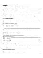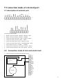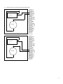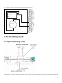
1
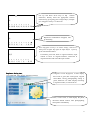
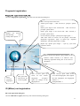
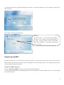
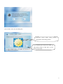
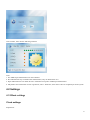
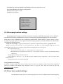
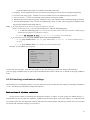
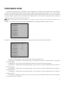
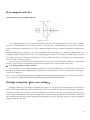
User Manual
AC300
Version:
1.0
1
Contents
1 Introduction...............................................................................................................................................5 1.1 Compiling intention .................................................................................................................................................5 2 Start-up .....................................................................................................................................................5 3 The initial interface...................................................................................................................................5 4 Structure and module of Application ............................................................................................6 4.1 user management.................................................................................................................................................... 11 4.1.1 User Registration................................................................................................................................... 11 Fingerprint registration.................................................................................................................................14 ID (Mifare) card registration ........................................................................................................................14 Original sound REC .....................................................................................................................................15 Photographing ..............................................................................................................................................16 4.1.2 Deletion of registration recording ...............................................................................................................18 4.2 Settings...................................................................................................................................................................19 4.2.1Basic settings................................................................................................................................................19 Clock settings...............................................................................................................................................19 Language settings.........................................................................................................................................20 Voice prompts ..............................................................................................................................................20 Volume mediation........................................................................................................................................20 Keypad tone .................................................................................................................................................20 4.2.2 Expert settings.............................................................................................................................................20 4.2.2.1 Checking interface settings ..............................................................................................................21 Whether to real-time photographing ....................................................................................................21 Whether to display photos....................................................................................................................21 Real-time fingerprint display settings ..................................................................................................21 4.2.2.2Delete all records...............................................................................................................................21 4.2.2.3 Delete all registered data ..................................................................................................................21 4.2.2.4 Restore the factory settings ..............................................................................................................21 4.2.2.5 Firmware upgrade ............................................................................................................................21 4.2.2.6 Daylight saving time settings: .......................................................................................................21 4.2.2.7 Keypad tone settings ........................................................................................................................22 4.2.3 Power supply management .........................................................................................................................22 Time starting up ...........................................................................................................................................22 Time power off.............................................................................................................................................22 Time dormancy ............................................................................................................................................22 Belling settings.............................................................................................................................................22 Free time settings .........................................................................................................................................23 Locking off key ............................................................................................................................................23 Time state transition.....................................................................................................................................23 4.2.4 Communication settings..............................................................................................................................23 Machine number ..........................................................................................................................................23 RS232...........................................................................................................................................................23 RS485...........................................................................................................................................................23 2
Baud rate ......................................................................................................................................................24 Ethernet network ..........................................................................................................................................24 IP address .....................................................................................................................................................24 Subnet mask .................................................................................................................................................24 Gateway address ..........................................................................................................................................24 Connection password ...................................................................................................................................24 Dynamic IP allocation..................................................................................................................................24 Back-stage address .......................................................................................................................................24 4.2.5 Recording settings.......................................................................................................................................25 Management recording alarm (alarm)..........................................................................................................25 Checking recording alarm (alarm) ...............................................................................................................25 Repeat affirmed time....................................................................................................................................25 4.2.6 Automatic detection ....................................................................................................................................25 4.3Access control function settings..............................................................................................................................25 4.3.1 Time sect settings ................................................................................................................................26 4.3.2 Grouping function settings ..................................................................................................................27 4.3.3 User door contact settings ...................................................................................................................27 4.3.4 Unlocking combination settings..........................................................................................................28 Basic settings of unlocking combination ................................................................................28 Unlocking combination settings ..................................................................................................29 4.3.5 Lock drive time ...................................................................................................................................30 4.3.6 Time delay of door contact .................................................................................................................30 4.3.7 Door contact switch settings ...............................................................................................................30 4.3.8 Duress alarm settings ..........................................................................................................................30 Duress fingerprint management ...........................................................................................................30 Password inspection alarm ...................................................................................................................31 Press-key help ......................................................................................................................................31 Alarm delay..........................................................................................................................................31 4.3.9 Wrong press of alarm ..........................................................................................................................31 4.3.10 Back function settings .......................................................................................................................31 4.3.11 Binding ID.........................................................................................................................................31 4.4 U disk management................................................................................................................................................32 4.5Alarm reset..............................................................................................................................................................32 4.6system information..................................................................................................................................................32 4.6.1 User registered number ...............................................................................................................................32 4.6.2 Fingerprint registered number.....................................................................................................................32 4.6.3 Checking record number .............................................................................................................................32 4.6.4 Management record number .......................................................................................................................32 4.6.5 Used memory ..............................................................................................................................................32 4.6.6 Residual capacity ........................................................................................................................................32 4.6.7 Device Information .....................................................................................................................................33 4.7 Query and pivot......................................................................................................................................................33 Checking recording Query ...................................................................................................................................33 Management recording query ..............................................................................................................................33 3
User registration inquiries ....................................................................................................................................33 5 Connection mode of external port ..........................................................................................................34 5.1 description of external port ....................................................................................................................................34 5.2 Connection mode of lock and electric bell...................................................................................................34 6 Networking mode ...................................................................................................................................36 6.1 Split networking mode ...........................................................................................................................................36 6.2 Networking mode of unity machine.......................................................................................................................37 6.3 Networking mode of fingerprint read head ............................................................................................................37 7 Transferring line mode illumination of terminal units network .............................................................38 7.1Connection mode chart of split transferring line.....................................................................................................38 7.2 Connection mode chart of transferring line of unity machine................................................................................39 8 Instruction of controller ..........................................................................................................................40 9 Basic concepts and explaination.............................................................................................................40 No trouble found ..........................................................................................................................................................40 Refuse to found ............................................................................................................................................................41 Permission rank............................................................................................................................................................41 Mode key .....................................................................................................................................................................41 Message notification ....................................................................................................................................................41 Host computer and slave ..............................................................................................................................................42 Daylight saving time(time zone settings) ...............................................................................................................42 4
1 Introduction
1.1 Compiling intention
Instruction for users
2 Start-up
When to start up, display firm LOGO and progress bar, collocate LOGO freely, enter original interface after start up, such
as:
Progress bar
3 The initial interface
After device links with power supply, the screen shows the first interface we call the initial interface, see figure,
the basic information is as follows:
Explanation: 1 Use larger font to display time.
2 Use other smaller font to display date, week, and other information.
3 The current status display: such as: sign in, sign off…
4 Or message information, how to display amount of rolling information.
5 Play colorful propaganda (advertising) page circularly.
Below the initial interface:
5
The Icon shows the main hardware
configuration, including whether or not
have camera, ID (MIFARE) Card,
fingerprint, SD card, network with power
supply mode, serial port and so on
Help tips column, shows the
current status or message
notification
1. Administrator enter into management mode,
1)Press MENU key,Equipment prompts " administrator, Please verify..."
2)Manager loggings in, administrators can use password, fingerprint or cards to log on
2. User checking
Allow user verify only in authentication mode (verification model is carried out in the access control settings), such as:
Press the number keys + OK is the serial number,
If the authentication mode is ID + password, it prompts “enter a password”,
If the authentication mode is ID + fingerprint, it prompts “press finger”,
3. Pressing finger or swiping card is generally direct verification
Please refer to the specific verification process for the verification process
4 Structure and module of Application
AC300 menu list
The first level
menu
The second level
menu
The third level
menu
Fingerprint
registration
User registration
RF card registration
User management
The fourth level
menu
Includes ID or
Mifare card
Original sound REC
Photographing
deletion of registration
recording
Device settings
System settings
Basic settings
clock settings
Language settings
Voice prompts
Volume mediation
6
Keypad tone
Checking interface
settings
Delete all records
Expert settings
Delete all registered
data
Restore the factory
settings
Firmware upgrade
Daylight saving time
settings
Function key settings
Total numbers of
managers
Password of super
manager
Sensitivity adjustment
Belling settings
Power supply
management
Free time settings
Beginning and end
of belling time
belling time
Belling music
power off
dormancy
Play colorful
propaganda
Time power off
Time dormancy
Time starting up
locking off key
timing state transition
machine number
Communication
settings
RS232
RS485
Baud rate
Ethernet network
IP address
Subnet mask
Gateway address
Connection
password
Dynamic IP
allocation
Back-stage address
7
Recording settings
Automatic detection
Management
recording alarm
(alarm)
Checking recording
alarm (alarm)
repeat affirmed time
Run all testing
Memory testing
LCD function
testing
Sound testing
Fingerprint Collector
testing
Keyboard testing
Real-time clock
Access Control
settings
Time sect settings
Grouping function
settings
User access control
settings
Combination mode
of groups
Validation mode of
groups
Time group
Validation mode of
time group
Other validation
modes
basic settings of
unlocking
combination
lock drive time
Time delay of door
contact
Door contact switch
settings
duress alarm settings
duress fingerprint
management
Password inspection
alarm
Key-press help
Alarm delay
settings
Wrong press of
alarm
back function settings
8
Binding ID
Download checking
records
Download
management
records
Download user
U disk management
information
Upload user
message
Upload message
notification
Upload mp3
Alarm reset
registered user number
registered fingerprint
number
Checking record
number
Management record
number
Used memory
Residual capacity
System information
User registered
number
Fingerprint registered
number
Checking record
number
Management record
number
Residual memory
Fingerprint capacity
Recording capacity
Management
recording capacity
Memory capacity
Device Information
Query and pivot
Standby time
Serial number
Manufacturer
Device name
Device model
Arithmetic version
Firmware version
Checking recording
9
query
Management
recording query
User registration
Inquiries
Press MENU key, the following “help column” prompts" administrator, Please verify..."
At this time, administrator can be passed through pressing fingerprints, inputting ID and password or swiping card to enter
the menu, such as authentication, only proved to be successful can enter the main menu.
See “8 validation process ”for verification process
1. Default the first as focus after entering the menu, display borders on the focus icon with.
2. The direction keys moves the focus to the appropriate icon, OK button can enter the corresponding submenu
3. Each icon has a number, press the corresponding number keys can directly enter this sub-menu
4. ESC can return to previous menu, ESC of the main menu key can return to the initial interface
5. Order shows the current menu and the full name of the selected sub-menu, it can show two levels of full name
6. Icon shows 4 Chinese characters at best, use the first three Chinese characters + “···“ substitute Chinese characters
more than four
7. Press MENU key states can back to the main interface in any menu states, enter the main menu interface at other main
interface states,
Start Input Method Editor in other states.
Currently, shows that selecting full
name of sub-menu
Icon
Show current menu
Tips of simple working method
10
4.1 user management
4.1.1 User Registration
Explanation:
1、The intermediate user: Refer to the general user, namely person who needs to verify identity because of some purpose,
such as person who opens the door through the device, or only those who check on work attendance.
2、The administrator: Operates all other work in addition to carry out advanced settings, registration or delete operation of
administrators at the same level, can maintain their own data
3、Super-administrator: can carry out all other operations including the deletion of his own and all other administrators
except super-0 administrator. After leaving factory, Equipment default with a super administrator (code as "00000",
password is "888888") can enter the menu for all operations. Password can be modified, but not to be deleted.
4、The equipment only register the intermediate user, the general manager may exercise any authority of the super
administrator
5、The same ID number can register up to 10 different fingerprints, fingerprint ID from 0 to start, followed by increments,
it can also be entered manually
6、After entering the registration menu and the real pre-registration, indicating the default ID (the last No. automatically
add 1), at this point, can enter a custom ID. (1-65535 5-bit)
7、Register fingerprint three times is success. In accordance with the message (voice and text), press the same finger (enter
the password twice) three times continuously. If it fails, indicating a failure, and prompts re-registration.
8、Choose ID card or Mifare card in accordance with the device configuration,
9、When register fingerprint or RF card, as there have such fingerprint or card number in the system, the system will
refuse to register, suggesting that "repeat fingerprint" or "duplicate cards"
Basic Information dialog box:
Once choose the user registration, can enter the following dialog box
11
Default empty
Password must be six figures, default 888888
Default empty, only the option (subject to sector
configuration files)
Default ordinary user, choose by the down
direction keys
Intermediate user
Administrator
Super administrator
1. The default code at this point: the last No. automatically add 1, the name is empty, there must be six figures, default
888888 password, the user-level is general
2. Number may input by users, if enter a password, the password and confirmed password must be the same,
3. If it is non-new registration, may targeted by this user ID, and then modify the name, password, user-level, department,
cards, photographs, original sound or fingerprint backup.
4. In any input state, F4 is a removal key (only removal of one character or Chinese character, that is, Backspace key
(Backspace)), it may delete all after a long press.
5. In any state of non-menu, F1 key is help key, it can display the help explanation of this state. Any key may
return.
Input Method Editor
Press MENU key to start Input Method Editor in relation to input, then press MENU key to switch input methods
including Pinyin, lowercase letters, uppercase letters, digital, clock input format.
F4 may back at this time. It may delete all after a long press.
T9 Bopomofo
mu nv nu ou
Appear this chart after pressing figure key 6 and 8
Here select Bopomofo combinations by pressing left
and right direction keys
Example: use ►to select ou
1 2 3 4 5 6 7 8 9
目 母 木 幕 穆 姆 亩 慕 姆 ▼
12
mu nv nu ou
欧
Use Up and down arrow keys to flip Chinese
characters, directly select the appropriate Chinese
characters by giving long-press of figure keys, example:
give long-press of key 1 to choose ou
2 2 3 4 5 6 7 8 9
欧 偶 藕 鸥 呕 殴 殴 瓯 沤 ▼
欧
Bopomofo combinations disappear, start
up Lianxiang
1 2 3 4 5 6 7 8 9 ▲
洲 阳 美 的 了 在 一 人 是 ▼
欧阳
1 2 3 4 5 6 7 8 9
光 春 台 关 的 了 在 一 是 ▼
Register dialog box:
Once identified, enter into the following interface
Give long-press of key 2 to select “Yang”, and have a
short-press of figure key again to input Pinyin. Cycle by
cycle until satisfied with it
If satisfied, press OK, back to original interface, input
content to focus of original interface, ESC-back to
original interface and cancel the input content
If Register several fingerprint, it shall display
these ones in green, RF card register, original
sound REC, having photographing setting is
green, otherwise it is white. Display according
to registered order, no more than ten
Photo, if user exists, it shall display the photo,
otherwise default cartoon, after photographing,
show photos immediately
13
Fingerprint registration
Fingerprint registration dialog box
Choose 1 Fingerprint registration,then enter into the following dialog box
Number 0-9. Increase
automatically,
may
modify when input 0…9
Have voice tips at the same time:
“Please press finger…” after succeed, it prompts: “please
leave”
Please press finger in the second time …after succeed, it
prompts: “please leave”
Please press finger in the third time…after succeed, it
prompts: “please leave”
No successful, it prompts: “please press finger again…”
After three times of success, do not prompt “successful
fingerprint registration” again. If repeat tips “repeated
fingerprint”. The three ellipse box is empty.
Repeat tips “please press finger…” cycle by cycle until
succeed or cancel
Before succeed, this button is gray, OK key is not
effective. When succeed, it is effective. The
following registration dialog box is the same as
this button
Show
real-time
fingerprint
Turn green after
each success, all
3 times together
After succeed, press up
arrow, no save current
fingerprint,
re-register
again. No change of the
fingerprint No.
After succeed, press down arrow,
save current fingerprint, then register
the next fingerprint, this fingerprint
number + 1
Example:00001--1
ID (Mifare) card registration
RF card registration dialog box
Choose 2 RF card to register, then may enter into the following dialog box
14
1, If the RF card has been registered and prompts, "RF card is in existence, whether or not to re-register?" Dialog box is
shown as below:
After confirm, enter into such dialog box:
Voice tips:
“Please show card…” after succeed, judge whether or
not repeat, if not, prompts “successful registration of
RF card”, if repeat, prompts “repeat card number,
please show card again…”, cycle by cycle until reach
success or cancel
Original sound REC
Through recording real voice of the person (usually my name), as voice prompts when verify, so that current staff can
further confirm the miscarriage of justice, thereby reducing the rate of miscarriage of justice. It is certainly faster and more
accurate than demonstrate their photos.
Original sound REC dialog box
Choose 3 original Sound REC, then may enter into the following dialog box
1, if the original sound has been recorded and prompts, "the voice had been recorded, whether or not to re-record?" Dialog
box is shown as below:
15
After confirm, enter into such dialog box:
Voice tips:
“Please say your name…” after succeed, prompts
“successful record”, if not successful, prompts
“ Please re-record”, cycle by cycle until reach success
or cancel
Display file name,
voice.wav/mp3
number
+
Photographing
The photo is 320*240*24b, size control within 16k,*.jpg form
Photographing dialog box
Choose 4 photographing, then enter into the following dialog box
1, If the user’s photo exists and prompts, "the photo had been recorded, whether or not to re-record?" Dialog box is shown
as below:
16
After confirm, enter into such dialog box:
Real-time camera before taking pictures,
show photos after taking pictures
If not satisfied, press the UP arrow ▲, may
take pictures again, at this time, re-voice
and re-text prompts.
17
Registration flow
Enter user registration
Enter dialog box system, show default No. (May modify) etc information
Y
Whether to modify No.
N
Whether to exist
N
Y
Orient according to No.
N
FP Enroll
ID(Mifare) card
Y
Y
Original
sound
Whether to exist
Photographing
record
Whether to exist
N
N
Save
4.1.2 Deletion of registration recording
Explanation:
1. After entering this menu, firstly prompts to input deleting a user ID
18
After confirm, enter into the following interface
Note:
1. No. 00000 super-administrator can not be deleted
2. The administrator may not delete other administrator, only can delete their own.
3. Super Administrators can delete all users’ information except No. 00000 super-administrator
4. May delete some information of user registration, select “ delete all” ,then remove the user completely from the system
4.2 Settings
4.2.1Basic settings
Clock settings
Explanation:
19
1. Including date and it’s form and time settings, default form is YY-MM-DD24H
2. Offer date forms which support at least 10 types,
YYYY MM DD YYYY-MM-DD、YYYY/MM/DD、
MM-DD-YYYY、 MM/DD/YYYY、
DD-MM-YYYY 、DD/MM/YYYY、
YYYYMMDD,
Language settings
Explanation: language that is displayed on the screen menu of setting fingerprint machine (voice also should be amended
accordingly, but currently do not support).Default simplified Chinese
Voice prompts
If choose “yes”, there has corresponding voice hint on the device. If choose “no”, only have “DD” buzzer.
The voice document is mp3 or wav format, approximately have:
1. Successful verification:
May play if having recorded voice of the user, otherwise play user number hint such as “0001”, the voice of the number
must be speech synthesis of real people, prior input 0-9 numerical voice.
2. Failing verification:
“Number absence”, “please press finger again”, “please replay card”, “please input password again”.
Volume mediation
Namely regulation of sound volume
Keypad tone
If choose “yes”, press key has sound, otherwise not.
4.2.2 Expert settings
Display this menu only when the super-administrator access to.
20
4.2.2.1 Checking interface settings
Whether to real-time photographing
If choose "Yes", you have to set up to preserve the ratio of real-time photographing which are as follows:
1.0: no save
2.30%
3.60%
4.100% save all
Whether to display photos
Real-time fingerprint display settings
When choose "yes" in the registration of fingerprints and fingerprint mode authentication, it shows
corresponding true fingerprint image. Choose "No", it does not show.
4.2.2.2Delete all records
Delete all validation records.
4.2.2.3 Delete all registered data
Delete all registration records (delete all users, only leave 00,000 user which the system default)
4.2.2.4 Restore the factory settings
Restore all settings message to the state of leaving factory (default state).
4.2.2.5 Firmware upgrade
This option can upgraded the terminal unit, select upgrade file of U disk, Click OK to upgrade.
4.2.2.6 Daylight saving time settings:
In order to meet the needs of daylight saving time of some countries, regulate an hour faster on XX minute
XX hour XX day XX month, when on XX minute XX hour XX day XX month, regulate one hour slower.
The beginning of daylight saving time – the beginning time for implementing the daylight saving time
21
The end of daylight saving time - the end time for implementing the daylight saving time
Correction time - different with the current time
Example: The current time is 16:07 , April 9
The beginning of daylight saving time: Set for April 1
The end of daylight saving time: Set for May 1
Correction time: set to 1 hour
Back to the checking work attendance interface, display the time :2009-4-8 16:07
4.2.2.7 Keypad tone settings
Function keys can be set as features include: overtime registration, off duty registration, work registration, view system
information, alarm, belling, query records, go-off, entering, return, out, overtime work leaving.
Default definition state transition of the system
F1: work attendance, F2: check back from work, F3: overtime
attendance, F4: signed back to overtime work.
Here the function key is shortcut, you can switch directly to the needed state through these function keys without the need
to do those tedious operation.
4.2.3 Power supply management
Time starting up
The equipment automatically opens within specified time. (Run the function only in power off and time dormancy state)
Time power off
The equipment automatically closes within specified time. (All other modules are closed except the CPU core), press the
power button or to the boot time, it start up. (In sleep mode)
Time dormancy
The equipment automatically enters sleep mode within specified time. (All other modules are closed except the CPU core
and key board), press any key to wake-up equipment in working condition.
Belling settings
Belling Settings include beginning and ending time, duration, music.
Belling can be set 8 kinds of times, you can set up time of timing belling in accordance with the needs, when arrive at the
set time, the fingerprint machine will automatically ring, then to reach the length of ringing, it automatically cut-off. If
ringing time is 0, the ring is closed. Otherwise, ring according to setting time and length.
Two ringing ways:
22
1) from the loudspeaker of machine itself.
2) Connect electric bell with a fingerprint machine, when arrive at the set time, the machine shall send out a relay signal to
trigger bells ring.
Free time settings
1. Free means that users do not use terminal equipment
2. Including transit state choice and free time settings, the two options are interrelated, when the free time to 0, the free
setting function is turned off; when the free time is non-0 value (in minutes ), such as 1, then if there is no any operation
within 1 minute, the system will enter free state of the specified settings
3. Free transition state include: sleep and shutdown
Locking off key
Failure to power button: “yes”- failure to shutdown button
“No”-effective to shutdown button
Time state transition
State transitions: when use roll machine, it require to keep a record of roll status in different time, after this setting,
when arrive time that user set, the machine will automatically convert to the status of rolling. Display the current rolling
state in the current rolling interface.
At least include: sign in, sign off, overtime sign in, overtime sign off etc four states and at least six time sects
4.2.4 Communication settings
Machine number
Number that the machine in the LAN, range from 1 to 255
RS232
Whether or not to use RS232 for communication
RS485
Whether or not to use RS485 for communication
23
Baud rate
Default 9600, set up five options: 9600,19200,38400,57600,115200.
Ethernet network
Whether or not to open Ethernet communication, if choose "Yes", you should also set the following parameters:
IP address
Default IP is 192.168.1.201, adjust in accordance with demands
Subnet mask
Default subnet mask is 255.255.255.0, adjust in accordance with demands
Gateway address
Default gateway address is 192.168.1.1, adjust in accordance with demands
As the default communication mode: whether or not to use TCP / IP protocols for communications.
Connection password
The system default password is 0, that is no password, you can set, if set password, when connect you have to offer a
password. The number of connection password up to eight digits at most.
Dynamic IP allocation
Back-stage address
PC back-stage address is the address of upper computer, it can control the host computer of terminal unit, there is
need to enter the IP address of this host device
24
4.2.5 Recording settings
Management recording alarm (alarm)
When the value of remaining management record capacity arrives at setting standard, the equipment will automatically
prompt a warning message of remaining record;
Checking recording alarm (alarm)
When the value of remaining record capacity arrives at setting standard, the equipment will automatically prompt a
warning message of remaining record;
Repeat affirmed time
In the set time range (unit: minutes), such as there has existed one person's attendance records, then the second
passed checking in result will not be saved.
4.2.6 Automatic detection
Test system components. When equipment fails, it has advantage to analyze failure reason, thus maintain the
equipment quickly and easily.
Including testing memory, LCD screen, voice, fingerprint collector, keyboard and the clock, in the testing process,
should ensure the stability of power supply, or else they might damage the system hardware, especially during the
storage testing process.
Run all tests
Memory test
LED function test
Voice test
Fingerprint collector test
Key board test
Real-time clock
MP3 function
4.3Access control function settings
Introduction:
25
Settings for each user is compose of one sub-group, group time sect and user time sect.
Grouping means assign a group of users to some group, for example, Group 1, Group 2, etc.;
choose three set time sect at most in group time sect, there is "or" relationship among these three time
segment(that is, to meet any of the three is ok);
choose three set time sect at most in user time sect, there is "or" relationship among these three time
segment; see "User Access Control settings" for relationship between the using group time sect and user
time sect.
In short, the conditions for registered users to open the lock:,
1: The group that user located must be in the unlocking combination (if you implement unlocking
combination settings, it demands verify with personnel of other groups in the same unlocking portfolio,
then you can open the lock);
2: the current unlocking time should be in any effective time zone of the user time sect;
System default the new registered user as the first group, and default grouping for the first group, the
time sect of default group is "1". In the case of leaving factory state of the Group 1 and time 1, default
new registered user is to unlocking state (If users modify the settings related to access control, the
system shall change with the diversification by users). If there is no grouping of users in the unlocking
combination settings, the user can only check on work and can not unlock.
4.3.1 Time sect settings
Defines unlocking time each day in one week, it is the minimum time unit of access control settings. The
whole system can define up to 50 time sects one day. Each time sect defines 7 time sects, they are from
Monday through Sunday, each interval has effective period of time of 24 hours per day. Each user can set a
maximum of three time sects, three sects are "or" relationship, time is effective as long as the verification
time is able to meet one of three. The format of each time interval: HH: MM-HH: MM, namely accurate
to minutes in accordance with the 24-hour system.
The ending time is smaller than the beginning time (23:57 - 23:56) that means the prohibition of the
whole day, The ending time is bigger than the beginning time (00:00 - 23:59) that means this sect is
effective.
The effective unlocking time for users: open all day (00:00-23:59) or the ending time is bigger than
the beginning time in this time sect.
Example 1: the system default time sect 1 for an opening day that means default leaving factory state
(that is, new registered users need to unlock).
Time sect 1 definition
Sunday 00:00-23:59
Monday 00:00-23:59
Tuesday 00:00-23:59
Wednesday 00:00-23:59
Thursday 00:00-23:59
Friday 00:00-23:59
Saturday 00:00-23:59
Example 2:
26
Not allowed to enter on Saturdays and Sundays, these two days have a rest;
enter from Monday to Friday at working hours
Working hours: 08:30-18: 00;
Settings are as follows:
Time sect 2 definition
▲
Sunday 23:57-23:56
Monday 08:30-18:00
Tuesday 08:30-18:00
Wednesday 08:30-18:00
Thursday 08:30-18:00
Friday 08:30-18:00
Saturday 23:57-23:56
4.3.2 Grouping function settings
Grouping function settings can divide users into several parts, and different groups can be combined
into different unlocking combinations in order to facilitate the grouping management of access control.
Such groups can be combined as lots of unlocking combinations. System defines 5 groups: group 1, group
2, group 3, group 4, group 5. New registered users belong to group 1 by default, but these users also can be
re-assigned to all other groups.
Group time sect settings:Set group unlocking time, choose the completed setting number in group time sect.
Default to use time sect of group 1 for new registered user, but when user resets affiliated group, the user uses
corresponding group time sect, so firstly it needs to define the default time sect of each group.
Note:1System default group 1
Time sect choose to define number “1”.(default unlocking for new registered user)
The default time sect of group 2 has 1 time sect,may set three time sects at most, the relationship among
them is “or”.
Example group 2 settings of default time sect
group2 efficient in time sect :1、8、40 and the group validation mode is fingerprint, it also may choose other
defined time sect.
Group2 default time sect 01:08:40-fingerprint
Group validation mode settings
Set default validation mode of the device. Namely choose any kinds of combination mode of ID number, fingerprint,
password, ID (Mifare) card, default single fingerprint, there are 6 types to select. Only can choose one type. See
authentication mode for details
4.3.3 User door contact settings
Set affiliated user group, time sect of the using group, user time sect, validation mode of the using group,
27
personal authentication mode in accordance with needs of the user.
□ grouping:divide registered users into several parts (according to roles) in order to facilitate management,
□ time sect of the using group:whether or not to use default time sect of affiliated group by the user,
□ time sect of users:set time of unlocking, namely choose the set time number,
□ authentication mode of the using group:Whether or not to use validation mode of affiliated group by the user.
□ Personal authentication mode:Choose an authentication mode, no other than using group validation mode,
the personal validation mode shall effective.
Note:1、the relationship between the time sect of using group and the user time sect
whether or not be effective only on the following user time sect in “ time sect of the using group” :
1) If the time sect of the using group is “yes”, the user time sect shall evaluate as the time sect number of affiliated group
automatically( the group time sect should be set firstly). ”
2)if modify the time sect of users, the time sect of using group is ‘No” automatically;
2、the relationship between using group validation mode and personal validation mode
1)If the group validation mode is “yes”, the group validation mode is effective, the personal validation mode is
invalid
2) If the group validation mode is “no”, the user use personal validation mode.
Example: set user 00001 into one group.
User 00001
Group
Time sect of using group
Time sect 1
Time sect 2
Time sect 3
Validation mode of using group
Validation mode
1
yes
1
8
40
yes
FP
Use the time sect of group 1(here the time number of user shall change into group time number automatically),
User uses group validation mode, in spite of personal authentication mode is which one, it depend on the group validation
mode
4.3.4 Unlocking combination settings
The following two are mutually exclusive, you can choose one only, none but the basic settings of unlocking combination
is “No”, the unlocking combination settings shall effective.
Basic settings of unlocking combination
Set the person number of unlocking the fingerprint machine, no matter in which group, the default setting is 1,
indicate that only one user pass the validation, it shall emit lock control signal, such as the setting is 3, it indicates three
users need to pass, then the fingerprint machine shall emit lock control signals, and intervals of each one is no more than
30 seconds. The maximum setting is no more than 5.
28
Unlocking combination settings
Set different unlocking group combinations, each combination is composed of the different group. The unlocking
combination use group number directly, without regard to validation order of every group. Such as “ 123” means 1 group,
2 groups, 3 groups, it demands at least one user in each group to validate together that can open the lock, “4” means one
user of the single 4 groups passes the validation, then to open the lock.. at one time, the system may define 10 kinds of
combinations at most, only one of them can pass is ok.
note:The unlocking combination of initial system default is “1” ( Namely, any person in group 1 can open, default the new registered user
can open).
Example 1: No setting (leaving factory state), the system default group 1 is unlocking combination 1, others are empty,
Definition of Unlocking combination
Combination1
1
Combination 2
Combination 3
Combination 4
Combination 5
Combination 6
Combination 7
Combination 8
Combination 9
Combination 10
Example 2:If use certain groups to release lock, set these groups in unlocking combination definition,
Definition of Unlocking combination
Combination 1
123
Combination 2
4
Combination 3
24
Combination 4
45
Combination 5
15
Combination 6
Combination 7
Combination 8
Combination 9
Combination 10
From above scheme setting we can see that all set 5 unlocking combinations,
combination 1:When person of each group (group 1, 2, 3) pass time sect of the user authentication to be effective,
the door will open,
combination 2:Only 1 person (person belongs to group 4) be on the scene, the door will open,
combination 3:When person of each group (group 2, 4) pass time sect of the user authentication to be effective,
the door will open,
combination 4:When person of each group (group 4, 5) pass time sect of the user authentication to be effective,
the door will open,
combination 5:When person of each group (group 1, 5) pass time sect of the user authentication to be effective,
the door will open,
To sum up, in unlocking combinations, firstly, staff of each group in portfolio should have the same effective
period of time, the door will open.
29
Explanation:No passing time zone of validation
□ unselected time zone number of user,
□ unselected time zone number of group default time zone(when using group time zone),
□ the validation time for user does not exist in any setting time zone;
□ define time zone as forbiddance;
Note:if the time zone set by user is not passed:
□ answer for above combination 2, it appears prompt that user of “Illegal sub-portfolio ” can not open lock, but may check on work
attendance.(in group 4, there are other users meet unlocking qualification, the combination 2 may open the lock)
□ Answer for above combination 1,3,4,5, it appears prompt that user of “Illegal sub-portfolio” can not open lock, but may check on work
attendance.
Note:1. when set combination 245, no permission for setting combination 24、combination 25、combination 45.
2. If you want to make all registered users can not unlock, set the whole 10 combinations to empty.
4.3.5 Lock drive time
The lock drive time length means time difference between validated time and starting electric lock that after machine
validates fingerprint. Take 0.5 seconds for the smallest accurate unit. The Largest set is 5s
set to "0" means to close lock control function.
4.3.6 Time delay of door contact
Indicates delay time for inspecting door contact after open the door, namely after delay time to inspect door state (open or
close), if there is difference between the door contact state and the set state, it gives an alarm. This time is the time delay of door
contact, the unit is “s”
4.3.7 Door contact switch settings
Include three kinds: No, normally opened type, normally closed type;
No: no use of door contact switch;
Normally opened type: if the door is open, the lock should be open, otherwise it shall appear door contact alarm after
passing the delay time;
Normally closed type: if the door is closed, the lock should be same, otherwise it shall appear door contact alarm after
passing the delay time.
4.3.8 Duress alarm settings
If register duress fingerprint, it shall alarm automatically after passes this fingerprint in
order to prevent somebody from compelling to open the door.
Duress fingerprint management
Register duress fingerprint:Register new fingerprint as duress fingerprint
30
Appointment of duress fingerprint:Change registered fingerprint into duress fingerprint
Cancel duress fingerprint:Cancel single duress fingerprint
Cancel all:Cancel all duress fingerprints
User specially registers a new fingerprint or appoints a registered one existed in fingerprint machine as duress fingerprint.
In any cases, after compare with these fingerprints, it may appear duress alarm.
Password inspection alarm
Open or close such alarm function
Press-key help
If choose “yes” to press-key help, give a long press on“▼” key( more than 3 seconds)to produce SOS; after press “▼”
key( no more than 3 seconds) , then fingerprinting or press ID number, if succeed in identity, it shall appear duress alarm
at one time;
If choose “no” to press-key help, give a long press on“▼” key is out of operation.
Alarm delay
Defines automatic alarm time: after appears duress alarm signal, input alarm signal indirectly, it can be defined, and
appear alarm signal automatically in a minute (0-255 seconds).
4.3.9 Wrong press of alarm
Set times of wrong press of alarm: when validation is not passed and the wrong times reach the set value, it shall
alarm. 0 is wrong press and have no alarm (infinite and many times), otherwise you may set 1-9 times, default 3 times.
4.3.10 Back function settings
Judge whether or not to back in accordance with the latest in and out records, in and out must be matched. It demands
support of host computer and slave (see host computer and slave).
Example:Somebody wants to go out,
⑴ if his latest record is not go in, the machine shall prompt “refuse back” and refuse to open the door.
⑵ if his latest record is go in, he can open the door after authenticate the fingerprint.
“Back in” and “back in and out” have similar logic.
4.3.11 Binding ID
Use on the connection of extensions, communicate with extension in the case of the binding number is right.
31
4.4 U disk management
USB flash disk management ▼
►Download validation records
Download management records
Download user information
Upload user information
Upload message notification
Upload mp3
4.5Alarm reset
When the machine is not alarm, the menu has no option of alarming, only the machine begin to alarm, option
“alarm reset” shall appears in the menu, select the option to lift the current alarm status.
4.6system information
4.6.1 User registered number
4.6.2 Fingerprint registered number
4.6.3 Checking record number
4.6.4 Management record number
4.6.5 Used memory
4.6.6 Residual capacity
Registered user number
Registered fingerprint number
Checking record number
Management record number
Residual memory
32
4.6.7 Device Information
Fingerprint capacity
Note capacity
Management record capacity
Memory capacity
Leave factory date
Serial number
Manufacturer
Device name
Device model
Arithmetic version
Firmware version
4.7 Query and pivot
Checking recording Query
Support query according to date, number, name. Display in report forms
Management recording query
Support query according to date, number, name. Display in report forms
User registration inquiries
Support number, fingerprint, ID (MIfare) card query. Display in report forms
33
5 Connection mode of external port
5.1 description of external port
Combination mode of links:
1、 RS232 connection method—RS232R、RS232T、GND
2、 RS485 connection method—RS485A、RS485B
3、 connection mode of Wiegand—GND、DATA0、DATA1
4、 connection mode of the bell—BELL-、BELL+
5、 connection mode of OUT switch—BUTON、GND
6、 connection mode of door contact—DOORSENSOR、GND
7、 alarm connection mode—ALARM+、ALARM8、 connection line of the lock—LK-COM、LK-NO、LK-NC
9、 connection line of the bell—BL-COM、BL-NC、BL-NO
5.2 Connection mode of lock and electric bell
1、connection mode of normally electrified closed lock
Power supply
+
adapter
12V
+
LOCK
-
34
2、connection mode of normally electrified opened lock
Power supply
+
adapter
12V
+
LOCK
-
3、connection mode of normally electrified closed electric bell
Power supply
+
adapter
12V
+
LOCK
-
35
4、connection mode of normally electrified opened electric bell
Power supply
+
adapter
12V
+
LOCK
-
6 Networking mode
6.1 Split networking mode
Explanation:Connection mode of extensions, network cable provides with the power supply of terminal unit, the terminal
36
unit need no Power cell
6.2 Networking mode of unity machine
6.3 Networking mode of fingerprint read head
37
7 Transferring line mode illumination of terminal units
network
1, Terminal equipment has two transferring line methods, one is split transferring line mode, the other is transferring line
mode of unity machine.
2, In split transferring line mode, communicating with upper computer only has two modes, one is TCP / IP, the other is
the RS485. Split transfer mode for networking mode of the split. The network connection process in split mode is network
input ◊controller ◊terminal unit. RS485 communicates directly with upper computer by terminal unit.
3、the transfer mode of unity machine is used in networking mode of unity machine and Wiegand. In the mode of unity
machine, it can communicate with upper computer by TCP/IP、RS485、RS232. When RS485 and RS232communicate
with upper computer, RS485 and RS232 can not be used at the same time
4、RS485can communicate with upper computer, at the same time, it can be used on back function. When user uses RS485
on back function, it can not be connected with upper computer.
7.1Connection mode chart of split transferring line
485A/TX+
485B/TX38
232R/RX+
232T/RX-
232T/WG1
232T/WG0
7.2 Connection mode chart of transferring line of unity machine
485A/TX+
485B/TX-
232R/RX+
232T/RX-
232T/WG1
232T/WG0
39
8 Instruction of controller
8.1explanation of controller external port chart
Method combinations of ports
1、 OUT TCP output network cable, this port connects with terminal directly
2、 IN TCP input network cable,this port connects with Router directly
3、 Connection mode of out switch—BUTON、GND
4、 connection mode of door contact—DOORSENSOR、GND
5、 connecting line of alarm—ALARM+、ALARM6、 connecting line of electric lock—LK-COM、LK-NO、LK-NC
7、 connecting line of electric bell—BL-COM、BL-NC、BL-NO
note:NO—normally opened connection
NC—normally closed connection
Please refer to 5.2 for the connection mode of electric lock and electric bell
9 Basic concepts and explaination
No trouble found
Fingerprint device identifies the fingerprint of user A to user B,
40
Refuse to found
Fingerprint device refuses the registered fingerprint.
Permission rank
Serial fingerprint machine has 3 permission levels:
□ User:indicates those who need to establish identity because of some purpose, such as open the door though the
device, or record their in and out records
□ Administrator:Implements all other operation except carrying through advanced settings and register users that
they have power more than administrator (include administrator).
□ Super administrator:User that can visit all system functions and alter all settings of the system.
Explanation:registrar can register administrator and super administrator if having no registration of super
administrator, at the same time, if there is no super administrator, the administrator may register super administrator;
if have super administrator, the junior administrator can not register senior administrator.
Mode key
When using fingerprint, different event corresponds to different state, such as work sign in, off sign in, overtime sign
in, out, back etc states according to clock in conditions. It also can be divided into go-in, go-off states according to in
and out condition of door contact machine.
Some key board has 4 function key (F) or direction key, they all can be as state key to set current status. But these
modes are manual, when you need to use some status, you should press corresponding button. In order to reduce manual
operation, you may set transferring function (timing status), when arrive at some set time, the machine shall transfer into
current state and display in initial interface.
Message notification
It is divided into public and private message. Set on back-stage of System, and then upload to the fingerprint machine,
when start rolling machine, you can see the short message to the public about attendance, it is all along exist. After user
input validation fingerprint, there will prompt short message for private people so as to reduce the workload of staff and
greatly improve work efficiency.
Send message by aiming at somebody, If an employee’s birthday is on October 20, you can set up software in the
background on October 20 which issues to him a short message "Happy birthday to you", then upload to the machine,
after the staff validates the fingerprint authentication on that day, this message will be displayed on screen.
Send message by aiming at many people, such as hold company meeting on June 19, you can set up in the
background, then upload to the machine, and the screen shall display "about XX Conference, Room XX, please participate
at XX (time) on that day.
There are two ways for transmitting information, first, one is direct transmission by connecting back-stage system with
fingerprint machine, and the other is transmitted from the U disk.
41
Host computer and slave
1、introduction of host computer and slave
Two machines control one lock, install one machine in the door (hereinafter referred to as the "host"), install the
other one out the door(hereinafter referred to as "slave"), at the same time, 2 machines may control the lock only the host
connect with the lock. Consequently, solve trivial connection problem of using 2 traditional machines on controlling one
lock.
Fingerprint identification, complete to verify user permissions in the host computer, the computer also keep records, slave
is fingerprint head or reading module only, carry through fingerprint collection, card reading, and shall need to verify the
information, then sent it to the host. Consequently, solve chaos problem of software on managing user information and in
and out records of 2 relative machines.
The host and slave machine also has back capabilities, in and out records must be matched, otherwise, it can not open
the door, so prevent people who followed by others from entering the door, and prevent the security risks.
2、work principle of host computer and slave
Host computer:Carry through fingerprint registration, fingerprint authentication, user permission settings, user
permission verification, receive fingerprints or card information collected from extension, and then validate and bring the
results back to the slave.
Slave:Only as a fingerprint read head, carry through fingerprint collection, read card, and send message which need to be
verified to the host computer, the host can choose whether to display the test results of slave.
Daylight saving time(time zone settings)
Daylight Saving Time, also known as "Daylight Saving Time", it is a system which regulate local time artificially in
order to save energy, during the implementation of this system, the adopted time known as the "daylight saving time."
Generally, in summer day comes early, so people regulate one hour ahead of time, then you can get up and sleep early to
reduce amount of lighting and make full use of light resources, thereby saving lighting electricity. In autumn, move clock
back. Different countries adopt specific regulation about daylight saving time. At present, nearly 110 countries implement
daylight saving time each year.
42