1
Aquarius
5000 Series
USER'S MANUAL
0311374 Rev B
Issue : January 1999
Notice:
The accuracy of this receiver is not only dependent on its performance but also on various external
factors (installation and environmental conditions, handling, use, etc.).
Therefore, it should be used as an aid to navigation rather than a substitute for a navigator's skill
and judgment.
This DSNP receiver is a reliable shipmate that will help you to make vital decisions in critical
situations, but don't let them allow yourself to believe this relieves you of customary prudence and
navigational care.
FCC statement (USA)
The United States Federal Communications Commission (in 47 CFR 15.105) has specified that the
following notice be brought to the attention of users of this product:
This equipment has been tested and found to comply with the limits for a Class B digital device,
pursuant to part 15 of the FCC Rules. These limits are designed to provide reasonable protection
against harmful interference in a residential installation. This equipment generates, uses and can
radiate radio frequency energy and, if not installed and used in accordance with the instructions,
may cause harmful interference to radio communications. However, there is no guarantee that
interference
will not occur in a particular installation. If this equipment does cause harmful interference to
radio or television reception, which can be determined by turning the equipment off and on, the
user is encouraged to try to correct the interferences by one or more of the following measures:
- Reorient or relocate the receiving antenna.
- Increase the separation between the equipment and the receiver.
- Connect the equipment into an outlet on a circuit different from that to which the receiver
is connected.
- Consult the dealer or an experienced radio/TV technician for help.
The user may find the following booklet, prepared by the Federal Communications Commission,
helpful: How to identify and Resolve Radio/TV Interference Problems. This booklet is available
from the U.S. Government Printing Office, Washington, DC. 20402 , Stock No. 004-000-00345-4.
Use of a shielded cable is required to comply within Class B limits of Part 15 of FCC Rules.
Pursuant to Part 15.21 of the FCC Rules, any changes or modifications to this equipment not
expressly approved by DSNP may cause harmful interference and void the FCC authorization to
operate this equipment.
DSNP makes no warranty of any kind with regard to this equipment, including, but not
limited to, the implied warranties of merchantability and fitness for a particular purpose. DSNP
shall not be liable for errors contained herein or for incidental consequential damages in
connection with the furnishing, performance, or use of this equipment
This manual contains proprietary information which is protected by copyright. All rights are
reserved. No part of this document may be photocopied, reproduced or translated into another
language without the prior written consent of DSNP.
The information contained in this manual is subject to change without notice.
Aquarius 5000 Series User’s Manual
How to use this Manual
How to use this Manual
This manual is designed to encompass the whole 5000 series of
DSNP Aquarius products and therefore reflects the modular design
of the series.
We deliberately made the choice of extending the modular concept
of the Aquarius series up to its documentation for we think this is the
best way to preserve the consistency of the whole set of technical
information proper to this series of products.
As a consequence, you may not need to read all the manual if your
purchase does not include the options described from section 2 to
section 6.
This user's manual is made up of the following sections and
appendices:
-
DSNP
Section 1, Basic operating instructions for the 5000
series, should be read first as this section covers the whole
installation procedure and the first-level operating
instructions.
For most cases of use, only the reading of the first two
chapters of section 1 (Unpacking & installation, Getting
started) is required.
For users who wish to know more about their receivers, a
second level of operating instructions is provided in section
1, involving the use of a control computer and DSNP
proprietary commands.
Section 1 also includes a brief description of the receiver
front and rear panels and a troubleshooting guide. Section
1 is common to all the Aquarius products.
Aquarius 5000 Series User’s Manual
-
Section 2, Processing options, contains the necessary
information to operate your receiver in the desired
processing method (DGNSS, WADGPS, KART, LRK). It is
assumed that the receiver has reached the operational
status described in section 1. In fact only the KART and
LRK methods are options as the DGNSS and WADGPS
methods are available in all the receivers of the 5000
series.
-
Section 3, DGNSS Data link option, describes the
hardware required for a DGNSS Data link and how to
operate this option.
-
Section 4, Extended I/O option, describes the hardware
required to give the receiver new I/O capabilities (1pps,
RS422 port, 10-MHz clock input, external event).
-
Section 5, Station firmware option, provides all the
information needed to implement and use this option.
-
Section 6, Station Installation Kit option, tells you how to
install a base station using this optional kit.
- Appendix A is a short introduction to the GNSS system.
- Appendix B reviews all the products of the 5000 series,
from the simplest equipment up to the most sophisticated
one.
- Appendix C provides a complete description of all the
DSNP NMEA0183-compliant proprietary commands.
- Appendices D and E describe the GPS raw data issued by
the receiver, respectively in the SVAR format and SBIN
format. Appendix F describes the default messages of
computed data
- Appendix G presents the DSetPack software, including the
Win Comm communication software.
DSNP
Aquarius 5000 User’s Manual
Table of Contents
Table of Contents
1. Basic operating instructions for the 5000 series..............1-1
Introductory Notes ....................................................................... 1-1
Unpacking and installation .......................................................... 1-2
Unpacking...................................................................................... 1-2
GPS antenna installation ............................................................... 1-3
Receiver installation ...................................................................... 1-4
Connections................................................................................... 1-6
Receiver description.................................................................... 1-7
Front Panel .................................................................................... 1-7
Rear panel ..................................................................................... 1-9
Getting your equipment started ................................................. 1-10
Basic connections........................................................................ 1-10
PC connection ............................................................................. 1-10
Getting started ............................................................................. 1-11
Editing the estimated position...................................................... 1-15
Editing the receiver time & date................................................... 1-16
Checking the fix mode used ........................................................ 1-17
Checking the type of position solution used for navigation.......... 1-18
Work sessions........................................................................... 1-19
Theory of operation...................................................................... 1-19
A few programming examples ..................................................... 1-22
Usual changes made to the receiver configuration
from the Control computer ........................................................ 1-26
Enabling/disabling all data outputs .............................................. 1-26
Editing the settings of a serial port .............................................. 1-27
Editing/adding the definition of a computed data output.............. 1-28
DSNP
i
Aquarius 5000 User’s Manual
Table of Contents
Editing the definition of a GPS raw data output ........................... 1-30
Editing the definition of a pseudorange-data output .................... 1-31
Editing the navigation mode currently selected ........................... 1-32
Editing the filtering time constant applied to speed ..................... 1-33
PCMCIA reader ......................................................................... 1-34
Inserting a PCMCIA card ............................................................. 1-34
Removing a PCMCIA card........................................................... 1-35
PCMCIA file organization............................................................. 1-35
PCMCIA control ........................................................................... 1-35
Reading the amount of free memory ........................................... 1-36
Listing all the files present on a card ........................................... 1-37
Loading a configuration from a card ............................................ 1-38
Checking receiver operation from the Status Display ............... 1-39
Screen No.0: Operating Status.................................................... 1-41
Screen No. 1: Error report ........................................................... 1-42
Screen No. 2: Position solution ................................................... 1-43
Screen No. 3: Time information ................................................... 1-44
Screen No. 4: GNSS reception status ......................................... 1-45
Screen No. 5: Information about sessions................................... 1-46
Screen No. 6: Information about corrections ............................... 1-47
Screen No. 7: Differential corrections.......................................... 1-48
Screen No. 8: Firmware Options installed ................................... 1-49
Screen No. 9: Hardware and Software identification ................... 1-50
Rear panel Connectors ............................................................. 1-51
RS232 cable ................................................................................ 1-54
Troubleshooting......................................................................... 1-55
Front Panel Indicators ................................................................. 1-55
Error report .................................................................................. 1-56
Error families ............................................................................... 1-56
Error classification ....................................................................... 1-57
Error list ....................................................................................... 1-58
ii
DSNP
Aquarius 5000 User’s Manual
Table of Contents
2. Processing options ............................................................2-1
DGNSS........................................................................................ 2-1
Introduction.................................................................................... 2-1
Software installation ...................................................................... 2-1
Implementation Procedures........................................................... 2-2
Typical programming example....................................................... 2-7
Implementing Conventional DGNSS ........................................... 2-11
WADGPS .................................................................................. 2-17
Introduction.................................................................................. 2-17
Software Installation .................................................................... 2-17
Implementation Procedure .......................................................... 2-18
QA/QC....................................................................................... 2-22
Introduction.................................................................................. 2-22
Software Installation .................................................................... 2-23
Implementation Procedures......................................................... 2-23
Internal Variables containing QC results ..................................... 2-26
KART/LRK................................................................................. 2-28
KART ........................................................................................... 2-28
LRK.............................................................................................. 2-31
Implementing the KART and LRK processing modes ................. 2-33
3. Data Link options...............................................................3-1
UHF Data link option ................................................................... 3-1
Introduction.................................................................................... 3-1
Data link specifications .................................................................. 3-2
Installation ..................................................................................... 3-4
Typical programming steps ........................................................... 3-8
UHF Datalink Programming Examples ........................................ 3-10
Transmitted Data Blocks ............................................................. 3-18
DSNP
iii
Aquarius 5000 User’s Manual
Table of Contents
4. Extended I/O option .........................................................4-1
Installation ................................................................................... 4-1
RS422 port (port C) ..................................................................... 4-1
10 MHz external oscillator input .................................................. 4-3
1 pps output................................................................................. 4-3
External Event input .................................................................... 4-4
5. Station Firmware option....................................................5-1
Foreword ..................................................................................... 5-1
Installation ................................................................................... 5-2
Equipment required ....................................................................... 5-2
Program files ................................................................................. 5-2
Installation instructions .................................................................. 5-3
Introduction to operating Instructions ............................................ 5-4
Introduction to the Station Control software ................................ 5-5
Palmtop display ............................................................................. 5-5
Keys and menus............................................................................ 5-5
Getting started........................................................................... 5-10
Station Control........................................................................... 5-12
Antenna ....................................................................................... 5-12
Position........................................................................................ 5-13
Transmitter .................................................................................. 5-16
Average position.......................................................................... 5-17
File Management....................................................................... 5-19
PCMCIA card............................................................................... 5-19
Raw Data ..................................................................................... 5-20
Sessions ...................................................................................... 5-21
SVs............................................................................................ 5-25
Visible Constellation .................................................................... 5-25
Deselection.................................................................................. 5-27
iv
DSNP
Aquarius 5000 User’s Manual
Table of Contents
Coordinate System Used .......................................................... 5-28
Datum .......................................................................................... 5-28
Projection..................................................................................... 5-29
Change to WGS84 ...................................................................... 5-29
Load Geodesy ............................................................................. 5-30
Local Grid .................................................................................... 5-31
Height correction ......................................................................... 5-32
System Tools............................................................................. 5-33
Release ....................................................................................... 5-33
Time............................................................................................. 5-34
Configuration ............................................................................... 5-34
Maintenance Steps.................................................................... 5-35
Resetting the palmtop.................................................................. 5-35
Reformatting the disk................................................................... 5-35
6. Station Installation Kit option............................................6-1
Introduction.................................................................................. 6-1
Kit description.............................................................................. 6-2
Unpacking...................................................................................... 6-3
Station installation ....................................................................... 6-5
Choosing a location where to install the station ............................ 6-5
Connections and Setup ................................................................. 6-6
Measuring the GPS antenna height ............................................ 6-8
DSNP measurement...................................................................... 6-8
USER measurement.................................................................... 6-10
DSNP
v
Aquarius 5000 User’s Manual
Appendices
Appendices
A. Introduction to GNSS ....................................................... A-1
GPS Constellation .......................................................................A-1
Signals.........................................................................................A-2
Navigation Message....................................................................A-3
GNSS ..........................................................................................A-4
General Description....................................................................... A-4
Purpose ......................................................................................... A-6
GNSS concept ............................................................................... A-6
The different systems .................................................................... A-7
WAAS..........................................................................................A-8
EGNOS .....................................................................................A-10
GEO current status (December 1998) ......................................A-10
B. Introduction to the DSNP Aquarius 5000 series...............B-1
Preamble .....................................................................................B-1
The heart of your equipment .......................................................B-1
Operating environment................................................................B-2
Configuration ...............................................................................B-3
The clue to product naming in the Aquarius 5000 series ............B-5
Product applications ....................................................................B-5
Product Selection Guide..............................................................B-7
Software options ............................................................................ B-8
Hardware options........................................................................... B-8
Specifications ..............................................................................B-9
Physical ......................................................................................... B-9
Electrical ........................................................................................ B-9
Environmental.............................................................................. B-10
vi
DSNP
Aquarius 5000 User’s Manual
Appendices
Receiver standard features ......................................................... B-10
Station standard features ............................................................ B-11
Built-in UHF receiver.................................................................... B-11
Plug-in UHF transmitter ............................................................... B-12
5001/5002 specific performance data .......................................B-12
5001MD specific performance data ..........................................B-13
5001 SD specific performance data ..........................................B-14
5002 MK specific performance data..........................................B-15
5002 SK specific data sheet......................................................B-16
Block Diagrams .........................................................................B-17
5001 & 5002 ................................................................................ B-17
5001 MD ...................................................................................... B-18
5001 SD Reference Station ......................................................... B-19
5002 MK Mobile Sensor .............................................................. B-20
5002 SK Long Range Kinematic Station ..................................... B-21
C. Commands library ..........................................................C-1
Introduction..................................................................................C-1
Purpose .........................................................................................C-1
Applying commands to a DGNSS receiver....................................C-1
Format ...........................................................................................C-3
Conventions...................................................................................C-4
Command summary table ...........................................................C-5
$PDAS,AGECOR ........................................................................C-8
$PDAS,ALTI ................................................................................C-9
$PDAS,COMMNT .....................................................................C-11
$PDAS,CONFIG........................................................................C-12
$PDAS,CONFIG,INIT................................................................C-13
$PDAS,CONFIG,LOAD.............................................................C-14
$PDAS,CONFIG,READ.............................................................C-15
DSNP
vii
Aquarius 5000 User’s Manual
Appendices
$PDAS,CONFIG,RESET...........................................................C-16
$PDAS,DEFLT ..........................................................................C-17
$PDAS,DELSES........................................................................C-19
$PDAS,DGPS,DELSTA ............................................................C-21
$PDAS,DGPS,MODE (E)..........................................................C-23
$PDAS,DGPS,MODE (R)..........................................................C-26
$PDAS,DGPS,STATION...........................................................C-29
$PDAS,DGPDAT.......................................................................C-32
$PDAS,EXPSES .......................................................................C-36
$PDAS,FILTER .........................................................................C-40
$PDAS,FIXMOD........................................................................C-41
$PDAS,GEO..............................................................................C-44
$PDAS,GEODAT ......................................................................C-47
$_GLL and $_GPQ,GLL............................................................C-49
$PDAS,GNOS ...........................................................................C-51
$--GPQ,--- .................................................................................C-54
$PDAS,GPSDAT.......................................................................C-56
$PDAS,HARDRS ......................................................................C-59
$PDAS,HEALTH (for future use)...............................................C-61
$PDAS,IDENT...........................................................................C-63
$PDAS,MEMORY......................................................................C-67
$PDAS,MEMORY,DIR ..............................................................C-68
$PDAS,NAVSEL........................................................................C-70
$PDAS,OUTMES ......................................................................C-72
$PDAS,OUTON and $PDAS,OUTOFF.....................................C-76
$PDAS,PRANGE ......................................................................C-77
viii
DSNP
Aquarius 5000 User’s Manual
Appendices
$PDAS,PREFLL ........................................................................C-80
$PDAS,PREFNE .......................................................................C-82
$PDAS,QC ................................................................................C-84
$PDAS,RAZALM .......................................................................C-86
$PDAS,SELGEO.......................................................................C-87
$PDAS,SESSN..........................................................................C-88
$PDAS,SVDSEL........................................................................C-91
$PDAS,TR.................................................................................C-94
$PDAS,UNIT .............................................................................C-95
$_ZDA and $_GPQ,ZDA ...........................................................C-96
D. GPS Raw Data in SVAR format ........................................ D-1
Notation rules ..............................................................................D-1
SVAR!D : Single-frequency Differential corrections ....................D-5
SVAR!R : Single-frequency GPS pseudoranges
in satellite time.............................................................................D-8
SVAR!R : Dual frequency GPS pseudoranges
in satellite time...........................................................................D-12
SVAR!A : Almanac data ............................................................D-17
SVAR!E : Ephemeris data .........................................................D-19
SVAR!U : Iono/UTC data...........................................................D-21
SVAR!S : Health & A/S data......................................................D-22
SVAR!W: WAAS/EGNOS Data.................................................D-23
DSNP
ix
Aquarius 5000 User’s Manual
Appendices
E. GPS Raw Data in SBIN format ...........................................E-1
Notation Rules.............................................................................E-1
SBIN@R : Single-frequency GPS pseudoranges
in satellite time.............................................................................E-4
SBIN@R : Dual-frequency GPS pseudoranges
in satellite time.............................................................................E-8
SBIN@A: Almanac data ............................................................E-14
SBIN@E: Ephemeris data.........................................................E-15
SBIN@U: Iono/UTC data ..........................................................E-16
SBIN@S: Health & A/S data .....................................................E-17
SBIN!W: WAAS/EGNOS Data ..................................................E-18
F. Computed Data Outputs .................................................. F-1
Introduction.................................................................................. F-1
Computed-data outputs (default) ................................................ F-1
Output 1 : GPGGA ...................................................................... F-2
Output 2 : GPGLL........................................................................ F-4
Output 3 : GPVTG ....................................................................... F-5
Output 4 : GPGSA....................................................................... F-6
Output 5 : GPZDA ....................................................................... F-7
Output 6 : GPRMC ...................................................................... F-8
Output 7 : GPGRS..................................................................... F-10
Output 8 : GPGST ..................................................................... F-11
Output 9 : GPGSV..................................................................... F-12
Output 10 : Time Mark .............................................................. F-13
x
DSNP
Aquarius 5000 User’s Manual
Appendices
G. DSet Pack Software.........................................................G-1
Installation .................................................................................. G-1
Computer requirements ............................................................. G-1
Installation procedure from the CD-ROM................................... G-1
Installation procedure from the set of 3¼" diskettes .................. G-2
Introduction to DSet Pack........................................................... G-5
Purpose .........................................................................................G-5
How a configuration file is shown with DSetPack ..........................G-6
Using the Select Pane ...................................................................G-8
Using the Edit Pane.......................................................................G-9
Using the Graphic Pane ..............................................................G-13
Changing the options of DSetPack..............................................G-14
Modifying a configuration file using DSet Pack ........................ G-17
Opening/saving/closing a configuration file .................................G-17
DSet Pack-modifiable modules ...................................................G-17
Defining beacons through a simple click of the mouse ...............G-27
Using DSet Pack connected to a DSNP GNSS/GPS receiver. G-37
Writing a configuration into a receiver .........................................G-38
Reading the currently used configuration from a receiver ...........G-39
Reading the initial configuration from a receiver .........................G-40
Sending commands to a receiver ................................................G-41
Copying all the data from an open configuration file
o another open file.................................................................... G-48
Viewing the resulting configuration file ..................................... G-49
How to quit DSet Pack ............................................................. G-49
DSNP
xi
Aquarius 5000 User’s Manual
Appendices
A review of the DSet Pack commands..................................... G-50
File menu commands ..................................................................G-50
Edit menu commands..................................................................G-51
View menu commands ................................................................G-51
Transfer menu commands...........................................................G-51
Tools menu..................................................................................G-52
Window menu..............................................................................G-52
Help menu ...................................................................................G-52
xii
DSNP
Basic Operating Instructions for the 5000 Series
1
Basic operating instructions for the 5000 series
Introductory Notes
1. Basic operating instructions for the 5000
series
Introductory Notes
1
In this section, you will learn how to install and start your
GNSS receiver:
- The 1st chapter is the present introduction.
- The 2nd chapter covers equipment unpacking and
installation.
- The 3rd chapter provides a brief description of the
receiver. The front and rear panels are presented.
- In the 4th chapter (page 1-10, Getting your
equipment started), it is assumed that the receiver
has been properly installed and contains the
appropriate configuration. This chapter will give you
all the basic instructions to start your receiver.
- The 5th chapter (page 1-19, Work sessions)
introduces the notion of session and provides
instructions on how to program sessions in the
receiver.
- The 6th chapter (page 1-26) describes the usual
changes you can make to an operating receiver from
the control computer.
- The 7th chapter deals with the PCMCIA card reader
(page 1-34, PCMCIA reader). The usual operations
relevant to this card are presented.
DSNP
1-1
1
Basic operating instructions for the 5000 series
Unpacking and installation
- The 8th chapter (page 1-39, Checking receiver
operation from the Status Display) provides a
comprehensive description of the different screens
available on the status display.
- The 9th chapter (page 1-51, Rear panel Connectors)
contains technical information on connectors. The
identification and pinout of each connector is
provided.
- The 10th chapter (page 1-55, Troubleshooting)
should help you fix up some problems you might
encounter when starting operating the receiver.
Unpacking and installation
Unpacking
- Remove the different parts from the container.
- Keep the container away in a safe place as you may
need it at a later date (for return shipment, transit
transportation or storage).
- Inspect each of the parts. If a part has been
damaged during transportation, please inform your
retailer.
- The main elements part of the shipment are (nonexhaustive list):
•
•
•
•
•
•
1-2
Receiver unit
GPS Antenna
RS232 cable
Power cable
GPS coaxial cable
User's Manual
DSNP
Basic operating instructions for the 5000 series
Unpacking and installation
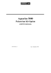
GPS antenna installation
The antenna should not be installed within the reach of any
source of radio interference.
The antenna should not be exposed to smoke (whenever
possible). It should be overlooking any superstructure and
clear of any large metal surface.
1
Antenna bracket
Two U-bolts
on horizontal mast
dia. 56 mm max.
on vertical mast
dia. 56 mm max.
Mount dimensions of
antenna bracket
Mount dimensions
for U-bolts
4
70
On flat
surface
62
4
14
44
62
27.7 27.7
48
Phase centre
24 mm
12 mm
DSNP
1-3
1
Basic operating instructions for the 5000 series
Unpacking and installation
Good connections contribute a lot to the quality of signals
received and therefore to the performance of the receiver.
See that contacts are clean and connectors securely
tightened. Coaxial connectors should be watertight.
In any case, clearance from superstructures and other
antennas is essential.
Whenever possible, the coaxial cable should not be routed
along any cable carrying heavy currents : starters, alternators,
connections to echo sounder, radar, etc.
The antenna downlead should be attached to the mast (using
adhesive or clamps) to preclude any stress on the
connectors.
If you are installing a GPS antenna for a reference station
(see DGNSS Data Link option, section 3), Remember that the
GPS antenna location should be known with the best
accuracy as the accuracy on the DGNSS processing will rely
on it.
Receiver installation
The receiver is designed to withstand a marine environment
(waterproof case), resist dripping water and operate from –
20° to +55°C. Subject to these conditions, the receiver does
not require any special precaution.
However, it is advisable to install the receiver clear of any
moving device and away from splashes of lubricant or water.
Also, direct exposure to excessive heat should be avoided.
The status display screen should be kept away from direct
sun light for better legibility.
1-4
DSNP
Basic operating instructions for the 5000 series
Unpacking and installation
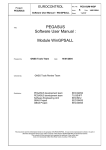
The receiver should be secured from below the case using
the four tapped holes (see dimensions below, receiver case
shown upside down). Use M4 screws and choose a length for
these screws compatible with the 6-mm max. insertion length
allowed in these holes.
1
196 mm
130 mm
56 mm
235 mm
Bottom Side
130 mm
Rear Panel
260 mm
DSNP
1-5
1
Basic operating instructions for the 5000 series
Unpacking and installation
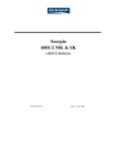
Connections
GPS antenna
DC power source
(a battery or other)
To your navigation
terminal
Power cable,
connected to either POWER input
GPS coaxial cable
RS232 cable
Receiver Rear Panel
1-6
DSNP
Basic operating instructions for the 5000 series
Receiver description
Receiver description
Front Panel
Your receiver is fitted with the following parts on its front and
rear panels.
1
• Front panel controls
ON/OFF pushbutton : used to turn on and off the receiver.
The indicator light nested in this button
starts blinking when you press the
button (if the receiver is connected to
a power source). From the end of the
self-tests, the light is permanently ON.
Scroll pushbutton : used to access the different data
screens available from the status
display.
Activates the screen light for 30
seconds whenever depressed.
A long press on the Scroll pushbutton
allows you to return to screen No. 0.
The indicator light nested in the button
provides information about the
possible planned sessions or session
in progress as soon as you connect
the receiver to the power source:
Blinking : A session is programmed to be run at
a later time & date.
DSNP
1-7
1
Basic operating instructions for the 5000 series
Receiver description
A few minutes before starting the
session, the receiver will be
automatically turned on, unless
meanwhile this is made manually by
the operator (who presses the
ON/OFF button) or unless the power
supply control mode has been set to
"MPW" (refer to page 1-46, Screen
No. 5: Information about sessions for
more information about this
parameter).
ON : An operating or recording session is in
progress. The other indicator light is
necessarily ON.
OFF : No pending session. The receiver will
be powered only manually by using
the ON/OFF button.
Status Display : 2-line×16-character display providing
information about receiver operation
(for a complete description of the
displayed data, see page 1-39,
Checking receiver operation from the
Status Display)
Status Display
ON/OFF
pushbutton
& light indicator
PCMCIA
card reader
Scroll pushbutton
& light indicator
1-8
DSNP
Basic operating instructions for the 5000 series
Receiver description
• PCMCIA card reader
A PCMCIA card reader is located in the left-hand part of the
front panel.
In the basic version, this device is a card reader only. With
optional software, it can be used as a recorder too.
1
The PCMCIA reader is seen from the DSNP GNSS engine as
a conventional I/O port (port P). See page 1-34.
Rear panel
The rear panel is fitted with the following connectors:
- A GPS coaxial connector (GPS antenna input), TNCfemale type
- A DGPS coaxial connector (for optional DGNSS UHF
data link), TNC-female type
- Two RS232 connectors (port A named
"COMPUTER"; port B named "I/O")
- An RS422 connector (port D named "DGPS"), 15-C
SubD-female type, used to connect the optional plugin UHF transmitter (available from DSNP)
- Two POWER connectors in parallel. This allows the
receiver to be maintained in operation while you
swap the power source. For example, in the case of
a battery-powered receiver, you can connect the new
battery before removing the low one.
- With the extended I/O option, four other connectors
are present on the rear panel (see Extended I/O
option in page 4-1).
DSNP
1-9
1
Basic operating instructions for the 5000 series
Getting your equipment started
Getting your equipment started
Basic connections
See precedent chapter, page 1-2, Unpacking and installation.
These connections are briefly reviewed below:
- Use the power cable supplied to connect either of the
two power inputs (or both) to the DC source. Make
sure the DC voltage delivered is within the allowed
range (10 to 15 V for a station, 10 to 36 V for a
mobile) and the source can deliver the required
power.
Mind the polarity of the source (the power input is
protected from polarity reversal by a fuse).
- Use the TNC-TNC GPS coaxial cable supplied to
connect the GPS input to the GPS antenna.
- If your receiver is fitted with an optional built-in UHF
receiver, use the TNC-TNC UHF coaxial cable
supplied to connect the DGPS input to the UHF
antenna (see section 3, DGNSS Data Link, for more
information about that particular point).
- Use a serial cable to connect port A (COMPUTER) or
port B (I/O) to your usual navigation terminal.
PC connection
- Your receiver has been configured earlier to fulfill the
specific function required by your application. This
operation was performed using the DSet Pack or
Conf Pack software.
1-10
DSNP
Basic operating instructions for the 5000 series
Getting your equipment started
- If you encounter one of the problems described later
when getting the receiver started (see page 1-13)
you will have to use the Win Comm tool from the
DSet Pack software.
1
- To use this tool, you will need to run DSet Pack from
a control computer attached to the receiver (see
diagram below).
DSet Pack
Control
computer
Receiver
PC
serial
port
RS232 cable
RS232 line,
Port A,
COMPUTER
(See Appendix G to know how to install and use DSet
Pack).
Getting started
After making the necessary connections (see page 1-10,
Basic connections), just press the ON/OFF pushbutton to get
the receiver started.
What your receiver is then busy to is reported on the status
display.
Follow the instructions below, based essentially on the
observation and use of the status display, to be certain that
your receiver reaches its operational status (for a complete
description of that display, see page 1-39, Checking receiver
operation from the Status Display).
DSNP
1-11
1
Basic operating instructions for the 5000 series
Getting your equipment started
- When you press the ON/OFF button, a welcome
message is displayed until the receiver completes all
its self-tests (this may take a few seconds).
- Then a new display appears gathering the essential
information you need at that time (Screen No. 0).
Example of screen No. 0:
(3)
"0"
for
"screen No. 0"
(2)
(5)
(6)
0 S V 0 8 / 0 9 T D * * / * * s
GP S
1 2 . 2 V
F 1 2 %
(4)
(1)
(7)
- Check the power voltage (1), which should be within
the expected voltage range (otherwise change the
source or adjust it or, if the battery used is low,
replace it).
Power voltage range:
10 to 36 V dc, floating : all the 5000 series, except for
the 500x SD or 500x SK
station
or 10 to 15 V dc : 500x SD or 500x SK station.
- Check that both the count of received satellites (2),
and the count of satellites used (3), increase with
time. The count of received satellites should finally
reflect the currently visible satellite constellation from
the considered point.
1-12
DSNP
Basic operating instructions for the 5000 series
Getting your equipment started
- When the count of satellites used reaches 4, check
that a position solution is available, denoted by the
parameter (4) changing from "HOLD" to a mode tied
to the configuration of your receiver.
1
For example, in the case of a "straight" or "natural"
GPS receiver, this parameter will change from
"HOLD" to "GPS". If DGPS corrections are received,
the parameter will change to "DGPS". All the
possible values of this parameter are listed in page
1-41, Screen No.0: Operating Status).
If corrections are processed in the receiver, you will
probably be interested in knowing the values of the
parameters annotated (5) and (6) in our screen
example above (respectively count of corrections,
received or transmitted, and age of corrections).
If you do not remember the options installed in your
receiver, press the Scroll pushbutton repeatedly until
you reach screen No. 8. After reading this screen,
depress this button again (and keep it depressed for
a longer time) to come back to screen No. 0.
- Now that a solution is available, go to screen No. 2
by pressing the Scroll pushbutton. Check that the
displayed position is the expected one.
- Press the Scroll pushbutton once more to access
screen No. 3. Check that the local time displayed
(beginning of lower line) is correct.
If you have reached this operational stage without any
problem, then you can now let the receiver operate on its
own, even forget it, and proceed with your work.
If you encounter a problem, please read what follows.
DSNP
1-13
1
Basic operating instructions for the 5000 series
Getting your equipment started
A common problem which may be encountered when first
starting up the equipment is the incapability for the receiver to
fix the position whereas the count of satellites used is
sufficient to perform this operation (a minimum of 4 satellites
is required).
This state is reported on Screen No. 0, where "HOLD" keeps
on being displayed while the count of satellites has been 4 or
more for a certain time.
To solve this problem:
- first check the estimated position on Screen No.2
and the local time on Screen No. 3.
- If either of these parameters (or both) are incorrect,
you will need to make the necessary corrections (see
Editing the estimated position, page 1-15 or/and
Editing the receiver time & date, page 1-16).
These corrections require the connection of the
control computer to the A port, as described earlier
(see page 1-10, PC connection) and the use of Win
Comm from DSet Pack running on this computer (see
Appendix G to know how to send commands from
Win Comm).
- If the two parameters are correct, or if you are facing
any other kind of problem, please refer to page 1-55,
Troubleshooting).
1-14
DSNP
Basic operating instructions for the 5000 series
Getting your equipment started
Editing the estimated position
You may need to use this command if the receiver cannot
start functioning because of a too distant estimated position
(> 200 km).
1
The current estimated position (which then becomes the
position solution when the receiver reaches operational
status) is visible on the status display, on Screen No. 2.
- From the control computer, send the following
command to read the coordinates of the estimated
position:
$ECGPQ,GLL<cr><lf>
The receiver will return a reply of this type:
$GPGLL,4716.091395,N,00129.463318,W,180449.00,A*14
- To change the estimated coordinates of your current
position (for example, they should be lat: 39°40.00' N
and long: 4°15.00' E), send the following command:
$ECGLL,3940,N,00415,E<cr><lf>
Changing the coordinates of the estimated position will reinitialize the position processing. If the new coordinates are
correct, the receiver will reach operational status in no time.
A detailed description of the commands used above is
provided in Appendix C.
After entering an estimated position, select screen No. 2 to
check the new coordinates of this position. For example,
screen No. 2 would look like this after sending the $ECGLL
command above :
2 WG S 8 4
H+
4 6
DSNP
3 9 § 4 0 . 0 N
4 § 1 5 . 0 E
1-15
1
Basic operating instructions for the 5000 series
Getting your equipment started
Editing the receiver time & date
You may need to use this command if the receiver cannot
start functioning because of a too different local time
compared with the receiver time.
The current local time is visible on the status display, on
Screen No. 3.
- From the control computer, send the following
command to read the local date & time:
$ECGPQ,ZDA<cr><lf>
The receiver will return a reply of this type:
$GPZDA,180919.00,17,2,1998,+00,00*78
- To change the local time (for example, it should be
08hr 21min, dec18 1997, offset: -1hr), send the
following command:
$ECZDA,082100,18,12,1997,-1,00<cr><lf>
Changing the local time will re-initialize the position
processing. If the local time is now correct, the receiver will
reach operational status in no time.
A detailed description of the commands used above is
provided in Appendix C.
After entering a local time, select screen No. 3 to check your
entry. For example, screen No. 3 would look like this after
sending the $ECZDA command above :
3 Os c - 1 . 0 0 E + 0 0 s / s
0 8 : 2 1 : 0 0 = Z - 0 1 : 0 0
1-16
DSNP
Basic operating instructions for the 5000 series
Getting your equipment started
Checking the fix mode used
Screen No. 0 shows the fix mode in which the receiver
operates (see parameter (4) in the display example of page 111). If for any reason, you need to change that mode, use the
FIXMOD command as explained below:
1
- From the control computer, send the following
command to read the fix mode currently used:
$PDAS,FIXMOD<cr><lf>
If the receiver is operating in the "straight" GPS
mode, the reply will be:
$PDAS,FIXMOD,3,1*39
- To change that mode (for example, you want to work
in single-station DGPS with reference station No.
801), send the following command:
$PDAS,FIXMOD,4,1,801<cr><lf>
- Check the new fix mode used by sending the
following command:
$PDAS,FIXMOD<cr><lf>
The receiver should return:
$PDAS,FIXMOD,4,1,801*2B
Changing the
processing.
fix
mode
will
re-initialize
the
position
A detailed description of the command used above is
provided in Appendix C.
DSNP
1-17
1
Basic operating instructions for the 5000 series
Getting your equipment started
Checking the type of position solution used for
navigation
The type of position solution on which to base your navigation
should be distinguished from the fix mode used.
In a kinematic fix mode for example (KART or LRK), three
different types of position solutions are available for your
navigation: EDGPS, KART A/LRK A (A for "Accurate 1-Hz
rate") or KART R/LRK R (R for "Real-time 10-Hz rate"). In
these cases of use, you will have to specify the desired type
of position solution otherwise the receiver will deliver the
default position type, which is "straight" GPS, or conventional
DGPS (if available).
If you need to change the type of position solution used for
navigation, use the NAVSEL command as explained below.
- From the control computer, send the following
command to read the type of position solution used
for navigation:
$PDAS,NAVSEL<cr><lf>
If the receiver is operating in the "straight" GPS or
conventional DGPS mode, the reply will be:
$PDAS,NAVSEL,1,1*29
- To change that selection (for example, you want to
select the KART A/LRK A fix), send the following
command:
$PDAS,NAVSEL,3,1<cr><lf>
- Check the new selection by sending the following
command:
$PDAS,NAVSEL<cr><lf>
1-18
DSNP
Basic operating instructions for the 5000 series
Work sessions
The receiver should return:
$PDAS,NAVSEL,3,1*2B
A detailed description of the command used above is
provided in Appendix C.
1
Work sessions
Theory of operation
Work sessions constitute a fundamental operating aspect of
your receiver. You need to know everything about sessions if
you do not want, in some particular cases, to be surprised by
the behavior of the receiver.
A work session is defined as a period of time during which
you want a receiver to operate. The rest of the time, power
will be removed from the receiver (only the session-managing
circuit will remain powered).
There are two good reasons for you to use the concept of
session:
- you want to limit the daily operating time of the
receiver to save battery power (at a station for
example).
- If you use the PCMCIA recording capability, you want
to precisely define the recording time spans for best
management of the PCMCIA memory space.
Indeed, if the PCMCIA recording capability option is
installed, defining a programmed session with
recording bit =1, or an immediate session, and
programming a data output (or data outputs) on port
P will result in the recording of the data on the
PCMCIA card during the whole session.
DSNP
1-19
1
Basic operating instructions for the 5000 series
Work sessions
Whatever the use you make of sessions, you have to decide
on the value to give to the option controlling the receiver
power supply. Two values are possible for that option (see
also the $PDAS,EXPSES command):
- Either you give full control of the power supply to the
session-managing circuit (choose "AUTPW").
Warning! Providing a user with a receiver configured
with this option active and no pending session may
get this user into trouble if no further explanation is
provided. Indeed, the receiver will unconditionally
switch off after 30 seconds of operation if nothing
else is done in the meantime!
- or you still allow an operator to turn on and off the
receiver outside the session times (choose
"MANPW"). Programmed sessions however, if any,
will continue to have priority in the management of
the power supply. If there is no programmed session
and this option is used, the receiver will operate on a
permanent basis, with power only controlled by the
ON/OFF pushbutton.
There are two kinds of sessions:
- programmed session
- immediate session
1-20
DSNP
Basic operating instructions for the 5000 series
Work sessions
• Programmed session
1
A programmed session is defined by:
- a start time
- an end time
- a recording indicator (0: without recording; 1: with
recording)
- a session label (8 characters max.)
Unless the desired programmed sessions are present in the
receiver configuration —in which case you have nothing else
to do but use these sessions— you can still define, re-define
or delete a programmed session using the $PDAS,SESSN
and $PDAS,DELSES commands.
Programmed sessions can be run once (ON) or several times
(CYCLE) if you give the receiver enough time to do so.
• Immediate session
An immediate session starts when the appropriate
$PDAS,EXPSES command ($PDAS,EXPSES,IMMED) is run
in the receiver:
- If the command is in the receiver configuration, the
immediate session will start when you depress the
ON/OFF pushbutton.
- If you send this command from the control computer,
the immediate session will start when the command
is processed in the receiver.
There is a single way of ending an immediate session:
- by sending the $PDAS,EXPSES,END command.
DSNP
1-21
1
Basic operating instructions for the 5000 series
Work sessions
• Recovering permanent operation
Permanent operation of the receiver is obtained by rejecting
all the programmed sessions, if any, or by programming a
single session from 0hr 00 to 24hr 00.
A few programming examples
- The session type and power supply control
parameters are grouped in the $PDAS,EXPSES
command.
- All the parameters defining a programmed session
are grouped in the $PDAS,SESSN command.
- Programmed sessions can be deleted using the
$PDAS,DELSES command
For more information about these commands, see Appendix
C.
• Listing and validating programmed sessions
- From the control computer, send the following
command:
$PDAS,SESSN<cr><lf>
Receiver reply (example):
$PDAS,SESSN,1,111500,140000,0,*5E
$PDAS,SESSN,2,154500,173000,0,*5C
Interpreting the receiver reply:
1st line: session 1, from 11hr15 to
14hr00, without data recording.
2nd line: session 2, from 15hr45 to
17hr30, without data recording.
1-22
DSNP
Basic operating instructions for the 5000 series
Work sessions
- From the control computer, send the following
command to validate these sessions (run order: 2
then 1 for example, sessions repeated) and to select
automatic power supply control:
1
$PDAS,EXPSES,CYCLE,AUTPW,2,1<cr><lf>
- Check the changes made by sending the following
command:
$PDAS,EXPSES<cr><lf>
Expected receiver reply :
$PDAS,EXPSES,CYCLE,AUTPW,2,1*36
• Running/ending an immediate session with data
recording on PCMCIA
(requires PCMCIA recording capability option).
- For example, from the control computer, define a
GPS pseudo-range output...:
$PDAS,PRANGE,1,P,1,10,4<cr><lf>
Check the definition of this output by sending the
following command:
$PDAS,PRANGE<cr><lf>
$PDAS,PRANGE,1,P,1,10,4,0,0,0*70
$PDAS,PRANGE,2,N*59
- ...and define a raw data output:
$PDAS,GPSDAT,1,P,3,3,3,3<cr><lf>
DSNP
1-23
1
Basic operating instructions for the 5000 series
Work sessions
Check the definition of this output by sending the
following command:
$PDAS,GPSDAT<cr><lf>
$PDAS,GPSDAT,1,P,3,3,3,3*5E
$PDAS,GPSDAT,2,N*43
- From the control computer, send the following
command to start the immediate session:
$PDAS,EXPSES,IMMED<cr><lf>
Check that a session is now in progress by sending
the following command:
$PDAS,EXPSES<cr><lf>
$PDAS,EXPSES,IMMED,MANPW*2F
- To end the immediate session, send the following
command:
$PDAS,EXPSES,END<cr><lf>
Check that there is no more session in progress by
sending the following command:
$PDAS,EXPSES<cr><lf>
$PDAS,EXPSES,END,MANPW*28
1-24
DSNP
Basic operating instructions for the 5000 series
Work sessions
• Selecting Manual control for the power supply and
disabling all programmed sessions
1
- From the control computer, send the following:
$PDAS,EXPSES,END,MANPW<cr><lf>
(No receiver reply)
Information about sessions is reported on the receiver status
display by selecting screen No. 5. Display example:
5 S E S : I MME
MPW R E C
DSNP
B
E
8 : 1 8
8 : 2 4
1-25
1
Basic operating instructions for the 5000 series
Usual changes made to the receiver configuration from the Control computer
Usual changes made to the receiver
configuration from the Control computer
While using your receiver, you will probably need to make
some changes to the receiver configuration, more particularly
regarding its data outputs.
This chapter discusses the usual changes you can make from
the control computer (see page 1-10, PC connection).
Other changes can be made (see Appendix C in which all the
possible commands are presented).
Enabling/disabling all data outputs
You may be interested in disabling all the active data outputs
(raw-data and computed-data outputs), for example in order
to facilitate maintenance steps on the attached peripheral
equipment. This is simply achieved through a single
command:
- From the control computer, send the following
command:
$PDAS,OUTOFF<cr><lf>
(No receiver reply)
- The inverse operation is also very simple. Just send
the following command to re-enable all the data
outputs:
$PDAS,OUTON<cr><lf>
(No receiver reply).
1-26
DSNP
Basic operating instructions for the 5000 series
Usual changes made to the receiver configuration from the Control computer
The syntax of the above commands is detailed in
Appendix C.
1
Editing the settings of a serial port
You may want to change the settings of a serial port on the
receiver in order to allow communications with your peripheral
equipment.
- From the control computer, send the following
command to list the settings of all the receiver serial
ports:
$PDAS,HARDRS<cr><lf>
The receiver will return a reply of this type:
$PDAS,HARDRS,4,1,A,9600,8,1.0,N*0A
$PDAS,HARDRS,4,2,B,9600,8,1.0,N*0A
$PDAS,HARDRS,4,3,C,9600,8,2.0,N*09
$PDAS,HARDRS,4,4,D,19200,8,1.0,N*3F
- For example, to change the settings of port B to
19200 Bd, 7 data bits, Odd parity, send this
command:
$PDAS,HARDRS,,,B,19200,7,1,O<cr><lf>
Check the new settings for port B by sending the
following command:
$PDAS,HARDRS<cr><lf>
$PDAS,HARDRS,4,1,A,9600,8,1.0,N*0A
$PDAS,HARDRS,4,2,B,19200,7,1.0,O*31
$PDAS,HARDRS,4,3,C,9600,8,2.0,N*09
$PDAS,HARDRS,4,4,D,19200,8,1.0,N*3F
DSNP
1-27
1
Basic operating instructions for the 5000 series
Usual changes made to the receiver configuration from the Control computer
- If you change the settings of the serial port on the
receiver, do not forget to make the same changes on
the concerned serial port of the control computer !!
Refer to Appendix C for more information on the
$PDAS,HARDRS command.
Editing/adding the definition of a computed data
output
The definition of each of the computed-data outputs
generated according to the receiver configuration can be
modified through the following steps:
- From the control computer, send the following
command to list all the data outputs:
$PDAS,OUTMES<cr><lf>
The receiver will return a reply of this type:
$PDAS,OUTMES,1,A,-1,10,1,5,7,8,9,10,20*4F
$PDAS,OUTMES,2,A,-1,10,2,7,8,5,11,20*5B
$PDAS,OUTMES,3,A,-1,10,12,20*51
$PDAS,OUTMES,4,A,-1,10,13,20*57
$PDAS,OUTMES,5,A,-1,10,3,5,6,20*64
...
1-28
DSNP
Basic operating instructions for the 5000 series
Usual changes made to the receiver configuration from the Control computer
- For example, to enable output #2 on port B in 1pps
mode, type the following command:
$PDAS,OUTMES,2,B,4<cr><lf>
- Check the changes made to output 2:
1
$PDAS,OUTMES,2<cr><lf>
$PDAS,OUTMES,2,B,4,10,2,7,8,5,11,20*70
- To disable an output (output #2 for example), send
one of the following commands:
$PDAS,OUTMES,2,B,0<cr><lf>
(but you lose the initial trigger information relevant to
this output by using "0" as the 3rd parameter in the
command)
or
$PDAS,OUTMES,2,B,-4,<cr><lf>
(you preserve the initial trigger information by placing
"-" before the 3rd parameter in the command)
Refer to Appendix C for more information on the
$PDAS,OUTMES command.
DSNP
1-29
1
Basic operating instructions for the 5000 series
Usual changes made to the receiver configuration from the Control computer
Editing the definition of a GPS raw data output
The definition of each of the raw-data outputs generated
according to the receiver configuration can be modified
through the following steps:
- From the control computer, send the following
command to list all the generated data outputs:
$PDAS,GPSDAT<cr><lf>
The receiver will return a reply of this type:
$PDAS,GPSDAT,1,B,-3,-3,-3,-3*4C
$PDAS,GPSDAT,2,N*43
- For example, to change the definition of output #1
(described in the1st reply line), send a command of
this type:
$PDAS,GPSDAT,1,A,3,3,3,3<cr><lf>
Check the changes made:
$PDAS,GPSDAT<cr><lf>
$PDAS,GPSDAT,1,A,3,3,3,3*4F
$PDAS,GPSDAT,2,N*43
Refer to Appendix C for more information on the
$PDAS,GPSDAT command.
1-30
DSNP
Basic operating instructions for the 5000 series
Usual changes made to the receiver configuration from the Control computer
Editing the definition of a pseudorange-data
output
The definition of each of the pseudorange-data outputs
generated according to the receiver configuration can be
modified through the following steps:
1
- From the control computer, send the following
command to list all the generated data outputs:
$PDAS,PRANGE<cr><lf>
The receiver will return a reply of this type:
$PDAS,PRANGE,1,B,-1,10,4,0,0,0*4F
$PDAS,PRANGE,2,N*59
- For example, to change the definition of output #1
(described in the1st reply line), send a command of
this type:
$PDAS,PRANGE,1,A,1<cr><lf>
Check the changes made:
$PDAS,PRANGE<cr><lf>
$PDAS,PRANGE,1,A,1,10,4,0,0,0*61
$PDAS,PRANGE,2,N*59
Refer to Appendix C for more information on the
$PDAS,PRANGE command.
DSNP
1-31
1
Basic operating instructions for the 5000 series
Usual changes made to the receiver configuration from the Control computer
Editing the navigation mode currently selected
You may want to change the navigation mode due to new or
unexpected navigation conditions:
- From the control computer, send the following
command to check the currently selected navigation
mode:
$PDAS,NAVSEL<cr><lf>
The receiver will return a reply of this type:
$PDAS,NAVSEL,1,1*29
(DGPS solution (1), Position mode (1))
- For example, to select the EDGPS solution to be
used in navigation, send this command:
$PDAS,NAVSEL,2<cr><lf>
Check the changes made:
$PDAS,NAVSEL<cr><lf>
$PDAS,NAVSEL,2,1*2A
Refer to Appendix C for more information on the
$PDAS,NAVSEL command.
1-32
DSNP
Basic operating instructions for the 5000 series
Usual changes made to the receiver configuration from the Control computer
Editing the filtering time constant applied to speed
You may want to change the filtering time constant applied to
the speed parameter, due to new or unexpected navigation
conditions:
1
- From the control computer, send the following
command to check the currently selected filtering
time constant:
$PDAS,FILTER<cr><lf>
The receiver will return a reply of this type:
$PDAS,FILTER,6*30
(speed filtering time constant: 6 seconds)
- To change the speed filtering time constant to 32
seconds for example, send this command:
$PDAS,FILTER,32<cr><lf>
Check the changes made:
$PDAS,FILTER<cr><lf>
$PDAS,FILTER,32*07
Refer to Appendix C for more information on the
syntax of the $PDAS,FILTER command.
DSNP
1-33
1
Basic operating instructions for the 5000 series
PCMCIA reader
PCMCIA reader
Inserting a PCMCIA card
- Unlock the cover by applying a finger on its uppermiddle part and then by pushing it. The cover will
open when you remove your finger.
- Orient the PCMCIA card as shown below.
- Insert the PCMCIA in the slot and push gently until
you hear a click (indicating that the card is locked in
the reader).
Arrow on PCMCIA
- Close the cover (a click indicates that the cover is
locked) by pushing the cover, in the same way as you
did previously to open it.
1-34
DSNP
Basic operating instructions for the 5000 series
PCMCIA reader
Removing a PCMCIA card
1
- Unlock the cover.
- With a finger, depress the black, square-shaped,
knob located to the right of the reader until the card
is released.
- Take the card out of the reader.
PCMCIA file organization
- All the files are stored in the PCMCIA root directory.
No subdirectories can be created on a PCMCIA card.
PCMCIA control
- You need a computer attached to the receiver's port
A to perform the usual operations described in the
continuation of this chapter. Use DSet Pack or Win
Comm to send the required commands.
DSNP
1-35
1
Basic operating instructions for the 5000 series
PCMCIA reader
- If your receiver is fitted with the PCMCIA recording
capability option, see Work sessions, page 1-19, to
know how to write on the PCMCIA.
Reading the amount of free memory
- From the control computer, send the following
command:
$PDAS,MEMORY<cr><lf>
- The receiver will return a reply of this type:
$PDAS,MEMORY,DIR,1,1,,122880,3858432,0
The percentage of free memory on the PCMCIA card
is indicated in Screen No. 0 on the status display.
Display example:
0 S V 0 9 / 1 2 T D 1 1 / 0 1 s
EDG P *
1 2 . 1 V
F 4 5 %
Free memory percentage
1-36
DSNP
Basic operating instructions for the 5000 series
PCMCIA reader
Listing all the files present on a card
1
- From the control computer, send the following
command:
$PDAS,MEMORY,DIR<cr><lf>
- The receiver will return a reply of this type:
$PDAS,MEMORY,DIR,3,1,,122880,3858432,2
$PDAS,MEMORY,DIR,3,2,sesimmed.d00,694
44,18,02,1998,092034.0
$PDAS,MEMORY,DIR,3,3,sesimmed.d01,303
04,18,02,1998,092230.0
DSNP
1-37
1
Basic operating instructions for the 5000 series
PCMCIA reader
Loading a configuration from a card
For successful completion of this load operation, a
configuration file named "CONFIG.CFG" should be stored on
the PCMCIA card. Typically, this type of file is created using
the DSNP ConfPack Software.
The configuration file currently used by the receiver can be
identified using the $PDAS,COMMNT command.
Typical procedure:
- From the control computer, send this series of
commands:
$PDAS,COMMNT<cr><lf>
(for identification of the default configuration)
$PDAS,COMMNT,2,1,AQUARIUS
5000 SERIES*14
$PDAS,COMMNT,2,2,DEFAULT
CONFIGURATION*2B
$PDAS,CONFIG,LOAD<cr><lf>
$PDAS,COMMNT<cr><lf>
(for identification of the configuration
you've just loaded)
$PDAS,COMMNT,1,1,CONFIG PALMTOP*61
1-38
DSNP
Basic operating instructions for the 5000 series
Checking receiver operation from the Status Display
Checking receiver operation from the
Status Display
Your receiver is fitted with a 2-line × 16-character display
which allows you to check its current operating status. A
Scroll pushbutton on the front panel allows you to access the
different data available from this display.
1
When you turn on the receiver, the following message
appears on the status display until the self-tests are complete:
DA S S AU L T
S E R C E L
* GN S S
R E C E I V E R
*
Then the status display changes as the receiver status
changes. Ten different screens have been designed to
describe the receiver's internal data (status, configuration,
options, software versions). You only need to use the Scroll
pushbutton located on the front panel to access each of these
screens. A long press on this button will unconditionally take
you back to screen No. 0 (the most important one at receiver
start up).
DSNP
1-39
1
Basic operating instructions for the 5000 series
Checking receiver operation from the Status Display
Each screen is identified by a number to help you navigate
through the set of screens. The screen number is located at
the beginning of the upper line:
Screen number (0-9)
When the amount of data is too large to fit on a single screen,
several "sub-screens" are created for this screen. In this
case, the screen number is recalled at the beginning of each
sub-screen. Use the same button (the Scroll pushbutton) to
access the different sub-screens (and then to access the next
screen).
1-40
DSNP
Basic operating instructions for the 5000 series
Checking receiver operation from the Status Display
Screen No.0: Operating Status
At the end of the self-tests, status screen No. 0 appears.
Display example:
Count of
corrections,
received or transmitted
Count of SVs,
used / received
Fix mode:
EDGP
IKAR
KART
ILRK
LRK
GPS
REF
HOLD
DGPS
MDGP*
WDGP
GNOS
0 S V 0 8 / 1 2 T D 1 1 / 0 1 s
EDG P * # 1 2 . 2 V
F 1 2 %
Battery voltage
(in V)
1
Age
of
corrections
(99 s max.)
Free memory space
on PCMCIA (in %)
In GPS or GNOS fix mode only, appears if
WAAS/EGNOS integrity data is used for SV monitoring
Indicates current operation in Average position mode (the
receiver is used at a reference station).
• Fix mode
EDGP (EDGPS)
IKAR
KART
ILRK
LRK
GPS
REF
:
:
:
:
:
:
:
HOLD
DGPS
MDGP (MDGPS)
WDGP
:
:
:
:
GNOS :
DSNP
Enhanced DGPS
Kinematic Application Initialization
Kinematic Application Real Time
Long-Range Kinematic Initialization
Long-Range Kinematic
"pure" or "straight" GPS
User-set reference position (for a station
only) (not a computed position)
No position solution available
Differential GPS
Multi-differential GPS (*: future use)
Differential GPS using WADGPS corrections
and integrity control from GEO, and possibly
WAAS/EGNOS pseudoranges
Same as GPS except that WAAS/EGNOS
pseudoranges are involved in the position
processing.
1-41
1
Basic operating instructions for the 5000 series
Checking receiver operation from the Status Display
Screen No. 0 (refresh rate: 1.0 second) will be maintained on
the status display until you depress the Scroll button.
If an error is detected in the receiver (anomaly, etc.), the
screen number will start blinking, prompting you to have a
look at screen No.1 to know more about the detected error(s).
Unless the detected error still persists, it is simply
acknowledged when quitting the screen reporting that error.
With screen No. 0 currently displayed, depressing the Scroll
pushbutton repeatedly will cause new screens to appear in
the order given below.
Screen No. 1: Error report
Depending on the number of errors detected (none, one or
more), several sub-screens for screen No. 1 may exist.
Display example:
Error
identification
Error
number
1 P O S I T
0 6 0
3 0
1 3 : 4 4
/
Day of
occurrence
(1 - 31)
Error start
time
(hh:mm)
Error
extra-code
0 0 0 1 2
1 3 : 5 0
Error end time
(hh:mm) or current
time if error still
persists
The list of all the possible errors is given in the
Troubleshooting chapter, page 1-55.
1-42
DSNP
Basic operating instructions for the 5000 series
Checking receiver operation from the Status Display
Screen No. 2: Position solution
Depending on the coordinate system used (with or without
projection), this screen can be of two different types:
Without projection (example):
Reference Datum
used
2 WG S 8 4
H
+ 4 8
Altitude
1
Latitude
4 7 § 1 6 . 1 N
1 § 2 9 . 4 W
Longitude
With projection (example):
Projection
used
2 L a mb 2
H
+ 4 8
Altitude
Northing
+ 2 5 9 1 2 7 N
+ 3 1 0 5 0 0 E
Easting
If no solution is available ("HOLD" displayed on screen No.0),
this screen will display the "initial position", as defined by the
configuration, or the latest position computed in case of
lasting solution unavailability, due to reception loss for
example.
The position displayed is not for navigation purposes. As it is
only a coarse indication of the current position, it does not
reflect the real degree of accuracy achieved by the position
solution.
DSNP
1-43
1
Basic operating instructions for the 5000 series
Checking receiver operation from the Status Display
Screen No. 3: Time information
Display example:
Main oscillator drift speed
3 Os c - 1 . 1 2 E - 0 8 s / s
1 4 : 2 4 : 1 8 = Z + 0 2 : 3 0
Local time
1-44
= UTC (Zoulou) + ∆ time
DSNP
Basic operating instructions for the 5000 series
Checking receiver operation from the Status Display
Screen No. 4: GNSS reception status
Each line describes the reception of a satellite. Hence, two
satellites are shown on a sub-screen and n sub-screens will
exist if 2n (or 2n-1) satellites are received. In WADGPS
mode, the selected GEO appears in the lower line of the last
sub-screen No. 4.
1
Display example with GPS SV PRN 18 and GEO PRN 138:
GPS SV state:
r: received but not used
d : received but user-deselected
u: received and used
b: received but deselected by
WAAS/EGNOS integrity control
GPS SV
PRN
GPS SV orbit:
∧ : ascending
∨ : descending
S/N ratio
(dB)
Elevation Azimuth
(°)
(°)
4
1 8 u ~ 4 3 ^ 8 9 / 1 2 0
S V 13 8 r ~ 4 0 = 1 0 / 0 4 3
Denotes a GEO
GEO PRN
(≥ 120)
GEO state:
r: received but not used
u: received and used
In the lower line containing the description of a GEO, the
elevation and azimuth will be reported as equal to “000” if no
ephemeris data is available to compute these angles.
DSNP
1-45
1
Basic operating instructions for the 5000 series
Checking receiver operation from the Status Display
Screen No. 5: Information about sessions
The current or pending session is described on the screen.
Display example:
Session
status
(see below)
5 S E S
A PW
Power supply mode:
"APW": Automatic
"MPW": Manual
I MME
R E C
Recording status:
"REC": recording in
progress
"blank": no recording
in progress
Begin time
(hh:mm) of next or
current session
B 2 0 : 1 0
E 2 2 : 1 2
End time (hh:mm) of
next or current
session,
or current time if
Immediate session
Power supply mode:
APW : If this option is active, sessions control the
power supply of the receiver. The ON/OFF
pushbutton is still usable but it won't turn off
the receiver if a session is in progress.
MPW : If this option is active, sessions have no
control on the power supply of the receiver.
Only the ON/OFF pushbutton has.
Session status:
ON : Programmed sessions are run once
CYCL : Programmed sessions will be repeated, if this
may happen
IMME : Immediate recording session in progress.
Data recorded on PCMCIA (if option installed)
END : All sessions are disabled, or ends the
immediate session.
1-46
DSNP
Basic operating instructions for the 5000 series
Checking receiver operation from the Status Display
Screen No. 6: Information about corrections
1
• If the equipment is connected to a transmitting
beacon:
Display example:
Frequency band:
U: UHF band
M: MF band *
H: HF band *
X: undefined
Beacon Id.
Format type:
DSNP
RTCM
LRK
Transmission
baud rate (Bd)
6 U 0 0 1 3
D S N P 4 8 0 0 b
C 1 / 3
4 4 6 . 3 6 2 5 MH z
Transmit slot number
/
Number of slots
(in UHF band),
1pps synchronous
mode,
C0/0: free mode
Transmission frequency
(in MHz)
Screen obtained with no programming performed in the UHF
Data Link module:
6 X * * * *
x x x x * * * * b
* * * . * * * * MH z
*: Future use
DSNP
1-47
1
Basic operating instructions for the 5000 series
Checking receiver operation from the Status Display
• if the equipment is a corrections receiver:
Display example:
Transmission
baud rate
(Bd)
Beacon Id
Frequency band:
U: UHF band
M: MF band *
H: HF band *
N: Numeric
X: undefined
6 U 0 0 1 3
4 8 0 0 b
3 2 d B
4 4 6 . 3 6 2 5 MH z
Signal/ Noise
ratio
Receiving frequency
(in MHz)
(*: Future use)
Screen No. 7: Differential corrections
Each line describes the correction to be applied to a
measurement made from the satellite specified in the line.
Hence, two corrections are shown on a sub-screen and n
sub-screens will exist if 2n (or 2n-1) corrections are
computed/received. Display example:
SV number
7
S V
2 3
1 0
SV number
1-48
Pseudorange
Correction value in m
+ 8 4
+ 3 6
Pseudorange
Correction value in m
Correction speed
in m/s
+ 0 . 4
+ 1 . 2
Correction speed
in m/s
DSNP
Basic operating instructions for the 5000 series
Checking receiver operation from the Status Display
Screen No. 8: Firmware Options installed
The first line indicates the serial number of the receiver. Each
of the next lines identifies a firmware option installed in the
receiver. The number of sub-screens for screen No. 8 will
depend on the number of options installed.
1
Display example:
1st screen, 1st line:
Receiver identification
8 C 2
O P 0 1
0 0 1 4 5
DGN S SMOD E
Option number
and identification
OP01 : DGNSSMODE
OP02 : REFSTATION
OP03 : KARTMODE
OP04 : LRKMODE
OP05 : USERGEOID
OP06 : RECORDING
OP07 : QA/QC
DSNP
1-49
1
Basic operating instructions for the 5000 series
Checking receiver operation from the Status Display
Screen No. 9: Hardware and Software
identification
Each subassembly in the receiver is described on a subscreen. Display examples:
Data Link:
9 T D 2 0
E U H F V 1 0 3 0 0
or
9 T D 0 0
R U H F V 1 0 3 0 0
GNSS Engine:
9 CM 0 8
CM 0 8
CMB L V 0 0 1 0 9
CMP Y V 0 0 2 0 4
UC (CPU) board:
9 U C 0 1
U C 0 1
U C B S V 2 0 0 0 0
U C B L V 1 0 0 0 0
9 U C 0 1
U C B N V 2 0 2 0 4
Hardware
identification
1-50
Software
identification
DSNP
Basic operating instructions for the 5000 series
Rear panel Connectors
Rear panel Connectors
1
GPS antenna
DC power source
(a battery or other)
To your navigation
terminal
Power cable,
connected to either POWER input
Diff (DGPS)
antenna input
Fuse (2 A)
DSNP
GPS coaxial cable
RS232 cable
DGPS connector (Port D)
1-51
1
Basic operating instructions for the 5000 series
Rear panel Connectors
COMPUTER connector,
(RS232 Port A),
type: JKX FD1G 07 MSSDSM
(plug: JBX1 MPN), manufacturer: FCI,
pin view
3
2
TXD
output
3
RXD
input
4
REMOTE ON
input
5
GND
6
CTS
output
7
RTS
input
4
I/O connector,
(RS232 Port B),
type: JKX FD1G 07 MSSDSM
(plug: JBX1 MPN), manufacturer: FCI,
pin view
Pin
1
Signal
+12 V
output
2
TXD
output
3
RXD
input
4
Not used
5
GND
6
CTS
output
7
RTS
input
6
1
5
7
3
output
5
7
2
Signal
+12 V
6
1
2
Pin
1
4
POWER connector
type: JKX FD1G 04 MSSDSM
(plug: JBX1 MPN), manufacturer: FCI,
pin view
1
2
1-52
4
3
1
2
4
3
Pin
1
Signal
+ Power input
2
+ Power input
3
- Power input
4
- Power input
DSNP
Basic operating instructions for the 5000 series
Rear panel Connectors
TNC-male
coaxial connector
(to/from optional DGPS
antenna)
TNC-male
coaxial connector
(GNSS antenna input)
GPS
DGPS
DGPS
connector
(RS422 Port D), pin view,
15-C SubD-female type.
For exclusive use by DSNP UHF
transmitter
8
15
DSNP
1
9
Pin
1
Signal
TXD+
output
2
TXD-
output
3
RXD+
input
4
RXD-
input
5
Not used
6
GND
7
GND
8
+12 V
9
Reserved
10
Reserved
11
Reserved
12
Reserved
13
Reserved
14
Reserved
15
Not used
1
output
1-53
1
Basic operating instructions for the 5000 series
Rear panel Connectors
RS232 cable
A
B
605076570
1
6
7
A is a 7-contact JKX FD 1G 07 MSSDSM (5011253) plug with
JBX1 MPN (5080359) sleeve. Manufacturer: FCI.
B is a 9-contact female subD DE-9S (5030357) connector
with metal cover 8655MH09-11 (5080357). Manufacturer:
FCI.
Shielded cable, 4-pair, FMA2R (6030097). Overall length 2 m.
1-54
A plug
B plug
1
9
VIN
2
2
RX
3
3
TX
4
4
ON
5
5
GND
6
7
RTS
7
8
CTS
DSNP
Basic operating instructions for the 5000 series
Troubleshooting
Troubleshooting
Front Panel Indicators
ON/OFF
indicator
OFF
Scroll
indicator
OFF
Meaning
1
Receiver not powered.
If this status is obtained after pressing
the ON/OFF push-button, check
power supply connection (cable,
connectors), power source, power
voltage, rear panel fuse.
DSNP
Flashing
OFF
ON
OFF
ON
Flashing
OFF
Flashing
ON
ON
If this status is obtained after a period
of operation, this means that the
receiver has completed the
programmed sessions and the
receiver is now OFF due to automatic
power supply control.
Self-tests in progress (initialisation
phase)
Operating receiver. No pending
session.
Operating receiver, due to manual
power supply control. Pending
session.
Receiver in standby, due to automatic
power supply control. Pending
session.
Operating receiver. Recording on
PCMCIA in progress.
1-55
1
Basic operating instructions for the 5000 series
Troubleshooting
Error report
Errors are reported in two different ways:
- On the status display, on Screen No.1. Each error
occupies a "sub-screen" (see Screen No. 1: Error
report chapter, page 1-42).
- As a receiver reply to the $PDAS,DEFLT command
(see this command in Appendix C).
Error families
Errors are classified into families, depending on the probable
origin of error. The table below summarizes the 11 different
error families
Family
number
00
1-56
Origin
No errors
Error label
NONE
CM
01
Core Module
02
Application Configuration
CONFG
03
DGPS
DGPS
04
Coordinate system
GEODY
05
Input/Output
I/O
06
User Interface
IHM
07
Power supply/interface
INTRF
08
Navigation
NAVIG
09
Fix processing
POSIT
10
System
SYSTM
11
Data link
TD
DSNP
Basic operating instructions for the 5000 series
Troubleshooting
Error classification
Errors are classified into four categories depending on
gravity:
- Simple information reported to user (code 1)
1
- Warnings (code 2). The receiver operates correctly
but might be disturbed by the reported error.
- Serious errors (code 3). The receiver operates but
delivers erroneous results.
- Fatal errors (code 4). The receiver can no longer
operate correctly. You should re-initialize the
receiver.
DSNP
1-57
1
Basic operating instructions for the 5000 series
Troubleshooting
Error list
No.
Family
Gravity
01
02
03
04
05
1 - CM
1 - CM
1 - CM
1 - CM
1 - CM
4
4
3
3
3
GPS not ready
RAM error
Processor error
Timing error
Program memory error
06
07
1 - CM
1 - CM
3
3
Data memory error
Reception circuit error
08
1 - CM
3
Correlation circuit error
09
1 - CM
4
C/A-P/YCommunication error
10
11
12
13
14
15
16
17
1 - CM
1 - CM
1 - CM
1 - CM
1 - CM
1 - CM
1 - CM
1 - CM
2
2
2
1
1
1
1
3
Non-used output data
Non-identified input data
Non-complying input data
GPS data error
DPRAM error
Erroneous message length
EEPROM error
Trigger time-tag error
18
4
Config integrity altered
3
Config parameter error
3
3
3
No transmitting station
CPU-DIFF overflow
Coordinate system error
23
24
2CONFG
2CONFG
3 - DGPS
3 - DGPS
4GEODY
5 - I/O
5 - I/O
2
2
Unknown remote command
Non-complying param. format
25
26
5 - I/O
5 - I/O
2
3
Non-complying format block
Command checksum error
27
30
5 - I/O
5 - I/O
3
3
DPR1 Input error
Non-complying LRK block
31
32
33
34
5 - I/O
5 - I/O
5 - I/O
5 - I/O
3
3
3
3
Port A Overflow
Port B Overflow
Port C Overflow
Port D Overflow
19
20
21
22
1-58
Meaning
Error label
GPS not ready
RAM anomaly
Processor anomaly
Timing anomaly
Program memory
anomaly
Data memory anomaly
Reception circuit
anomaly
Correlation circuit
anom
Communication C/A P/Y
Unread output datas
Unknown input datas
Bad input datas
GPS data anomaly
DPRAM anomaly
Bad message length
EEPROM anomaly
Datation Trigger
Error
Bad config
integrity
Config parameter
error
No sending dtation
CPU-DIFF overflow
Geodesy error
Unknown telecommand
Bad parameter
format
Bad block format
Bad telecommand
checksum
Input error on DPR1
Bad LRK block on
port D
Overflow PortA
Overflow PortB
Overflow PortC
Overflow PortD
DSNP
Basic operating instructions for the 5000 series
Troubleshooting
35
5 - I/O
2
Format interpretation error
36
37
38
39
40
41
42
43
44
45
46
47
5 - I/O
5 - I/O
5 - I/O
5 - I/O
6 - IHM
7 - INTRF
7 - INTRF
7 - INTRF
7 - INTRF
7 - INTRF
7 - INTRF
7 - INTRF
3
3
3
3
2
4
4
3
3
2
4
3
Port A Input error
Port B Input error
Port C Input error
Port D Input error
User Interface error
Xilinx Load
Low Power Command
PCMCIA overflow
File system full
PC board not recognized
Battery voltage too low
Corrupted file system
48
52
53
54
55
56
57
7 - INTRF
7 - INTRF
7 - INTRF
7 - INTRF
7 - INTRF
8 - NAVIG
9 - POSIT
4
3
3
3
3
3
1
First antenna error
File-opening error
File-closing error
File-writing error
File-reading error
Navigation error
No differential reception
58
59
60
61
62
9 - POSIT
9 - POSIT
9 - POSIT
9 - POSIT
10 SYSTM
10 SYSTM
10 SYSTM
10 SYSTM
10 SYSTM
10 SYSTM
11 SYSTM
10 SYSTM
10 SYSTM
1
1
3
1
2
Too few Svs
GDOP too high
LPME too high
No fix computation
Frozen display
Format
interpretation
Input error PortA
Input error PortB
Input error PortC
Input error PortD
IHM error
Xilinx Load
Low Power Command
PCMCIA overflow
File system full
Unknown PC card
Battery voltage
Corrupted file
system
First antenna error
File open error
File close error
File write error
File read error
Navigation error
No differential
reception
Too few Svs
GDOP too high
LPME too high
No fix computation
Frozen display
2
Unknown option code
Unknown option code
4
C3 codes checksum error
2
Log checksum error
Bad checksum codes
C3
Bad log checksum
4
Real-time clock
Real Time Clock
4
Dual-port RAM
Dual port RAM
4
Core module not ready
4
Program checksum error
4
Data memory test
Core module not
ready
Bad program
checksum
Data memory test
63
64
65
66
67
68
69
70
DSNP
1
1-59
1
Basic operating instructions for the 5000 series
Troubleshooting
4
Coprocessor test
Coprocessor test
4
Serial port error
3
IDE file system mounting error
1
4
Option lending period has now
elapsed
Max number of tries reached
1
Journal full
3
CMOS date failed
Error on serial
port
File system IDE
mount err
Option no more
available
Max option tries
reached
Full anomalies
journal
CMOS date Failed
4
3
1
Selftest error
Erroneous blocks
Count of restarts since selftest
3
Mailbox overflow
Autotest error
Bad blocks
Nb restart since
autotest
Mailbox overflow
3
PCMCIA removed
PCMCIA removed
3
3
DPR1 Overflow
Kinematic initialization
3
Line in CM file too long
3
CM identification error
3
CM card file inconsistency
3
Flash CM clear error
3
CM program loading error
92
10 SYSTM
10 SYSTM
10 SYSTM
10 SYSTM
10 SYSTM
6 - IHM
3
Kinematic mode change
93
6 - IHM
3
No position computed
94
7 - INTRF
4
Binary file inconsistency
95
10 SYSTM
4GEODY
10 SYSTM
RTC send error
Overflow DPR1
Kinematic
initialization
Line file CM too
long
Identification CM
error
Incoherence file
card CM
Clear flash CM
error
CM program file
load error
Kinematic mode
change
No computed
position
Binary file
incoherent
RTC send error
Altimetry error
Altimetry error
Applic software Re-load error
Appli soft reload
error
71
72
73
74
75
76
77
78
79
80
81
82
83
86
87
88
89
90
91
96
97
1-60
10 SYSTM
10 SYSTM
10 SYSTM
10 SYSTM
10 SYSTM
10 SYSTM
10 SYSTM
11 - TD
11 - TD
11 - TD
10 SYSTM
10 SYSTM
5 - I/O
POSIT
DSNP
Basic operating instructions for the 5000 series
Troubleshooting
4
Protected memory error
Back memory failure
4
Stack overflow
Stack overflow
100
10 SYSTM
10 SYSTM
5 - I/O
2
Error on port A in reception
101
5 - I/O
2
Error on port B in reception
102
5 - I/O
2
Error on port C in reception
103
5 - I/O
2
Error on port D in reception
104
10 SYSTM
1
Unexpected software error
Receiving error
port A
Receiving error
port B
Receiving error
port C
Receiving error
port D
Software error
98
99
on
on
1
on
on
♣
DSNP
1-61
1
Basic operating instructions for the 5000 series
Troubleshooting
1-62
DSNP
Processing Options
NOTICE:
In the first part of this section, the differential processing
methods are described (conventional DGNSS, WADGPS,
complete with QC). All users should read this part as
these methods are implemented in all receivers from the
Aquarius 5000 Series.
In the second part, the optional KART/LRK methods are
presented. This part may be skipped unless you are the
user of one of these options.
2
Processing options
DGNSS
2. Processing options
DGNSS
Introduction
DGNSS is a processing mode used to refine the GPS position
computed in a GNSS receiver, using pseudo-range
corrections generated at a stationary point by a reference
station.
2
To operate in DGNSS, you can use DGPS pseudo-range
corrections in the RTCM format delivered by an external
equipment attached to your receiver via a serial port, or use a
specific data link from the reference station to each receiver.
A UHF hardware option is available from DSNP (see section
3) to implement this kind of data link.
This section assumes that you are familiar with the basic
DGPS techniques. A few additional key elements are required
however to understand all the DGNSS capabilities offered by
your receiver. This is discussed in the next pages.
Software installation
As the DGNSS processing mode is part of any equipment
from the 5000 Series, no prior installation phase is required to
use this functionality.
DSNP
2-1
2
Processing options
DGNSS
Implementation Procedures
• Terminology used
Reference station : a stationary GPS receiver, with accurately
known location, whose function is to
generate DGPS corrections and data.
The identification number of a reference
station is user-defined through the
$PDAS,UNIT command. In DGNSS
processing mode, your receiver will read
this identification number from the DGPS
messages received to identify the source
of corrections and data.
Beacon
A transmitting unit connected to one or
more reference stations. The beacon is
used to transmit DGPS corrections to
users.
A beacon is identified by a specific
identification number, called Beacon Id,
complying with the beacon numbering rule
defined by the RTCM.
It is important to note that a reference
station and the beacon to which it is
attached may have different identification
numbers.
2-2
DSNP
Processing options
DGNSS
When defining a beacon, you will be asked
to enter its geographical coordinates.
Remember that these coordinates do not
need to be very precise as they are just
used by navigators to select the
corrections transmitter the closest to their
positions. Conversely, the coordinates of a
reference station must be known with the
best possible accuracy as they are
essential in the computing of DGPS
corrections.
2
Navigator receiver : Mobile receiver providing position or
navigation data.
• Reference station programming outlines
The following DSNP proprietary commands are used to
implement the DGNSS processing in a reference station:
- $PDAS,DGPS,MODE is used to:
- define your receiver as a corrections
generator
- specify the associated beacon and its
transmission rate
- $PDAS,DGPS,STATION is used to let the reference
station know the transmission specifications (carrier,
modulation type, encryption) of the attached beacon.
- $PDAS,DGPDAT is used to specify the type of
corrections which the reference station will generate.
DSNP
2-3
2
Processing options
DGNSS
- $PDAS,UNIT is used to assign an identification
number to the reference station.
- $PDAS,FIXMOD allows you to specify the fix
computing mode used at the reference station.
- $PDAS,PREFLL or $PDAS,PREFNE allows you to
enter the precise coordinates of the reference station.
• Navigator receiver programming outlines
The following DSNP proprietary commands are used to
implement the DGNSS processing in a navigator receiver:
- $PDAS,DGPS,MODE is used to:
- define your receiver as a corrections
"consumer"
- specify the beacon which should be
received.
If no beacon id. is specified, then
corrections are assumed to be delivered
by a third equipment (Inmarsat decoder
for example) attached to one of the
receiver's serial ports.
- specify the reference station(s) from
which corrections are acquired.
- $PDAS,DGPS,STATION is used to let the receiver
know the transmission specifications (carrier,
modulation type, encryption) of each of the
potentially usable beacons.
- $PDAS,FIXMOD allows you to select the DGPS
computation mode and the reference station to be used.
2-4
DSNP
Processing options
DGNSS
- In the navigator receiver, $PDAS,DGPDAT is used
only to define the output of DGPS corrections and so
has no fundamental role in the programming of the
DGNSS processing.
- If the DGNSS processing used provides several
position solutions, $PDAS,NAVSEL lets you choose
the type of position solution you want to use for your
navigation application.
2
• Particular cases of DGPS networks usable with the
5000 series
1. A number of reference stations can use the same
beacon to transmit their corrections (USCG beacon,
INMARSAT transmission):
Transmitting
antenna
(xb, yb, zb)
(xb, yb, zb)
GPS
(xref1, yref1, zref1)
Beacon
(transmitter)
Beacon Id. k
GPS
(xref2, yref2, zref2)
DGPS corrections
Reference
station
No. m
DSNP
Reference
station
No. n
2-5
2
Processing options
DGNSS
2. In UHF band, up to 6 beacons can use the same
carrier frequency. In this case, a specific transmit
time slot is assigned to each beacon so that
corrections from each beacon can be transmitted
and received in sequence.
Beacon id.p,
F1 carrier,
Slot 1
Beacon id.r,
F1 carrier,
Slot 3
DGNSS
Receiver
F1 carrier
Beacon id.q,
F1 carrier,
Slot 2
Beacon id.s
F1 carrier,
Slot 4
Corrections will be received on the same reception
frequency. The receiver will be able to sort out the
corrections as a function of the source by analyzing
the identification number of the reference station
contained in the corrections messages.
With a navigator receiver from the Aquarius 5000
series, up to 4 different sets of DGPS data can be
received concurrently, one of which being chosen to
be involved in the fix processing.
This "time sharing" scheme is not recommended if
you work with the high-accuracy KART or LRK
method.
2-6
DSNP
Processing options
DGNSS
Typical programming example
The example below describes a DGNSS system using the
DSNP UHF data link. Proceed in the order given below.
• Configuring the UHF reference station
1. Enter the definition of the beacon (i.e. the DSNP UHF
transmitter) by sending the following command to the
GNSS receiver that will be used as the reference
station:
2
$PDAS,DGPS,STATION,1012,BLIXERD,3845.
45,S,01021.00,E,UHF,421000000,50,,,1200,DN
- Beacon Id.: 1012
- Beacon name: BLIXERD
- Beacon coordinates: 38°45.45'S - 10°21'E
- Band and carrier: UHF, 421 MHz
- Beacon range: 50 km
- (two empty fields)
- Baud rate 1200 Bd
- Modulation type: DQPSK
- No encryption
2. Send the following command to define this receiver as
the reference station:
$PDAS,DGPS,MODE,1,D,E,1012,0
- Command line: 1
- Port: D (serial port of the DSNP UHF transmitter)
DSNP
2-7
2
Processing options
DGNSS
- Receiver defined as DGPS corrections generator: E
- Beacon Id. (a DSNP UHF transmitter): 1012
- Transmission mode: free (0)
3. Send the following command to select the processing
mode used at the reference station:
$PDAS,FIXMOD,1,1
- Residuals computation in transmitting reference
station mode: 1
- DGPS reference station: 1
4. Send the following command to enter the position of the
reference station (in this example: Lat 38°45.448532'S,
Lon 10°20 993478'E and H: 93.833 m):
$PDAS,PREFLL,0,3845.448532,S,01020.993478
,E,93.833
5. Send the following command to define the identification
number of the reference station (in this example, station
id: 13):
$PDAS,UNIT,13
2-8
DSNP
Processing options
DGNSS
6. Send a command of this type to define the DGPS
corrections generated by the reference station:
$PDAS,DGPDAT,1,D,1,10,3,1
In this example:
- Command line: 1
- DGPS corrections output on port D (to UHF
transmitter) in time mode
2
- output rate 1 second
- Data type: DSNP UHF, UHF stations only
- Data description: code corrections
• Configuring a UHF mobile
1. Send the same command as you did for the reference
station to tell the navigator receiver which UHF
transmitter to work with:
$PDAS,DGPS,STATION,1012,BLIXERD,3845.
45,S,01021.00,E,UHF,421000000,50,,,1200,DN
- Beacon Id.: 1012
- Beacon name: BLIXERD
- Beacon coordinates: 38°45.45'S - 10°21'E
- Band and carrier: UHF, 421 MHz
- Beacon range: 50 km
- (two empty fields)
- Baud rate 1200 Bd
- Modulation type: DQPSK
- No encryption
DSNP
2-9
2
Processing options
DGNSS
2. Send the following command to define the GNSS
receiver as a corrections receiver (the navigator
receiver):
$PDAS,DGPS,MODE,1,D,R,1012,,,13
- Command line: 1
- Port: D (serial port of the DSNP UHF transmitter)
- Receiver defined as DGPS corrections receiver: R
- Beacon Id. (the received DSNP UHF transmitter):
1012
- Identification number of the reference station
received: 13
3. Send the following command to select the DGNSS
mode in the navigator receiver:
$PDAS,FIXMOD,4,1,13
- Single-station DGPS fix mode: 4
- DGPS reference station: 1
- Identification of the DGPS reference station: 13
4. Send the following command to select the DGPS
solution as the position solution used in navigation:
$PDAS,NAVSEL,1,1
- DGPS fix used for navigation: 1
- Navigation mode: none → 1
2-10
DSNP
Processing options
DGNSS
Implementing Conventional DGNSS
• Introduction
With the basic version of the Aquarius 5001 or 5002 receiver,
conventional DGPS can be implemented using DGPS RTCMSC104 data in the "6 of 8" character format.
In this operating case, the required data will be generated by
an external receiver/demodulator (a device receiving data
from an MF radio-beacon or an INMARSAT demodulator for
example) and applied to the receiver through one of its serial
ports.
2
With the integration, into the receiver, of a UHF Datalink
reception module, and the use of a suitable UHF reference
station, conventional DGPS can also be implemented using
one of the following formats:
- DGPS RTCM-SC104 data in the "6 of 8" character
format, transmitted through the UHF Datalink at 1200
or 4800 Bd
- Pseudorange corrections, in the DSNP format,
transmitted through the UHF Datalink at 1200 Bd
To date, conventional DGPS cannot be implemented using
the data received in the LRK format, through the UHF
Datalink operated at 4800 Bd.
The receiver can decode concurrently the correction data sets
received from 4 different stations. However, the receiver will
process only one of these correction data sets.
DSNP
2-11
2
Processing options
DGNSS
• Example of programming steps letting the receiver
use RTCM-SC104 corrections received on its serial port
1. Use the following command to configure the serial
port. This will let the receiver acquire and decode the
DGPS data received from station No. 710 via its B
port:
$PDAS,DGPS,MODE,1,B,R,,,,710
2. Use the following command to choose the fix mode
in which the DGPS corrections received will be
involved:
$PDAS,FIXMOD,4,1,710
3. To choose the DGPS solution as the position solution
used for your navigation applications, send the
following command:
$PDAS,NAVSEL,1,1
4. To enter "40 seconds" as the maximum age not to be
exceeded by the DGPS corrections received, send
the following command:
$PDAS,AGECOR,40
2-12
DSNP
Processing options
DGNSS
When the DGPS corrections are received and
involved in the position processing, Screen No. 0 on
the Status display should look like this:
0 S V 0 8 / 1 0 T D 0 8 / 0 1 s
DG P S
1 2 . 1 V
F * * %
In this screen example:
2
- 8 DGPS corrections are received, aged 1 second on
average
- DGPS position solution delivered by the receiver; of
the 10 pseudoranges received, 8 are corrected.
The DGPS corrections received can be viewed by
selecting Screen No. 7 on the Status display.
• Example of programming steps letting the receiver
use RTCM-SC104 or DSNP UHF corrections acquired by
the built-in UHF receiver
1. Enter the definition of the station transmitting
corrections in the DSNP UHF format by using the
command below (carrier frequency: 444.55 MHz,
1200 Bd, DQPSK modulation).
$PDAS,DGPS,STATION,8,DSNP,4716,N,00129
,W,UHF,444550000,30,,,1200,DN
DSNP
2-13
2
Processing options
DGNSS
2. Use the following command to configure the built-in
UHF receiver in order to let the receiver acquire and
decode the DGPS data received from the reference
station used (in this example, station No. 14 used):
$PDAS,DGPS,MODE,1,D,R,8,,,14
3. Use the following command to choose the fix mode
in which the DGPS corrections received will be
involved:
$PDAS,FIXMOD,4,1,14
4. To choose the DGPS solution as the position solution
used for your navigation applications, send the
following command:
$PDAS,NAVSEL,1,1
5. Select Screen No. 6 on the Status display to check
the new settings of the built-in UHF receiver. In this
example, the screen should look like this:
6 U 0 0 0 8
1 2 0 0 b
4 5 d B
4 4 4 . 5 5 0 0 MH z
2-14
DSNP
Processing options
DGNSS
• Particular case in which the RTCM-SC104 DGPS data
received are transmitted by a UHF NDS100 MkII
reference station
- This kind of data is transmitted systematically with
"1" as the station number, which is therefore different
from the true station number contained in the header
of the RTCM message.
- The programming steps provided below will let the
receiver acquire and decode DGPS RTCM-SC104
data received from station No. 715, this data being
transmitted by a UHF NDS100 MkII station at the
carrier frequency of 436.125 MHz.
2
$PDAS,DGPS,STATION,4,RTCM,3812,N,0042
7,E,UHF,436125000,30,,,1200,DN
$PDAS,DGPS,MODE,1,D,R,4,,,1,715
$PDAS,FIXMOD,4,1,715
$PDAS,NAVSEL,1,1
• Programming data outputs to a serial port or to the
PCMCIA
The DGPS digital information received on a serial
port or by the UHF Datalink can be routed to a serial
port or recorded on a PCMCIA (if the PCMCIA
recording capability option has been activated) for
archive or post-processing purposes.
DSNP
2-15
2
Processing options
DGNSS
Three output formats are available:
Acquisition
Possible output formats
format
RTCM-SC104
RTCM-SC104
ü
DSNP UHF
DSNP UHF
SVAR!D
ü
ü
ü
- For example, to let the receiver output DGPS data on
its A port, in time mode every 10 seconds, and in the
SVAR!D format, use the following command:
$PDAS,DGPDAT,1,A,1,100,4
- For example, to allow the receiver to start an
immediate session with data recording on PCMCIA
(PCMCIA recording capability option is required),
send the two commands below. In this example, data
in the DSNP UHF format will be recorded.
$PDAS,EXPSES,IMMED,MANPW
$PDAS,DGPDAT,2,P,3,,3,1
Use the following command to stop the data
recording and end the immediate session:
$PDAS,EXPSES,END,MANPW
2-16
DSNP
Processing options
WADGPS
WADGPS
Introduction
WADGPS (Wide Area DGPS) is a processing mode used to
refine the GPS position computed by the Aquarius receiver,
using the WADGPS corrections, and possibly the
WAAS/EGNOS pseudo-ranges, broadcast by a geostationary
satellite (GEO) of the WAAS or EGNOS system. Please, refer
to Appendix A for more information about these systems.
2
When only pseudoranges are used in the position processing,
then “GNOS” is reported as the fix mode currently used by
the receiver (see Screen No. 0 in page 1-41). When
WADGPS corrections and possibly WAAS/EGNOS
pseudoranges are used, “WDGP” is reported on that screen.
Software Installation
As the WADGPS processing mode is part of any equipment
from the 5000 Series, no prior installation phase is required to
use it.
To allow an Aquarius receiver to operate in this mode, one (or
two) of its reception channels must be given the function of
receiving and decoding the information broadcast by a GEO.
Two channels in the Aquarius receiver are usable for this
purpose. However for the time being, we recommend that a
single channel be used for WADGPS operation.
DSNP
2-17
2
Processing options
WADGPS
Implementation Procedure
The following DSNP proprietary commands are used to
implement the WADGPS processing mode in the Aquarius
receiver:
- $PDAS,GNOS is used to choose either automatic or
manual selection of the GEO to be received. If
manual selection is chosen, this command must also
include the PRN of the GEO to be received.
- $PDAS,FIXMOD is used to enable the use of the
WAAS/EGNOS in the position processing
- $PDAS,GEODAT is used to configure outputs of
WAAS or EGNOS data
- $PDAS,DGPDAT is used to configure outputs of
DGPS data
- $PDAS,QC is used to select the type of quality
control used.
The first two commands are essential in the implementation
of the WADGPS processing mode. The use of these two
commands is illustrated with the two examples below.
For the other commands, please refer to Appendix C.
2-18
DSNP
Processing options
WADGPS
• WADGPS with INMARSAT III F5 GEO
1. Enable the tracking of the WAAS or EGNOS system by
specifying the PRN number of the GEO used and
choosing a selection mode (Auto or Manual). Example:
$PDAS,GNOS,2,138
where:
2
2: enables the tracking of WAAS/EGNOS and
requests manual selection of a GEO
138: is the GEO PRN
Running this command will cause a WAAS/EGNOSreserved channel in the Aquarius receiver to be
allocated to SV PRN 138.
2. Enable the receiver to use the received
WAAS/EGNOS data in the position processing:
$PDAS,FIXMOD,4,2,138
where:
4: selects “single-station DGPS” as the current GPS
fix mode
2: selects WAAS/EGNOS to be the source of
corrections (hence WADGPS) but pseudoranges
from this system will not be used
138: is the PRN of the GEO used
DSNP
2-19
2
Processing options
WADGPS
Later, once the GEO is received and used, screen No. 4
(see also page 1-44) should look like this:
4
3 2 u ∼ 4 3 ∧ 8 9 / 1 2 0
S V 1 3 8 r ∼ 5 8 = 2 5 / 1 1 6
The GEO will then be described in the lower line (the “=”
symbol means that the satellite is geostationary, as
opposed to ∧ and ∨ used to depict the orbit of a GPS
satellite).
• WADGPS with EURIDIS GEO (when operational)
1. Enable the tracking of the WAAS or EGNOS system by
specifying the PRN number of the GEO used and
choosing a selection mode (Auto or Manual). Example:
$PDAS,GNOS,2,120
where:
2: enables the tracking of WAAS/EGNOS and asks
for manual selection of a GEO
120: is the GEO PRN
2-20
DSNP
Processing options
WADGPS
2. Enable the receiver to use the received WAAS/EGNOS
data in the position processing:
$PDAS,FIXMOD,4,12,120
where:
4: selects “single-station DGPS” as the current GPS
fix mode
12: selects WAAS/EGNOS to be the source of DGPS
corrections (hence WADGPS) and pseudoranges
from this system will be used
2
120: is the PRN of the GEO used
IMPORTANT: When you decide to use the
WAAS/EGNOS system to enhance your navigation,
do not forget to issue the corresponding position
solution (i.e. DGNSS) by running the following
command:
$PDAS,NAVSEL,1,1
DSNP
2-21
2
Processing options
QA/QC
QA/QC
Introduction
Two types of Quality Control can be used in the Aquarius
receiver:
1. Autonomous Quality Control whose main features
are summarized below:
- Operates in standalone, without resorting to
information from external equipment.
- Consists of a simplified UKOOA control in which
suspect pseudoranges are simply detected, not
eliminated from the position processing
- QC results are not reported on the front panel
status display but instead, stored as internal
variables which can be issued from the receiver
by defining and enabling appropriate computeddata output (see page 2-26).
- As of today, is only available in Straight GNSS,
conventional DGPS or WADGPS
2. External Quality Control whose main features are
summarized below:
- Uses implicitly integrity information from a
WASS/EGNOS GEO when the WADGPS
processing mode is used
- Monitors SV states. The state of any SV rejected
by the WAAS/EGNOS integrity control will be
reported as “b” (for “bad”) on Screen No. 4.
2-22
DSNP
Processing options
QA/QC
- Integrity results are stored as internal variables
which can be issued from the receiver by defining
and enabling appropriate computed-data output
(see page 2-26)
- As of today, is only available in Straight GNSS or
WADGPS.
2
NOTE: The two types of Quality Control can be
used concurrently.
Software Installation
The use of the Autonomous Quality Control requires the
installation of the QA/QC software option.
The use of the External Quality Control does not require any
additional software or hardware option.
Implementation Procedures
The implementation of the Quality Control, whether
autonomous or external, is not automatic as this requires the
use of the $PDAS,QC command, as explained in the example
below.
DSNP
2-23
2
Processing options
QA/QC
• Autonomous and External QC performed concurrently
- Run a command of this type:
$PDAS,QC,1,1,138
where:
1: Requests Autonomous QC (UKOOA)
1: Requests External QC (from WAAS/EGNOS)
138: Provider of external integrity information (GEO
PRN 138)
•
WAAS/EGNOS pseudorange output on a serial port
- Use the same command (PRANGE) as you would for
GPS pseudoranges. Example:
$PDAS,PRANGE,1,A,1,100,2,0,0,0
where:
1: Output number
A: Output port identification
1: Output mode (time)
100: Output rate (every 10 seconds)
2: Data type (SBIN@R)
0,0,0: No filtering on carrier/code for GPS, WAAS
and pseudolite.
The WAAS/EGNOS pseudorange will be issued in a
separate data block.
2-24
DSNP
Processing options
QA/QC
• WAAS/EGNOS data output on a serial port
- Run the GEODAT command in which you specify the
type of data to be output. The WAAS/EGNOS data
comes in two possible formats: SBIN@W or SVAR!W.
Example:
$PDAS,GEODAT,1,A,1
where:
2
1: Output number
A: Output port identification
1: WAAS/EGNOS data in SBIN@W format
• WADGPS corrections output on a serial port
- Run the DGPDAT command in which you specify
“RTCM” as the type of corrections to be output.
Example:
$PDAS,DGPDAT,1,B,1,200,1,1,9,2
where:
1: Output number
B: Output port identification
1: Time output mode
200: Output rate every 20 seconds
1: Data type: RTCM-SC104
1,9: Corrections
2: Deltas of corrections
DSNP
2-25
2
Processing options
QA/QC
Internal Variables containing QC results
As explained earlier, QC results are stored in the receiver as
variables (see lists below).
• Autonomous QC
NM2DM : Max. 2D MDE (Mean Detectable Error) on
fix (in meters)
NSV2D : PRN of SV responsible for Max. 2D MDE
NM3DM : Max. 3D MDE on fix (meters)
NSV3D : PRN of SV responsible for Max. 3D MDE
NFVAL : Instantaneous value of F Test performed on
fix solution
NFMEA : Average value of F Test performed on fix
solution
NFTST : F Test result
WT[ i ] : F Test result performed on pseudorange
residuals (i: channel number 1 to 16)
MDE[ i ] : 2D MDE on pseudoranges (in meters) (i:
channel number 1 to 16)
2-26
DSNP
Processing options
QA/QC
• External QC
INTEGAP : External QC in progress? (Yes/No)
INTEGID : PRN of the GEO from which external QC is
performed (120 to 138) (or -1 if information
not available)
INTEGS[1...16] : WAAS/EGNOS external QC status for each
channel
0: Unmonitored 1: Unhealthy 2: Healthy
UDRE[1...16] : Current value of UDRE (User Differential
Range Error), in meters, provided by
WAAS/EGNOS external QC for each
channel (-1 if information not available).
DSNP
2
2-27
2
Processing options
KART/LRK
KART/LRK
KART
• Theory of operation
Typically, the algorithms used to determine the values of
ambiguous terms go through the following steps:
- Defining a search volume, built on the basis of the
approximate position, according to its uncertainty
(covariance),
- Computing all possible solutions in the search
volume,
- Choosing the best possible solution (minimum
variance),
- Validating the solution (through comparison with the
second best solution).
Some conditions and tests are applied at different levels so
that a priori inconsistent solutions can be rejected.
This scheme can be used for dual-frequency receivers
because the number of possible solutions remains relatively
low within the search volume. In single-frequency receivers, it
is not reasonably applicable (in real time) due to the large
number of possible solutions.
This is why the scheme used in the KART system is radically
different:
- Recursive computation of an approximate solution,
using the phase and pseudo-ranges triple difference.
The solution tends towards the actual solution over
time.
2-28
DSNP
Processing options
KART/LRK
- On each measurement epoch, computation of a
double-difference solution, with a fixed value for
ambiguous terms (integers). The solution results
from successive updatings, starting from the
approximate solution, first fixing the integers for the
satellite pair less sensitive to the initial position error
and finishing with the most sensitive pair.
2
- Validation of these solutions with fixed ambiguous
terms (traditional test on residuals, complemented by
a test for their changes over time).
- Check for the repeatability of the solution over a
given period.
This scheme dramatically differs from the traditional methods.
The following differences can be pointed out:
- No search volume is required, meaning that the
method does not rely on any hypothesis on the
quality of the approximate solution, so the actual
solution does not risk being left outside a search
volume that may be improperly estimated.
- No statistical analysis on multiple solutions.
- No Kalman filter or statistical analysis. More
generally, no stochastic models or statistical
distributions need to be a priori determined.
The methods based on statistical tests are naturally attractive,
but they are only efficient on condition that the stochastic
models can be determined properly. Unfortunately, it is very
difficult to determine precise models for the errors affecting
the GPS measurements. The multipath effects or the
propagation errors, to name but a few, are not easy to
evaluate. As a result, the so-called 'optimal' methods are not
so optimal in practice, as they are to much dependent on the
a priori models.
DSNP
2-29
2
Processing options
KART/LRK
• Characteristics
The maximum range and the initialization time are the main
two aspects to be considered in order to achieve the best
possible results with a real-time kinematic system.
The maximum range is defined as the maximum distance
from the reference station within which the user will fully
benefit from the performance of the system. Two major
factors may affect the maximum range:
- Physical phenomena: in the case of KART, just like
in any single-frequency system, the maximum range
is mostly limited by the uncorrelation of ionospheric
errors. This phenomenon is significant at distances in
excess of 10 to 15 km (for a medium latitude).
Generally such distances can be covered with the
KART even though longer initialization times are
required.
- Data transmission and the techniques implemented
to provide a reliable link from the reference station to
the mobile. The traditional UHF DGPS systems from
DSNP have a long record of field-proven reliability in
excess of the requirements of the KART.
To sum up, it is advisable to install both the GPS and UHF
antennas of the reference station at a location clear of any
obstructions and high enough to cover the area of interest
and preclude any multipath effects that otherwise might affect
the performance of the system. Even if the UHF link allows
operations over longer ranges, initializations should be
performed within no more than 10 to 15 km of the reference
station.
2-30
DSNP
Processing options
KART/LRK
LRK
The advantages of using the two GPS frequencies lie in that
this makes it possible to cover longer ranges and cut down
the initialization time while increasing the reliability of the
initialization process.
- As far as maximum range is concerned, the
uncorrelation of ionospheric errors no longer
prohibits operations more than 15 km away from the
reference station.
2
We can compensate for uncorrelation by combining
the measurements taken on L1 and L2 (ionospheric
delays are inversely proportional to the squared
frequency).
Then the remaining limitations arise from the
uncorrelation of tropospheric errors and from the
errors on the broadcast ephemerides, but those
errors have a much smaller impact in terms of
amplitude. As a result, the only practical limitation is
dependent on the quality of the radio link (several
tens kilometers in the case of the DSNP UHF link).
- When it comes to solving for the ambiguous terms in
carrier phase measurements, resorting to two
frequency is still more beneficial. Combining the two
frequencies makes it possible to get a wavelength of
86 cm (L2-L1), which decreases the number of
solutions that may be retained around the
approximate position and increases the separation
between any two possible solutions. All those
features allow the initialization time to be
substantially reduced, and they significantly increase
the reliability of the solution.
DSNP
2-31
2
Processing options
KART/LRK
As many tests have been conducted that reveal the merits of
the technique used in the KART system, the same processes
can be used for the LRK with the following enhancements:
- Recursive computation of the approximate solution:
in addition to the pseudo-ranges (C/A code) and
phase triple difference on L1, a triple difference is
computed on the phase of L2 and on L1/L2 pseudoranges (P/Y code). This leads to a faster
convergence towards the actual solution.
- On each epoch, computation of a double-difference
solution —only one— with resolved integers. With
the LRK method, however, the position solution is
computed in two steps. Starting from the
approximate solution, in the first step, a «coarse»
solution is computed through a linear combination of
the measurements made on L1 and L2 (86 cm
integer ambiguity instead of 19 cm), on wide
windows. The solution, more accurate —albeit
coarse— than the approximate position, is used to
solve for integers in the second step with higher
accuracy.
- Final computation of the position: over long
distances, using the two frequencies compensates
for ionospheric delays and increases the covered
area.
- Solution validation: testing the residuals on L1 and
L2.
- The checking for the repeatability of the fitting
solution is used only in the case of critical conditions
(e. g. only four satellites received).
2-32
DSNP
Processing options
KART/LRK
To sum up, the LRK system can be used farther from the
reference station than the KART and allows shorter
initialization times to be achieved, meaning that it can be used
in critical environments (forests, urban areas, harbours, etc.).
However, this does not relieve the user of the necessity of
installing the reference station antenna in an open area, high
enough to cover the desired range.
Implementing the KART and LRK processing
modes
2
• Intoduction
Unless your initial delivery includes a UHF Datalink reception
module (also named UHF built-in receiver), you need to
install this hardware option to be able to implement the KART
or LRK processing mode in your Aquarius mobile receiver.
You also need the presence of a suitable UHF reference
station transmitting code & phase data within your work area.
Two data formats are usable:
- Pseudorange corrections and L1 phase
measurements, in a DSNP format and transmitted
through the UHF Datalink at 1200 Bd, should be
chosen to let the receiver compute a KART position
solution.
- Pseudorange and phase measurements, in the LRK
format, transmitted through the UHF Datalink at 4800
Bd, should be chosen to let the receiver compute a
"high-rate" KART position solution (with L1 only) or
a LRK position solution (with L1 and L2).
DSNP
2-33
2
Processing options
KART/LRK
To date, the RTCM-SC104 data in the "6 of 8" character
format transmitted through the UHF Datalink at 1200 or 4800
Bd, does not allow the receiver to issue a KART or LRK
position solution (this functionality should be the object of a
future extension).
In addition, the mobile receiver should be fitted with the
appropriate firmware and GNSS engine:
- KARTMODE firmware and L1 GNSS engine for
KART processing mode
- LRKMODE firmware and L1/L2 GNSS engine for
LRK processing mode
To reduce the initialization time (especially with the KART),
and depending on the application, different initialization
modes are possible, which you can select by using the
$PDAS,FIXMOD command:
OTF ("On the Fly") : Initialization with receiver in motion,
start point unknown
STATIC : Initialization with receiver at a
standstill, but point unknown
Z-FIXED : Initialization with receiver in motion,
start point unknown, but receiver
altitude remains constant throughout
the initialization phase
POSIT : Initialization from a known point
2-34
DSNP
Processing options
KART/LRK
The POSIT initialization mode requires the prior entry of a
reference position using the $PDAS,PREFLL or
$PDAS,PREFNE command.
With the KART or LRK processing mode, three distinct
position solutions are available:
EDGPS : (for "Enhanced" DGPS) Precise DGPS
position, computed every 0.1 second,
available on reception of DGPS data
from the reference station, without
having to wait for the end of the KART
or LRK initialization phase
2
KART-A or LRK-A : (A for "Accurate") Accurate KART or
LRK kinematic position, computed
every time DGPS data from the
reference station is received (every
1.0 second in general)
KART-R or LRK-R : (R for "Real Time") KART or LRK
kinematic position, computed from
extrapolated DGPS data, available
every 0.1 second.
To choose one of these position solutions to be used as the
input information for your navigation needs, use the
$PDAS,NAVSEL command.
DSNP
2-35
2
Processing options
KART/LRK
• Example of programming steps letting the mobile
receiver process DGPS Data received by the built-in
UHF receiver (data in the DSNP UHF format)
1. Send the command below to let the receiver know
the characteristics of the station transmitting the
corrections in the DSNP UHF format (carrier: 444.55
MHz, transmission rate: 1200 Bd, modulation type:
DQPSK):
$PDAS,DGPS,STATION,8,DSNP,4716,N,00129
,W,UHF,444550000,30,,,1200,DN
2. Send the command below to configure the built-in
UHF receiver so that it can receive and decode the
DGPS data from this reference station (station No.
14):
$PDAS,DGPS,MODE,1,D,R,8,,,14
3. Send the command below to enter a reference
position for a KART initialization at a known point
(centimetric accuracy demanded):
$PDAS,PREFLL,0,4716.1043533,N,00129.45430
00,W,48.752
4. Send the command below to select and initialize the
KART processing mode from a known point, using
the DGPS data received:
$PDAS,FIXMOD,10,1,14
2-36
DSNP
Processing options
KART/LRK
5. Send the command below to choose the KART-R
position solution for your navigation needs:
$PDAS,NAVSEL,4,1
6. Select Screen No. 6 on the Status display to check
the new settings of the built-in UHF receiver and the
current reception level. In this example, the screen
should look like this:
2
6 U 0 0 0 8
1 2 0 0 b
4 5 d B
4 4 4 . 5 5 0 0 MH z
When the DGPS corrections are received and
involved in the position processing, Screen No. 0 on
the Status display should look like this:
0 S V 0 8 / 1 0 T D 0 8 / 0 1 s
KAR T
1 2 . 1 V
F * * %
This field successively changes from "GPS" to
"IKAR" (during the initialization phase) and
finally to "KART" when initialization is complete.
DSNP
2-37
2
Processing options
KART/LRK
• Example of programming steps letting the mobile
receiver process the dual-frequency DGPS data
received by the built-in UHF receiver (DGPS data in
LRK format)
1. Send the command below to let the receiver know
the characteristics of the station transmitting the
corrections in the LRK format (carrier: 444.55 MHz,
transmission rate: 4800 Bd, modulation type: GMSK):
$PDAS,DGPS,STATION,12,LRK,4716,N,00129
,W,UHF,444550000,30,,,4800,GN
2. Send the command below to configure the built-in
UHF receiver so that it can receive and decode the
DGPS data from this reference station (station No.
72):
$PDAS,DGPS,MODE,1,D,R,12,,,72
3. Send the command below to select the LRK
processing mode and the OTF initialization, using the
DGPS data received:
$PDAS,FIXMOD,7,1,72
4. Send the command below to choose the KART-A
position solution for your navigation needs:
$PDAS,NAVSEL,3,1
2-38
DSNP
Processing options
KART/LRK
When the DGPS corrections are received and
involved in the position processing, Screen No. 0 on
the Status display should look like this:
0 S V 0 8 / 1 0 T D 0 8 / 0 1 s
LR K
1 2 . 1 V
F * * %
2
This field successively changes from "GPS" to
"ILRK" (during the initialization phase) and
finally to "LRK" when initialization is complete.
• Programming data outputs to a serial port or to the
PCMCIA
The DGPS digital information received on a serial
port or by the UHF Datalink can be routed to a serial
port or recorded on a PCMCIA (if the PCMCIA
recording capability option has been activated) for
archive or post-processing purposes.
Three output formats are available:
Acquisition
Possible output formats
format
DSNP UHF
DSNP UHF
ü
LRK
(1)
LRK
SVAR!D
ü (1)
ü
: Only pseudorange corrections are available in this format.
- For example, to let the receiver output DGPS data on
its B port, in Immediate mode, and in the LRK
format, use the following command:
$PDAS,DGPDAT,1,B,3,,2
DSNP
♣
2-39
2
Processing options
KART/LRK
2-40
DSNP
Data Link Options
NOTICE:
The Data Link hardware is marketed as an option.
This section may be skipped unless you are the user of
one of these options.
WARNING!
Each country maintains its own rules and regulations with
respect to the operation of radio equipment. It is the
user's responsibility to assure that proper licensing
procedures are followed in accordance with the laws of
each country. DSNP may provide licensing assistance for
operation of the UHF transmitter.
Operating an unlicensed radio transmitter is a violation
of the law. You may be subject to fines or other
penalties if you operate a radio transmitter without
proper licensing.
3
Data Link options
UHF Data link option
3. Data Link options
UHF Data link option
Introduction
The UHF data link allows operations in the UHF, RTCMSC104 DGNSS, the KART or the LRK® format.
The UHF data link comes as a hardware option, unless you
have an Aquarius 5002 SK/MK or Aquarius 5001 SD/MD
receiver, in which case the UHF data link is part of your
purchase.
If your initial purchase does not include this option and you
buy it later, you will have to make it installed by your usual
retailer as this operation requires some technical skills.
3
The UHF data link consists of a UHF transmitter and a UHF
receiver. Typically, the transmitter is installed in a reference
station, the receiver in a mobile.
The UHF transmitter or receiver communicates with a DSNP
GNSS receiver through a serial RS422 line operating at
19200 Bd max. (transmitter plugged on that port; see SubD
connector on the GNSS receiver rear panel).
UHF antenna
GNSS Receiver
User
DSNP
Built-in UHF
receiver
UHF antenna
Plug-in UHF
transmitter
DGPS
GNSS
Receiver
Station
DGPS
DGPS
D (RS422)
3-1
3
Data Link options
UHF Data link option
Data link specifications
• UHF transmitter
Radiated power : Factory-set, at user's request:
4 W (36 dBm)
2 W (33 dBm)
0.5 W (27 dBm)
or 0.1 W (20 dBm)
Frequency band : 410-470 MHz (4801 channels, 12.5
kHz apart)
Modulation types : DQPSK (Differential Quadrature
Phase Shift Keying), 1200 bits/s,
1200-Hz subcarrier
GMSK (Gaussian Minimum Shift
Keying), 4800 bits/s in base band
Data transmission rate : on data reception or synchronous with
the 1pps (optional output)
Data input mode : differential (RS422), 1200, 4800, 9600
or 19200 bits
Message type : C (DSNP corrections)
P (L1 phase, C/A code KART format)
R (RTCM)
T (L1 or L1/L2 LRK format)
Power supply : 10 to 16 V DC, non-floating/15 W,
from the receiver to which the
transmitter is attached
Operating temperature : -20 to +55°C
Dimensions (L×W×H) : 198×66×60 mm
Waterproofing : IP65
Magnetic compatibility : complying with ETS 300-279 and ETS
300-113
3-2
DSNP
Data Link options
UHF Data link option
• UHF receiver
Sensitivity : Analog: -118 dBm typical, for signalto-noise and distortion added of 12 dB
Digital: -118 dBm typical, for a bit error
rate of 1×10⁻⁵ in DQPSK or GMSK
Frequency band : 410-470 MHz (4801 channels, 12.5
kHz apart)
3-dB bandwidth : 6 MHz typical at 410 MHz, 8 MHz
typical at 470 MHz
Modulation types : DQPSK (Differential Quadrature
Phase Shift Keying), 1200 bits/s,
1200-Hz sub-carrier
3
GMSK (GaussianMinimum Shift
Keying), 4800 bits/s in base band
Message type : C (DSNP corrections)
P (L1 phase, C/A code KART format)
R (RTCM)
T (L1 or L1/L2 LRK format)
X (Relay 1 or 2)
DSNP
3-3
3
Data Link options
UHF Data link option
Installation
• UHF transmitter
Installed at the reference station, it is simply plugged onto the
SubD 15-C connector located on the rear panel of your
receiver (port D, RS422, DGPS). The UHF transmitter is
secured on the rear panel by four screws. See photo below.
• UHF receiver
Only trained personnel can perform this operation as this
requires the opening of the receiver case. For your
information, a photo of the UHF receiver board is provided
below.
3-4
DSNP
Data Link options
UHF Data link option
• UHF antenna
3
A Procom GP450-3 whip antenna is used both at the
reference station and on user receivers. The accessory kit
consists of:
- A coaxial cable (6.50 m for reference station, 30 m
for user receiver)
- An N-TNC adaptor
- An antenna mast
- A stainless bracket ref. 33100115
- Allen wrenches, provided to secure the antenna base
on the mast.
DSNP
3-5
3
Data Link options
UHF Data link option
For the installation of this antenna, you should take the same
precautions as with the GPS antenna (see page 1-3, GPS
antenna installation). As said elsewhere, the geographical
location of the UHF antenna is not of prime importance for the
DGNSS processing as such.
- Assemble the Procom antenna
- Insert the hollow mast provided into the coaxial cable
and then plug the coaxial cable to the connector
located in the base of the antenna
- Move the mast along the cable to insert it into the
base of the antenna
- Tighten the screws, using one of the Allen wrenches
provided, to secure the antenna on the mast
- Using the bracket provided, secure the assembly on
the main mast (not provided)
- Connect the other end of the coaxial cable:
◊ to the DGPS input (on rear panel),
through the N-TNC adaptor provided, if
you are installing the data link on the user
receiver.
Connect UHF
receiving
antenna here
3-6
DSNP
Data Link options
UHF Data link option
◊ to the N receptacle of the UHF
transmitter if you are installing the data
link at the reference station
UHF transmitter
antenna connection
3
Warning!
For single-frequency reference stations, allow for a
safe distance of at least 1.5 m between the GPS
antenna and the 3-dB UHF antenna whatever the
UHF frequency used.
For dual-frequency reference stations, the minimum
distance required between these two antennas is a
function of the UHF frequency used, namely:
- 4.20 m at 410 MHz
- 2.10 m at 415 MHz
- 1.5 m from 420 to 470 MHz.
For any other frequency, please consult DSNP.
DSNP
3-7
3
Data Link options
UHF Data link option
Typical programming steps
• Defining the data link
At the reference station and in the user receiver(s), use the
$PDAS,DGPS,STATION command to define the DGPS
corrections transmitter (or beacon) which here is the attached
UHF transmitter:
- Beacon Id
- Beacon name
- Antenna coordinates (2D)
- Frequency band
- Carrier frequency
- Baud rate
- Modulation type
• Setting the UHF transmitter as the beacon attached to
the reference station
At the reference station, use the $PDAS,DGPS,MODE
command to declare the attached UHF transmitter as the
beacon used to transmit DGPS corrections
• Defining the data transmitted through the data link
The transmitted data depends on the processing used
(DGNSS, KART, LRK). See page 2-1, Processing options.
3-8
DSNP
Data Link options
UHF Data link option
• Setting the UHF receiver
Use the $PDAS,DGPS,MODE command to perform this
operation.
• Checking the software version and device
identification
Use the $PDAS,IDENT command or select screen No. 8 on
the integrated status display (see page 1-49, Screen No. 8:
Firmware Options ).
• Monitoring the UHF data link
3
Select screen No.6 on the integrated status display (see page
1-47, Screen No. 6: Information about corrections).
DSNP
3-9
3
Data Link options
UHF Data link option
UHF Datalink Programming Examples
• Transmitting/receiving DGPS Data (in the RTCM-SC104
format) compatible with the NDS100 Mk II station
The characteristics of the UHF station are the following:
Station Id number : 712
WGS84 Reference Position : 47°16.1043533'N, 1°
29.4543'W, Altitude 48.752m
Beacon Id : 3
Frequency : UHF band, 444.55 MHz
Modulation : 1200 Bd, DQPSK
Transmission programming : Free mode, every 1.0 second
Format : RTCM-SC104
Messages : Type 1 (PRC's) and type 3
(Reference ECEF)
5001SD or 5002SK Station (using REFSTATION firmware):
$PDAS,UNIT,712
$PDAS,PREFLL,0,4716.1043533,N,00129.45430
00,W,48.752
$PDAS,FIXMOD,1,1
$PDAS,DGPS,STATION,3,RTCM3,4716,N,00129,W,UHF,444550000,30,,,1200,DN
$PDAS,DGPS,MODE,1,D,E,3,0
$PDAS,DGPDAT,1,D,1,10,1,1,3
3-10
DSNP
Data Link options
UHF Data link option
5001MD or 5002MK Mobile:
$PDAS,DGPS,STATION,3,RTCM3,4716,N,00129,W,UHF,444550000,30,,,1200,DN
$PDAS,DGPS,MODE,1,D,R,3,,,712
$PDAS,FIXMOD,4,1,712
$PDAS,NAVSEL,1,1
3
DSNP
3-11
3
Data Link options
UHF Data link option
• Transmitting/receiving DGPS Data (in the DSNP format)
compatible with the NDS100 and NDS100 Mk II stations
The characteristics of the UHF station are the following:
Station Id number : 14
WGS84 Reference Position : 47°16.1043533'N, 1°
29.4543'W, Altitude 48.752m
Beacon Id : 18
Frequency : UHF band, 444.55 MHz
Modulation : 1200 Bd, DQPSK
Transmission programming : 1PPS synchronous mode,
during 1st second of a 3second cycle
Format : DSNP
Messages : Pseudorange corrections
5001SD or 5002SK Station (using REFSTATION firmware):
$PDAS,UNIT,14
$PDAS,PREFLL,0,4716.1043533,N,00129.45430
00,W,48.752
$PDAS,FIXMOD,1,1
$PDAS,DGPS,STATION,18,DSNP18,4716,N,00129,W,UHF,444550000,30,,,1200,DN
$PDAS,DGPS,MODE,1,D,E,18,3,1
$PDAS,DGPDAT,1,D,2,3,3,1
3-12
DSNP
Data Link options
UHF Data link option
5001MD or 5002MK Mobile:
$PDAS,DGPS,STATION,18,DSNP18,4716,N,00129,W,UHF,444550000,30,,,1200,D
N
$PDAS,DGPS,MODE,1,D,R,18,,,14
$PDAS,FIXMOD,4,1,14
$PDAS,NAVSEL,1,1
3
DSNP
3-13
3
Data Link options
UHF Data link option
• Transmitting/receiving DGPS Data (in the DSNP format)
compatible with the NDS100 Mk II station
The characteristics of the UHF station are the following:
Station Id number : 15
WGS84 Reference Position : 47°16.1043533'N, 1°
29.4543'W, Altitude 48.752m
Beacon Id : 15
Frequency : UHF band, 444.55 MHz
Modulation : 1200 Bd, DQPSK
Transmission programming : Free mode every 1 second
Format : DSNP
Messages : Pseudorange corrections and
phase measurements
5001SD or 5002SK Station (using REFSTATION firmware
and KARTMODE or LRKMODE firmware):
$PDAS,UNIT,15
$PDAS,PREFLL,0,4716.1043533,N,00129.45430
00,W,48.752
$PDAS,FIXMOD,1,1
$PDAS,DGPS,STATION,15,KART15,4716,N,00129,W,UHF,444550000,30,,,1200,DN
$PDAS,DGPS,MODE,1,D,E,15,0
$PDAS,DGPDAT,1,D,1,10,3,1,2
3-14
DSNP
Data Link options
UHF Data link option
5001MD or 5002MK Mobile:
$PDAS,DGPS,STATION,15,KART15,4716,N,00129,W,UHF,444550000,30,,,1200,D
N
$PDAS,DGPS,MODE,1,D,R,15,,,15
$PDAS,FIXMOD,4,1,15
(Conventional DGPS)
$PDAS,NAVSEL,1,1
3
5001MD or 5002MK Mobile (using KARTMODE or
LRKMODE firmware):
$PDAS,DGPS,STATION,15,KART15,4716,N,00129,W,UHF,444550000,30,,,1200,DN
$PDAS,DGPS,MODE,1,D,R,15,,,15
DSNP
$PDAS,FIXMOD,7,1,14
(KART with OTF
initialization)
$PDAS,NAVSEL,4,1
(Navigation from RealTime KART position
solution)
3-15
3
Data Link options
UHF Data link option
• Transmitting/receiving DGPS Data (in the LRK format)
The characteristics of the UHF station are the following:
Station Id number : 22
WGS84 Reference Position : 47°16.1043533'N, 1°
29.4543'W, Altitude 48.752m
Beacon Id : 30
Frequency : UHF band, 444.55 MHz
Modulation : 4800 Bd, GMSK
Transmission programming : Free mode every 1 second
Format : LRK
Messages : Pseudorange corrections and
phase measurements
5002SK Station (using REFSTATION firmware and
LRKMODE firmware):
$PDAS,UNIT,22
$PDAS,PREFLL,0,4716.1043533,N,00129.45430
00,W,48.752
$PDAS,FIXMOD,1,1
$PDAS,DGPS,STATION,30,LRK30,4716,N,00129,W,UHF,444550000,30,,,4200,GN
$PDAS,DGPS,MODE,1,D,E,30,0
$PDAS,DGPDAT,1,D,1,10,2
3-16
DSNP
Data Link options
UHF Data link option
5001MD Mobile (using KARTMODE firmware):
$PDAS,DGPS,STATION,30,LRK30,4716,N,00129,W,UHF,444550000,30,,,4200,G
N
$PDAS,DGPS,MODE,1,D,R,30,,,22
$PDAS,FIXMOD,7,1,22
("High Rate" KART with
OTF initialization)
$PDAS,NAVSEL,4,1
(Navigation from RealTime KART position
solution)
3
5002MK Mobile (using LRKMODE firmware):
$PDAS,DGPS,STATION,30,LRK30,4716,N,00129,W,UHF,444550000,30,,,4200,GN
$PDAS,DGPS,MODE,1,D,R,30,,,22
DSNP
$PDAS,FIXMOD,7,1,22
(LRK with OTF
initialization)
$PDAS,NAVSEL,3,1
(Navigation from Accurate
LRK position solution)
3-17
3
Data Link options
UHF Data link option
Transmitted Data Blocks
The syntax used for these blocks is described below:
1st byte:
02
Beginning of block ([stx] in ASCII notation)
2nd byte:
xx
Message identifier (an alphabetical
character in ASCII notation):
C: DSNP pseudo-range corrections
(same code corrections as those
generated by an NDS100 MkII station)
P: L1 phase, C/A code (same phase
corrections as those generated by an
NDS100 MkII station)
R: RTCM
T: L1 or L1/L2 LRK format
3rd byte:
xx
Reference station number (in BCD notation)
(00 to 99). If greater than 99 (which will be
the case with an RTCM-SC104), the
reference station number will be encoded
modulus 100 the "station identification
number", as entered using the $PDAS,UNIT
command.
then:
YYYYYYYYY:
Last byte
3-18
Corrections message. Format tied to
identifier (see below)
03
End of block ([etx] in ASCII notation)
DSNP
Data Link options
UHF Data link option
• Corrections message Type C
1st byte:
Message length measured from
"02" to "03" inclusive (in BCD
notation, from 00 to 99)
2nd byte
Transmission rate in seconds (in
BCD notation, from 01 to 99)
Next 3 bytes
Next n×4 bytes
zz zz zz
sv cr cr cr
Z counter output, modulo 49152,
in 0.1-second units (in BCD
notation)
(n: count of SVs, max 10)
sv (in BCD): SV number + 80hex if
3
correction < 0
or SV number + 40hex if ephemris
change
cr (in BCD): correction value in
cm, max. 999 999 cm
Last 2 bytes
DSNP
xx xx
Checksum (binary sum) from [stx]
3-19
3
Data Link options
UHF Data link option
• Corrections message Type P
1st byte:
Message length measured
from "02" to "03" inclusive (in
BCD notation, from 00 to 99)
Transmission rate in seconds
(in BCD notation, from 01 to
99)
2nd byte
Next 3 bytes
Next n×5 bytes
zz zz zz
sv ph ph ph cq
Z counter output, modulo
49152, in 0.1-second units (in
BCD notation)
(n: count of SVs, max 10)
sv (in BCD): SV number
ph (in BCD): phase value,
modulo 10 000 cycles, in
1/100th of a cycle
c: continuity indicator (4 bits
from 0 to F) incremented by
one every time the status of
phase measurement is
different from 0
q: 0 (phase quality indicator
not operational in this version)
3-20
DSNP
Data Link options
UHF Data link option
Next 15 bytes
Last 2 bytes
DSNP
xxxxx
yyyyy
zzzzz
xx xx
XYZ position (in BCD
notation) of the station, on
ECEF (same as RTCM #3)
For each parameter,
field= ± 2 147 483 647 (in
BCD), unit: 0.01 m, sign
placed in the most significant
bit of the 1st byte (80hex= -)
Checksum (binary sum) from
[stx]
3
3-21
3
Data Link options
• Corrections message Type R
Message length measured from
"02" to "03" inclusive (in binary
notation, from 1 to 255)
Transmission rate in seconds (in
BCD notation, from 01 to 99)
2nd byte
Next n×bytes
xxxxxxxxx
RTCM message in the 6×8
characters format. All values less
than 80hex
A 30-bit RTCM word is
transformed into 5 bytes.
At the transmission input, n will
depend on the UHF baud rate
(1200 or 4800 bits/s for a
transmission duration of 900 ms
max.)
Last 2 bytes
xx xx
Checksum (binary sum) from [stx]
- RTCM-SC104 messages are described in the
document referenced "RTCM RECOMMENDED
STANDARDS FOR DIFFERENTIAL GNSS - RTCM
SPECIAL COMMITTEE No. 104, MARCH 1 1996"
- The UHF reference stations from the Aquarius 5000
series can transmit the following types of RTCM
messages, depending on the choice made using the
$PDAS,DGPDAT command:
1 or 9 : PRC's corrections
2 : Delta PRC's corrections
3 : Reference station position
5 : Constellation Health
16 : User message
3-22
DSNP
Data Link options
UHF Data link option
• Corrections message Type T
First 2 bytes:
Message length measured from
"02" to "03" inclusive (in binary
notation, from 1 to 65535)
Transmission rate in seconds (in
BCD notation, from 01 to 99)
Next byte
Next 3 bytes
Next byte
xx xx xx
pp
Time tagging: GPS time in week,
in 1/10 seconds
C/A & P/Y &L1/L2 filtering
indicator(1)
Next
n×14 or 27 bytes
Next 15 bytes
xxxxx
yyyyy
zzzzz
Satellite raw data on L1 C/A or
L1/L2 P/Y(1)
3
XYZ position (in BCD notation) of
the station, on ECEF (same as
RTCM #3)
For each parameter,
field= ± 2 147 483 647 (in BCD),
unit: 0.01 m, sign placed in the
most significant bit of the 1st byte
(80hex= -)
Next 2 bytes
xx xx
Station battery output voltage (in
BCD notation), unit: 10-1 V
Last 2 bytes
xx xx
Checksum (binary sum) from [stx]
(1)
DSNP
xxxxxxxxx
Data complying with the same data in SBIN@R format, single- and
dual-frequency.
3-23
3
Data Link options
UHF Data link option
In L1 C/A, transmission capability: up to 16 channels (254
bytes at 4800 Bd ⇒ 529 ms)
In L1/L2, transmission capability: up to 14 channels (408
bytes at 4800 Bd ⇒ 850 ms)
• Corrections message Type X
First 2 bytes:
Message length measured from
"02" to "03" inclusive (in binary
notation, from 0 to 65536)
Transmission rate in seconds (in
BCD notation, from 01 to 99)
Next byte
Next n×bytes
xxxxxxxxx
User message
n depends on the baud rate
n=68 for 1200 Bd or 405 for 4800
Bd
Last 2 bytes
xx xx
Checksum (binary sum) from [stx]
♣
3-24
DSNP
Extended I/O Option
NOTICE:
The extended I/O board is marketed as an option.
This section may be skipped unless you are the user of
this option.
4
Extended I/O option
Installation
4. Extended I/O option
Installation
Only trained personnel can perform the installation of the
optional I/O board as this requires the opening of the receiver
case.
RS422 port (port C)
I/O
connector
(RS422 Port C)
pin view
1
8
2
7
3
6
4
DSNP
9
10
5
Pin
Signal
1
+12 V
output
2
RXD -
input
3
RXD+
input
4
TXD+
output
5
TXD -
output
6
CTS -
input
7
CTS+
input
8
RTS -
output
9
RTS+
output
10
GND
4
4-1
4
Extended I/O option
RS422 port (port C)
RS422 Cable Part number: 26E1076571
A
B
605076571
1
8
10
A is a 10-contact FGG-1K-310.CTAK (5011265) plug.
Manufacturer: LEMO
B is a 15-contact female subD DA-15S (5010832) connector
with metal cover DA121073-150 and 250-8501-013(2)
(5080329). Manufacturer: CANNON.
P lug A
4-2
P lug B
1
2
12V
2
10
RXD+
3
11
RXD-
4
14
TXD+
5
15
TXD-
6
8
CTS+
7
9
CTS-
8
13
RTS+
9
12
RTS-
10
3
GND
DSNP
Extended I/O option
10 MHz external oscillator input
10 MHz external oscillator input
- Any sine wave, with amplitude level between 0 and
10 dBm, frequency 10 MHz ± 10-6 @ 0 dBm, and
input impedance : 50 Ω.
- Automatic switching between external and internal
master oscillator.
- Changing the master oscillator while the receiver is in
operation is not recommended as this can result in
GPS signal loss
- BNC connector
1 pps output
- 1 Hz square wave form (0-5 V amplitude)
- Falling edge synchronized onto UTC time
4
- Accurate to within ± 100 ns (not including the SAinduced error) if the 30-metre antenna cable is used.
- Settling time : less than 30 seconds after the first fix
is available.
- Subject to frequency oscillator drift once no more fix
is available
- BNC connector
DSNP
4-3
4
Extended I/O option
External Event input
External Event input
- Accurate to within ± 100 ns + SA, with GPS fix
effective
- CMOS input with 10 kΩ pull-up resistor to + 5 V DC
- BNC connector
- Falling edge active:
Active edge
¨
4-4
DSNP
Station Firmware Option
NOTICE:
The Station Firmware is marketed as an option.
This section may be skipped unless you are the user of
this option.
5
Station Firmware option
Foreword
5. Station Firmware option
Foreword
The Station Firmware option allows you to operate your
receiver as a DGNSS corrections generator.
No instructions are provided in this section concerning the
installation of the Station Firmware option as such. As a
matter of fact, this option can only be installed by DSNP
before delivery (if your initial purchase includes this option) or
by your distributor (if you ordered this option separately at a
later date).
The Station Firmware option also includes a 3½" diskette or a
CD-ROM containing the Station Control software. This
section tells you everything you should know to install and use
this program.
The Station Control software is required to configure the
DGNSS corrections generator from an external computer.
Typically, this program should be installed and run on a
palmtop computer, such as the FS/GS available from the
DSNP catalogue.
5
Alternately, the programming of the DGNSS corrections
generator can be performed using the DSet Pack software.
DSNP
5-1
5
Station Firmware option
Installation
Installation
Equipment required
- Your palmtop
- a PC-type computer fitted with a 3½" diskette drive
and an RS232 port
- An RS232 serial line cable
- The 3½" diskette (or CD-ROM) supplied containing
all the files of the Station Control software.
Program files
The diskette supplied contains the following files:
t.bat : Batch file allowing you to run the Station
Control software by simply typing in "t"
then "↵" on the palmtop keyboard
tov201fr.lan
tov201uk.lan : Text files containing all the program
menus, displays, messages and other, in
French and in English
tov20100.exe : Program file (to be run from the palmtop)
topofr.bat
topouk.bat : Batch files run from the PC to download
the program to the palmtop
h.bat : Batch file run from the palmtop through
which the "Waiting for transfer" state is
selected in the palmtop.
tov20100.cfg : Station configuration file intended for the
receiver unit (might be required if the
receiver configuration was incompatible
with the palmtop)
5-2
DSNP
Station Firmware option
Installation
Installation instructions
The procedure given below is for a DSNP FS/GS palmtop:
- Boot the PC
- Insert the diskette supplied into the PC drive
- After checking that the palmtop is off, connect its
RS232 port to an RS232 port of the PC using the
serial cable supplied
- Turn on the palmtop
- On the palmtop, type in "hcom\c2\ " (or simply "h" if
h.bat is already present in the root directory) and
then press ↵
- On the PC, run "topouk.bat" or “topofr.bat” from the
diskette. This launches the installation procedure.
Wait for the end of installation.
- Once installation is complete, press the esc key on
the palmtop.
If you use another palmtop, refer to the manufacturer's
documentation to know how to transfer files to this palmtop.
Through this procedure you should download the following
files to the root directory:
5
- topo.exe
- topo.lan
- t.bat
- tov20100.cfg
DSNP
5-3
5
Station Firmware option
Installation
Introduction to operating Instructions
- If the station does not need to be programmed or reprogrammed (somebody else did it for you), just
press the ON/OFF pushbutton on the receiver front
panel and then check that the station reaches its
operational status by reading the information
reported on the station's status display (more
particularly screen No. 0 and screen No. 6; see
pages 1-41 and 1-47).
- If changes have to be made to the programming of
the station, you will need to connect your palmtop
and use the Station Control software.
- Basically, a station can function in two different
operating modes:
• The
Average position mode, in which the
station is requested to provide a
position solution of its own location at
the end of a certain time, by continually
averaging its position solutions collected
over this period of time. This operating
mode should be run only if the position
of the station is not sufficiently known. It
should be run for some time (typically
24 hours) and then the averaged
position should be used to program the
station in UHF transmission mode.
transmission mode, the normal
operating mode for a station, in which
corrections computed by the station are
transmitted to users through a data link.
• The
5-4
DSNP
Station Firmware option
Introduction to the Station Control software
Introduction to the Station Control
software
Palmtop display
All screens are divided into two distinct areas as
shown below. The status area is permanently shown.
“0” if transmission OFF, or
Count of SV corrections
transmitted if transmission ON
Count of SVs used
Transmit indicator
Battery indicator
Parameter Area
Status Area
Count of SVs used :
: Blinking icon if the count of SVs drops
and remains below 4
Transmit indicator :
5
: Respectively OFF and ON.
Keys and menus
A few keys and menu types need to be known for best
use of the Palmtop Software program.
DSNP
5-5
5
Station Firmware option
Introduction to the Station Control software
• Main menu screen
The main menu shows the 6 groups of functions
available in the form of icons (see below).
1
2
3
4
5
6
Use the vertical- or horizontal-arrow keys (↑, ↓, →, ←)
to select an icon. The selected icon is surrounded by
dotted lines. Then press ↵ to enter the corresponding
function. Alternately, you can directly enter a function by
pressing the corresponding numeral key (see figures 1
to 6 in the screen example above)
• Function menus
They are displayed after selecting an icon in the main
menu and pressing ↵. Function menu example:
1
2
3
- Using the vertical-arrow keys, select a function in the
menu and then press ↵ again to run this function
- Alternately, you can directly run a function by
pressing the corresponding numeral key (se figures
in the screen example above).
5-6
DSNP
Station Firmware option
Introduction to the Station Control software
NOTE: The first icon is inactive.
• Help menus
There is a Help menu specific to almost each function,
listing all the commands available in the context of this
function.
To display the Help menu, press the F1 key. This
causes the Help menu to be superimposed on the
screen. Then do the following:
- Press the key-letter to run the desired command.
- or simply press the Esc key if you do not want to run
any command. Incidentally, this will remove the Help
menu from the screen
For example, and as shown on the Help menu below,
pressing the “↵” key will let you define the start and end
times of the selected session line:
5
NOTE: You cannot view any Help menu while
editing a parameter.
DSNP
5-7
5
Station Firmware option
Introduction to the Station Control software
• Other important keys
Esc
- Pressing the Esc key will take you back
to the preceding screen, or will remove
the Help menu from the screen, or will
cancel the change you make to a
parameter, or after the auto-test, will
allow you to switch from the antenna
height screen (which automatically
appears at the end of the auto-test) to
the main menu screen.
F4
- Pressing the F4 key will allow you to
quit the program. Confirm this choice by
pressing ↵ (or press Del to cancel the
request). Then a message is displayed
asking you whether, in the same time,
the receiver should be turned off (press
the Del key) or not (press ↵).
• Making changes to parameters
Depending on the size and type of the parameters that
can be changed, the program will use different
scenarios to let you make that change:
- If the screen contains numerical or alphanumerical parameters, a blinking cursor will
appear on the first of them.
5-8
DSNP
Station Firmware option
Introduction to the Station Control software
To change this parameter, simply type in the
new value. Note that the position of the field on
the screen will be shifted to the left while you
edit it. If the size of the parameter is relatively
long, an edit box will appear on top of the
screen to show the entire field while you edit it.
In both cases, the new value will be validated
after you press ↵. Use ↓ or ↑ to access the
next or previous field (respectively).
- If a parameter can only be set to some specific
software-set values, then this field will be
marked with a “ ”. To know the possible
values and choose one of them, use ↓ or ↑ to
access this field and then press →. A select
box appears showing these values. Use ↓ or ↑
to choose the desired value and press ↵ to
validate your choice (the select box is removed
from the screen at the same time). Alternately,
you can directly type the numeral key
corresponding to the row in which the desired
value is shown (same as function menus, see
page 5-6).
5
• Messages and alarms:
- Alarm report:
• Error or warning messages
DSNP
5-9
5
Station Firmware option
Getting started
- The buzzer will sound in the following cases:
• At the end of the initialization phase, not
an alarm (beeps three times)
• Satellite alarm (brief 3-tone "down"
sound every 6 seconds approx.)
• Battery alarm (brief 3-tone "up" sound
every 6 seconds approx.)
• Invalid display request (brief 2-tone
sound)
• Invalid data entry (brief 2-tone sound)
• Other errors (brief 2-tone sound).
Getting started
Assuming the base station is now ready and you have the
palmtop in hand, do the following:
- From the DOS prompt, type in "T" or “t” and press ↵.
The following screen appears denoting auto-tests in
progress:
...
5-10
DSNP
Station Firmware option
Getting started
At the end of the auto-tests, the antenna height
screen automatically appears. This is to suggest you
not to forget to enter this very important parameter
(this screen is described in page 5-12).
Then press the Esc key to access the main menu.
Inactive icon
SV:
Visible
constellation;
Satellite
deselecting
Station Control
Antenna
Position
UHF transmission
Averaging
Coord. System:
Datum
Projection
Change to WGS84
Load Geodesy
Local grid
Height correction
File Management:
PCMCIA
Raw Data
Sessions
5
System Tools:
Release
Time
Configuration
- Use the vertical- or horizontal-arrow keys (↑, ↓, →,
←) to select an icon. The selected icon is surrounded
by dotted lines.
- Press ↵ to validate your selection (or press the
corresponding numeral key as a shortcut).
DSNP
5-11
5
Station Firmware option
Station Control
Station Control
- From the main menu, select
:
- Press ↵. The following function menu then appears:
Each of these functions is described below.
Antenna
This function allows you to enter the measurement you have
made after installing the GPS antenna in the field.
From this value, the program will determine the true height of
this antenna with respect to the ground.
After choosing this function, press the ← key to access the
field from which you can select the type of measurement
made (see page 6-8) and then enter the measurement as
explained in the screens which follow.
5-12
DSNP
Station Firmware option
Station Control
DSNP measurement
User measurement
Select measurement method from this field
(press → to access the selection menu)
True height computed after you
enter measurement and you
press ↵
Measurement entry
(an edit box appears
on top of the screen)
5
Position
This function allows you to enter the position of the station.
There are three ways of entering this position:
1. by typing in successively each of its coordinates in
the dedicated fields (see screen example on next
page). Then press ↵ to validate this position.
If the position is not accurately known, enter an
estimate of each of the coordinates and then let the
receiver run in the Average Position mode for some
time to allow it to refine this position (see page 5-17).
DSNP
5-13
5
Station Firmware option
Station Control
2. by loading it from a PCMCIA containing a job ( see
procedure below)
3. by transferring the solution available after running in
Average Position mode as the new position of the
station.
On the position screen (see example above), the name of
the coordinate system used (top of the screen) and the height
of the GPS antenna (bottom of the screen) are just displayed
for your information. The coordinate system is the one
defined using the Coord. System function (see page 5-27),
and the antenna height is the one defined using the Antenna
function (see page 5-12).
• Loading the station position from a PCMCIA
- Insert the PCMCIA into the card reader
- Select the Position function
- Press the F key. This displays the list of jobs present
on the PCMCIA:
5-14
DSNP
Station Firmware option
Station Control
“result” if a results file
“No. of points in file”
if a job file
File name File type
- Select a file (a job file or a result file) and press →. A
new screen appears showing the names of the
points present in the file. If a job file is selected, two
types of points may be selected: target points and
reference points.
Point name
- Select a point and press →. This loads the
coordinates of this point to the receiver as the
position of the station.
DSNP
5
5-15
5
Station Firmware option
Station Control
Transmitter
This function allows you to program the UHF transmitter and
enable /disable UHF transmission.
Transmit status
(ON or OFF)
Station ID number
Carrier frequency,
necessarily a
multiple of 12.5 kHz,
within the band
400-470 MHz
Transmission slot (1 to 4)
Transmission rate (1 to 6 s)
Type of data transmitted through the data link
Associated Help menu:
(displayed by pressing F1, removed by pressing Esc)
According to context:
- Press the E key to enable transmission at the station.
- or press the S key to disable transmission
5-16
DSNP
Station Firmware option
Station Control
Average position
This function allows you to program the Average Position
mode and enable/disable this mode.
Operating the base station in this mode makes it possible to
refine its location if the coordinates you entered through the
Position function (see page 5-13) are just an estimate.
Status of the
Average Position mode
(Stop or Running)
Time elapsed since you
started this mode
Total time planned in
this mode
First, the coordinates of the station as
entered through the Position function, then,
progressively, an averaged (refined) solution
for this position, as the station keeps running
in the Average Position mode.
5
Associated Help menu:
(displayed by pressing F1, removed by pressing Esc)
DSNP
5-17
5
Station Firmware option
Station Control
According to context:
- Press the R key to enable the Average Position
mode. In the edit box which then appears, enter the
time (hh:mm) during which you want the station to
operate in this mode:
where hh: hours and mm: minutes
Choose this time according to the figures given in the
table below.
Operating time in
Average Position mode
Resulting uncertainty on
station's coordinates
10 min
50 meters
30 min
30 meters
1 hour
20 meters
12 hours
5 to 10 meters
24 hours
< 5 meters
At the end of this planned time, the status will switch
to “STOP”.
- or press the S key to stop operating in this mode,
thus causing the status to be changed to “STOP”
- or press the A key to transfer the displayed position
as the new valid position of the station (this position
will then appear on the screen of the Position
function; see page 5-13).
NOTE: Access to this function is denied if UHF
transmission is active.
5-18
DSNP
Station Firmware option
File Management
File Management
- From the main menu, select the third icon:
- Press ↵. The following function menu then appears:
PCMCIA card
This function gives information about the PCMCIA card
currently inserted into the receiver (name, nominal capacity,
free memory space).
5
DSNP
5-19
5
Station Firmware option
File Management
Raw Data
This function allows you to perform immediate recording of
GPS raw data.
Recording status (Stopped
or Recording)
Record file name, user-settable
Default: MMDDhhmm (month, day,
hours, minutes)
Recording rate
(between 0.1 and 99.9sec)
Associated Help menu:
According to context:
- Press the R key to start recording raw data on the
PCMCIA.
- or press the S key to stop recording. As a result, the
record file will be closed, thereby making the system
ready for the next data recording.
5-20
DSNP
Station Firmware option
File Management
Sessions
This function allows you to plan operating sessions for the
base station.
A session is an interval of time during which you wish the
station to operate, combined with the possibility of having raw
data recorded on the PCMCIA card.
The two underlying operating aspects of a session are the
following:
- Through a session, you can ask the station to switch
on and off automatically at planned times (on a daily
basis or not), thus allowing you to save energy from
your batteries (this operating mode requires that you
choose the Automatic power mode).
- Through a session, you can ask the station to
perform data recording on PCMCIA during the
session. Making recordings at a station may be a
requirement tied to the surveying method used.
Before doing anything about sessions, please read the
following :
- If you do nothing with sessions, then the station will
operate on a permanent basis, with no recording on
the PCMCIA, until you turn it off manually.
5
- Changes can be made on sessions only if the
sequence of sessions has been disabled.
DSNP
5-21
5
Station Firmware option
File Management
Power mode
(Automatic or
Manual)
Raw data output rate
Current local time
Scroll bar (use
↑,↓, PgUp or
PgDn to select a
session)
Start
time
This symbol
indicates the
selected
session
End
time
Session
characteristics
(software-set)
Sequence status
(Stopped, Once or
Every Day)
Each of these lines contains the
definition of a session
Associated Help menus:
5-22
DSNP
Station Firmware option
File Management
According to context:
- Press the R key to run the sequence of sessions,
and then specify whether the sequence must be
executed once or every day:
- Press the S key to stop the sequence of sessions.
- Press the A key to switch the station to Automatic
power mode
- Press the M key to switch the station to Manual
power mode.
- Press the P key to change the raw data output rate
- After placing the pointer in a session line, press a
numeral key (1 to 8) to assign a run-time number to
this session. For example, if you press “2”, the
session will be executed in second position within the
sequence. Not assigning a number to a session line
will result in the non-execution of the session
5
- Conversely, after placing the pointer in a session
line, press the Del key to remove the session from
the sequence (the session will no longer be
executed).
- After selecting a session from the displayed list,
press ↵ to edit its characteristics.
DSNP
5-23
5
Station Firmware option
File Management
Example of screen obtained when editing the
characteristics of a session:
From this field, specify
whether raw data must be
recorded (Yes) or not (No)
during the session
(press → to access the
selection menu.
Example of screen obtained while a sequence of
sessions is being executed (typical sequence in
which two sessions are run every day from 9:00 to
12:00 am and from 2:00 to 5:00 pm):
5-24
DSNP
Station Firmware option
SVs
SVs
- From the main menu, select the fourth icon:
- Press ↵. The following function menu then appears:
Visible Constellation
This function gives information about the GPS
constellation visible from the base station. The
information is arranged in two screens (1/2 and 2/2).
Within the function, use the PgUp and PgDn keys to
change screen.
Screen 1/2 example:
5
(Same as opposite)
SV PRN No.
S: Searching
U: Used
R: Received but not used
Elevation
angle in
degrees
Azimuth
angle in
degrees
DSNP
SV orbit: ascending ( ) or descending ( )
5-25
5
Station Firmware option
SVs
Screen 2/2 contains graphical and alpha-numerical
information about the constellation.
Help menu associated with screen 2/2:
- Press the N key to define the number of channels
represented on the bar graph (typically 16 or 12)
- Press the P key to select which bar graph to show on
the screen (either S/N Ratio or Elevation view):
- Use the horizontal-arrow keys to display complete
information for the desired channel.
S/N ratio view
Elevation view
Detailed information
about selected channel
Each vertical bar represents a reception
channel. The bar’s amplitude is
proportional to the S/N ratio or the
elevation of the SV received on that
channel
5-26
Indicates selected channel
(press → or ← to select
another channel)
DSNP
Station Firmware option
SVs
Deselection
This function allows you to reject one or more GPS
satellites from the position processing performed at
the station.
Pointer
currently
located on
that nonrejected
satellite
Rejected satellites
Associated Help menu:
5
According to context:
- Use the arrow keys to select the PRN of the SV you
want to reject or re-select
- Press the Del key to reject or re-select the
highlighted SV
- Press the Yes key to validate all the changes made
to the PRN table
DSNP
5-27
5
Station Firmware option
Coordinate System Used
Coordinate System Used
- From the main menu, select the fifth icon:
- Press ↵. The following function menu then appears:
Datum
This function gives the characteristics of the datum
used. As shown in the example below, this
information is presented on two screens. Use the
PgUp and PgDn keys to change screen.
5-28
DSNP
Station Firmware option
Coordinate System Used
Projection
This function gives the characteristics of the
projection used (see example below).
5
Change to WGS84
This function allows you to choose
the WGS84 as the new system used
by the receiver. User confirmation is
required before the receiver switches
to this system.
DSNP
5-29
5
Station Firmware option
Coordinate System Used
Load Geodesy
This function allows you to transfer the geodesy (coordinate
system) defined for a job to the base station.
- After inserting the PCMCIA into the GNSS receiver
of the base station, select the Load Geodesy
function. The names of the jobs read from the
PCMCIA appear on the screen.
Example:
- Choose one and press ↵. This causes the selected
coordinate system to be instantaneously loaded from
the PCMCIA to the base station
- Press the Esc key to leave the function.
5-30
DSNP
Station Firmware option
Coordinate System Used
Local Grid
This function allows you to view the local grid used, if any.
When selecting the function, the datum and projection
currently used are recalled on the screen which then appears.
From this screen, you can access the Datum and Projection
functions described in the preceding pages.
Screen example:
- Select the Grid field (third line) and press →. A new
screen appears viewing the local grid:
5
DSNP
5-31
5
Station Firmware option
Coordinate System Used
Height correction
This function allows you to view the vertical system used.
When selecting this function, the ellipsoid and antenna
altitude are recalled on the screen which then appears.
Screen example:
- To view the height correction, select the Correction
field and then press →. A new screen appears
viewing the height correction:
5-32
DSNP
Station Firmware option
System Tools
System Tools
- From the main menu, select the fifth icon:
- Press ↵. The following function menu then appears:
Release
This function gives information about the versions
and revisions of the hardware elements composing
the system.
5
DSNP
5-33
5
Station Firmware option
System Tools
Time
This function allows you to read/change the local time.
- Press F1 to display the Help menu. Use the keyletters shown in this menu to change the time & date.
Configuration
This function allows you to define the lower operating limit of
battery voltage.
5-34
DSNP
Station Firmware option
Maintenance Steps
Maintenance Steps
Resetting the palmtop
If for any reason the palmtop gets stuck (because of illegal
operations on the keyboard for example –although this should
not have such a consequence), the processor should be reset
using a particular key combination, an operation similar to the
well known "Ctrl+Alt+Del" on PCs. To reset the processor:
- press simultaneously the ON red key and the two ⇑
keys (on either side of the "Yes" key) until the screen
turns blank
- Then release the keys and follow the instructions on
the screen (type any key, confirm date and time).
Reformatting the disk
Although this should be extremely rare, you will have to reformat the disk if one of the following messages is returned
by the palmtop:
Bad Sector in Drive C:
or
5
Verify failed sector: x.x
or
Data corrupted
or
Potential Data Corruption
Detected
DSNP
5-35
5
Station Firmware option
Maintenance Steps
If the palmtop is still reactive to DOS commands (such as
DIR), please skip the next paragraph "Fatal errors" and read
"Util" directly.
Fatal errors
- If the RAM disk is damaged, the message "Please
contact your system provider" will be
displayed on the screen.
- In that case, key in the emergency password
"56580", which will cause the following message to
appear: "Default disk (lose all data)
Y/N?
- Press "Y" to reformat the RAM disk, which will cause
all the files to be deleted, as signaled by the following
messages:
All data has been erased
Use UTIL to format fixed disk
Util
- Type in "UTIL". The main menu appears.
5-36
DSNP
Station Firmware option
Maintenance Steps
- Using the horizontal-arrow keys, move the cursor to
"Format Fixed disk"
- Press the "Yes" key. A new screen appears.
- Using the vertical-arrow keys, have "Yes" displayed
in the selected field (instead of "No")
- Press the "Yes" key. A new screen appears.
5
- The amount of memory for DOS should be 512 (if
1Mbyte FS/GS) or 640 (if 2-Mbyte FSGS). If it is
different, make it equal to this value using the
vertical-arrow keys (increment step: 32kbytes).
DSNP
5-37
5
Station Firmware option
Maintenance Steps
- Do not change the other parameters.
- Press the "Yes" key. A new screen appears.
(Blinking)
- After loading the DOS, the palmtop asks you to
update the date & time
- At the DOS prompt (C>), type in DIR. Check that 7
files are listed, leaving about 462848 bytes free
(1Mbyte FS/GS).
♣
5-38
DSNP
Station Installation Kit Option
NOTICE:
The Station Installation Kit is marketed as an option.
This section may be skipped unless you are the user of
this option.
6
Station Installation Kit option
Introduction
6. Station Installation Kit option
Introduction
The Station Installation Kit option contains all the
accessories required to install an Aquarius 5000 receiver at a
stationary point, on land, thus changing your receiver into a
potential base station. The option also includes containers
making it easier for the operator to move the whole
equipment from an installation site to the other.
Note that this option includes neither a transmitter (for data
link) nor the station firmware.
The Station Installation Kit option is part of the delivery if you
ordered a 5001 SD or 5002 SK station.
The Station Installation Kit option may have been acquired
separately if for example you wish to migrate your Aquarius
5000 receiver from a mobile sensor to a base station.
As this section is assumed to cover both the delivery of a
5001 SD or 5002 SK station and the separate delivery of the
kit alone, the various parts of the Station Installation Kit
option are presented complete with the Aquarius 5000
receiver, the GPS antenna, the UHF transmitter, the UHF
antenna and various cables (all these parts being delivered to
constitute either of the above-mentioned stations).
After this description, instructions are provided to implement a
base station. Two procedures are also described to measure
the height of the GPS antenna phase centre above the
ground.
DSNP
6
6-1
6
Station Installation Kit option
Kit description
Kit description
The Station Installation Kit option consists of the following
items (DSNP reserves the right to make changes to this list
without prior notice):
- GPS station kit Part No. 26E1076434 (adapters,
Meter Kit, and other small parts)
- Station container Part No. 790077805 (consists of
the container as such + the inner foam trays used to
secure the various items in the container):
- Receiver holder Part No. 751076466 (black rubber)
and metal support Part No. 751076467:
Receiver holder
Part No.
751076466
(black rubber)
Metal support
Part No.
751076467
6-2
DSNP
Station Installation Kit option
Kit description
Unpacking
UHF antenna whip
(from GP450-3
antenna
Part No. 3310202)
Ground plane
(from GP450-3 antenna
Part No. 3310202)
UHF antenna mast
element, 50 cm
Part No.735076661
Adaptor assembly
composed of:
• GAW600
Tripod adapter
Part
No.3310205
• GAF 5/8"
adapter
Part No.
3310206
FMP40 antenna
mount kit
Part No. 3310115
GPS antenna:
NAP001 (L1) Part No.26E1076311
or
NAP002 (L1/L2) Part No. 26E1076208
with
5/8" adaptor Part No. 724076577
Allen wrench
(for assembling the
UHF antenna)
Meter Kit (2 parts)
Part No. 26I2076601
Set of cables:
1 power cable, 2 m
1 RS232C cable, 2m
1 × 10-metre GPS coaxial cable (TNC-m/TNC-m)
1 × 6.50-metre UHF coaxial cable (N-m/N-m)
DSNP
6
Part No. 605076503
Part No. 605076570
Part No. 5050196
Part No. 5050197
6-3
6
Station Installation Kit option
Kit description
Receiver Part No. 26H1076468
or
Receiver Part No. 26H2076469
Plug-in UHF
transmitter
Part No. 26E1075203
Receiver holder
Part No.
751076466
(black rubber)
Metal support
Part No.
751076467
Station stand Part No. 26E1076942 consists of the
receiver holder, the metal support and small parts (screws, washers,
standoffs).
6-4
DSNP
Station Installation Kit option
Station installation
Station installation
Although installing a station is rather an easy operation, you
should however be very careful in every detail of the
installation. Indeed, how and where you install the station and
the antennas will greatly determine the level of performance
you can expect from your station.
You do not need particular tool for the installation of the
station, but your usual tool box.
Choosing a location where to install the station
Remember the station should be installed in a place clear of
any devices likely to produce radio frequency interference and
also of any obstructions liable to hinder GPS reception or to
produce multipath effects.
• GPS antenna
Install the GPS antenna at a safe distance from high-power
antennas and radio-transmitters. Refer to page 3-7 to know
the minimum distance recommended between this antenna
and the UHF antenna.
Choose a place providing a 360-degree view of the horizon
for the best possible GPS reception.
6
• UHF antenna
The higher the UHF antenna, the better its coverage.
DSNP
6-5
6
Station Installation Kit option
Station installation
Avoid mounting the UHF antenna parallel to, or in the
neighborhood of other metal parts, such as masts, supporting
wires, etc.
Connections and Setup
For station control & command, connect your
palmtop to port A (COMPUTER)
Rear
Power cable to
Battery
6.50-m coaxial
cable to UHF
antenna
6-6
10-m coaxial cable
to GPS antenna
DSNP
Station Installation Kit option
Station installation
Base station
Complete setup,
not shown in real
conditions of
operation
UHF antenna
Battery,
not provided
Standard tripod,
not provided
Station Unit (GPS receiver
and plug-in UHF transmitter)
secured on stand
6
DSNP
6-7
6
Station Installation Kit option
Measuring the GPS antenna height
Measuring the GPS antenna height
When programming the station, you will need to know the
height of the GPS antenna phase center above the landmark.
There are two ways of measuring this height:
DSNP measurement
With this method, use the Meter Kit Part No. 26I2076601 as
described below. The meter kit is composed of a tape
measure and a measuring arm.
- Insert the measuring arm into the mast, just under
the antenna base plane.
Insert the tape hook into the measuring arm (upper
point)
- Unwind the tape and place the tip onto the landmark
(lower point)
- Write down the value read on the scale. This value
will be entered later as the antenna height, with the
DSNP measure option selected (see page 5-12,
Antenna).
6-8
DSNP
Station Installation Kit option
Measuring the GPS antenna height
Insert this end
into the mast
(for transportation, use
this recess to secure the
arm on the tape)
Measuring arm
Insert the tape hook into this slot
Tape measure
Tip
6
DSNP
6-9
6
Station Installation Kit option
Measuring the GPS antenna height
- DSNP measurement:
Upper point
Vertical
Tape oblique
Lower point
USER measurement
Knowing the location of the phase centre in the GPS antenna,
you can measure its height above the landmark with your own
method:
6-10
DSNP
Station Installation Kit option
Measuring the GPS antenna height
If you find it easier, you can split the height measurement into
two distinct vertical components which you measure one after
the other.
For example, you can measure the height of the phase centre
above an arbitrary mark on the mast (1st measurement) and
then measure the height of this mark above the land mark
(2nd measurement).
You just need to use the tape measure for this kind of
measurement.
USER measurement illustration (example)
(Tape vertical)
Upper point
6
0.12 m
Lower point
If, as opposed to the illustration above, the tape hook is
placed on the upper point and the tape tip on the landmark,
do not forget to add 0.12 m to the value you read on the
scale. ♣
DSNP
6-11
6
Station Installation Kit option
Measuring the GPS antenna height
6-12
DSNP
Introduction to GNSS
GPS Constellation
A. Introduction to GNSS
GPS Constellation
A
The GPS system (Global Positioning System) consists of
three segments:
- Space segment
- Control segment
- User segment
The Control segment is made up of monitoring stations
distributed along the equator. They are used to pick up the
signals from the satellites and relay the data they convey to a
master station located in Colorado Springs (USA). The data
collected are processed, corrected, filtered and finally
uploaded to the satellites that broadcast them through a
navigation message (ephemerides, almanacs, clock
corrections).
The Space segment consists of 24 satellites (often referred to
as "SVs" which is an abbreviation for Space Vehicles) orbiting
approximately 20200 km above the earth's surface, so that at
least four satellites can be simultaneously in view, round the
clock, anywhere on earth. The satellites are distributed over 6
orbit planes inclined 55° with respect to the equatorial plane.
Each satellite completes an orbit once every 12 hours
approximately. From any point on earth, a satellite remains in
view for 5 hours (maximum) above the horizon.
The user segment is naturally that which means most to us. It
is made up of all the marine, land or air-borne applications
deciphering and using the signals received from the satellites.
DSNP
A-1
A
Introduction to GNSS
Signals
From a user's point of view, the user segment consists of a
receiver capable of recording the GPS information so that it
can be processed at a later date or a receiver computing a
position in real time with an accuracy depending on the
signals used.
Signals
The signals transmitted by the satellites fall into two
categories: signals used to control the system, and signals
used for measurements within receivers (user segment).
The first type of signal is transmitted in the S-band on the
following frequencies:
- 1 783.74 kHz for links from the control station to the
satellites
- 2 227.5 kHz for links from the satellites to the
monitoring stations.
The second type of signal is for signals known as L1 and L2,
transmitted in the L-band, on the following frequencies:
- L1: 1 575.42 kHz
- L2: 1 227.6 kHz
A-2
DSNP
Introduction to GNSS
Navigation Message
A
SATELLITE SIGNAL
FUNDAMENTAL
FREQUENCY
10.23 MHz
÷ 10
× 154
× 120
L1
1575.42
MHz
L2
1227.60
MHz
50 BPS
C/A CODE
1.023
MHz
P-CODE
10.23
MHz
P-CODE
10.23
MHz
SATELLITE MESSAGE
Navigation Message
The Navigation Message contains the necessary information
for the description of the constellation and for the position
computation. The message includes orbital Keplerian
parameters precisely defining the orbits of the satellites. It
also includes parameters used to partially correct system
errors (e. g. signal propagation errors, satellite clock errors,
etc.).
The complete message is contained in a data frame that is
1500 bits long, with a total duration of 30 seconds (i. e. the
data transmission clock rate is 50 bits/second). The 1500-bit
frame is divided into five 300-bit subframes, each with a 6second duration. Each subframe consists of 10 words of 30
bits each. Each word takes 0.6 second to transmit.
DSNP
A-3
A
Introduction to GNSS
GNSS
The content of subframes 4 and 5 changes on a page-roll
basis: it changes on every frame and repeats every 25
frames. As a result, it takes at least 12 1/2 minutes to log the
entire navigation message.
GNSS
General Description
Satellite navigation systems are now used in scores of
applications worldwide. The best known two systems in
operation as of today are:
- The US GPS (Global Positioning System) which is
the most complete,
- The Russian GLONASS (GLObal NAvigation
Satellite System).
As both these systems are originally designed for military
applications, they are entirely under the control of the
respective Defence Department of the two countries. As a
result, civilians cannot be sure of being allowed full access to
the signals in critical periods of time. Moreover, the accuracy
achieved using the non-encrypted signals is only on the order
of a few tens meters.
All those aspects led the civilian community to devise a totally
new system known as GNSS (Global Navigation Satellite
System).
A-4
DSNP
Introduction to GNSS
GNSS
In future, a complete constellation —GNSS2— should provide
civilian users with signals and data allowing them to
compensate for any shortcomings in the navigation systems
at sea, on land or in the air.
The current GNSS1 is the first phase in that scheme, based
on the augmentation of the GPS service through
geostationary satellites.
DSNP
A
A-5
A
Introduction to GNSS
GNSS
Purpose
The GNSS scheme serves three major purposes:
Complementing the range measurements with
geostationary satellites (R_GEO),
Controlling the integrity of the navigation system
(GIC),
Broadcasting differential corrections over a wide area
(WAD).
GNSS concept
The GNSS system consists of the following elements:
- Stations monitoring the navigation system (GPS,
GLONASS), distributed over the area to be covered,
allowing continuous monitoring of the system,
- A Processing and Mission Center that collects and
computes the data required for the performance of
the system,
- A control center for the geostationary satellites,
uploading the necessary data to the geostationary
satellites,
- One or more geostationary satellites broadcasting
the data (R_GEO, GIC, WAD) over the area to be
covered.
A-6
DSNP
Introduction to GNSS
GNSS
A
The different systems
There are three systems as of today:
- For the American continent: WAAS (Wide Area
Augmentation System)
- For Europe: EGNOS (European Geostationary
Navigation Overlay System)
- For Asia: MSAT
DSNP
A-7
A
Introduction to GNSS
WAAS
WAAS
• Definition & Purpose
The FAA (US Federal Aviation Administration) has been
developing a safety-critical navigation system, called WAAS
(Wide Area Augmentation System), offering a geographically
expansive augmentation to the GPS service.
The coverage includes all the United States as well as
Canada and Mexico.
The purpose of the WAAS is to improve the accuracy,
availability and integrity of the basic GPS signals. The
definitions of these 3 parameters are recalled below:
Accuracy : Difference between position measured
at any given time and actual position
Availability : Ability of a system to be used for
navigation whenever needed
Integrity : Ability of a system to provide timely
warnings to users, or to shut itself
down when it should not be used for
navigation
• Description
The WAAS is based on a network of approximately 35 ground
reference stations that covers a very large service area.
Signals from GPS satellites are received by wide area ground
reference stations (WRSs). Each of these precisely surveyed
reference stations receive GPS signals and determine if any
errors exist.
A-8
DSNP
Introduction to GNSS
WAAS
These WRSs are linked to form the U.S. WAAS network.
Each WRS in the network relays the data to the wide area
master station (WMS) where correction information is
computed. The WMS calculates correction algorithms and
assesses the integrity of the system. A correction message is
prepared and uplinked to a GEO via a ground uplink system
(GUS).
A
The message is then broadcast on the same frequency as
GPS (L1, 1575.42MHz) to users navigating within the
broadcast coverage area of the WAAS. The communications
satellites also act as additional navigation satellites for users,
thus, providing additional navigation signals for position
determination.
The WAAS will improve basic GPS accuracy to approximately
7 meters vertically and horizontally, improve system
availability through the use of geostationary communication
satellites (GEOs) carrying navigation payloads, and to provide
important integrity information about the entire GPS
constellation.
• Schedule
The delivery schedule will be accomplished in three phases
by delivering an initial operating system and then upgrading
the system through pre-planned product improvements (P3I).
Phase 1 WAAS will also provide the WAAS initial operating
system which consists of two WMSs, 25 WR%, leased GEOs,
and ground uplinks.
Shortly after the contractor completion of Phase 1, the FAA
will commission the WAAS for operational use in the U.S.
National Airspace System (mid 1999).
More information about the WAAS and the GEO broadcast
schedule can be obtained from the FAA site:
(http://gps.faa.gov)
DSNP
A-9
A
Introduction to GNSS
EGNOS
EGNOS
EGNOS is the equivalent of the WAAS for the European
countries. More information about this system can be
obtained from http://concord.cscdc.be
GEO current status (December 1998)
WARNING!
At the present time, only test signals are broadcast by the
different administrations involved in the development of the
system. These signals are not guaranteed to be reliable and
accurate and so may be the source of erroneous indications.
WAAS (North American Region)
Test signals are currently broadcast for use by the FAA. This
broadcasting is under control of the NSTB (National Satellite
Test Bed) and takes place from the following geostationary
satellites (GEOs):
- PRN 122, INMARSAT III F4 AOR-W (Atlantic Ocean
Region-West), located above the Equator at 54°W
longitude
- PRN 134, INMARSAT III F4 POR (Pacific Ocean
Region), located above the Equator at 178°E
longitude
Updated information concerning the broadcasting from these
satellites is constantly available from:
http://gps.faa.gov/Programs/NSTB/Provisions/sis.htm
A-10
DSNP
Introduction to GNSS
GEO current status (December 1998)
EGNOS (Europe)
Test signals are intermittently broadcast from the following
satellite:
- PRN 138, INMARSAT III F5 (Spare), located above
the Equator at 25°E longitude
A
As from the middle of the year 1999, this broadcasting is
scheduled to be continuous from the same satellite and
progressively, from 2 other satellites (identified below):
- PRN 120, INMARSAT III F2 AOR-E (Atlantic Ocean
Region-East), located above the Equator at 15.5°W
longitude
- PRN 131, INMARSAT III F1 IOR (Indian Ocean
Region), located above the Equator at 64°E
longitude.
DSNP
A-11
A
Introduction to GNSS
GEO current status (December 1998)
MSAS (Japan)
No information available to date concerning the availability of
a signal.
♣
A-12
DSNP
Introduction to the DSNP Aquarius 5000 series
Preamble
B. Introduction to the DSNP Aquarius
5000 series
Preamble
Welcome to the DSNP Aquarius 5000 series. We hope that
this equipment will give you full satisfaction.
The DSNP Aquarius 5000 series has been designed for
marine surveys. As you know, the modular concept adopted
in the design of the 5000 series has made it possible to
optimize the purchase of your surveying equipment by
allowing you to buy just the necessary pieces of equipment
needed for your applications.
B
In this appendix, we will describe the whole 5000 series, from
the basic equipment up to the most sophisticated one. In this
description, you will recognize the equipment you have just
purchased, you will read the preliminary instructions on how
to control and operate it and you will be informed on how to
make extensions to your initial configuration.
The heart of your equipment
The heart of your equipment is what we call the "GNSS
engine". All the products from the Aquarius 5000 series are
built around this engine.
The GNSS engine comes in two versions. Depending on your
purchase, your equipment will use an L1 single-frequency
engine, or an L1/L2 dual-frequency engine.
If necessary, your equipment will be easily transformable from
single to dual-frequency by purchasing the L1-to-L1/L2
upgrade.
DSNP
B-1
B
Introduction to the DSNP Aquarius 5000 series
Operating environment
Operating environment
The products of the 5000 series are of the "black box" type
thus making them extremely flexible and versatile. For
example the same receiver can be used as a navigator
receiver or as a base station. In operation, all the data are
made available on the serial ports to be sent to your usual
terminals for further processing and display. Two types of
serial lines are available for this purpose:
- RS232 ports A and B ("I/O" and "COMPUTER"),
- a dedicated RS422 port (port D) interfacing with the
optional data link module,
- Optional RS422 port C ("I/O" ).
An integrated "intelligent" status display exists on the receiver
front panel whose function is to provide information on how
the receiver operates (reception conditions, current position
solution, etc.) (not an input device).
To change the conditions of operation (new configuration,
etc.), you will need to attach a computer to the receiver's
RS232 A port ("COMPUTER") and then send a number of
commands to make the changes required.
B-2
DSNP
Introduction to the DSNP Aquarius 5000 series
Configuration
Configuration
As the receiver has no built-in user interface but a simple
readout (status display) used for monitoring and performance
checks, the user has to resort to commands sent from a
control computer to be able to access the desired data for
changes (e. g. geodetic system, output messages, etc.).
Some data cannot be accessed in this way. In this case, the
Conf Pack configuration software has to be employed (see
the corresponding manual).
B
Three types of configurations are saved in the unit:
- Default configuration, resident in the firmware. This
configuration cannot be modified. It resets all
parameters in the unit to known values (operating
mode, RS port configuration, output messages, etc.)
- Initial configuration, saved in a non-volatile memory.
It can be modified using the configuration software. It
contains the necessary parameter settings for the
reference configuration of an application or for any
particular operating mode (mobile, reference station,
etc.).
- Current configuration, saved in a non-volatile
memory. This configuration is modified by the
operator's actions (through the human/computer
interface or through remote control words).
The Default configuration can be loaded in place of the
current configuration by pressing the pushbutton on the
integrated display and holding it depressed, at power-on, or
by sending the command $PDAS,CONFIG,RESET.
DSNP
B-3
B
Introduction to the DSNP Aquarius 5000 series
Configuration
The command $PDAS,CONFIG,INIT can be used to make
the initial configuration the new current configuration.
The command $PDAS,CONFIG,LOAD can be used to load a
configuration file from a PCMCIA to a receiver unit to become
its new initial and current configurations.
Firmware
Non-volatile memory
Scroll pressed at power-on
$PDAS,CONFIG,RESET
$PDAS,CONFIG,INIT
Default
Configuration
Initial
Configuration
Current
Configuration
$PDAS,CONFIG,LOAD
Dset Pack
PCMCIA
or
Conf Pack
PC-running Software
Operator commands
B-4
DSNP
Introduction to the DSNP Aquarius 5000 series
The clue to product naming in the Aquarius 5000 series
The clue to product naming in the Aquarius
5000 series
In the Aquarius 5000 series:
- the "1" suffix refers to a single-frequency (L1) engine
- the "2" suffix refers to a dual-frequency (L1/L2),
- "M" refers to a roving receiver (Mobile)
B
- "S" refers to a stationary receiver (Station)
- "D" refers to DGNSS capability
- "K" refers to KART or LRK® capability
Product applications
The 5001 and 5002 are multipurpose GNSS receivers
intended for marine applications. They are directly derived
from the two GNSS engines described previously:
- the 5001 is the single-frequency receiver
- the 5002 is the dual-frequency receiver
The 5001 MD sensor is intended for marine surveys in which
sub-meter accuracies are required. It is fitted with a built-in
UHF receiver whose function is to receive differential
corrections transmitted in the DSNP UHF or RTCM104 format
by a 5001 SD reference station.
The 5001 SD reference station is intended for marine surveys
in which sub-meter accuracies are required. It is fitted with a
plug-in UHF transmitter whose function is to broadcast
differential corrections in the DSNP UHF or RTCM104 format.
Corrections are intended for mobiles, typically of the 5001 MD
type.
DSNP
B-5
B
Introduction to the DSNP Aquarius 5000 series
Product applications
The 5002 MK mobile sensor is intended for marine surveys in
which real-time centimeter accuracies is required (operation
based on the use of the KART or LRK® format). It is fitted
with a built-in UHF receiver whose function is to receive
differential corrections transmitted in the DSNP UHF KART or
LRK format by a reference station, typically a 5002 SK.
The 5002 SK Reference Station is intended for marine
surveys in which real-time centimeter accuracies is required
(operation based on the use of the KART or LRK® format). It
is fitted with a plug-in UHF transmitter whose function is to
broadcast differential corrections in the DSNP UHF KART or
LRK format. Corrections are intended for mobiles, typically of
the 5002 MK type.
B-6
DSNP
Introduction to the DSNP Aquarius 5000 series
Product Selection Guide
Product Selection Guide
5001
5002
5001
SD
5001
MD
ü
ü
5002
SK
5002
MK
Hardware/Software Options
L1 Core Module
ü
L1/L2 Core
Module
UHF Tx Module
ü
ü
ü
ü
ü
UHF Rx Module
ü
ü
Extended I/O
option
option
Topographic Kit
option
option
Station Firmware
ü
B
ü
Processing Methods
DGNSS
ü
ü
KART
option
option
LRK
DSNP
ü
ü
ü
ü
ü
ü
B-7
B
Introduction to the DSNP Aquarius 5000 series
Product Selection Guide
Software options
Below is the complete list of software items which you can
acquire from DSNP to extend the configuration of your 5001
or 5002 receiver:
- PCMCIA recording capability
- Differential GNSS reference station firmware (using
RTCM104 and DSNP formats)
- KART firmware
- LRK firmware
- Local geoid height input firmware (released at a later
date)
Hardware options
Below is the complete list of hardware items which you can
acquire from DSNP to extend the configuration of your 5001
or 5002 receiver:
- L1-to-L1/L2 upgrade (for 5001 only)
- Built-in UHF receiver
- Plug-in UHF transmitter
- Extended I/O board (plugged inside the case)
offering the following new inputs and outputs:
- External event input for time-tagging of this event
- one extra RS422 port ("I/O" port C)
- 1PPS output
- 10-MHz input for use of an external oscillator
- Topographic kit
- Station kit with antenna tripod interface, container
and miscellaneous.
B-8
DSNP
Introduction to the DSNP Aquarius 5000 series
Specifications
Specifications
Physical
Dimensions in mm
(H×W×D)
Weight
5001
130×260×220
3.5
-
5002
130×260×220
3.5
-
5001 SD
130×260×250 (1)
4.5
85
5001 MD
130×260×220
3.7
85
5002 SK
130×260×250 (1)
4.5
85
5002 MK
130×260×220
3.7
85
(1)
in kg
UHF antenna
length in cm
B
With plug-in UHF transmitter
Electrical
Power Drain
in W
DC Power voltage
range in V
Type
5001
11
10 to 36
Floating
5002
13.6
10 to 36
Floating
5001 SD
24 (1)
10 to 15
Non-floating
5001 MD
15
10 to 36
Floating
5002 SK
26 (1)
10 to 15
Non-floating
5002 MK
17
10 to 36
Floating
(1)
DSNP
With 4-W radiated power
B-9
B
Introduction to the DSNP Aquarius 5000 series
Specifications
Environmental
Receiver operating temperature : − 20°C to + 55°C
Receiver storage temperature : − 40°C to + 70°C
GPS Antenna operating temperature : − 40°C to + 70°C
UHF Antenna operating temperature : − 40°C to + 70°C
Humidity : 100% fully sealed
Receiver standard features
- 16-channel (L1) receiver, WAAS/EGNOS compatible
(5001)
- 12-channel (L1+L2) + 4-channel (L1) receiver, fully
operational with P-code encryption (5002)
- Multipath mitigation techniques and low-noise
observables
- GNSS raw data output: 10-Hz rate ASCII or binary
formats
- Navigation algorithms (250 waypoints)
- Fully-configurable numerical outputs (NMEA0183 or
user formats)
- Extensive set of remote commands
- User-defined datums and projections
B-10
DSNP
Introduction to the DSNP Aquarius 5000 series
Specifications
Station standard features
- 16-channel (L1) receiver, WAAS/EGNOS compatible
(5001 M...)
- 12-channel (L1+L2) + 4-channel (L1) receiver, fully
operational with P-code encryption (5002 S...)
- Multipath mitigation techniques and low-noise
observables
- GNSS raw data output: 10-Hz rate ASCII or binary
formats
B
- Auto referencing
- Monitoring mode
- Sessions programming
- Carrier-smoothed C/A code data
- Update rate for a full set of corrections every 1
second for either L1 only or L1 & L2
Built-in UHF receiver
Frequency band : 410-470 MHz
Channelizing : 12.5 kHz
Modulation types : DQPSK (1200 bits/s) or GMSK (4800
bits/s), selectable
DSNP
B-11
B
Introduction to the DSNP Aquarius 5000 series
5001/5002 specific performance data
Plug-in UHF transmitter
Frequency band : 410-470 MHz
Channelizing : 12.5 kHz
Output power : 4 W
Modulation types : DQPSK (1200 bits/s) or GMSK (4800
bits/s), selectable
5001/5002 specific performance data
• DGNSS performance characteristics
(with optional built-in UHF receiver or with corrections
decoded by third-party equipment)
- DGNSS fix at a rate of up to 10 Hz with latency:
< 0.1 s
- DGNSS accuracy: 1 meter typical (95%) at 1-s rate,
5 SVs or more, HDOP < 4 (with DSNP reference
stations).
B-12
DSNP
Introduction to the DSNP Aquarius 5000 series
5001MD specific performance data
5001MD specific performance data
• Corrections data processed
- DSNP UHF format (1200 bits/s, of the NDS100 Mk II
type)
- RTCM104 messages (Nos. 1, 2, 3, 5, 9, 16, 18*, 19*)
• DGNSS Performance characteristics
B
(With Aquarius 5002 SK or 5001 SD station)
- Fix from 4 SVs min and no limited range
- Fix at a rate of up to 10 Hz with latency < 0.1 second
- DGNSS accuracy : < 1 meter typical (95%), at 1-sec
rate, 5 SVs or more, HDOP < 4.
- UHF reception range: up to 50 km using an Aquarius
5001 SD (range is height-dependent)
• Performance characteristics with optional KART
(With Aquarius 5002 SK or 5001 SD station)
- Automatic OTF initialization from 5 SVs within 12 km
- KART fix at a rate of up to 10 Hz with latency < 0.1
second
- KART accuracy: 2 cm X-Y, 5 cm Z (95%), at 1-sec
rate, 5 SVs or more, HDOP < 4
- EDGPS backup: 20 cm X-Y-Z (95%)
(*: future implementation)
DSNP
B-13
B
Introduction to the DSNP Aquarius 5000 series
5001 SD specific performance data
• Performance characteristics with optional high-rate
KART
(With Aquarius 5002 SK or 5001 SD station)
- Automatic OTF initialization from 5 SVs within 12 km
- KART fix at a rate of up to 10 Hz with latency < 0.1
second
- KART accuracy: 1 cm X-Y-Z (95%), at 1-sec rate, 5
SVs or more, HDOP < 4
- EDGPS backup: 20 cm X-Y-Z (95%)
5001 SD specific performance data
• Differential corrections generated
- DSNP UHF format (1200 bits/s, of the NDS100 Mk II
type)
- RTCM104 messages (Nos. 1, 2, 3, 5, 9, 16)
B-14
DSNP
Introduction to the DSNP Aquarius 5000 series
5002 MK specific performance data
5002 MK specific performance data
• Corrections data processed
- Proprietary LRK® format (4800 bits/s)
- Proprietary high-rate KART format (4800 bits/s)
- Multi-station reception capability in LRK® or high-rate
KART (up to 4 stations)
- Proprietary standard KART format (1200 bits/s, of
the NDS100 Mk II type)
B
- RTCM104 messages (Nos. 1, 2, 3, 5, 9, 16, 18*, 19*)
• UHF reception range
- Up to 50 km using a 5002 SK station (range heightdependent)
• LRK® Performance characteristics
(With Aquarius 5002 SK station)
- Automatic OTF initialization from 4SVs
- Range: 30 km typical
- LRK fix at a rate of up to 10 Hz with latency < 0.1
second
- DGPS operational from 4 SVs minimum
- LRK® accuracy : 1 cm X-Y-Z (95%), at 1-s rate, 5
SVs or more, HDOP < 4.
(*: future implementation)
DSNP
B-15
B
Introduction to the DSNP Aquarius 5000 series
5002 SK specific data sheet
• KART-, High-rate KART-, and DGNSS-compatible (with
Aquarius 5002 SK and 5001 SD stations)
5002 SK specific data sheet
• Differential corrections generated
- LRK® format (4800 bits/s)
- High-rate KART format (4800 bits/s)
- KART format (1200 bits/s, of the NDS100 Mk II type)
- DSNP UHF format (1200 bits/s, of the NDS100 Mk II
type)
- RTCM104 messages (Nos 1, 2, 3, 5, 9, 16, 18*, 19*)
• LRK® Performance characteristics
- L1/L2 code & phase data
- Full set of corrections updated every 1 second
• DGNSS, KART and High-Rate KART capability
• UHF coverage
- Up to 50 km (depending on the height of the
installation location).
(*: future implementation)
B-16
DSNP
Introduction to the DSNP Aquarius 5000 series
Block Diagrams
Block Diagrams
5001 & 5002
B
L1 (5001) or
L1/L2 (5002)
antenna
30-metre coaxial cable
Accessories
Receiver (5001 or 5002)
POWER
GPS
COMPUTER
A (RS232)
I/O
B (RS232)
GNSS Engine (L1 or L1/L2)
16-char × 2-line Status Display
PCMCIA Reader
ON/OFF
DSNP
Scroll
B-17
B
Introduction to the DSNP Aquarius 5000 series
Block Diagrams
5001 MD
L1 antenna
3-dB UHF antenna
30-metre GPS coaxial cable (RG223)
30-metre UHF coaxial cable (KX15)
Accessories
Receiver
(Standard connections, same as 5001, 5002)
GPS
COMPUTER
A (RS232)
I/O
B (RS232)
DGPS
POWER
Built-in UHF
receiver
GNSS Engine (L1)
16-char × 2-line Status Display
PCMCIA Reader
ON/OFF
B-18
Scroll
DSNP
Introduction to the DSNP Aquarius 5000 series
Block Diagrams
5001 SD Reference Station
L1 antenna
3-dB UHF antenna
B
10-metre GPS coaxial cable (RG223)
6.50-m UHF coaxial cable (KX15)
Accessories
Plug-in UHF
transmitter
Receiver
(Standard connections, same as 5001, 5002)
GPS
COMPUTER
A (RS232)
I/O
B (RS232)
DGPS
POWER
DGPS
D (RS422)
GNSS Engine (L1)
16-char × 2-line Status Display
PCMCIA Reader
ON/OFF
Scroll
Station Installation Kit
Containers, receiver holder, etc
DSNP
B-19
B
Introduction to the DSNP Aquarius 5000 series
Block Diagrams
5002 MK Mobile Sensor
L1/L2 antenna
3-dB UHF antenna
10- or 30-metre GPS coaxial cable (RG223)
10- or 30-metre UHF coaxial cable (KX15)
Accessories
Receiver
(Standard connections, same as 5001, 5002)
GPS
COMPUTER
A (RS232)
I/O
B (RS232)
DGPS
POWER
Built-in UHF
receiver
GNSS Engine (L1/L2)
16-char × 2-line Status Display
PCMCIA Reader
ON/OFF
B-20
Scroll
DSNP
Introduction to the DSNP Aquarius 5000 series
Block Diagrams
5002 SK Long Range Kinematic Station
L1/L2 antenna
3-dB UHF antenna
B
10-metre GPS coaxial cable (RG223)
6.50-m UHF coaxial cable (KX15)
Accessories
Plug-in UHF
transmitter
Receiver
(Standard connections, same as 5001, 5002)
GPS
COMPUTER
A (RS232)
I/O
B (RS232)
DGPS
POWER
DGPS
D (RS422)
GNSS Engine (L1/L2)
16-char × 2-line Status Display
PCMCIA Reader
ON/OFF
Scroll
Station Installation Kit
Containers, receiver holder, etc
♣
DSNP
B-21
B
Introduction to the DSNP Aquarius 5000 series
Block Diagrams
B-22
DSNP
Commands library
Introduction
C. Commands library
Introduction
This appendix provides a description of all the DSNP
proprietary commands.
Commands are presented in alphabetical order, and
described outside their use contexts (emphasis is placed on
the syntax rather than on the use context).
For each command, the description plan is always the same:
function, syntax, parameters, examples.
C
Purpose
The DSNP proprietary commands are intended for the control
and configuration of your DGNSS receiver.
Applying commands to a DGNSS receiver
This requires an RS232 serial line between the control
terminal (usually a PC computer) and the receiver (port A,
COMPUTER). Commands are generated using the computer
in terminal mode or better, using DSNP DSet Pack or Win
Comm software.
DSNP
C-1
C
Commands library
Introduction
If for any reason you do not have the serial cable required,
you can prepare a cable according to the following wiring
instructions:
Control
computer
(SubD 9F)
Receiver
TXD
2
RXD
2
TXD
3
GND
GND
5
CTS
RTS
7
RTS
CTS
8
RXD
3
5
6
7
Pinout of COMPUTER connector on DGNSS receiver rear
panel:
COMPUTER connector
(RS232 Port A)
type: JKX FD1G 07 MSSDSM,
plug: JBX1 MPN,
manufacturer: FCI,
pin view
6
1
2
7
3
C-2
5
4
Pin
Signal
1
+12 V
2
TXD
output
3
RXD
input
4
REMOTE ON
5
GND
6
CTS
output
7
RTS
input
DSNP
Commands library
Introduction
Format
- The format of all the commands available complies
with the NMEA 0183 standard.
- DSNP was assigned a manufacturer code by the
NMEA 0183 Committee for all its proprietary
sentences (which we call here "commands").
This code is "DAS".
As a consequence, the first field in any DSNP
proprietary command will therefore be:
$PDAS,
where:
C
$ indicates the beginning of a command
P identifies a proprietary command
DAS is our manufacturer code
- The beginning of any field is denoted by a comma (,).
This character is the only way to detect and identify a
new field.
- Most fields containing numerical data are of variable
length.
- Although from version 2.1 of the NMEA standard the
cheksum field is compulsory, it is optional in all
DSNP proprietary sentences in order that commands
can be sent from a simple, "non-intelligent" terminal
or communications utility.
- When the checksum field is present and the test on
this checksum fails, the command is rejected.
- Any command that you send can contain empty
fields. If a field data is missing, it is assumed to keep
its current value.
DSNP
C-3
C
Commands library
Introduction
Conventions
The following symbols and conventions are used in the
description of the DSNP proprietary commands:
Square-brackets [] : used to bound optional parameters
x.x : designates the format of any numerical
data, signed or not, with or without
decimal point and decimal places, and
with an integer part of variable length
a : designates a one-letter parameter
(example: A)
x : designates the format of any numerical
data which is necessarily an integer
xx : Numerical data, fixed length
c--c : Character string, variable length
cc : Character string, fixed length
a--a : Keyword
hhmmss.ss : Time
llll.lllll : Latitude (ddmm.mmmmm)
yyyyy.yyyyyy : Longitude (dddmm.mmmmmm)
[y]x : Field containing two one-figure
parameters the first of which is optional
In the examples given at the end of each description, the
following fonts are used:
- Bold Times New Roman for commands sent from
the control computer
- Normal Times New Roman for replies to these
commands returned by the DGNSS receiver.
C-4
DSNP
Commands library
Command summary table
Command summary table
Command
DSNP
Function
$PDAS,AGECOR
Changes/reads maximum age of corrections
$PDAS,ALTI
Changes/reads altitude correction mode
$PDAS,COMMNT
Reads comment present in configuration
$PDAS,CONFIG
Reads data from current configuration
$PDAS,CONFIG,INIT
Makes initial configuration the receiver's new
current configuration
$PDAS,CONFIG,LOAD
Loads configuration from PCMCIA into the
receiver to be its new initial configuration
$PDAS,CONFIG,READ
Reads data from initial configuration
$PDAS,CONFIG,RESET
Makes default configuration the receiver's new
current configuration
$PDAS,DEFLT
Reports/acknowledges errors, if any
$PDAS,DELSES
Cancels the specified programmed sessions
$PDAS,DGPS,DELSTA
Cancels a DGPS transmitting station in the
receiver
$PDAS,DGPS,MODE
Controls DGPS transmit or receive channel
$PDAS,DGPS,STATION
Describes/lists DGPS transmitting stations
$PDAS,DGPDAT
Edits definitions of DGPS raw data outputs
$PDAS,EXPSES
Edits the operating mode linked to sessions
$PDAS,FILTER
Edits the speed filtering time constant
$PDAS,FIXMOD
Edits the current fix mode & associated reference
station or GEO
$PDAS,GEO
Edits the coordinate system used
C
C-5
C
Commands library
Command summary table
$PDAS,GEODAT
Edits definitions of WAAS/EGNOS data outputs
$_ _GPQ,GLL
Edits estimated position
$_ _GLL
$PDAS,GNOS
Enables/disables operation with WAAS/EGNOS;
also used to specify PRNs of GEOs tracked if
chosen selection mode is “Manual”
$_ _GPQ,_ _ _
Returns the current value of the specified
parameter (NMEA0183 compliant)
$PDAS,GPSDAT
Edits definition of GPS raw data outputs
$PDAS,HARDRS
Edits settings of serial ports
$PDAS,HEALTH
Edits health status of reference station
$PDAS,IDENT
Reads identification of harware and software
parts
$PDAS,MEMORY
Reads amount of free memory space on PCMCIA
card
$PDAS,MEMORY,DIR
Provides characteristics of files stored on
PCMCIA card
$PDAS,NAVSEL
Edits the currently selected navigation mode
$PDAS,OUTMES
Edits definitions of computed data outputs
$PDAS,OUTON
Respectively enables and disables data outputs
on the serial ports
$PDAS,OUTOFF
C-6
$PDAS,PRANGE
Edits/adds definitions of pseudorange-data
outputs
$PDAS,PREFLL
Edits coordinates of reference position
$PDAS,PREFNE
Edits projected coordinates of reference position
$PDAS,QC
Deals with Quality Control in the receiver
$PDAS,RAZALM
Deletes the specified type of almanac
$PDAS,SELGEO
Selects the coordinate system that should be
used by the receiver
DSNP
Commands library
Command summary table
$PDAS,SESSN
Edits/adds definitions of sessions
$PDAS,SVDSEL
Deals with rejected SVs & elevation threshold
$PDAS,TR
Triggers data output in RS232 mode on the
specified port
$PDAS,UNIT
$_ _GPQ,ZDA
Edits receiver (or station) identification number
Respectively changes and reads receiver date &
time
$_ _ZDA
C
DSNP
C-7
C
Commands library
$PDAS,AGECOR
$PDAS,AGECOR
• Function
- Edits the maximum age permitted for DGPS
corrections.
• Syntax
- Complete command:
$PDAS,AGECOR,a[*hh]<CR><LF>
- QUERY command:
$PDAS,AGECOR[*hh]<CR><LF>
• Command identification
- $PDAS,AGECOR
• Parameters
ref.
a
*hh
<CR><LF>
format
x.x
: Maximum age of corrections, in
seconds (default: 40 s)
: Checksum (optional)
: End of command
• Examples
$PDAS,AGECOR
Reading current max. age of corrections
$PDAS,AGECOR,40*1E
(40 seconds)
$PDAS,AGECOR,50 Changing max. age of corrections (50 s)
$PDAS,AGECOR
Checking new max. age of corrections
$PDAS,AGECOR,50*1F
C-8
DSNP
Commands library
$PDAS,ALTI
$PDAS,ALTI
• Function
- Edits the altitude processing mode and the altitude
correction mode.
• Syntax
- Complete command:
$PDAS,ALTI,a,b,c[*hh]<CR><LF>
- QUERY command:
$PDAS,ALTI[*hh]<CR><LF>
C
• Command identification
- $PDAS,ALTI
• Parameters
ref.
a
format
x
: Altitude processing mode (0 to 3)
0: Huser=HWGS84 ellips − MSLStanag −
EMSLLocal − offset
1: Huser=HWGS84 ellips − EMSLLocal −
offset
2: Huser=Htransfo geoid − EMSLLocal
− offset
3: Huser=HWGS84 ellips − MSLUser −
EMSLLocal − offset
where MSL: Geoidal separation
DSNP
C-9
C
Commands library
$PDAS,ALTI
b
x.x
: Offset altitude (from -999.999... to
+999.999... m; default: 0.00 m). This
parameter describes the height of the
antenna phase center with respect to
the reference surface.
c
x
: EMSLLocal altitude correction mode (0
to 9).
0: no altitude correction
(EMSLLocal=0.0)
> 0: model used for altitude correction
(for future applications)
*hh
<CR><LF>
: Checksum (optional)
: End of command
• Examples
$PDAS,ALTI
Reading current correction mode
$PDAS,ALTI,0,2.000,0*0A
$PDAS,ALTI,1,1.9,0
Changing correction mode
$PDAS,ALTI
Re-reading current correction mode
$PDAS,ALTI,1,1.900,0*01
C-10
DSNP
Commands library
$PDAS,COMMNT
$PDAS,COMMNT
• Functions
- Reads the "comment" field present in the current
configuration (one or more lines). This field is
assumed to identify the configuration.
• Syntax
$PDAS,COMMNT[*hh]<CR><LF>
• Command identification
- $PDAS,COMMNT
• Parameters
C
(none)
*hh
:
Checksum (optional)
<CR><LF>
:
End of command
• Examples
$PDAS,COMMNT
$PDAS,COMMNT,2,1,AQUARIUS 5000 SERIES*14
$PDAS,COMMNT,2,2,DEFAULT CONFIGURATION*2B
DSNP
C-11
C
Commands library
$PDAS,CONFIG
$PDAS,CONFIG
• Function
- Reads the data from the current configuration.
• Syntax
$PDAS,CONFIG[*hh]<CR><LF>
• Command identification
- $PDAS,CONFIG
• Parameters
(none)
*hh
<CR><LF>
:
:
Checksum (optional)
End of command
• Examples
$PDAS,CONFIG
Reading the data from the current configuration
$PDAS,CONFIG,BEGIN,52*60 (Reply)
$PDAS,COMMNT,2,1,AQUARIUS 5000 SERIES*14
$PDAS,COMMNT,2,2,DEFAULT
CONFIGURATION*2B
$PDAS,LANG,EN,f,1,1*43
$PDAS,AGECOR,040.0*31
$PDAS,ALTI,1,0.000,0*39
$PDAS,FILTER,6.00*1E
$PDAS,DOPMAX,40.0*13
$PDAS,SVDSEL,5.0,0*2A
$PDAS,SELGEO,0*21
...
$PDAS,CONFIG,END,0001C81B*66
C-12
DSNP
Commands library
$PDAS,CONFIG,INIT
$PDAS,CONFIG,INIT
• Function
- Performs internal loading of the initial configuration
so as to make it the receiver's new current
configuration. The "current" configuration is referred
to as the active configuration in the receiver.
The receiver is automatically re-initialized after
running this command.
• Syntax
$PDAS,CONFIG,INIT[*hh]<CR><LF>
C
• Command identification
- $PDAS,CONFIG,INIT
• Parameters
(none)
*hh
:
Checksum (optional)
<CR><LF>
:
End of command
• Examples
$PDAS,COMMNT
$PDAS,COMMNT,2,1,AQUARIUS 5000 SERIES*14
$PDAS,COMMNT,2,2,DEFAULT CONFIGURATION*2B
$PDAS,CONFIG,INIT
$PDAS,COMMNT
$PDAS,COMMNT,1,1,CONFIG PALMTOP*61
DSNP
C-13
C
Commands library
$PDAS,CONFIG,LOAD
$PDAS,CONFIG,LOAD
• Function
- Loads the configuration from the PCMCIA into the
receiver so as to make it the receiver's new initial and
current configurations.
The file read from the PCMCIA card is necessarily
CONFIG.CFG.
The receiver is automatically re-initialized after
running this command.
• Syntax
$PDAS,CONFIG,LOAD[*hh]<CR><LF>
• Command identification
- $PDAS,CONFIG,LOAD
• Parameters
(none)
*hh
:
Checksum (optional)
<CR><LF>
:
End of command
• Examples
$PDAS,COMMNT
$PDAS,COMMNT,2,1,AQUARIUS 5000 SERIES*14
$PDAS,COMMNT,2,2,DEFAULT
CONFIGURATION*2B
$PDAS,CONFIG,LOAD
$PDAS,COMMNT
$PDAS,COMMNT,1,1,CONFIG PALMTOP*61
C-14
DSNP
Commands library
$PDAS,CONFIG,READ
$PDAS,CONFIG,READ
• Function
- Reads the data from the initial configuration.
• Syntax
$PDAS,CONFIG,READ[*hh]<CR><LF>
• Command identification
- $PDAS,CONFIG,READ
• Parameters
(none)
*hh
:
Checksum (optional)
<CR><LF>
:
End of command
C
• Examples
$PDAS,CONFIG,READ
$PDAS,CONFIG,BEGIN,40*63
(Reply)
$PDAS,COMMNT,1,1,CONFIG PALMTOP*61
$PDAS,LANG,EN,f,1,1*43
$PDAS,AGECOR,040.0*31
$PDAS,ALTI,0,2.000,0*3A
$PDAS,FILTER,6.00*1E
$PDAS,DOPMAX,40.0*13
$PDAS,SVDSEL,5.0,0*2A
$PDAS,SELGEO,0*21
...
$PDAS,CONFIG,END,00015678*62
DSNP
C-15
C
Commands library
$PDAS,CONFIG,RESET
$PDAS,CONFIG,RESET
• Function
- Performs internal loading of the default configuration
so as to make it the receiver's new current
configuration. The "current" configuration is referred
to as the active configuration in the receiver.
The receiver is automatically re-initialized after
running this command.
• Syntax
$PDAS,CONFIG,RESET[*hh]<CR><LF>
• Command identification
- $PDAS,CONFIG,RESET
• Parameters
(none)
*hh
:
Checksum (optional)
<CR><LF>
:
End of command
• Examples
$PDAS,CONFIG,RESET
$PDAS,COMMNT
$PDAS,COMMNT,1,1,CONFIG PALMTOP*61
$PDAS,CONFIG,RESET
$PDAS,COMMNT
$PDAS,COMMNT,2,1,AQUARIUS 5000 SERIES*14
$PDAS,COMMNT,2,2,DEFAULT CONFIGURATION*2B
C-16
DSNP
Commands library
$PDAS,DEFLT
$PDAS,DEFLT
• Functions
- Reports the errors, if any, detected by the receiver.
Errors are listed from the latest to the earliest.
- Can acknowledge these errors (they are then
removed from the list), unless they are still persisting.
• Syntax
- Complete command:
$PDAS,DEFLT,a,b[*hh]<CR><LF>
- QUERY command:
C
$PDAS,DEFLT[*hh]<CR><LF>
• Command identification
- $PDAS,DEFLT
• Parameters
ref
a
format
x.x
: Error code to be listed (1 to 104)
If b is absent and a=0: all errors,
except those still persisting, are
acknowledged
b
*hh
<CR><LF>
DSNP
x.x
: Error code to be acknowledged
: Checksum (optional)
: End of command
C-17
C
Commands library
$PDAS,DEFLT
- Receiver reply to a QUERY command:
$PDAS,DEFLT,A,B,C,D,E,F[*hh]<CR><LF>
reply
data
A
B
C
format
x
: Error code (0 to 100)
x
: Error extra-code (1 to 256)
a--a
: Keyword (TD, SYSTM, CONFG,
POSIT, NAVIG, I/O, CM, IHM, DGPS,
INTRF, GEODY, NONE)
D
x
: Day (1 to 31)
E hhmmss.ss : Time of first occurrence of the error
F hhmmss.ss : Time of latest occurrence of the error
*hh
: Checksum (optional)
<CR><LF>
: End of command
• Examples
$PDAS,DEFLT
Listing all detected errors
$PDAS,DEFLT,23,0,I/O,18,174909,174910*6C
$PDAS,DEFLT,24,0,I/O,18,174835,175045*6D
$PDAS,DEFLT,103,1,I/O,18,174827,174828*59
$PDAS,DEFLT,102,4,I/O,18,174827,174828*5D
$PDAS,DEFLT,8,1003,CM,18,174826,174827*49
$PDAS,DEFLT,103
Reading error 103
$PDAS,DEFLT,103,1,I/O,18,174827,174828*59
$PDAS,DEFLT,0
Acknowledging all errors
$PDAS,DEFLT
Re-listing errors
$PDAS,DEFLT,24,0,I/O,18,174835,175045*6D
(error 24 persisting)
C-18
DSNP
Commands library
$PDAS,DELSES
$PDAS,DELSES
• Function
- Deletes the specified programmed sessions. All
sessions invoked by the last EXPSES command run
cannot be deleted.
• Syntax
- Complete command:
C
$PDAS,DELSES,a,b,...[*hh]<CR><LF>
- Command deleting all sessions that can be deleted:
$PDAS,DELSES,0[*hh]<CR><LF>
• Command identification
- $PDAS,DELSES
• Parameters
ref
a
format
x
: Number of the session first deleted
a=0: all existing programmed sessions
are deleted
b,...
*hh
<CR><LF>
DSNP
x
: Number(s) of the session(s) next
deleted, if any
: Checksum (optional)
: End of command
C-19
C
Commands library
$PDAS,DELSES
• Examples
$PDAS,SESSN
Listing the existing programmed
sessions
$PDAS,SESSN,1,111500.00,140000.00,1,ESSAI1*23 (reply)
$PDAS,SESSN,2,154500.00,173000.00,1,ESSAI2*22
$PDAS,SESSN,3,180000.00,203000.00,1,TEST1*73
$PDAS,DELSES,1,3
Deleting sessions 1 and 3
$PDAS,SESSN
Checking the new list of sessions
$PDAS,SESSN,2,154500.00,173000.00,1,ESSAI2*22
C-20
$PDAS,DELSES,0
Deleting all sessions
$PDAS,SESSN
$PDAS,SESSN,0*6E
Checking the new list of sessions
(None left)
DSNP
Commands library
$PDAS,DGPS,DELSTA
$PDAS,DGPS,DELSTA
• Function
- Erases a DGPS transmitting station in the receiver.
• Syntax
- Complete command:
$PDAS,DGPS,DELSTA,a,b,... [*hh]<CR><LF>
- Shortened command (cancels all stations):
$PDAS,DGPS,DELSTA[*hh]<CR><LF>
• Command identification
C
- $PDAS,DGPS,DELSTA
• Parameters
ref.
a
x
: Station number (0 to 1023)
b
x
: Station number (0 to 1023)
...
x
: Station number (0 to 1023)
*hh
<CR><LF>
DSNP
format
: Checksum (optional)
: End of command
C-21
C
Commands library
$PDAS,DGPS,DELSTA
• Examples
$PDAS,DGPS,STATION
(Listing all known stations)
$PDAS,DGPS,STATION,1,LRK1,4716.28,N,00129.23,
W,UHF,446532000.0,50.00,,,4800.0,GN*4E
$PDAS,DGPS,STATION,2,LRK2,4728.45,N,00148.19,
W,UHF,446532000.0,45.00,,,4800.0,GN*42
$PDAS,DGPS,STATION,11,DSNP1,4710.00,N,00030.00
,E,UHF,443550000.0,35.00,,,1200.0,DN*3B
$PDAS,DGPS,STATION,12,DSNP2,4630.00,N,00100.00
,E,UHF,443550000.0,35.00,,,1200.0,DN*3A
$PDAS,DGPS,DELSTA,2,12
(Deleting stations 2 and 12)
$PDAS,DGPS,STATION
(Re-listing all known stations)
$PDAS,DGPS,STATION,1,LRK1,4716.28,N,00129.23,W,U
HF,446532000.0,50.00,,,4800.0,GN*4E
$PDAS,DGPS,STATION,11,DSNP1,4710.00,N,00030.00,E,
UHF,443550000.0,35.00,,,1200.0,DN*3B
C-22
DSNP
Commands library
$PDAS,DGPS,MODE
$PDAS,DGPS,MODE
(E)
(E)
(for receivers used as corrections generators and so
connected to a transmitter)
• Function
- Defines the receiver's serial port as a DGPS transmit
channel.
• Syntax
- Complete command:
$PDAS,DGPS,MODE,a,b,E,e,f[*hh]<CR><LF>
C
- QUERY command:
$PDAS,DGPS,MODE,a[*hh]<CR><LF>
- QUERY command (all lines are read):
$PDAS,DGPS,MODE[*hh]<CR><LF>
• Command identification
- $PDAS,DGPS,MODE
DSNP
C-23
C
Commands library
$PDAS,DGPS,MODE
(E)
• Parameters
ref.
format
a
x
: Line number (1 to 3)
b
a
: Port identification (A, B, etc.)
E
a
: "E" for "Transmitter". The other setting
(R) for this third parameter is
discussed in the next command
description
d
x
: Transmitter identification number, as
referenced in $PDAS,STATION.
If d is omitted, corrections are simply
made available on the specified port
(no transmitter control provided)
e
x.x
: Transmission programming (1):
0: free mode
1 to 6: transmission rate in seconds
(synchronous mode)
x.x
*hh
<CR><LF>
C-24
: In synchronous mode (e=1 to 6), f is
the transmit slot number (1 to 6)
: Checksum (optional)
: End of command
DSNP
Commands library
$PDAS,DGPS,MODE
(E)
• Examples
$PDAS,DGPS,STATION
(Listing all known stations)
$PDAS,DGPS,STATION,1,LRK1,4716.28,N,00129.23,W,
UHF,446532000.0,50.00,,,4800.0,GN*4E
$PDAS,DGPS,STATION,11,DSNP1,4710.00,N,00030.00,E
,UHF,443550000.0,35.00,,,1200.0,DN*3B
$PDAS,DGPS,MODE,1,D,E,1,3,2
(Writing description line 1)
- According to this description line (line 1), the receiver
will transmit corrections via transmitter No. 1 in slot
2, at a transmit format of 3 seconds
C
- (No receiver reply)
$PDAS,DGPS,MODE
(Listing all the description
lines)
$PDAS,DGPS,MODE,1,D,E,1,3,2*05
$PDAS,DGPS,MODE,2,N*79
$PDAS,DGPS,MODE,3,N*78
$PDAS,DGPS,MODE,1,D,E,11,0 (Re-programming line 1)
-
According to this line (line 1), the receiver will
transmit corrections via transmitting station No. 11 in
free-running mode.
-
(No receiver reply)
$PDAS,DGPS,MODE,1
(Checking the content of line 1)
$PDAS,DGPS,MODE,1,D,E,11,3,2*34
DSNP
C-25
C
Commands library
$PDAS,DGPS,MODE
(R)
$PDAS,DGPS,MODE
(R)
(for receivers processing corrections received from a
reference station — via a transmitter).
• Function
- Defines the receiver's serial port as a DGPS receive
channel.
• Syntax
- Complete command:
$PDAS,DGPS,MODE,a,b,R,d,e,f,g,h,i,j[*hh]
<CR><LF>
- QUERY command (only the specified line is read):
$PDAS,DGPS,MODE,a[*hh]<CR><LF>
- QUERY command (all lines are read):
$PDAS,DGPS,MODE[*hh]<CR><LF>
• Command identification
- $PDAS,DGPS,MODE
• Parameters
ref.
C-26
format
a
x
: Line number (1 to 3)
b
a
: Port identification (A, B, etc.)
R
a
: "R" for "Receiver". The other setting
(E) for this third parameter is
discussed in the previous command
description
DSNP
Commands library
$PDAS,DGPS,MODE
d
(R)
x
: Transmitter identification number, as
referenced in $PDAS,STATION.
If d is omitted, corrections are simply
allowed to be fed to the specified port
(no receiver control provided)
e
x.x
: (Empty field)
f
x.x
: (Empty field)
g
x.x
h
x.x
Identification of the reference station
from which corrections should be
processed in second priority (0 to
1023), optional
i
x.x
Identification of the reference station
from which corrections should be
processed in third priority (0 to 1023),
optional
h
x.x
Identification of the reference station
from which corrections should be
processed in fourth priority (0 to 1023),
optional
*hh
<CR><LF>
DSNP
Identification of the reference station
from which corrections should be
processed in priority (0 to 1023). If g is
omitted, received corrections are
processed without checking the
reference station number (future
development)
C
: Checksum (optional)
: End of command
C-27
C
Commands library
$PDAS,DGPS,MODE
(R)
• Examples
$PDAS,DGPS,STATION
(Listing all known
stations)
$PDAS,DGPS,STATION,11,DSNP1,4710.00,N,00030.00,E,
UHF,443550000.0,35.00,,,1200.0,DN*3B
$PDAS,DGPS,STATION,12,DSNP2,4630.00,N,00100.00,E,
UHF,443550000.0,35.00,,,1200.0,DN*3A
$PDAS,DGPS,MODE,1,D,R,11,,,11,12
(Writing description line
1)
- According to this line (line 1), the receiver will receive
(R) corrections via its port D from transmitter No. 11.
These corrections will be generated by reference
stations Nos. 11 and 12.
$PDAS,DGPS,MODE,1
(Checking the content
of description line 1)
$PDAS,DGPS,MODE,1,D,R,11,,,11,12*21
$PDAS,DGPS,MODE,2,B,R,,,,712,713
(Reply)
(Writing line 2)
- According to this line (line 2), the receiver will receive
(R) corrections from an external receiver (4th field
blank) via its port B. These corrections will be
generated by stations Nos. 712 and 713.
$PDAS,DGPS,MODE
(Listing all description
lines)
$PDAS,DGPS,MODE,1,D,R,11,,,11,12*21
$PDAS,DGPS,MODE,2,B,R,,,,712,713*26
$PDAS,DGPS,MODE,3,N*78
C-28
(Reply)
DSNP
Commands library
$PDAS,DGPS,STATION
$PDAS,DGPS,STATION
• Functions
- Allows you to enter the complete description
(including decryption code C3) of each of the usable
reference stations.
- Allows you to list the description of each of them (or
all of them).
• Syntax
- Complete command:
$PDAS,DGPS,STATION,a,b,c,d,e,...
n[*hh]<CR><LF>
C
- QUERY command (only the specified station is
reported):
$PDAS,DGPS,STATION,a[*hh]<CR><LF>
- QUERY command (all stations are listed):
$PDAS,DGPS,STATION[*hh]<CR><LF>
• Command identification
- $PDAS,DGPS,STATION
DSNP
C-29
C
Commands library
$PDAS,DGPS,STATION
• Parameters
ref.
format
a
x
b
c--c
: Transmitter name (12 char. max.)
c
llll.ll
: Reference latitude
d
a
e
yyyyy.yy
f
a
g
c--c
: Band of first transmission frequency
(UHF)
h
x.x
: First transmission frequency, in Hz
i
x.x
: Range, in km
j
c--c
: Band of second transmission
frequency (for future development)
k
x.x
: Second transmission frequency, in Hz
(for future development)
l
x.x
: Baud rate (1200 or 4800 Bd)
m
cc
: Character string containing the
following information:
: Transmitter identification number (0 to
1023)
: North or South latitude (N or S)
: Reference longitude
: East or West longitude (E or W)
Modulation type: D for DQPSK, G
for GMSK
Encrypted/non-encrypted
corrections: C for encrypted, N for
non-encrypted
C-30
DSNP
Commands library
$PDAS,DGPS,STATION
n
*hh
<CR><LF>
c--c
: If encrypted corrections, decryption
code C3 (for future development)
: Checksum (optional)
: End of command
• Examples
$PDAS,DGPS,STATION
(Listing all known
stations)
$PDAS,DGPS,STATION,,NONE*56
(Reply: none)
$PDAS,DGPS,STATION,1,LRK1,4716.28,N,00129.23,
W,UHF,446532000,50,,,4800,GN
$PDAS,DGPS,STATION,11,DSNP1,4710,N,00030,E,U
HF,443550000,35,,,1200,DN
$PDAS,DGPS,STATION
C
(Re-listing all known
stations)
$PDAS,DGPS,STATION,1,LRK1,4716.28,N,00129.23,W,
UHF,446532000.0,50.00,,,4800.0,GN*4E
$PDAS,DGPS,STATION,11,DSNP1,4710.00,N,00030.00,
E,UHF,443550000.0,35.00,,,1200.0,DN*3B
DSNP
C-31
C
Commands library
$PDAS,DGPDAT
$PDAS,DGPDAT
• Function
- Edits the definitions of the DGPS raw data outputs.
• Syntax
- Complete command:
$PDAS,DGPDAT,a,b,c,d,e,f,... [*hh]<CR><LF>
- QUERY command:
$PDAS,DGPDAT,a[*hh]<CR><LF>
• Command identification
- $PDAS,DGPDAT
• Parameters
ref.
a
format
x
: Output number (1 or 2)
If a=0, all description lines are cleared
b
a
: Output port identification (A, B, etc.)
c
x
: Output mode (0 to 3)
0: stopped
1: time
2: trigger
3: immediate
C-32
DSNP
Commands library
$PDAS,DGPDAT
d
x.x
: Output rate
If c=1 (time), d is the data output rate
expressed in units of 0.1 seconds
If c=2 (trigger), then:
d=1, next data block following
EVENT is output
d=3, next data block following
1PPS is output
e
x
: Data type (x)
1: RTCM-SC104
2: LRK
3: DSNP UHF
4: SVAR
5: Relayed user data
f, g,...
x
C
: If e=1, RTCM messages of the type f,
g,... are generated
: If e=3, DSNP UHF messages of the
type f, g,... are generated
*hh
: Checksum (optional)
: End of command
<CR><LF>
• RTCM correction types
Type
1 and 9
2
3
5
DSNP
:
:
:
:
Data
Corrections
Correction Delta
Parameters of the reference station
Constellation Health
C-33
C
Commands library
$PDAS,DGPDAT
16 : Mail
18 : Carrier phase measurement (for future
development)
19 : Code measurement (for future
development)
• DSNP UHF correction types
Type Corrections
1 : Code corrections (type C)
2 : Phase corrections (type P)
• Examples
$PDAS,DGPDAT
Listing DGPS raw data
outputs
$PDAS,DGPDAT,1,N*57
$PDAS,DGPDAT,2,N*54
(Reply: none)
$PDAS,DGPDAT,1,D,1,10,3,1,2
Defining DGPS raw
data output 1:
- To port D (to UHF transmitter), "Time" output mode,
1-sec. output rate, DSNP UHF data, type C and P
$PDAS,DGPDAT,1
Checking definition of
output 1
$PDAS,DGPDAT,1,D,1,10,3,1,2*71
$PDAS,DGPDAT,2,A,1,100,4
Defining DGPS raw
data output 2:
- To port A, "Time" output mode, 10-sec. output rate,
SVAR data
$PDAS,DGPDAT
Listing definitions of
outputs 1 & 2
$PDAS,DGPDAT,1,D,1,10,3,1,2*71
$PDAS,DGPDAT,2,A,1,100,4*43
C-34
DSNP
Commands library
$PDAS,DGPDAT
- If a display terminal is connected to port A (this may
be the terminal from which you sent the preceding
commands), then data blocks of the following type
are now received:
!D,945,329190.1
%R,14,,0
*3,5.9,0.33,0.0,201
*17,8.0,-0.19,0.0,183
*19,32.2,-0.28,0.0,224
*21,-40.5,0.14,0.0,204
*22,-2.6,-0.39,0.0,51
*23,-17.9,0.51,0.0,75
*27,-23.3,-0.22,0.0,228
*31,29.8,0.12,0.0,153
*15,12.5,0.13,0.0,50
$PDAS,DGPDAT,2,A,1,50,1,2,3,5,9,16
C
Re-defining output 2:
- To port A, "Time" output mode, 5-sec. output rate,
RTCM-SC104 data, messages Nos 2, 3, 5, 9, 16
$PDAS,DGPDAT
Re-listing definitions of outputs 1 & 2
$PDAS,DGPDAT,1,D,1,10,3,1,2*71
$PDAS,DGPDAT,2,A,1,50,1,2,3,5,9,16*54
- Again, if a display terminal is connected to port A,
then data blocks of the following type are now
received:
fAC\fEr~fRXnzdUO|orxDs~ICSnYOnY^}cTzCiXaOOu{MouRjpL@]ZPN@CzPM@mI_puAOulCosdYn}cp
ET{bo{|}Ym[qfLi@Dp{\GpzWyC@KsMfQB\jEXsb_DCBey[pfLZGDDbxOEhFL_L_fQB\OzoB]IDCbpZLL
YsOGNDDGpzW\t^LdYn}cpy_tbIDCbVcpfLRGMDQGpzWy[AIswYn}cUFhG]@DCbcXTMIss`cWJgxOEhFX
]vLJfQB\jy[pbj{|m_cgpvLY_bdFnxOEhF`lpLQfQB\OF\@]w{|m}y[svLy`MXe`xOEX]WNwL~
DSNP
C-35
C
Commands library
$PDAS,EXPSES
$PDAS,EXPSES
• Function
- Edits the operating mode linked to sessions.
• Syntax
- Complete command:
$PDAS,EXPSES,a,b,c,d,... [*hh]<CR><LF>
- QUERY command:
$PDAS,EXPSES[*hh]<CR><LF>
• Command identification
- $PDAS,EXPSES
• Parameters
ref.
a
format
c--c
: Session type:
END: All sessions disabled, or ends
the immediate session
ON: Programmed sessions are run
once
CYCLE: Programmed sessions will be
repeated, if this may happen
IMMED: Will cause the receiver to
start operating and recording data on
PCMCIA (if option installed) on
reception of the command.
C-36
DSNP
Commands library
$PDAS,EXPSES
b
c--c
c
x
: Number of the session to be run first.
Sessions are numbered from 1 to 8
corresponding to the description lines
in which they are defined (see SESSN
command)
d,...
x
: Number of the session to be run in the
second, third,... place (up to 8
sessions in sequence)
*hh
<CR><LF>
: Power control type:
AUTPW: Receiver power supply
controlled by the programmed
sessions
MANPW: Receiver power supply
controlled only by the operator
C
: Checksum (optional)
: End of command
• Information supplement
The reply to the Query command will vary with time,
depending first on the progress of the sessions, but also on
the operating options chosen with this command.
- With ON selected as the session type, session
numbers will disappear after the corresponding
sessions have been run.
- With CYCLE selected as the session type, sessions
will be run in the specified order. After a session has
been run, the number corresponding to that session
will be moved to the end of the session sequence.
- With AUTPW selected as the power control type, the
receiver will be turned on 5 minutes before the
beginning of the session, and turned off 30 seconds
after the end of the session.
DSNP
C-37
C
Commands library
$PDAS,EXPSES
- With MANPW selected as the power control type, the
receiver will be turned on 5 minutes before the
beginning of the first session, unless it is already ON
at that time. From that moment, the receiver will
operate continuously until somebody turns it off.
- A receiver cannot be turned off with the ON/OFF
button if a session (with/without recording) is in
progress.
- The SCROLL front panel indicator will blink if a
session is pending (with ON or CYCLE selected). It
will be lit while the session is being run.
• Examples
C-38
$PDAS,EXPSES
$PDAS,EXPSES,END,MANPW*28
QUERY
$PDAS,EXPSES,IMMED
Running an
immediate session
$PDAS,EXPSES
$PDAS,EXPSES,IMMED,MANPW*2F
QUERY
$PDAS,EXPSES,END
Ending an
immediate session
$PDAS,EXPSES
$PDAS,EXPSES,END,MANPW*28
QUERY
No session pending
Immediate session
in progress
DSNP
Commands library
$PDAS,EXPSES
$PDAS,SESSN
Listing the programmed
sessions
$PDAS,SESSN,1,103000,120000,1,RECORD1*63
$PDAS,SESSN,2,140000,153000,1,RECORD2*60
$PDAS,SESSN,3,070000,200000,0, *78
$PDAS,EXPSES,ON,MANPW,1,2
Validating sessions
1 and 2 (in this
order), run once
(ON), manual power
control (MANPW)
$PDAS,EXPSES
QUERY (checking
the validated
sessions)
C
$PDAS,EXPSES,ON,MANPW,1,2*65
$PDAS,EXPSES,CYCLE,AUTPW,3
Cycling on session
3, in auto power
mode (AUTPW)
$PDAS,EXPSES
QUERY (checking
the validated
session)
$PDAS,EXPSES,CYCLE,AUTPW,3*2A
DSNP
C-39
C
Commands library
$PDAS,FILTER
$PDAS,FILTER
• Function
- Edits the speed filtering time constant.
• Syntax
- Complete command:
$PDAS,FILTER,a[*hh]<CR><LF>
- QUERY command:
$PDAS,FILTER[*hh]<CR><LF>
• Command identification
- $PDAS,FILTER
• Parameters
ref.
a
*hh
<CR><LF>
format
x.x
: Speed filtering time constant (default:
6 seconds)
: Checksum (optional)
: End of command
• Examples
$PDAS,FILTER
$PDAS,FILTER,6*30
C-40
QUERY
(Reply:6 seconds)
DSNP
Commands library
$PDAS,FIXMOD
$PDAS,FIXMOD
• Function
- Edits the fix mode and the associated DGPS
reference station or WAAS/EGNOS GEO.
About the selection of the associated reference
station, this command will require prior execution of
$PDAS,DGPS,MODE.
- Wherever a reference position is required (for
example at a reference station or for KART or LRK
initialization), use the $PDAS,PREFLL or
$PDAS,PREFNE command to enter that position.
• Syntax
C
- Complete command:
$PDAS,FIXMOD,a,b,c,... [*hh]<CR><LF>
- QUERY command:
$PDAS,FIXMOD[*hh]<CR><LF>
• Command identification
- $PDAS,FIXMOD
• Parameters
ref.
a
format
x
: Selects GPS fix mode:
0: no fix computation
1: Residuals computation in
transmitting reference station mode
2: Residuals computation in
monitoring reference station mode
(for future use)
DSNP
C-41
C
Commands library
$PDAS,FIXMOD
3: "Straight" GPS fix mode
4: Single-station DGPS fix mode
5: Multiple-station DGPS fix mode
(MDGPS) (for future use)
6: EDGPS fix mode (Enhanced
DGPS)
7: KART or LRK fix mode (with OTF
initialization)
8: KART or LRK fix mode (with
Static initialization)
9: KART or LRK fix mode (with ZFIXED initialization)
10: KART or LRK fix mode
(initialization from a known point)
b
x
: Selects the source of corrections
(none, from WAAS/EGNOS or from
DGPS reference station) and
simultaneously, enables or disables
the use of pseudoranges from the
selected GEO (if any):
0: Straight GPS without
WAAS/EGNOS pseudoranges
1: DGPS/KART/LRK without
WAAS/EGNOS pseudoranges
2: WADGPS without
WAAS/EGNOS pseudoranges
10: Straight GPS with
WAAS/EGNOS pseudoranges
11: DGPS/KART/LRK with
WAAS/EGNOS pseudoranges
12: WADGPS with WAAS/EGNOS
pseudoranges
C-42
DSNP
Commands library
$PDAS,FIXMOD
c,...
x
: If b=1 or 11, c,...: Identification(s) of
DGPS reference station(s)
: If b=2 or 12, c: PRN No. of
WAAS/EGNOS GEO
If c is not mentioned, then the
corrections data from the closest
WAAS/EGNOS GEO is used (future
development)
*hh
<CR><LF>
: Checksum (optional)
: End of command
• Examples
$PDAS,FIXMOD
$PDAS,FIXMOD,3,1*39
QUERY
$PDAS,FIXMOD,1,1
$PDAS,FIXMOD
$PDAS,FIXMOD,1,1*3B
Changing fix mode
$PDAS,FIXMOD,4,1,12
$PDAS,FIXMOD
$PDAS,FIXMOD,4,1,12*11
Changing fix mode
$PDAS,FIXMOD,4,12,128
DSNP
C
(Reply: "Straight" GPS fix mode,
DGPS station)
QUERY
(Reply: transmitting reference
station)
QUERY
(Reply:Single-station DGPS
mode, DGPS station No. 12)
Changing fix mode. WADGPS
selected using GEO PRN No.
128, WAAS/EGNOS
pseudoranges involved in
position processing
C-43
C
Commands library
$PDAS,GEO
$PDAS,GEO
• Function
- Edits the characteristics the specified coordinate
system (datum & projection).
- Lists the characteristics of all or specified coordinate
systems.
• Syntax
- Complete commands:
$PDAS,GEO,a,b,c,d [*hh]<CR><LF>
$PDAS,GEO,a,b,e,f [*hh]<CR><LF>
$PDAS,GEO,a,b,A,1/F,S,j [*hh]<CR><LF>
$PDAS,GEO,a,b,Dx,Dy,Dz,n [*hh]<CR><LF>
$PDAS,GEO,a,b,Ax,Ay,Az,r [*hh]<CR><LF>
$PDAS,GEO,a,b,s,t [*hh]<CR><LF>
$PDAS,GEO,a,b,u,v,w,... [*hh]<CR><LF>
- QUERY command:
$PDAS,GEO,e[*hh]<CR><LF>
• Command identification
- $PDAS,GEO
• Parameters
ref.
C-44
format
a
x.x
: Count of lines required to describe the
specified coordinate system
b
c
d
x.x
: Number of the present line
x.x
: GPS week number (optional)
x.x
: GPS time within week, in sec. (optional)
DSNP
Commands library
$PDAS,GEO
e
x.x
: Coordinate system number (0 to 10)
(default: 0)
f
c--c
: Coordinate system name (10
characters max.)
A
x.x
: Semi-major axis ("A," placed before)
1/F
x.x
: Inverse flattening ("1/F," placed
before)
S
x.x
: Scale factor ("S," placed before)
j
x
Dx
x.x
: X deviation ("Dx," placed before)
Dy
x.x
: Y deviation ("Dy," placed before)
Dz
x.x
: Z deviation ("Dz," placed before)
n
x
C
: Unit code (see table below)
Ax
x.x
: X angular deviation ("Ax," placed
before)
Ay
x.x
: Y angular deviation ("Ay," placed
before)
Az
x.x
: Z angular deviation ("Az," placed
before)
r
a
: Unit code (see table below)
s
x.x
: Projection number (1.. 99)
t
c--c
: Projection name (12 characters max.)
u,...
DSNP
: Unit code (see table below)
: Projection parameters
C-45
C
Commands library
$PDAS,GEO
...
*hh
<CR><LF>
: Checksum (optional)
: End of command
• Examples
$PDAS,GEO,2
$PDAS,GEO,8,1,0,0*6E
$PDAS,GEO,8,2,02,NTF*33
$PDAS,GEO,8,3,A,6378249.145,1/F,293.465000,S,1.0000
0000,1*1E
$PDAS,GEO,8,4,Dx,168.000000,Dy,72.000000,Dz,318.500000,1*4F
$PDAS,GEO,8,5,Ax,0.000000,Ay,0.000000,Az,0.554000,e*03
$PDAS,GEO,8,6,02,LambII*49
$PDAS,GEO,8,7,Lori,0.81681408993,Gori,0.04079233948
,Eori,600000.000,Nori,200000.
000,d1*11
$PDAS,GEO,8,8,Ko,0.999877420*6A
C-46
DSNP
Commands library
$PDAS,GEODAT
$PDAS,GEODAT
• Function
- Edits the definitions of the SBIN@W or SVAR@W
data outputs. This type of data is received from
WAAS/EGNOS GEOs.
- Adds new definitions of SBIN@W or SVAR@W data
outputs.
• Syntax
- Complete command:
C
$PDAS,GEODAT,a,b,c[*hh]<CR><LF>
- QUERY command (all output definitions are
returned):
$PDAS,GEODAT[*hh]<CR><LF>
- QUERY command (only the specified output is
returned):
$PDAS,GEODAT,a[*hh]<CR><LF>
• Command identification
- $PDAS,GEODAT
DSNP
C-47
C
Commands library
$PDAS,GEODAT
• Parameters
ref.
format
a
x.x
b
a
: Output port identification (A, B, etc.)
c
x
: Data output control:
: Output number (1, 2, etc.) (default: 1)
0: No output (invalidated)
1: Output of SBIN@W data, at
regular intervals of time
3: Output of SVAR@W data, at
regular intervals of time
*hh
<CR><LF>
: Checksum (optional)
: End of command
• Examples
C-48
$PDAS,GEODAT,1
QUERY (about output 1
definition)
$PDAS,GEODAT,1,A,1
(Reply: output 1 enabled,
delivers SBIN@W data on
port A)
$PDAS,GEODAT,1,A,0
Invalidates output 1
(no reply)
DSNP
Commands library
$_GLL and $_GPQ,GLL
$_GLL and $_GPQ,GLL
• Function
- Edits the estimated position used in the initial
position-speed-time processing or displays the latest
position solution.
• Syntax
- Complete command:
$--GLL,a,b,c,d,e,f[*hh]<CR><LF>
- QUERY command:
C
$--GPQ,GLL[*hh]<CR><LF>
• Parameters
ref.
format
a
llll.lll
b
a
c
d
: Latitude of estimated position
: North or South latitude (N or S)
yyyyy.yyy : Longitude of estimated position
a
: East or West Longitude (E or W)
e hhmmss.ss : UTC time
f
a
: Data status
A: data valid
V: data not valid
*hh
<CR><LF>
DSNP
: Checksum (optional)
: End of command
C-49
C
Commands library
$_GLL and $_GPQ,GLL
• Examples
$ECGPQ,GLL
QUERY
$GPGLL,4716.091395,N,00129.463318,W,180449.00,A*14
(Reply)
$ECGLL,3940,N,00415,E
Initializing position
$ECGPQ,GLL
QUERY
$GPGLL,3940.000000,N,00415.000000,E,180731.00,A*06
(Reply)
C-50
DSNP
Commands library
$PDAS,GNOS
$PDAS,GNOS
• Functions
- Enables/disables the tracking of the WAAS or
EGNOS satellite
- Specifies the way WAAS/EGNOS GEOs should be
selected by the receiver (Auto/Manual).
- Provides the receiver with the PRNs of the GEOs to
be used in case of Manual selection.
C
• Syntax
- Complete command:
$PDAS,GNOS,a,b,c[*hh]<CR><LF>
- QUERY command:
$PDAS,GNOS[*hh]<CR><LF>
• Command identification
- $PDAS,GNOS
DSNP
C-51
C
Commands library
$PDAS,GNOS
• Parameters
ref.
a
format
x
: Controls the tracking of the
WAAS/EGNOS system in the receiver
and the way the receiver selects
GEOs (possible values for a: 0, 1 or 2;
default:1):
0: Use of WAAS/EGNOS disabled
1: Automatic selection of the
WAAS/EGNOS GEO: the receiver
will be allowed to choose the GEOs
with which to work (nothing then
needs to be specified in fields b
and c).
2: Manual selection of the
WAAS/EGNOS GEOs: the receiver
will work with the GEOs whose
PRNs are specified in fields b and c
below.
b
a
: If a=2, b is the PRN of the 1st
WAAS/EGNOS GEO to be tracked
(120 ≤ b ≤ 138) (irrelevant for the
other values of a)
c
a
: If a=2, c is the PRN of the 2nd
WAAS/EGNOS GEO to be tracked
(120 ≤ b ≤ 138) (irrelevant for the
other values of a). See also comments
below.
*hh
<CR><LF>
C-52
: Checksum (optional)
: End of command
DSNP
Commands library
$PDAS,GNOS
• Examples
$PDAS,GNOS
$PDAS,GNOS,0
QUERY
$PDAS,GNOS,1
Command allowing the use of the
WAAS or EGNOS system; GEOs
are selected automatically by the
receiver
$PDAS,GNOS,2,122
Command allowing the use of the
WAAS or EGNOS system;
The selected GEO is PRN 122
(Manual selection mode).
Reply: Use of WAAS/EGNOS
currently disabled
C
• Comments
Although in the Aquarius receiver, two channels can be
reserved for the reception of one GEO each, we do not
recommend users to select two GEOs in the case of Manual
selection.
In future, users should be allowed to run such a command in
which two GEOs are selected manually:
$PDAS,GNOS,2,122,138
DSNP
C-53
C
Commands library
$--GPQ,---
$--GPQ,--• Function
- Returns the current values of the parameters whose
generic code accompanies the command. All replies
are compliant with the approved sentences of the
NMEA 0183 standard (vers. 2.30, March 1, 1998).
• Syntax
$--GPQ,a[*hh]<CR><LF>
• Parameters
ref. format
a
c--c : NMEA code corresponding to the parameters for
which you want the receiver to return their
current values. The codes list is given below
(entry is also possible, in the NMEA standard, for
underlined data).
DTM
GLL
GSA
GSV
ZDA
*hh
<CR><LF>
C-54
Datum Reference
Geographic Position - Latitude/Longitude
GNSS DOP and Active Satellites
GNSS Satellites in view
Time & Date
: Checksum (optional)
: End of command
DSNP
Commands library
$--GPQ,---
• Examples
$ECGPQ,DTM
$GPDTM,W84,,0.0000,N,0.0000,E,0.0,W84*6F
$ECGPQ,GLL
$GPGLL,4716.104353,N,00129.454296,W,134944.00,A
*1F
$ECGPQ,GSA
$GPGSA,A,3,30,,,23,02,26,07,08,21,09,05,,,,,,2.5,1.3,1.0*1F
C
$ECGPQ,GSV
$GPGSV,3,1,09,30,03,223,31,23,35,270,44,02,13,051,3
8,26,51,152,49*75
$GPGSV,3,2,09,07,33,077,43,08,37,278,45,21,23,309,4
2,09,74,306,49*7D
$GPGSV,3,3,09,05,44,217,48*4D
$ECGPQ,ZDA
$GPZDA,135127.00,8,12,1998,+00,00*7C
DSNP
C-55
C
Commands library
$PDAS,GPSDAT
$PDAS,GPSDAT
• Functions
- Edits the definitions of the GPS raw data outputs.
- Adds new definitions of GPS raw data outputs.
• Syntax
- Complete command:
$PDAS,GPSDAT,a,b,c,d,e,f[*hh]<CR><LF>
- QUERY command (all output definitions are
returned):
$PDAS,GPSDAT[*hh]<CR><LF>
- QUERY command (only the specified output is
returned):
$PDAS,GPSDAT,a[*hh]<CR><LF>
• Command identification
- $PDAS,GPSDAT
• Parameters
ref.
format
a
x
: Output number (1 or 2)
b
a
: Output port identification (A, B, etc.)
c
x
: Ephemeris data output:
0: none
1: at regular intervals, in SBIN@E
binary format
C-56
DSNP
Commands library
$PDAS,GPSDAT
2: on request, in SBIN@E binary
format
3: at regular intervals, in SVAR!E
format
4: on request, in SVAR!E format
d
x
: Almanac data output:
0: none
1: at regular intervals, in SBIN@A
binary format
2: on request, in SBIN@A binary
format
3: at regular intervals, in SVAR!A
format
4: on request, in SVAR!A format
e
x
C
: Iono-UTC data output:
0: none
1: at regular intervals, in SBIN@U
binary format
2: on request, in SBIN@U binary
format
3: at regular intervals, in SVAR!U
format
4: on request, in SVAR!U format
f
x
: Health & A/S data output:
0: none
1: at regular intervals, in SBIN@S
binary format
2: on request, in SBIN@S binary
format
3: at regular intervals, in SVAR!S
format
4: on request, in SVAR!S format
DSNP
C-57
C
Commands library
$PDAS,GPSDAT
*hh
: Checksum (optional)
: End of command
<CR><LF>
• Examples
$PDAS,GPSDAT
QUERY
$PDAS,GPSDAT,1,B,-3,-3,-3,-3*4C
$PDAS,GPSDAT,2,N*43
(Reply: a single output
defined, output 1, on port B,
all GPS data blocks
programmed in this output
are invalidated)
$PDAS,GPSDAT,1,B,3,3,3,3
Validating GPS data blocks
in output 1
$PDAS,GPSDAT
QUERY
$PDAS,GPSDAT,1,B,3,3,3,3*4C (Reply: 2 lines)
$PDAS,GPSDAT,2,N*43
$PDAS,GPSDAT,2,A,0,0,4,0
Adding output 2 on port A
(iono-utc data)
- If a display terminal is connected to port A (this may
be the terminal from which you sent the preceding
commands), then data blocks of the following type
are now received:
!U,945,378367.0
780F00,FF0136,FEFC03,000032,000000,0F90B1,0C9002,0CAAAA
C-58
DSNP
Commands library
$PDAS,HARDRS
$PDAS,HARDRS
• Function
- Edits the settings of the receiver's serial ports.
• Syntax
- Complete command:
$PDAS,HARDRS,a,b,c,d,e,f,g[*hh]<CR><LF>
- QUERY command:
C
$PDAS,HARDRS[*hh]<CR><LF>
• Command identification
- $PDAS,HARDRS
• Parameters
ref.
DSNP
format
a
x
: Count of lines containing definitions of
serial ports
b
x
: Line number (from 1 to a)
c
a
: Port identification (A, B, etc.)
d
x.x
e
x
f
x.x
: Baud rate (1200, 2400, 4800, 9600,
19200) (default: 9600 Bd)
: Number of data bits (6, 7, 8) (default:
8)
: Number of stop bits (1, 1.5, 2) (default:
2)
C-59
C
Commands library
$PDAS,HARDRS
g
*hh
<CR><LF>
a
: Parity control ("N" for None, "O" for
Odd, "E" for Even, "M" for Mark, "S"
for Space) (default: N)
: Checksum (optional)
: End of command
• Examples
$PDAS,HARDRS
QUERY
$PDAS,HARDRS,6,1,A,9600,8,1.0,N*08
$PDAS,HARDRS,6,2,B,9600,8,1.0,N*08
$PDAS,HARDRS,6,3,C,9600,8,2.0,N*0B
$PDAS,HARDRS,6,4,D,19200,8,1.0,N*3D
$PDAS,HARDRS,,,B,19200,7,1,0
Changing port B settings
$PDAS,HARDRS
QUERY
$PDAS,HARDRS,6,1,A,9600,8,1.0,N*08
$PDAS,HARDRS,6,2,B,19200,7,1.0,N*33
$PDAS,HARDRS,6,3,C,9600,8,2.0,N*0B
$PDAS,HARDRS,6,4,D,19200,8,1.0,N*3D
C-60
DSNP
Commands library
$PDAS,HEALTH (for future use)
$PDAS,HEALTH (for future use)
• Function
- Edits the health status of the reference station
(information delivered at a monitoring station).
• Syntax
- Complete command:
$PDAS,HEALTH,a[*hh]<CR><LF>
- QUERY command:
$PDAS,HEALTH[*hh]<CR><LF>
C
• Command identification
- $PDAS,HEALTH
Parameters
ref.
a
*hh
<CR><LF>
DSNP
format
x
: Health status (0 to 7) (default: 6 or 7)
RTCM-SC104 Health conventions:
7: station not working
6: station not monitored
5: UDRE scale factor is 0.1
4: UDRE scale factor is 0.2
3: UDRE scale factor is 0.3
2: UDRE scale factor is 0.4
1: UDRE scale factor is between
0.5 & 0.75
0: UDRE scale factor is 1
: Checksum (optional)
: End of command
C-61
C
Commands library
$PDAS,HEALTH (for future use)
• Examples
C-62
$PDAS,HEALTH
$PDAS,HEALTH,0*2A
QUERY
$PDAS,HEALTH,6
Initializing health status for a
working station
$PDAS,HEALTH
$PDAS,HEALTH,6*2C
QUERY
(Reply)
(Reply)
DSNP
Commands library
$PDAS,IDENT
$PDAS,IDENT
• Function
- Reads the identification of each of the hardware and
software parts in the receiver.
• Command syntax (a QUERY command only)
$PDAS,IDENT[*hh]<CR><LF>
• Receiver Reply syntax
C
$PDAS,IDENT,a,b,c,d[*hh]<CR><LF>
• Parameters returned in the reply
ref.
format
a
x.x
: Total count of reply lines
b
x.x
: Line number
c
cccc
: Subassembly hardware identification
Always 4 characters: c1, c2, c3, c4
where:
ê c1c2 are the 2 characters identifying
the subassembly:
c1c2 = CM ⇒ Core Module
c1c2 = TD ⇒ Data Transmission
c1c2 = UC ⇒ Application Central Unit
DSNP
C-63
C
Commands library
$PDAS,IDENT
ê c3c4 are the 2 characters identifying
the hardware version of the
subassembly:
o If c1c2 = CM, then c3 identifies the
type of board:
c3 = 0 ⇒ Core Module Type I
c3
c4
b7 b6 b5 b4 b3 b2 b1 b0
and c4 represents the 4 bits read from
the IC device
If c3 = 0, see in the opposite diagram
how to interpret bit b3 in character c4
0 0 0 0
0: C/A Core Module
1: P/Y Core Module
c3
c4
b7 b6 b5 b4 b3 b2 b1 b0
"000":10 mW "000":410-470 MHz
"001":100 mW "001":400-410 MHz
"010": 500 mW
"011": 2 W
"100": 4 W
C-64
o If c1c2 = TD, bits 2, 1 and 0
(character c4) identify the PCB version
and bits 5, 4 and 3 the transmission
power (see opposite diagram).
DSNP
Commands library
$PDAS,IDENT
c3
c4
b7 b6 b5 b4 b3 b2 b1 b0
o If c1c2 = UC, c4 identifies the PCB
version of the Central Unit and c3 the
type of Central Unit (see opposite
diagram)
"0001": A5000 ERIDAN board
"0000":486 ERIDAN board
d1 d2 d3 d4 d5 d6 d7 d8 d9 d10 d11 d12
Soft
rev.
Software
label
Dvlpt
stage
d
cc
Temp
Soft
mod.
C
Iter.
id.
Soft
vers.
: Subassembly software identification
(always 10 or 12 characters) (see
diagram just above)
ê d1 to d4: Software label:
CMBL: Core Module Boot Loader
CMCA: C/A L1 Core Module
CMPY: C/A & P/Y L1 & L2 Core
Module
UCBS: BIOS application
UCBL: Application Boot Loader
UCBN: "Black Box" Application
EUHF: UHF transmitter (data link)
RUHF: UHF receiver (data link)
ê d5: Development stage (B for β-test
version, V for production version, X for
development version)
DSNP
C-65
C
Commands library
$PDAS,IDENT
ê d6: Identification of software version or
standard:
0: S0, S0+, S0.2 and S0.3 (Core
Module)
1: E1 state (application)
2: E2 state (application)
3: E3 state (application)
ê d7 & d8: Revision of the software
version
ê d9 & d10: Temporary or On-Site
software modification
ê d11 & d12: Iteration identification
(optional, applies to CM only)
*hh
<CR><LF>
: Checksum (optional)
: End of reply
• Examples
Query:
$PDAS,IDENT
Reply from a dual-frequency station:
$PDAS,IDENT,6,1,TD20,EUHFV10300
$PDAS,IDENT,6,2,CM08,CMPYV0020107
$PDAS,IDENT,6,3,CM08,CMBLV0020107
$PDAS,IDENT,6,4,UC01,UCBNV12000
$PDAS,IDENT,6,5,UC01,UCBLV10000
$PDAS,IDENT,6,6,UC01,UCBSV20000
C-66
DSNP
Commands library
$PDAS,MEMORY
$PDAS,MEMORY
• Function
- Reads the amount of free memory space on the
PCMCIA card (result returned in bytes).
• Syntax
$PDAS,MEMORY[*hh]<CR><LF>
• Receiver Reply syntax
$PDAS,MEMORY,DIR,a,b,c,d,e,f[*hh]<CR><LF>
• Reply Parameters
ref.
format
a
b
c
x
x
a
d
e
f
*hh
x
x
x
<CR><LF>
C
: Total count of reply lines
: Reply line number
: PCMCIA card label (c omitted if no
card)
: Total count of bytes used
: Total count of free bytes
: Number of files (f omitted if no card)
: Checksum (optional)
: End of reply
• Examples
$PDAS,MEMORY
QUERY
$PDAS,MEMORY,DIR,1,1,,122880,3858432,0
$PDAS,MEMORY
$PDAS,MEMORY,DIR,1,1,0
DSNP
QUERY
(no PCMCIA inserted)
C-67
C
Commands library
$PDAS,MEMORY,DIR
$PDAS,MEMORY,DIR
• Function
- Provides the characteristics of a file (or of all files)
stored on the PCMCIA card.
• Syntax
$PDAS,MEMORY,DIR,a[*hh]<CR><LF>
• Receiver Reply syntax
$PDAS,MEMORY,DIR,a,b,c,d,e,f[*hh]<CR><LF>
$PDAS,MEMORY,DIR,a,b,g,h,i,j,k,l[*hh]<CR><LF>
...
$PDAS,MEMORY,DIR,a,b,g,h,i,j,k,l[*hh]<CR><LF>
• Reply Parameters
ref.
format
(first line)
C-68
a
x
: Total count of reply lines
b
x
: Number of reply line (1 necessarily)
c
a
: PCMCIA card label (c=0 if no card)
d
x
: Total count of bytes used (omitted if
no card)
e
x
: Total count of free bytes (omitted if no
card)
f
x
: Total count of files (omitted if no card)
DSNP
Commands library
$PDAS,MEMORY,DIR
ref.
(next lines)
format
a
x
: Total count of reply lines
b
x
: Reply line number
g
a
: File name
h
x
: File size, in bytes
i
xx
File creation day (dd)
j
xx
File creation month (mm)
k
xx
File creation year (yyyy)
l hhmmss.s
*hh
<CR><LF>
C
File creation time
: Checksum (optional)
: End of reply
• Examples
Query:
$PDAS,MEMORY,DIR
Reply without PCMCIA card:
$PDAS,MEMORY,DIR,1,1,0
Reply with a PCMCIA card inserted (example):
$PDAS,MEMORY,DIR,3,1,,122880,3858432,2
$PDAS,MEMORY,DIR,3,2,sesimmed.d00,69444,18,
02,1998,092034.0
$PDAS,MEMORY,DIR,3,3,sesimmed.d01,30304,18,
02,1998,092230.0
DSNP
C-69
C
Commands library
$PDAS,NAVSEL
$PDAS,NAVSEL
• Function
- Edits the navigation mode currently selected.
• Syntax
- Complete command:
$PDAS,NAVSEL,a,b,c,d[*hh]<CR><LF>
- QUERY command:
$PDAS,NAVSEL[*hh]<CR><LF>
• Command identification
- $PDAS,NAVSEL
• Parameters
ref.
a
format
x
: Type of fix used for navigation (1 to 4)
1: (D)GPS or WADGPS
2: EDGPS
3: KART A
4: KART R
b
x
: Navigation mode used (1 to 4)
1: Position (none)
2: Heading (future use)
3: Heading along a specified direction
(future use)
4: Route (future use)
C-70
DSNP
Commands library
$PDAS,NAVSEL
c
c--c
: Navigation instructions (8 characters
max.)
If b= 2 or 3, c=label of target waypoint
If b= 4, c=label of the route to follow
d
x
: Direction of travel along the route
If d= 1, direct
If d= 0, inverse
*hh
<CR><LF>
: Checksum (optional)
: End of command
• Examples
DSNP
$PDAS,NAVSEL
$PDAS,NAVSEL,1,1*29
QUERY
$PDAS,NAVSEL,2
$PDAS,NAVSEL
$PDAS,NAVSEL,2,1*2A
Changing fix used for navigation
C
(DGPS, Position mode)
QUERY
(EDGPS, Position mode)
C-71
C
Commands library
$PDAS,OUTMES
$PDAS,OUTMES
• Functions
- Edits the definitions of the computed-data outputs.
- Adds new definitions of computed-data outputs.
• Syntax
- Complete command:
$PDAS,OUTMES,a,b,c,d,e[,...,n][*hh]<CR><LF>
- QUERY command:
$PDAS,OUTMES,a,b[*hh]<CR><LF>
• Command identification:
- $PDAS,OUTMES
• Parameters
C-72
ref
format
a
b
c
x.x
: message number (0 to 20)
a
: Port identification (A, B, C, D, P)
x
: Trigger mode (-8 to 8):
0: disables the output (no
possibility to know what the former
trigger mode was for this output, as
opposed to the "-" sign; see below)
1: Time
2: External Event is the triggering
signal
3: (reserved)
4: 1pps is the triggering signal
DSNP
Commands library
$PDAS,OUTMES
5: Manual (future development)
d
x.x
6: by $PDAS,TR command
7 & 8: for future development
A negative value will cause the
output to be disabled (but the
trigger mode information will still be
present in the output definition for
further use)
: if c=1, then d is the trigger rate
expressed in 100-ms units
if c=2 or 4, then d is the trigger rate
expressed in count of events
e, ..., n
*hh
<CR><LF>
DSNP
x.x
C
: numbers of the formats which will
generate the message being defined
: Checksum (optional)
: End of command
C-73
C
Commands library
$PDAS,OUTMES
• Examples
$PDAS,OUTMES
Querying the receiver to obtain the
list of its computed data outputs
$PDAS,OUTMES,1,A,-1,10,1,5,7,8,9,10,20*4F
$PDAS,OUTMES,2,A,-1,10,2,7,8,5,11,20*5B
$PDAS,OUTMES,3,A,-1,10,12,20*51
$PDAS,OUTMES,4,A,-1,10,13,20*57
$PDAS,OUTMES,5,A,-1,10,3,5,6,20*64
$PDAS,OUTMES,6,A,-1,10,4,5,11,7,8,14,20*70
$PDAS,OUTMES,7,B,-2,1,15,20,16,20,17,20,18,20,19*4C
$PDAS,OUTMES,2,B,4
Changing output 2
$PDAS,OUTMES,2
Checking new output 2
$PDAS,OUTMES,2,B,4,10,2,7,8,5,11,20*70
$PDAS,OUTMES,2,B,-4
Invalidating output 2 (trigger
information setting preserved)
$PDAS,OUTMES,2
Checking output 2
$PDAS,OUTMES,2,B,-4,10,2,7,8,5,11,20*5D
$PDAS,OUTMES,2,B,0
Stopping output 2 (trigger
information setting lost)
$PDAS,OUTMES,2
Checking output 2
$PDAS,OUTMES,2,B,0,10,2,7,8,5,11,20*74
$PDAS,OUTMES,8,C,1,20,1,5,7,8,9,10,20
Creating output 8
$PDAS,OUTMES,8
Checking output 8
$PDAS,OUTMES,8,C,1,20,1,5,7,8,9,10,20*6A
C-74
DSNP
Commands library
$PDAS,OUTMES
$PDAS,OUTMES,1,A,1,100
Creating/Validating output 1 on
the port through which this
command is sent
Data blocks, such as those below, are returned to your display terminal:
$GPGGA,104849.99,4716.12353,N,00129.44097,W,0,09,1,85.99,M,0.00,M,-1.0,0000
$GPGGA,104859.99,4716.12259,N,00129.43925,W,0,09,1,80.49,M,0.00,M,-1.0,0000
$GPGGA,104909.99,4716.12146,N,00129.43786,W,0,09,1,75.71,M,0.00,M,-1.0,0000
$GPGGA,104919.99,4716.12013,N,00129.43679,W,0,09,1,71.56,M,0.00,M,-1.0,0000
$GPGGA,104929.99,4716.11865,N,00129.43614,W,0,09,1,68.01,M,0.00,M,-1.0,0000
$GPGGA,104939.99,4716.11713,N,00129.43585,W,0,09,1,65.04,M,0.00,M,-1.0,0000
DSNP
C
C-75
C
Commands library
$PDAS,OUTON and $PDAS,OUTOFF
$PDAS,OUTON and $PDAS,OUTOFF
• Functions
- Respectively enables/disables data outputs on the
port connected to the PC for receiver control.
These commands have no effect on the port
currently used as far as the dialog between PC and
receiver is concerned.
• Syntax
- Output disabling command:
$PDAS,OUTOFF[*hh]<CR><LF>
- Output (re)enabling command:
$PDAS,OUTON[*hh]<CR><LF>
• Parameters
(none)
*hh
:
Checksum (optional)
<CR><LF>
:
End of command
• Examples
C-76
$PDAS,OUTOFF
All data outputs suspended
(No reply)
$PDAS,OUTON
All data outputs resumed
(No reply)
DSNP
Commands library
$PDAS,PRANGE
$PDAS,PRANGE
• Functions
- Edits the definitions of the pseudorange-data
outputs.
- Adds definitions of pseudorange-data outputs.
• Syntax
- Complete command:
C
$PDAS,PRANGE,a,b,c,d,e,f,g,h[*hh]<CR><LF>
- QUERY command (only the specified line is
returned):
$PDAS,PRANGE,a<CR><LF>
- QUERY command (all output definitions are
returned):
$PDAS,PRANGE<CR><LF>
• Command identification:
- $PDAS,PRANGE
• Parameters
format
a
b
c
DSNP
x
: Output number (1 or 2)
a
: Output port identification (A, B, C, etc.)
x
: Output mode (1, 2, etc.)
0: stopped
1: time
2: trigger
C-77
C
Commands library
$PDAS,PRANGE
d
x.x
: Output rate:
if c=1, output rate in units of 0.1
second
if c=2:
1: Data block following External
Event is output
3: Data block following 1pps is
output
e
: Data type (1 to 5) (see Appendices D &
E):
1: SBIN@r
2: SBIN@R
3: SBIN@Q
4: SVAR!R
5: SVAR!Q
and [y]: Multi-Core data (0 or 1)
0:Master Core Module (default)
1:All Core Modules (future use)
: GPS carrier/code filtering time
constant, in seconds (0 to 600) (future
use)
f
x.x
g
x.x
: WAAS carrier/code filtering time
constant, in seconds (0 to 600) (future
use)
h
x.x
: Pseudolite carrier/code filtering time
constant, in seconds (0 to 600) (future
use)
*hh
<CR><LF>
C-78
[y]x
: Checksum (optional)
: End of command
DSNP
Commands library
$PDAS,PRANGE
• Examples
$PDAS,PRANGE
$PDAS,PRANGE,1,B,-1,10,4,0,0,0*4F
$PDAS,PRANGE,2,N*59
QUERY
$PDAS,PRANGE,1,A,1,40
Validating SVAR!R
data blocks on port
A, in time mode
every 4 seconds
(Reply, 2 lines)
C
Data blocks, such as the one below, are returned to your display terminal
(if you sent the command through port A):
!R,945,393528.0
&P,30
*0,4,3118942645,2536448,2407692,38,A,70,BF,-16,-100,,0,,83,EF
*1,5,3019470900,3296845,2821288,47,2,00,8F,-27,-43,-119,6985938,2198376,01,7F
*2,14,3154649176,3909466,1131044,26,A,9C,FF,-500,,,0,,00,00
*3,8,2993264420,3359515,3040848,49,2,01,8F,-35,-2,-81,6011982,2369436,01,7F
*4,9,3111375648,3690470,4080896,42,2,21,AF,-35,-36,4,9813601,3179876,41,AF
*6,29,3056856053,7688995,-162032,45,2,23,9F,-20,-28,-139,1925823,-126280,22,9F
*7,25,3045055618,2261374,-2272900,46,2,16,9F,-31,-124,-231,7378134,-1771120,22,8F
*8,30,2968080800,5981519,718444,50,2,01,8F,-35,43,-76,9875600,559820,01,6F
*9,1,3035062400,3442959,2495792,45,2,03,9F,-39,-197,-244,9392251,1944616,21,9F
*A,6,3002300530,8653059,-1492552,49,2,00,8F,-31,-63,-139,7324873,-1163000,02,6F
*B,24,3062858884,5679502,186896,44,2,00,AF,4,-6,-29,1506867,145640,42,9F
DSNP
C-79
C
Commands library
$PDAS,PREFLL
$PDAS,PREFLL
• Functions
- In a reference station, allows you to enter the precise
latitude and longitude of this station.
- In a mobile receiver, allows you to enter the precise
latitude and longitude of the position from which the
receiver will be initialized.
In both cases, the command is used to enter a
reference position. See also $PDAS,FIXMOD.
• Syntax
- Complete command:
$PDAS,PREFLL,a,b,c,d,e,f[*hh]<CR><LF>
- QUERY command:
$PDAS,PREFLL[*hh]<CR><LF>
• Command identification:
- $PDAS,PREFLL
• Parameters
ref.
format
a
x
b
llll.lllll
c
a
: Coordinate system number (1 to 10)
(default: 0)
: Reference station latitude (with
centimetric accuracy)
: Latitude direction (N or S)
d yyyyy.yyyyyy: Reference station longitude (with
centimetric accuracy)
C-80
DSNP
Commands library
$PDAS,PREFLL
e
a
f
x.x
*hh
<CR><LF>
: Longitude direction (E or W)
: Reference station altitude, in metres
(centimetric accuracy required for this
parameter)
: Checksum (optional)
: End of command
• Examples
C
$PDAS,PREFLL
QUERY
$PDAS,PREFLL,0,0000.000000,N,00000.000000,E,0.00*3E
Changing the coordinates of the reference station:
$PDAS,PREFLL,0,3835.448532,S,01020.993478,E,93.833
$PDAS,PREFLL
QUERY
$PDAS,PREFLL,0,3835.448532,S,01020.993478,E,93.83*18
DSNP
C-81
C
Commands library
$PDAS,PREFNE
$PDAS,PREFNE
• Function
- In a reference station, allows you to enter the precise
projected coordinates of this station.
- In a mobile receiver, allows you to enter the precise
projected coordinates of the position from which the
receiver will be initialized.
In both cases, the command is used to enter a
reference position. See also $PDAS,FIXMOD and
$PADS,PREFLL.
• Syntax
- Complete command:
$PDAS,PREFNE,a,b,c,d[*hh]<CR><LF>
- QUERY command:
$PDAS,PREFNE[*hh]<CR><LF>
• Command identification:
- $PDAS,PREFNE
• Parameters
ref.
C-82
format
a
x
b
x.x
: Reference station Northing
(centimetric accuracy required)
c
x.x
: Reference station Easting (centimetric
accuracy required)
: Coordinate system number (1 to 10)
(default: 0)
DSNP
Commands library
$PDAS,PREFNE
d
*hh
<CR><LF>
x.x
: Reference station altitude, in metres
(centimetric accuracy required)
: Checksum (optional)
: End of command
C
• Examples
$PDAS,PREFNE
QUERY
$PDAS,PREFLL,0,0000.000000,N,00000.000000,E,0.00*3E
(No projection)
$PDAS,SELGEO,2
Changing coord. syst
$PDAS,PREFNE,2,259127.688,310500.551,48.752
Changing station's coords
$PDAS,PREFNE
Checking new ccords
$PDAS,PREFNE,2,259127.6882,310500.5510,48.7520*38
DSNP
C-83
C
Commands library
$PDAS,QC
$PDAS,QC
• Functions
- Enables Quality (Integrity) Control in the receiver and
simultaneously chooses the type of Quality Control
used (internal or external).
- Disables Quality Control
- Reports the type of Quality Control currently used, if
any
Of the two types of Quality Control possible, only the
external one, relying on the WAAS/EGNOS system,
is operational to date.
• Syntax
- Complete command:
$PDAS,QC,a,b,c[*hh]<CR><LF>
- QUERY command:
$PDAS,QC[*hh]<CR><LF>
• Command identification:
- $PDAS,QC
• Parameters
ref.
a
C-84
format
x
: Internal (or autonomous) Quality
Control:
0: No internal Quality Control
1: UKOOA Control
DSNP
Commands library
$PDAS,QC
b
a
: External Quality Control:
0: No external Quality Control
1: WAAS/EGNOS Quality Control
2: RTCM-SC104Quality Control,
message type 5
c
x
: Provider of external Quality Control:
if b = 1, PRN of the GEO to be
received
if b = 2, Number of the RTCMSC104 reference station to be
received
*hh
<CR><LF>
C
: Checksum (optional)
: End of command
• Examples
DSNP
$PDAS,QC
$PDAS,QC,0,0,0
QUERY
$PDAS,QC,0,1,138
Selecting External Quality
Control using
WAAS/EGNOS GEO
PRN 138
$PDAS,QC
$PDAS,QC,0,1,0138
Checking new setting
No Quality Control
currently used
(Reply)
C-85
C
Commands library
$PDAS,RAZALM
$PDAS,RAZALM
• Function
- Deletes the specified almanacs from the receiver’s
memory.
• Syntax
$PDAS,RAZALM,a[*hh]<CR><LF>
• Parameters
ref.
a
format
x
: Defines the type of almanacs you want
to delete:
0 (or a omitted): all
1: GPS almanacs only
2: WAAS/EGNOS almanacs only
*hh
<CR><LF>
: Checksum (optional)
: End of command
• Examples
$PDAS,RAZALM
C-86
Deletes all almanacs
DSNP
Commands library
$PDAS,SELGEO
$PDAS,SELGEO
• Function
- Of the coordinate systems defined with the
$PDAS,GEO command, selects one to be the
current coordinate system in the receiver.
• Syntax
- Complete command:
$PDAS,SELGEO,a[*hh]<CR><LF>
- QUERY command:
$PDAS,SELGEO[*hh]<CR><LF>
C
• Command identification:
- $PDAS,SELGEO
• Parameters
ref.
a
*hh
<CR><LF>
format
x
: Number of the coordinate system to
be used (1 to 10) (default: 0)
: Checksum (optional)
: End of command
• Examples
DSNP
$PDAS,SELGEO
$PDAS,SELGEO,0*21
QUERY
$PDAS,SELGEO,2
$PDAS,SELGEO
$PDAS,SELGEO,2*23
Selecting coord. system 2
(Reply: coordinate system No. 1)
QUERY
(Reply: coordinate system No. 2 used)
C-87
C
Commands library
$PDAS,SESSN
$PDAS,SESSN
• Functions
- Edits the definitions of the programmed sessions in
the receiver.
- Adds new sessions in the receiver.
• Syntax
- Complete command:
$PDAS,SESSN,a,b,c,d,e[*hh]<CR><LF>
- QUERY command:
$PDAS,SESSN[*hh]<CR><LF>
• Command identification:
- $PDAS,SESSN
• Parameters
ref.
format
a
x
b
hhmmss
: Start time
c
hhmmss
: End time
d
x.x
: Line number (1 to 8)
: Recording indicator
0: without data recording
1: with data recording on PCMCIA
C-88
DSNP
Commands library
$PDAS,SESSN
e
*hh
<CR><LF>
c--c
: Session label (8 characters max.)
: Checksum (optional)
: End of command
• Information supplement
- This command should be used in conjunction with
$PDAS,EXPSES (see page C-36).
- With AUTPW selected as the power control type
(see $PDAS,EXPSES), the receiver will be turned on
5 minutes before the beginning of the session, and
turned off 30 seconds after the end of the session.
C
- For a session defined with Recording indicator=1,
and provided the recording firmware is present, a file
will be created on the PCMCIA at the beginning of
this session. The file will be named
<session_label>.Dxx, where xx is a software-set
order number, and all outputs performed on port P
will be written into that file until the end of the
session.
DSNP
C-89
C
Commands library
$PDAS,SESSN
• Examples
$PDAS,SESSN
$PDAS,SESSN,0*6E
QUERY
(Reply: no existing sessions)
Defining three sessions:
$PDAS,SESSN,1,111500,140000,1,ESSAI1
$PDAS,SESSN,2,154500,173000,1,ESSAI2
$PDAS,SESSN,3,180000,203000,1,TEST1
Listing the programmed sessions:
$PDAS,SESSN
$PDAS,SESSN,1,111500,140000,1,ESSAI1*23
$PDAS,SESSN,2,154500,173000,1,ESSAI2*22
$PDAS,SESSN,3,180000,203000,1,TEST1*73
C-90
DSNP
Commands library
$PDAS,SVDSEL
$PDAS,SVDSEL
• Functions
- Allows intentional rejection of satellites from the
position processing in the receiver. Satellites may be
GPS SVs or GEOs.
- Lists the intentionally rejected satellites
- Reads/changes the elevation threshold (minimum
elevation angle) required of a non-rejected satellite to
be involved in the position processing.
• Syntax
C
- Command relative to rejected satellites:
$PDAS,SVDSEL,a,b,c,d,...[*hh]<CR><LF>
- Command relative to elevation threshold:
$PDAS,SVDSEL,a [*hh]<CR><LF>
- QUERY command:
$PDAS,SVDSEL[*hh]<CR><LF>
DSNP
C-91
C
Commands library
$PDAS,SVDSEL
• Parameters
ref.
format
a
x.x
: Elevation threshold (in degrees)
b
x.x
: Indicates whether the PRNs that follow
(c,d,...) are those of the only satellites
you want to reject (this will be obtained
by setting b to 0), or are added to the
list of rejected satellites (in which case
b will also designate one of these
satellites). As a summary:
b = 0 ⇒ No satellite is rejected
except those specified in
the next fields (c,d,...)
b ≠ 0 ⇒ PRN of a satellite you
want to reject
(0 ≤ b ≤ 210)
c
x.x
: PRN of other satellite you want to
reject (1 ≤ c ≤ 210)
d
x.x
: PRN of other satellite you want to
reject (1 ≤ d ≤ 210)
etc. (up to 12 SVs)
*hh
<CR><LF>
C-92
: Checksum (optional)
: End of command
DSNP
Commands library
$PDAS,SVDSEL
• Note
The elevation threshold has no effect on the position
processing when the EDGPS, KART or LRK processing mode
is selected.
• Examples
$PDAS,SVDSEL
$PDAS,SVDSEL,20,2,6,8
QUERY
$PDAS,SVDSEL,,5
Adding SV PRN 5 to the list of
rejected satellites
$PDAS,SVDSEL
$PDAS,SVDSEL,20,2,6,8,5
QUERY (checking the change made)
$PDAS,SVDSEL,,0,2,7
Clearing the list of intentionally
rejected SVs. SV PRN 2 and 7 will
now be the only SVs that are
rejected
$PDAS,SVDSEL
$PDAS,SVDSEL,20,2,7
QUERY (checking the change made)
$PDAS,SVDSEL,15
$PDAS,SVDSEL
$PDAS,SVDSEL,15,2,7
Changing elevation threshold (15°)
$PDAS,SVDSEL,,0
$PDAS,SVDSEL
$PDAS,SVDSEL,15
DSNP
Elevation threshold is 20 °;
SVs PRN 2, 6 ,8 are currently
rejected
C
(Reply)
(Reply)
QUERY (checking the change made)
(Reply)
Clearing the list of rejected satellites
QUERY (checking the change made)
(Reply) No satellite rejected
C-93
C
Commands library
$PDAS,TR
$PDAS,TR
• Function
- Triggers data output in RS232 mode on the specified
port.
• Syntax
$PDAS,TR,a,b[*hh]<CR><LF>
• Command identification:
- $PDAS,TR
• Parameters
ref.
format
a
a
: Output port identification (A, B, etc.)
Placing a comma (,) behind this letter
will delete the current user text (to be
replaced by the next one (see below).
b
c--c
*hh
<CR><LF>
: User text (60 characters max.)
: Checksum (optional)
: End of command
• Examples
$PDAS,OUTMES,1,A,6,1
Validating output 1 on port A in TR mode
$PDAS,OUTMES
Checking output 1 definition
$PDAS,OUTMES,1,A,6,1,1,5,7,8,9,10,20*55
$PDAS,TR
Asking for output 1 to be sent
Resulting data blocks (example):
$GPGGA,104849.99,4716.12353,N,00129.44097,W,0,09,1,85.99,M,0.00,M,-1.0,0000
C-94
DSNP
Commands library
$PDAS,UNIT
$PDAS,UNIT
• Function
- Edits the unit number, or the identification number in
the case of a reference station.
• Syntax
- Complete command
$PDAS,UNIT,a[*hh]<CR><LF>
- QUERY command
$PDAS,UNIT[*hh]<CR><LF>
C
• Command identification:
- $PDAS,UNIT
• Parameters
ref.
format
a
*hh
<CR><LF>
x
: Unit number or station identification
number (4 char. max.; 0 to 1023)
: Checksum (optional)
: End of command
• Examples
DSNP
$PDAS,UNIT
$PDAS,UNIT,0*30
QUERY
$PDAS,UNIT,801
$PDAS,UNIT
$PDAS,UNIT,801*39
Changing unit number
(Reply: No 0000)
QUERY
(Reply: No 0004)
C-95
C
Commands library
$_ZDA and $_GPQ,ZDA
$_ZDA and $_GPQ,ZDA
• Function
- Respectively changes and reads the receiver date &
time.
• Syntax
- Change command:
$--ZDA,a,b,c,d,e,f[*hh]<CR><LF>
- Read command:
$--GPQ,ZDA[*hh]<CR><LF>
• Parameters
ref.
format
a hhmmss.ss : UTC time
b
xx
: Day (01 to 31)
c
xx
: Month (01 to 12)
d
xx
: Year (4 char.)
e
xx
: Local time offset (in hours) compared
with UTC time (-13 to +13)
f
xx
: Local time offset (in minutes)
compared with UTC time (00 to 59)
*hh
<CR><LF>
C-96
: Checksum (optional)
: End of command
DSNP
Commands library
$_ZDA and $_GPQ,ZDA
• Examples
$ECGPQ,ZDA
QUERY
$GPZDA,180919.00,17,2,1998,+00,00*78
(Reply)
$ECZDA,082100,18,12,1997,-1,00
Changing time
$ECGPQ,ZDA
Checking new time
$GPZDA,082117.00,18,12,1997,-01,00*4B
♣
DSNP
C
C-97
C
Commands library
$_ZDA and $_GPQ,ZDA
C-98
DSNP
GPS Raw Data in SVAR format
Notation rules
D. GPS Raw Data in SVAR format
Notation rules
• Reserved characters
!
,
@
.
"
(02h)
(21h)
(2Ch)
(40h)
(2Eh)
(22h)
(0Dh,0Ah)
(03h)
<stx>
<eoln>
<etx>
Beginning of message
Format indicator
Field delimiter
Checksum delimiter
Decimal separator
Beginning and end of label
End of line
End of message
Subscript letter h at the end of a character string means that
this string is in hexadecimal notation.
• Conventions used
DSNP
field
Generic term representing one or more data
data
Numerical value or label
< >
Surrounds a field name
<stx>
Beginning of message (02h)
<sobk>
Beginning of block: one or more characters,
identifies beginning of block
<soln>
Beginning of line: one or more characters,
identifies beginning of line in a block
<eoln>
End of line, 2 characters: CR,LF (0Dh 0Ah)
<etx>
End of message (03h)
D
D-1
D
GPS Raw Data in SVAR format
Notation rules
The term "block" stands for a group of data of the same
nature.
The term "numerical value" encompasses all types of possible
codings : binary, decimal, hexadecimal.
The term "number" used without any further indication stands
for a decimal number (base 10).
The term "label" stands for an ASCII character string.
• General form
<stx> <eoln>
<sobk> <,> < time tagging line > <eoln>
<soln> <,> < 1st data line > <eoln>
...
<soln> <,> < nth data line > <eoln>
<etx>
The count and type of data in any given line are predefined,
which means that the count of separators <,> is invariable.
Any data missing or replaced by one or more spaces means
that this data is not available.
D-2
DSNP
GPS Raw Data in SVAR format
Notation rules
• Rule about numerals
A "zero" value is assumed to be valid. Spaces placed before
or after numerals are not significant. There cannot be spaces
within a numeral. The following formats are usable:
decimal : decimal separator is the "." symbol. It
is always preceded by at least one
figure ( .25 appears as 0.25) and
followed by at least one figure,
otherwise the integer notation is used.
integer : particular case of decimal notation
without separator.
floating : exponent character is 'E' (example :
6.2512E3 = 6251.2)
signed : signs are placed at the beginning of
the mantissa and after the exponent
character. A numeral with no sign is
assumed to be positive. There cannot
be spaces between the sign and the
first figure.
D
• Rule about labels
Labels are denoted by <"> characters surrounding them.
They can take any ASCII value except <">, <stx> and <etx>.
Labels can optionally be associated with a numeral. In this
case:
- They are placed just before or after the <,> field
delimiter
- They are separated from the numeral by a <space>
character
DSNP
D-3
D
GPS Raw Data in SVAR format
Notation rules
• Error check rule
An optional checksum can be placed at the end of every line
(except for the <stx> and <etx> lines), between the last data
in the line and <eoln>. The presence of the checksum is
denoted by the @ character followed by the two end-of-line
characters.
The checksum results from exclusive-OR gating all the
characters in the line, excluding the @ character. The
resulting 8-bit checksum is converted into 2 × 4 bits in
hexadecimal notation and then the two half-bytes are ASCIIencoded. The most significant character is transferred first.
D-4
DSNP
GPS Raw Data in SVAR format
SVAR!D : Single-frequency Differential corrections
SVAR!D : Single-frequency Differential
corrections
• General Form
<stx> <eoln>
<!D>,< time tagging > <eoln>
<soln>,< parameters > <eoln>
<soln>,< 1st line of differential corrections> <eoln>
...
<soln>,< nth line of differential corrections > <eoln>
<etx>
• Time tagging line
!D,< GPS week>,< GPS time><eoln>
D
- GPS week number and time within week, in seconds.
- Reference time is jan 6 1980 at 0hr00.
DSNP
D-5
D
GPS Raw Data in SVAR format
SVAR!D : Single-frequency Differential corrections
• Parameter line
<soln>
2 char
<%S> DSNP-type corrections
(includes ionospheric corrections)
<%R> RTCM-type corrections(does
not include ionospheric corrections)
<#n> message other than corrections
(further use to be notified at a later
date)
<Station number>
<Reception Quality>
<iono/tropo flag>
Read from the receiver configuration
or from the RTCM 104 message
0 to 10, corresponds to the ratio of the
messages received correctly; 10 =
100%
0 : Iono/tropo corrections are not
included in differential corrections
1 : Iono/tropo corrections are included
in differential corrections
<eoln>
• Corrections line
<soln>
<C/A code
correction>
<correction speed>
D-6
3 characters: * and SV number
PRC, in meters, at time To of
message; Positive correction means it
must be added to pseudorange
RRC, in m/s
DSNP
GPS Raw Data in SVAR format
SVAR!D : Single-frequency Differential corrections
<correction age>
in seconds, algebraic difference
between time of message and time of
GPS measurements from which
corrections were generated
<IOD>
Issue Of Data, for DSNP corrections,
counter output modulo 256,
incremented by 1 every time IOD
changes state
<UDRE>
User Differential Range Error
<eoln>
Time correction value (T) = PRC + RRC(T-To)
• Data block example
!D,945,410950.1
%R,710,,0
*3,-20.3,0.05,1.2,224
*19,20.7,-0.15,1.2,33
*17,-17.3,-0.06,1.2,235
*31,1.7,-0.09,1.2,181
*21,16.9,-0.10,1.2,231
*22,1.0,0.04,1.2,78
*23,-3.6,0.17,1.2,103
DSNP
D
D-7
D
GPS Raw Data in SVAR format
SVAR!R : Single-frequency GPS pseudoranges in satellite time
SVAR!R : Single-frequency GPS
pseudoranges in satellite time
• General Form
<stx> <eoln>
<!R>,< time tagging > <eoln>
<soln>,< parameters > <eoln>
<soln>,< 1st line of raw data> <eoln>
...
<soln>,< nth line of raw data > <eoln>
<etx>
• Time tagging line
!R,< GPS week>,< GPS time><eoln>
- GPS week number and time within week, in seconds.
- Reference time is jan 6 1980 at 0hr00 (assuming the
modulo 210 ambiguity is removed).
• Parameter line
<soln> 1st char
2nd char
<filter. time constant>
<&> (data type 2)
<C> L1 phase measurement, C/A
code
in seconds (code smoothed by carrier)
<eoln>
D-8
DSNP
GPS Raw Data in SVAR format
SVAR!R : Single-frequency GPS pseudoranges in satellite time
• Raw data lines
<soln>
2 characters: * and channel No. (in
hexadecimal)
<SV No.>
<C/A code
pseudorange>
in 10-10 s, modulo 10 s
<L1C/A carrier phase>
in 10-3 cycles, modulo 108 cycles
<L1C/A carrier speed>
in 10-3 cycle/s
<C/A L1 C/No>
<L1 channel status>
in dBHz
encoded on a 4-bit ASCII character [0
to F]
bit 0 = 0 (not used)
bit 1 = 0 (reserved)
bit 2 = 1 if invalid L1 phase
measurement
D
bit 3 = 0 (reserved)
<L1 carrier
quality indicator>
encoded on 2 ASCII characters [0 to
F], 8 bits, MSB first
bits 0 to 4 : "cumulative loss of
continuity indicator", (complies with
RTCM message No. 18, counter
modulo 32 incremented every time the
continuity of the carrier phase
measurement is lost)
DSNP
D-9
D
GPS Raw Data in SVAR format
SVAR!R : Single-frequency GPS pseudoranges in satellite time
bits 5 to 7 : "data quality indicator",
(complies with RTCM message No.
18):
"000": phase error ≤ 0.00391 cycle
"001": phase error ≤ 0.00696 cycle
"010": phase error ≤ 0.01239 cycle
"011": phase error ≤ 0.02208 cycle
"100": phase error ≤ 0.03933 cycle
"101": phase error ≤ 0.07006 cycle
"110": phase error ≤ 0.12480 cycle
"111": phase error > 0.12480 cycle
<C/A code
quality indicator>
encoded on 2 ASCII characters [0 to
F], 8 bits, MSB first
bits 0 to 3: "pseudo-range multipath
error indicator", (complies with RTCM
message No. 19):
"1111":multipath error not determined
bits 4 to 7 : "pseudo-range data quality
indicator", (complies with RTCM
message No. 19):
"0000": pseudorange error ≤ 0.020
"0001": pseudorange error ≤ 0.030
"0010": pseudorange error ≤ 0.045
"0011": pseudorange error ≤ 0.066
"0100":pseudorange error ≤ 0.099
"0101": pseudorange error ≤ 0.148
"0110": pseudorange error ≤ 0.220
"0111": pseudorange error > 0.329
"1000": pseudorange error ≤ 0.491
"1001": pseudorange error ≤ 0.732
"1010": pseudorange error ≤ 1.092
"1011": pseudorange error ≤ 1.629
D-10
DSNP
GPS Raw Data in SVAR format
SVAR!R : Single-frequency GPS pseudoranges in satellite time
"1100": pseudorange error ≤ 2.430
"1101": pseudorange error ≤ 3.625
"1110": pseudorange error ≤ 5.409
"1111": pseudorange error > 5.409
<eoln>
• Data block example
!R,945,409178.0
&C,30
*0,3,1642748611,1336643,-3745940,50,0,21,8F
*1,6,1770768785,6159605,1173036,38,0,20,BF
*2,17,1653042024,2007234,66112,49,0,2A,8F
*3,19,1765372780,2787887,-4030232,38,0,54,BF
*4,21,1750942628,5177540,-5179588,46,0,02,9F
*5,22,1622832882,903573,-850340,51,0,0B,7F
*6,23,1707824729,5132206,-3991356,45,0,0C,9F
*7,25,1786374004,4350534,1642228,37,0,40,BF
*9,31,1756457738,8208042,-5146444,37,0,62,CF
DSNP
D
D-11
D
GPS Raw Data in SVAR format
SVAR!R : Dual frequency GPS pseudoranges in satellite time
SVAR!R : Dual frequency GPS
pseudoranges in satellite time
• General Form
<stx> <eoln>
<!R>,< time tagging > <eoln>
<soln>,< parameters > <eoln>
<soln>,< 1st line of raw data> <eoln>
...
<soln>,< nth line of raw data > <eoln>
<etx>
• Time tagging line
!R,< GPS week>,< GPS time><eoln>
- GPS week number and time within week, in seconds.
- Reference time is jan 6 1980 at 0hr00 (assuming the
modulo 210 ambiguity is removed).
• Parameter line
<soln> 1st char
<&>
<P> L1 and L2 phase measurements,
C/A, P/Y codes
<filter. time constant>
in seconds (C/A code smoothed by
carrier)
<eoln>
D-12
DSNP
GPS Raw Data in SVAR format
SVAR!R : Dual frequency GPS pseudoranges in satellite time
• Dual-frequency raw data lines
<soln>
2 characters: * and channel No. (in
hexadecimal)
<SV No.>
<C/A code pseudorange>
in 10-10 s, modulo 10 s
<L1C/A carrier phase>
in 10-3 cycles, modulo 108 cycles
<L1C/A carrier speed>
in 10-3 cycle/s
<C/A L1 C/No>
<L1, L2 channel status>
in dBHz
encoded on a 4-bit ASCII character
[0 to F]
bit 0 = 0 (not used)
bit 1 = 0 if code P; 1 if code Y
(antispoofing)
bit 2 = 1 if L1C/A phase
measurement not valid
D
bit 3 = 1 if L2P/Y phase
measurement not valid
<L1 carrier quality indicator>
encoded on 2 ASCII characters [0
to F], 8 bits, MSB first
bits 0 to 4 : "cumulative loss of
continuity indicator", (complies with
RTCM message No. 18, counter
modulo 32 incremented every time
the continuity of the carrier phase
measurement is lost)
DSNP
D-13
D
GPS Raw Data in SVAR format
SVAR!R : Dual frequency GPS pseudoranges in satellite time
bits 5 to 7 : "data quality indicator",
(complies with RTCM message No.
18):
"000": phase error ≤ 0.00391 cycle
"001": phase error ≤ 0.00696 cycle
"010": phase error ≤ 0.01239 cycle
"011": phase error ≤ 0.02208 cycle
"100": phase error ≤ 0.03933 cycle
"101": phase error ≤ 0.07006 cycle
"110": phase error ≤ 0.12480 cycle
"111": phase error > 0.12480 cycle
<C/A code quality indicator>
encoded on 2 ASCII characters [0 to
F], 8 bits, MSB first
bits 0 to 3 : "pseudo-range multipath
error indicator", (complies with RTCM
message No. 19):
"1111": multipath error not determined
bits 4 to 7: "pseudo-range data quality
indicator", (complies with RTCM
message No. 19):
"0000": pseudorange error ≤ 0.020
"0001": pseudorange error ≤ 0.030
"0010": pseudorange error ≤ 0.045
"0011": pseudorange error ≤ 0.066
"0100": pseudorange error ≤ 0.099
"0101": pseudorange error ≤ 0.148
"0110": pseudorange error ≤ 0.220
"0111": pseudorange error > 0.329
"1000": pseudorange error ≤ 0.491
"1001": pseudorange error ≤ 0.732
"1010": pseudorange error ≤ 1.092
"1011": pseudorange error ≤ 1.629
"1100": pseudorange error ≤ 2.430
"1101": pseudorange error ≤ 3.625
"1110": pseudorange error ≤ 5.409
"1111": pseudorange error > 5.409
D-14
DSNP
GPS Raw Data in SVAR format
SVAR!R : Dual frequency GPS pseudoranges in satellite time
<L1P/Y - L1C/A carrier
phase deviation>
in 10-3 cycles, modulo 1 cycle,
centered around zero
<PL1 - C/AL1code deviation>
in 10-10 s
<PL2 - C/AL1code deviation>
in 10-10 s
<L2P carrier phase>
in 10-3 cycles, modulo 108 cycles of L2
<L2P carrier speed>
in 10-3 cycles
<L2 carrier quality indicator>
encoded on 2 ASCII characters [0 to
F], 8 bits, MSB first
bits 0 to 4 : "cumulative loss of
continuity indicator", (complies with
RTCM message No. 18, counter
modulo 32 incremented every time the
continuity of the carrier phase
measurement is lost)
D
bits 5 to 7 : "data quality indicator",
(complies with RTCM message No.
18):
"000": phase error ≤ 0.00391 cycle
"001": phase error ≤ 0.00696 cycle
"010": phase error ≤ 0.01239 cycle
"011": phase error ≤ 0.02208 cycle
"100": phase error ≤ 0.03933 cycle
"101": phase error ≤ 0.07006 cycle
"110": phase error ≤ 0.12480 cycle
"111": phase error > 0.12480 cycle
<P/Y code
quality indicator>
DSNP
encoded on 2 ASCII characters [0 to
F], 8 bits, MSB first
D-15
D
GPS Raw Data in SVAR format
SVAR!R : Dual frequency GPS pseudoranges in satellite time
bits 0 to 3: "pseudo-range multipath
error indicator", (complies with RTCM
message No. 19):
"1111": multipath error not determined
bits 4 to 7: "pseudo-range data quality
indicator", (complies with RTCM
message No. 19):
"0000": pseudorange error ≤ 0.020
"0001": pseudorange error ≤ 0.030
"0010": pseudorange error ≤ 0.045
"0011": pseudorange error ≤ 0.066
"0100": pseudorange error ≤ 0.099
"0101": pseudorange error ≤ 0.148
"0110": pseudorange error ≤ 0.220
"0111": pseudorange error > 0.329
"1000": pseudorange error ≤ 0.491
"1001": pseudorange error ≤ 0.732
"1010": pseudorange error ≤ 1.092
"1011": pseudorange error ≤ 1.629
"1100": pseudorange error ≤ 2.430
"1101": pseudorange error ≤ 3.625
"1110": pseudorange error ≤ 5.409
"1111": pseudorange error > 5.409
<eoln>
D-16
DSNP
GPS Raw Data in SVAR format
SVAR!A : Almanac data
• Data block example
!R,945,409517.0
&P,30
*0,3,2137408867,7051638,-1159380,51,2,0B,8F,-23,50,-45,50D76954,-903432,01,6F
*1,6,2275926394,9438843,3673120,39,2,60,BF,-43,17,-18,5496814,2862292,81,DF
*2,19,2259497283,5974953,-13A74584,39,A,43,BF,0,-208,,0,,A1,EF
*3,17,2155976904,3988834,2716264,48,2,21,8F,-23,-143,-211,1373394,2116524,01,7F
*4,21,2242445140,6696450,-2660704,47,2,46,9F,-20,64,28,5048311,-2073184,21,8F
*5,22,212381893S3,1570001,1821372,51,2,42,7F,-12,-158,-234,1893847,1419264,01,5F
*6,23,2202008192,7741120,-1358284,45,2,01,9F,12,-106,-130,6822254,-1058392,21,9F
*7,25,2292481156,6441213,4086108,37,A,54,BF,-500,,,0,,00,00
*9,31,2248027302,5125919,-2635232,39,2,5B,BF,12,-212,-243,3302338,-2053544,62,CF
SVAR!A : Almanac data
D
• General Form
<stx> <eoln>
<!A>,< time tagging > <eoln>
< parameters > <eoln>
< Almanac line > <eoln>
<etx>
• Time tagging line
!A,< GPS week>,< GPS time><eoln>
- GPS week number and time within week, in seconds.
- Reference time is Jan 6 1980 at 0hr00 (assuming the
modulo 210 ambiguity is removed).
DSNP
D-17
D
GPS Raw Data in SVAR format
SVAR!A : Almanac data
• Parameter line
- <Number of the SV corresponding to the transmitted
almanac>
- <Almanac reference week number> (assuming the
modulo 210 ambiguity is removed)
- <eoln>
• Almanac data lines
Bits 1 to 24 from words 3 to 10 in subframes 4 or 5
(depending on SV number).
Each GPS word (bits 1 to 24) is split into six 4-bit
strings which are hex-encoded to form 6 bytes (0 to
1, A to F), with the first byte corresponding to bits 1
to 4.
The almanac line is organized as follows:
<word 3>,<word 4>,<word 5>,<word 6>,<word
7>,<word 8>,<word 9>,<word 10>,<eoln>
• Message example
!A,945,414504.2
4,945
4426B6,901606,FD3F00,A10D2F,AAA009,DDC8B3,ECF6F5,01003B
D-18
DSNP
GPS Raw Data in SVAR format
SVAR!E : Ephemeris data
SVAR!E : Ephemeris data
• General Form
<stx> <eoln>
<!E>,< time tagging > <eoln>
< parameters > <eoln>
< 1st line of ephemeris data> <eoln>
< 2nd line of ephemeris data> <eoln>
< 3rd line of ephemeris data> <eoln>
<etx>
• Time tagging line
D
!E,< GPS week>,< GPS time><eoln>
- GPS week number and time within week, in seconds.
- Reference time is Jan 6 1980 at 0hr00 (assuming the
modulo 210 ambiguity is removed).
• Parameter line
- <Number of the SV corresponding to the transmitted
ephemeris>
- <eoln>
DSNP
D-19
D
GPS Raw Data in SVAR format
SVAR!E : Ephemeris data
• Ephemeris data line
Line 1: bits 1 to 24 from words 3 to 10 in subframe 1
Line 2: bits 1 to 24 from words 3 to 10 in subframe 2
Line 3: bits 1 to 24 from words 3 to 10 in subframe 3.
Each GPS word (bits 1 to 24) is split into six 4-bit
strings which are hex-encoded to form 6 bytes (0 to
1, A to F), with the first byte corresponding to bits 1
to 4.
Each ephemeris data line is organized as follows:
<word 3>,<word 4>,<word 5>,<word 6>,<word
7>,<word 8>,<word 9>,<word 10>,<eoln>
• Data block example
!E,945,414347.7
10
EC5701,73336D,D49E97,A3469F,FEEBFC,346432,000004,027605
34FBF4,2FAA69,5E1FFF,FCA201,5BF1EC,11BCA1,0D90EA,64327C
0006D4,97F2C8,002527,577D88,1B60F3,6B16D7,FFA8CD,340D02
D-20
DSNP
GPS Raw Data in SVAR format
SVAR!U : Iono/UTC data
SVAR!U : Iono/UTC data
• General Form
<stx> <eoln>
<!U>,< time tagging > <eoln>
< Iono/UTC data line> <eoln>
<etx>
• Time tagging line
!U,< GPS week>,< GPS time><eoln>
- GPS week number and time within week (Z count in
seconds), when the receiver generates the message.
- Reference time is Jan 6 1980 at 0hr00 (assuming the
modulo 210 ambiguity is removed).
• Iono/UTC data line
D
Bits 1 to 24 from words 3 to 10 in subframe 4, page
18.
Each GPS word (bits 1 to 24) is split into six 4-bit
strings which are hex-encoded to form 6 bytes (0 to
1, A to F), with the first byte corresponding to bits 1
to 4.
The Iono/UTC data line is organized as follows:
<word 3>,<word 4>,<word 5>,<word 6>,<word
7>,<word 8>,<word 9>,<word 10>,<eoln>
• Data block example
!U,945,414740.3
780F00,FF0136,FEFC03,000032,000000,0F90B1,0C9002,0CAAAA
DSNP
D-21
D
GPS Raw Data in SVAR format
SVAR!S : Health & A/S data
SVAR!S : Health & A/S data
• General Form
<stx> <eoln>
<!S>,< time tagging > <eoln>
< Health & A/S data line> <eoln>
<etx>
• Time tagging line
!S,< GPS week>,< GPS time><eoln>
- GPS week number and time within week (Z count in
seconds), when the receiver generates the message.
- Reference time is Jan 6 1980 at 0hr00 (assuming the
modulo 210 ambiguity is removed).
• Health & A/S data line
A/S & Health: Bits 1 to 24 from words 3 to 10 in
subframe 4, page 25
- Health: Bits 1 to 24 from words 3 to 10 in subframe
5, page 25.
Each GPS word (bits 1 to 24) is split into six 4-bit
strings which are hex-encoded to form 6 bytes (0 to
1, A to F), with the first byte corresponding to bits 1
to 4.
The Health & A/S data line is organized as follows:
<word 3>,<word 4>,<word 5>,<word 6>,<word
7>,<word 8>,<word 9>,<word 10>,<eoln>
D-22
DSNP
GPS Raw Data in SVAR format
SVAR!W: WAAS/EGNOS Data
• Data block example
!S,945,414740.3
7F9999,999999,009999,999099,999990,999080,000FC0,000FE9
7390B1,000000,000000,000FFF,F00000,00003F,000000,AAAAAB
SVAR!W: WAAS/EGNOS Data
• General Form
<stx> <eoln>
<!W>,<time tagging > <eoln>
<soln><parameters> <eoln>
<soln><Data from 1st GEO> <eoln>
...
<soln><Data from nth GEO> <eoln>
<etx>
D
• Time tagging line
!W,< GPS week>,< GPS time><eoln>
- GPS week number and time within week, in seconds,
when generating the message.
- Reference time is Jan 6 1980 at 0hr00.
DSNP
D-23
D
GPS Raw Data in SVAR format
SVAR!W: WAAS/EGNOS Data
• Parameter line
%C,<message counter>,<count of GEOs in the
message> <eoln>
- The counter is modulo 16, incremented by 1 on
arrival of a new message.
- GEO count: from 1 to 4
• Pre-decoded WAAS data line
<soln>
<GEO Number>
<CRC validity flag>
<WAAS message No.>
<Preamble identifier>
<WAAS word>
<Checksum>
2 characters: * and channel No. (in
hexadecimal)
PRN of geostationary satellite (≥ 100)
0: Good; 1: Bad
From 0 to 63 (same as WAAS
encoding)
From 1 to 3 (byte number in preamble)
occupies 212 bits in 53 ASCII/HEXencoded characters (preamble and
parity excluded)
Optional , but recommended,
checksum word
<eoln>
• Data block example
!W,980,209274.0
%C,14,2
*D,120,0,9,1,F471A0418A0F158CD50A1B178034D586AF55127E070B10E144F82@48
*E,132,0,9,1,8AC442C6AF0F16AF558A0F471A0410ECD500418A15837AF89A0B4@62
♣
D-24
DSNP
GPS Raw Data in SBIN format
Notation Rules
E. GPS Raw Data in SBIN format
Notation Rules
• Reserved characters
By principle, all possible binary values in a byte are allowed.
However three ASCII characters are used for message
identification :
ASCII byte FEh
: denotes beginning of binary block
ASCII byte FFh : denotes end of binary block
ASCII byte FDh : denotes intentionally altered
character
If between the beginning and the end of a block, the binary
string initially includes such characters, then the following
modifications are made to the string to avoid misinterpretation
of the data at a further stage :
FDh is converted into FDh 00h
FEh is converted into FDh 01h
FFh is converted into FDh 02h
E
NOTE :When counting bytes in a message,
remember that all the "doubled" characters (i.e. FDh
00h FDh 01h and FDh 02h) resulting from the
transcoding described above must be counted as
single characters.
DSNP
E-1
E
GPS Raw Data in SBIN format
Notation Rules
• Conventions used
- The term "field" stands for one or more parameters.
- The term "data" stands for a binary value occupying
a byte.
- In a byte, bit "0" stands for the least significant bit, bit
"7" for the most significant bit. The most significant
bit is always placed ahead.
• Symbols used
< > : denotes a field
<stb> : beginning of block : ASCII character
FEh
<blid> : block type: 1 ASCII character allowing
identification of the data type
<long> : 2 bytes in binary notation specifying
the count of bytes in the block, from
<stb> excluded up to <checksum>
excluded
<checksum> : 2 bytes (for transmission error check)
<etb> : end of block: ASCII character FFh
• General form
<stb> : 1 byte (FEh)
<blid> : 1 byte
<long> : 2 bytes
<data> : 1 to 1023 bytes
<checksum> : 2 bytes
<etb> : 1 byte (FEh)
The meaning of the data in each block type is predefined
E-2
DSNP
GPS Raw Data in SBIN format
Notation Rules
• Error check rule
The message content is checked for transmission error
through two "checksum" bytes the values of which result from
the sum of all bytes, modulo 216 , from <stb> excluded to
<checksum> excluded.
• Rule about numerals
Unless otherwise specified:
- Numerals are expressed in binary, with fixed decimal
point
- The notation of signed numbers meets the rule of the
2' s complement.
E
DSNP
E-3
E
GPS Raw Data in SBIN format
SBIN@R : Single-frequency GPS pseudoranges in satellite time
SBIN@R : Single-frequency GPS
pseudoranges in satellite time
• General form
<stb><R>
2 bytes
<long>
2 bytes
<time tagging>
5 bytes
<parameters>
1 byte
<Raw Data, 1stSV>
14 bytes
...
<Raw Data, last SV>
<checksum>
<etb>
14 bytes
2 bytes
1 byte
• Time tagging
First 2 bytes : GPS week number (assuming the
modulo 210 ambiguity is removed)
Last 3 bytes : GPS time in week (unit: 1/10 s). The
reference time is Jan 6 1980 at 0hr00.
E-4
DSNP
GPS Raw Data in SBIN format
SBIN@R : Single-frequency GPS pseudoranges in satellite time
• Parameters
A single byte:
Bits 0 and 1 : Code smoothed by carrier according
to RTCM message No. 19
Code
Bit 2
Smoothing Interval
00
0 to 1 minute
01
1 to 5 minutes
10
5 to 15 minutes
11
Indefinite
=1
Bit 3 : =0
Bits 4 to 6 : (reserved)
Bit 7 : =0 (single-frequency measurements)
• Satellite Raw Data
E
1st byte : SV number
Next 4 bytes : C/A code pseudorange (unit=10-10 s;
modulo 400 ms)
Next byte : bits 0 to 4: Level indicator
(C/No-26 dB.Hz)
bits 5 to 6 not used
bit 7=1 if phase measurement not
valid
DSNP
E-5
E
GPS Raw Data in SBIN format
SBIN@R : Single-frequency GPS pseudoranges in satellite time
Next 3 bytes : L1C/A carrier phase (unit: 10-3 cycle,
modulo 104 cycles)
Next 3 bytes : L1C/A carrier phase (unit 4×10⁻³
cycle/s, field ~ 32 Hz; MSB= sign;
800000h=measurement not valid)
Next byte : L1C/A carrier quality indicator
Bits 0 to 4: "cumulative loss of
continuity indicator", complies with
RTCM message No. 18, counter
modulo 32 incremented every time the
continuity of the carrier phase
measurement is lost
Bits 5 to 7: "data quality indicator",
complies with RTCM message No. 18
"000": phase error ≤ 0.00391 cycle
"001": phase error ≤ 0.00696 cycle
"010": phase error ≤ 0.01239 cycle
"011": phase error ≤ 0.02208 cycle
"100": phase error ≤ 0.03933 cycle
"101": phase error ≤ 0.07006 cycle
"110": phase error ≤ 0.12480 cycle
"111": phase error > 0.12480 cycle
Last byte : C/A code quality indicator
Bits 0 to 3: "pseudorange multipath
error indicator", complies with RTCM
message No. 19
"1111": multipath error not determined
E-6
DSNP
GPS Raw Data in SBIN format
SBIN@R : Single-frequency GPS pseudoranges in satellite time
Bits 4 to 7: "pseudorange data quality
indicator", complies with RTCM
message No. 19
"0000": pseudorange error ≤ 0.020
"0001": pseudorange error ≤ 0.030
"0010": pseudorange error ≤ 0.045
"0011": pseudorange error ≤ 0.066
"0100": pseudorange error ≤ 0.099
"0101": pseudorange error ≤ 0.148
"0110": pseudorange error ≤ 0.220
"0111": pseudorange error > 0.329
"1000": pseudorange error ≤ 0.491
"1001": pseudorange error ≤ 0.732
"1010": pseudorange error ≤ 1.092
"1011": pseudorange error ≤ 1.629
"1100": pseudorange error ≤ 2.430
"1101": pseudorange error ≤ 3.625
"1110": pseudorange error ≤ 5.409
"1111": pseudorange error > 5.409
E
DSNP
E-7
E
GPS Raw Data in SBIN format
SBIN@R : Dual-frequency GPS pseudoranges in satellite time
SBIN@R : Dual-frequency GPS
pseudoranges in satellite time
• General form
<stb><R>
2 bytes
<long>
2 bytes
<time tagging>
5 bytes
<parameters>
1 byte
<Raw Data, 1stSV>
14 bytes
...
<Raw Data, last SV>
<checksum>
<etb>
14 bytes
2 bytes
1 byte
• Time tagging
First 2 bytes : GPS week number (assuming the
modulo 210 ambiguity is removed)
Last 3 bytes : GPS time in week (unit: 1/10 s). The
reference time is Jan 6 1980 at 0hr00.
E-8
DSNP
GPS Raw Data in SBIN format
SBIN@R : Dual-frequency GPS pseudoranges in satellite time
• Parameters
A single byte:
bits 0 and 1 : C/A code smoothed by carrier,
complies with RTCM message No. 19
Code
Smoothing Interval
00
0 to 1 minute
01
1 to 5 minutes
10
5 to 15 minutes
11
Indefinite
Bit 2=Bit 3 : =1
Bits 4 to 6 : =0 (reserved)
Bit 7 : =1 (dual-frequency measurements)
• Satellite Raw Data
1st byte : SV number
Next 4 bytes : C/A code pseudorange (unit: 10-10 s
modulo:0.4 s)
E
Next byte : bits 0 to 4: Level indicator (C/No − 26),
in dB.Hz
bits 5, 6 and 7: channel status
bit 5=0 if P code; =1 if Y code
bit 6=1 if L2P/Y phase measurement
not valid
bit 7=1 if L1C/A phase measurement
not valid
DSNP
E-9
E
GPS Raw Data in SBIN format
SBIN@R : Dual-frequency GPS pseudoranges in satellite time
Next 3 bytes : L1C/A carrier phase (unit=10-3 cycle,
modulo 104 cycles)
Next 3 bytes : L1C/A carrier phase (unit=4×10⁻³
cycles/s; field~32 kHz; MSB= sign;
800000h=measurement not valid)
Next byte : L1C/A carrier quality indicator
Bits 0 to 4: "cumulative loss of
continuity indicator", complies with
RTCM message No. 18, counter
modulo 32 incremented every time the
continuity of the carrier phase
measurement is lost
Bits 5 to 7: "data quality indicator",
complies with RTCM message No. 18
"000": phase error ≤ 0.00391 cycle
"001": phase error ≤ 0.00696 cycle
"010": phase error ≤ 0.01239 cycle
"011": phase error ≤ 0.02208 cycle
"100": phase error ≤ 0.03933 cycle
"101": phase error ≤ 0.07006 cycle
"110": phase error ≤ 0.12480 cycle
"111": phase error > 0.12480 cycle
Next byte : C/A code quality indicator
Bits 0 to 3: "pseudorange multipath
error indicator", complies with RTCM
message No. 19
"1111": multipath error not determined
E-10
DSNP
GPS Raw Data in SBIN format
SBIN@R : Dual-frequency GPS pseudoranges in satellite time
Bits 4 to 7: "pseudorange data quality
indicator", complies with RTCM
message No. 19
"0000": pseudorange error ≤ 0.020
"0001": pseudorange error ≤ 0.030
"0010": pseudorange error ≤ 0.045
"0011": pseudorange error ≤ 0.066
"0100": pseudorange error ≤ 0.099
"0101": pseudorange error ≤ 0.148
"0110": pseudorange error ≤ 0.220
"0111": pseudorange error > 0.329
"1000": pseudorange error ≤ 0.491
"1001": pseudorange error ≤ 0.732
"1010": pseudorange error ≤ 1.092
"1011": pseudorange error ≤ 1.629
"1100": pseudorange error ≤ 2.430
"1101": pseudorange error ≤ 3.625
"1110": pseudorange error ≤ 5.409
"1111": pseudorange error > 5.409
Next byte : L1P/Y − L1C/A carrier phase deviation,
centred around zero (unit=1/256th
cycle; MSB= sign; 80h=measurement
not valid)
Next 2 bytes : PL1 − C/AL1 code deviation (unit=10-10
s; field~3.2 µs; MSB= sign;
8000h=measurement not valid)
E
Next 2 bytes : PL2 − C/AL1 code deviation (unit=10-10
s; field~3.2 µs; MSB= sign;
8000h=measurement not valid)
Next 3 bytes : L2P/Y carrier phase (unit=10-3 cycles
modulo 104 cycles of L2)
Next 3 bytes : L2P/Y carrier speed (unit=4×10⁻³
cycles/s; field~32 kHz; MSB= sign;
800000h=measurement not valid)
DSNP
E-11
E
GPS Raw Data in SBIN format
SBIN@R : Dual-frequency GPS pseudoranges in satellite time
Next byte : L2 carrier quality indicator
Bits 0 to 4: "cumulative loss of
continuity indicator", complies with
RTCM message No. 18, counter
modulo 32 incremented every time the
continuity of the carrier phase
measurement is lost
Bits 5 to 7: "data quality indicator",
complies with RTCM message No. 18
"000": phase error ≤ 0.00391 cycle
"001": phase error ≤ 0.00696 cycle
"010": phase error ≤ 0.01239 cycle
"011": phase error ≤ 0.02208 cycle
"100": phase error ≤ 0.03933 cycle
"101": phase error ≤ 0.07006 cycle
"110": phase error ≤ 0.12480 cycle
"111": phase error > 0.12480 cycle
Last byte : P/Y code quality indicator
Bits 0 to 3: "pseudorange multipath
error indicator", complies with RTCM
message No. 19
"1111": multipath error not determined
E-12
DSNP
GPS Raw Data in SBIN format
SBIN@R : Dual-frequency GPS pseudoranges in satellite time
Bits 4 to 7: "pseudorange data quality
indicator", complies with RTCM
message No. 19
"0000": pseudorange error ≤ 0.020
"0001": pseudorange error ≤ 0.030
"0010": pseudorange error ≤ 0.045
"0011": pseudorange error ≤ 0.066
"0100": pseudorange error ≤ 0.099
"0101": pseudorange error ≤ 0.148
"0110": pseudorange error ≤ 0.220
"0111": pseudorange error > 0.329
"1000": pseudorange error ≤ 0.491
"1001": pseudorange error ≤ 0.732
"1010": pseudorange error ≤ 1.092
"1011": pseudorange error ≤ 1.629
"1100": pseudorange error ≤ 2.430
"1101": pseudorange error ≤ 3.625
"1110": pseudorange error ≤ 5.409
"1111": pseudorange error > 5.409
E
DSNP
E-13
E
GPS Raw Data in SBIN format
SBIN@A: Almanac data
SBIN@A: Almanac data
• General form
<stb><A>
2 bytes
<long>
2 bytes
<almanac ident.>
3 bytes
<SV almanac>
<checksum>
<etb>
24 bytes
2 bytes
1 byte
• Almanac identification
First byte : Number of the GPS satellite
corresponding to the transmitted
almanac (binary)
Last 2 bytes : Almanac reference week number
(modulo 210 ambiguity removed)
• Almanac data
- Bits 1 to 24 from words 3 to 10 in subframes 4 or 5
(depending on SV number)
E-14
DSNP
GPS Raw Data in SBIN format
SBIN@E: Ephemeris data
SBIN@E: Ephemeris data
• General form
<stb><E>
2 bytes
<long>
2 bytes
<ephemeris ident.>
<SV almanac>
1 byte
24 bytes
<words 3 to 10, subfr 1> 24 bytes
<words 3 to 10, subfr 2> 24 bytes
<words 3 to 10, subfr 3> 24 bytes
<checksum>
<etb>
2 bytes
1 byte
• Ephemeris identification
A single byte : Number of the GPS satellite
corresponding to the transmitted
ephemeris (binary)
E
• Ephemeris data
- Bits 1 to 24 from words 3 to 10 in subframe 1
- Bits 1 to 24 from words 3 to 10 in subframe 2
- Bits 1 to 24 from words 3 to 10 in subframe 3
DSNP
E-15
E
GPS Raw Data in SBIN format
SBIN@U: Iono/UTC data
SBIN@U: Iono/UTC data
• General form
<stb><U>
2 bytes
<long>
2 bytes
<Iono/UTC data>
<checksum>
<etb>
24 bytes
2 bytes
1 byte
• Iono/UTC Data
- Bits 1 to 24 from words 3 to 10 in subframe 4, page
18, declared valid by the GPS sensor
E-16
DSNP
GPS Raw Data in SBIN format
SBIN@S: Health & A/S data
SBIN@S: Health & A/S data
• General form
<stb><S>
2 bytes
<long>
2 bytes
<A/S & Health data>
24 bytes
<Health data>
24 bytes
<checksum>
2 bytes
<etb>
1 byte
• Health & A/S Data
A/S & Health : Bits 1 to 24 from words 3 to 10 in
subframe 4, page 25, declared valid
by the GPS sensor
Health : Bits 1 to 24 from words 3 to 10 in
subframe 5, page 25, declared valid
by the GPS sensor
DSNP
E
E-17
E
GPS Raw Data in SBIN format
SBIN!W: WAAS/EGNOS Data
SBIN!W: WAAS/EGNOS Data
• General Form
<stb><W>
2 bytes
<long>
2 bytes
<Parameters>
<Data from 1st GEO>
1 byte
29 bytes
...
<Data from nth GEO>
<checksum>
<etb>
29 bytes
2 bytes
1 byte
• Parameters line
A single byte:
bits 7 to 4 : Message counter (modulo 16,
incremented by 1 whenever a new
message is received)
bits 3 and 2 : =0 (no particular meaning)
bits 1 and 0 : Count of GEOs in the message:
E-18
Bit 1
Bit 0
GEO count
0
1
1
0
1
0
1
0
1
2
3
4
DSNP
GPS Raw Data in SBIN format
SBIN!W: WAAS/EGNOS Data
• GEO data line
First byte : GEO PRN
2nd byte : Message type:
Bit 7: CRC validity flag (0: Good; 1: Bad)
Bit 6: =0 (no particular meaning)
Bits 5 to 0: message type (0 to 63, same
as WAAS encoding)
3rd byte : Bits 7 and 6: Identifies preamble (8
bits out of 24 totally) as follows:
“1”: 1st byte from preamble
“2”: 2nd byte from preamble
“3”: 3rd byte from preamble
Bits 5 and 4: = 0 (no particular meaning)
Bits 3 to 0: first 4 bytes (MSB) from the
212-bit WAAS word
Next 26 bytes
DSNP
The last 208 bits from the 212-bit WAAS
word (excluding preamble, message
number and parity)
♣
E
E-19
E
GPS Raw Data in SBIN format
SBIN!W: WAAS/EGNOS Data
E-20
DSNP
Computed Data Outputs
Introduction
F. Computed Data Outputs
Introduction
All computed data outputs programmed in the default
configuration of your receiver comply with the NMEA 0183
standard.
The definition of any computed data output can be modified
directly on the receiver using the $PDAS,OUTMES
proprietary command (see this command in Appendix C).
The definition of each of the formats generating an output
cannot however be modified (this can be done only by using
the DSNP ConfPack software).
Computed-data outputs (default)
Ident Port Mode Rate
1
A TIME 1sec
Contents
GPGGA (Global Positioning System Fix Data)
2
A
TIME
1sec
3
A
TIME
1sec
4
A
TIME 1sec
GPGLL (Geographic Position
Latitude/Longitude)
GPVTG (Course Over Ground and Ground
Speed)
GPGSA (GNSS DOP and Active Satellites)
5
A
TIME 1sec
GPZDA (Time and Date)
6
A
TIME
1sec
7
A
TIME
1sec
GPRMC (Recommended Minimum Specific
GNSS Data)
GPGRS (GNSS Range Residuals)
8
A
TIME
1sec
GPGST (GNSS Pseudorange Error Statistics)
9
A
TIME
1sec
GPGSV (GNSS Satellites in View)
10
B EVENT 1 tk
F
Time Mark
By default, all outputs are OFF at receiver power-on.
DSNP
F-1
F
Computed Data Outputs
Output 1 : GPGGA
Output 1 : GPGGA
(Global Positioning System Fix Data)
$GPGGA,hhmmss.ss,llll.lllll,a,yyyyy.yyyyy,a,x,xx,x.x,x.xx,M,
x.xx,M,x.x,xxxx*hh<cr><lf>
Field type
Variable
(ConfPack)
$GPGGA
:
: NMEA183 message identifier
hhmmss.ss
: TUTC
: UTC time of position
computation
llll.lllll,a
: LAT
: Latitude degrees (2 char.),
minutes (2 char.), 1/100 000
min., N/S indicator
yyyyy.yyyyy,a : LON
: Longitude degrees (3 char.),
minutes (2 char.), 1/100 000
min., E/W indicator
x
Field Designation
: FIXS+DS : GPS quality figure :
0 : fix not available, or invalid
1 : straight GPS fix
2 : Differential GPS fix
4 : Real Time Kinematic (KINE A, KINE
R, LRK or LRKW)
5 : Real Time Kinematic (EDGPS,
KART or LRK initialization)
6 : Estimated (dead reckoning) mode
xx
F-2
: NSVU
: Number of SVs used to compute
the fix
DSNP
Computed Data Outputs
Output 1 : GPGGA
x.x
: HDOP : Horizontal Dilution of Precision
(-1 if not computed)
x.xx,M
: ZP
: Antenna altitude above MSL, in
meters (if MSL ≠ 0). If MSL = 0,
ZP is the altitude above the
WGS84
x.xx,M
: MSL
: Geoidal separation (between
ellipsoid and Mean Sea Level)
x.x
: DAGE : Age of Differential corrections,
on average (null field if DGPS
not used)
xxxx
: DSTA
*hh
: Identification of reference station
used (null field if not used).
: Checksum field
• Output example
$GPGGA,192348.99,4716.10435,N,00129.45430,W,4,09,1.1,93.83,M,0.00,
M,2.0,0055*5C
$GPGGA,192349.99,4716.10435,N,00129.45430,W,4,09,1.1,93.79,M,0.00,
M,3.0,0055*5D
$GPGGA,192350.99,4716.10435,N,00129.45430,W,4,09,1.1,93.78,M,0.00,
M,2.0,0055*51
DSNP
F
F-3
F
Computed Data Outputs
Output 2 : GPGLL
Output 2 : GPGLL
(Geographic Position Latitude/Longitude)
$GPGLL,llll.lllll,a,yyyyy.yyyyy,a,hhmmss.ss,A,a
*hh<cr><lf>
Field type
Variable
(ConfPack)
$GPGLL
llll.lllll,a
:
: NMEA183 message identifier
: LAT
: Latitude in degrees (2 char.),
minutes (2 char.), 1/100 000
min., N/S indicator
yyyyy.yyyyy,a : LON
Field Designation
: Longitude in degrees (3 char.),
minutes (2 char.), 1/100 000
min., E/W indicator
hhmmss.ss
: TUTC
: UTC time of position
computation.
A
: FIXS
: GPS quality figure
V = Fix not available, or invalid.
A = GPS fix available
a
:
: Mode indicator:
A = Autonomous mode
D = Differential mode
E = Estimated (dead reckoning)
mode
N = Data not valid
• Output example
$GPGLL,4716.10435,N,00129.45430,W,192531.99,A,D*70
$GPGLL,4716.10435,N,00129.45430,W,192532.99,A,D*71
$GPGLL,4716.10435,N,00129.45430,W,192533.99,A,D*7E
F-4
DSNP
Computed Data Outputs
Output 3 : GPVTG
Output 3 : GPVTG
(Course Over Ground and Ground Speed)
$GPVTG,x.x,T,x.xx,N,x.xx,K,a*hh<cr><lf>
Field type
Variable
(ConfPack)
$GPVTG
:
: NMEA183 message identifier
x.x,T
: COG
: Course Over Ground (degrees)
x.xx,N
: SOG
: Speed Over Ground (knots)
x.xx,K
: SOG
: Speed Over Ground (km/hr)
a
Field Designation
: Mode indicator:
A = Autonomous mode
D = Differential mode
E = Estimated (dead reckoning)
mode
N = Data not valid
• Output example
$GPVTG,120.4,T,,,5.74,N,10.63,K,D*45
$GPVTG,119.1,T,,,5.81,N,10.76,K,D*4E
DSNP
F
F-5
F
Computed Data Outputs
Output 4 : GPGSA
Output 4 : GPGSA
(GPS DOP and Active Satellites)
$GPGSA,A,x,xx,xx,xx,xx,xx,xx,xx,xx,xx,xx,,,,,,,
x.x,x.x,x.x*hh <cr><lf>
Field type
Variable
(ConfPack)
Field Designation
$GPGSA
:
: NMEA183 message identifier
A
:
: 2D/3D automatic switching mode
x
: MODE : Fix mode
1 = invalid fix
2 = 2D mode
3 = 3D mode
xx,...,xx
: NSVU
: PRN of SVs used in the solution
x.x
: PDOP
: Position DOP (-1.0 if not
computed)
x.x
: HDOP : Horizontal DOP (-1.0 if not
computed)
x.x
: VDOP
: Vertical DOP (-1.0 if not
computed)
• Output example
$GPGSA,A,3,24,18,25,07,15,19,16,,04,14,,,,,,,,,2.0,1.1,-1.0*19
$GPGSA,A,3,24,18,25,07,15,19,16,,04,14,,,,,,,,,2.0,1.1,-1.0*19
F-6
DSNP
Computed Data Outputs
Output 5 : GPZDA
Output 5 : GPZDA
(UTC, day, month, year and local time zone)
$GPZDA,hhmmss.ss,xx,xx,xxxx,xx,xx*hh<cr><lf>
Field type
Variable
(ConfPack)
Field Designation
$GPZDA
:
NMEA183 message identifier
hhmmss.ss
: TUTC
: UTC time
xx,xx,xxxx
: DUTC
: UTC date (day, month, year)
xx
:
: Local zone hours (00 to ± 13 hr)
xx
:
: Local zone minutes (00 to + 59)
• Output example
$GPZDA,075448.99,04,11,1998,+00,00*4A
$GPZDA,075449.99,04,11,1998,+00,00*4B
F
DSNP
F-7
F
Computed Data Outputs
Output 6 : GPRMC
Output 6 : GPRMC
(Recommended Minimum Specific GPS/TRANSIT Data)
$GPRMC, hhmmss.ss,a,llll.lllll,a,yyyyy.yyyyy,a,
x.x,x.x,xxxxxx,,,a*hh <cr><lf>
Field type
Variable
(ConfPack)
Field Designation
$GPRMC
:
: NMEA183 message identifier
hhmmss.ss
: TUTC
: UTC time
a
: FIXS
: GPS quality figure
V = Fix not available, or invalid.
A = GPS fix available
llll.lllll,a
: LAT
: Latitude in degrees (2 char.),
minutes (2 char.), 1/100 000
min., N/S indicator
yyyyy.yyyyy,a
: LON
: Longitude in degrees (3 char.),
minutes (2 char.), 1/100 000
min., E/W indicator
x.x
: SOG
: Speed Over Ground (knots)
x.x
: COG
: Course Over Ground (degrees)
xxxxxx
:
: Date (ddmmyy)
a
:
: Mode indicator:
A = Autonomous mode
D = Differential mode
E = Estimated (dead reckoning)
mode
N = Data not valid
F-8
DSNP
Computed Data Outputs
Output 6 : GPRMC
• Output example
$GPRMC,193612.99,A,4716.10435,N,00129.45430,W,0.0,0.0,0
41198,,,D*64
$GPRMC,193613.99,A,4716.10435,N,00129.45430,W,0.0,0.0,04
1198,,,D*65
$GPRMC,193614.99,A,4716.10435,N,00129.45430,W,0.0,0.0,0
41198,,,D*61
F
DSNP
F-9
F
Computed Data Outputs
Output 7 : GPGRS
Output 7 : GPGRS
(GNSS range residuals)
$GPGRS,hhmmss.ss,1,x.xx,x.xx,x.xx,x.xx,.......,,,*hh
<cr><lf>
Field type
Variable
(ConfPack)
Field Designation
$GPGRS
:
: NMEA183 message identifier
hhmmss.ss
: TUTC
: UTC time
1
:
: This “1” means that residuals
were re-computed after the
GNSS position was computed
x.xx
: CRE[ i ] : Range residuals in meters for
satellites used in the navigation
solution (null for unused field)
• Output example
$GPGRS,143322.99,1,10.34,,3.40,0.12,-24.49,-0.91,6.47,6.90,,27.81,-16.70,,,,,*46
$GPGRS,143323.99,1,10.56,,3.46,0.11,-24.81,-0.77,6.55,7.01,,28.03,-16.82,,,,,*42
$GPGRS,143324.99,1,10.71,,3.44,0.09,-25.23,-0.49,6.72,7.08,,28.12,-16.92,,,,,*4C
F-10
DSNP
Computed Data Outputs
Output 8 : GPGST
Output 8 : GPGST
(GNSS pseudo-range error statistics)
$GPGST,hhmmss.ss,,,,,x.xx,x.xx,x.xx*hh <cr><lf>
Field type
Variable
(ConfPack)
Field Designation
$GPGST
:
: NMEA183 message identifier
hhmmss.ss
: TUTC
: UTC time
,,,,,
:
: Null fields
x.xx
: NPSD
: Standard deviation of latitude
error (meters)
x.xx
: EPSD
: Standard deviation of longitude
error (meters)
x.xx
: HPSD
: Standard deviation of altitude
error (meters)
• Output example
$GPGST,080154.99,,,,,0.02,0.02,0.03*6C
$GPGST,080155.99,,,,,0.02,0.02,0.04*6A
$GPGST,080156.99,,,,,0.02,0.02,0.03*6E
$GPGST,080157.99,,,,,0.02,0.02,0.04*68
DSNP
F
F-11
F
Computed Data Outputs
Output 9 : GPGSV
Output 9 : GPGSV
(GNSS satellites in view)
$GPGSV,x,x,xx,xx,xx,xxx,xx.................,xx,xx,xxx,xx*hh
<cr><lf>
Field type
Variable
(ConfPack)
Field Designation
$GPGSV
x
x
xx
xx
xx
xxx
:
: NMEA183 message identifier
:
: Total number of messages
:
: Message number
: NSVR
: Total number of satellites in view
xx
: CSB[ i ] : SNR (C/No) (00 to 99 dB-Hz)
: CSV[ i ] : Satellite ID number
: CEL[ i ] : Elevation, in degrees (90 max.)
: CAZ[ i ] : Azimuth, in degrees, True (0 to
359)
The last four parameters are provided for each satellite in
view. Depending on the number of satellites in view, the
message can occupy up to 3 lines.
• Output example
$GPGSV,3,1,10,24,13,313,41,18,61,206,50,25,07,031,38,0
7,29,234,43*72
$GPGSV,3,2,10,15,08,136,41,19,09,168,39,16,78,020,50,1
3,03,222,37*78
$GPGSV,3,3,10,04,53,303,49,14,41,077,47*74
F-12
DSNP
Computed Data Outputs
Output 10 : Time Mark
Output 10 : Time Mark
<stx><cr><lf>
!M,xxxx,xxxxxx.x<cr><lf>
*1,x,xxxxxxxxxxx<cr><lf>
*2,x,hhmmss.sss<cr><lf>
*3,x,xxx<cr><lf>
<etx>
Field type
Variable
(ConfPack)
Field Designation
!M,xxxx
: GPSW : GPS week number
xxxxxx.x
: GPST : GPS week time (Lsd 1/10 second)
*1,x
: FIXS : GPS status (1 character)
0 = GPS time solution computed
9 = GPS time solution not valid
xxxxxxxxxxx : GPST : GPS time Modulo 10 seconds
(Low Significant Digit : 1×10 -10
seconds)
*2,x
: FIXS : GPS status ( 1 character)
F
0 = UTC time solution computed
9 = UTC time solution not valid
hhmmss.sss : TUTC : UTC time of event
DSNP
F-13
F
Computed Data Outputs
Output 10 : Time Mark
*3,x
: Event origin (EVENT)
xxx
: Event counter (modulo 256)
• Output example
!M,945,416249.0
*1,0,416249.0000000
*2,0,193716.999
*3,1,1
!M,945,416250.0
*1,0,416250.0000000
*2,0,193717.999
*3,1,2
♣
F-14
DSNP
DSet Pack Software
Installation
G. DSet Pack Software
Installation
DSet Pack comes in a separate set of 3¼-inch diskettes, or is
part of a CD-ROM containing all the software applications
developed for the Aquarius 5000 Series.
Computer requirements
Processor : DX2-66 minimum, Pentium
recommended
RAM : 16 Mbytes minimum, 24 Mbytes
recommended
Operating system : Windows 95
Display screen : SVGA, 17 inches recommended
Installation procedure from the CD-ROM
- Insert the Aquarius CD-ROM into the CD-ROM drive
The auto-start procedure presents a selection of
software packages to be installed
- Select DSet Pack and proceed with the installation
as described in the next pages (same procedure as
with the diskettes).
DSNP
G
G-1
G
DSet Pack Software
Installation procedure from the set of 3¼" diskettes
Installation procedure from the set of 3¼"
diskettes
- Insert the first diskette (disk. #1) into the PC drive
- From the Windows 95 task bar, click Start
- Select Run from the pop-up menu
- In the text box which then appears, type:
a:setup
and click the OK button (or press [Enter]). This
causes the Setup program to be started from the
diskette. This program will assist you through the
entire installation procedure.
Below are the main stages in the installation.
• Welcome Dialog box
As mentioned in this box, we recommend you to
close all the active applications before proceeding
with the installation.
• Registration
- Specify the following in the two text boxes:
G-2
•
your name
•
your company's name
DSNP
DSet Pack Software
Installation procedure from the set of 3¼" diskettes
• Destination directory
- Specify the name of the target directory where you
would like the software to be installed. You can
specify a non-existing directory: the program will
create it for you after confirmation.
• Program folder
- Specify the name of the folder where you would like
the program shortcuts to be created.
• Start copying files
- Click the Next button to start installing the software
(or click the Back button to come back to the
installation parameters if you want to change any of
them).
- After you have clicked Next, insert the next diskette
when prompted by the Setup program (step to be
repeated until the files from all the diskettes have
been installed).
• End of installation
- The end of installation is denoted by the message
"Setup is complete"
DSNP
G
G-3
G
DSet Pack Software
Installation procedure from the set of 3¼" diskettes
• Program folders and shortcuts
- After successful installation and using Windows95
explorer, the following is now visible on your disk:
Bin : Contains all the program files (mainly
*.exe, *.dll, *.hlp, *.ocx, etc.)
Cfg : Default directory for configuration files
Cmd : Default directory used to save all Win
Comm command files
Raw : Default directory invoked when
acquiring data records
Set : Default directory invoked when saving
port settings
- In addition, a new folder (the "program folder") is
present in C:\windows\Start Menu\Programs\
D.S.N.P., containing the shortcuts listed below:
• Getting started
- Double-click on the DSet Pack icon to start the
program.
G-4
DSNP
DSet Pack Software
Introduction to DSet Pack
Introduction to DSet Pack
Purpose
- DSetPack is designed to let you modify the DGNSS
section of the configuration file present in your
receiver or station.
Whereas Conf Pack allows you to create a complete
configuration file, DSet Pack only lets you edit the
DGNSS-related section of an existing configuration
file, although any Write, Read, Save or Save As
operations you perform are necessarily run on the
complete file, not only on its DGNSS section.
- DSetPack does not show the configuration file under
its final aspect (i.e. a list of command lines
executable in receivers) but instead provides a more
user-friendly view, using three different panes,
from which you can more easily modify the DGNSSrelated section of the file.
- DSetPack lets you open several files concurrently if
necessary. This feature allows you for example to
overwrite an open file with the content of another
open file.
- For effortless entry of beacons present in the work
area, DSetPack lets you define them through a
simple click of the mouse on the map of your work
region (conventional entry from the keyboard
remains possible however).
- DSetPack also includes a communication tool so
that, among other things, configuration files can be
directly loaded into or read from your receivers.
DSNP
G
G-5
G
DSet Pack Software
Introduction to DSet Pack
How a configuration file is shown with DSetPack
- When opening a configuration file with DSetPack, a
new window appears showing the DGNSS-related
parameters present in this file through three distinct
Panes (Select, Edit and Graphic), as illustrated
below.
- These three panes have been designed so that you
can work more easily on the shown parameters.
• Select Pane:
- Lists the DGNSS-related parameters of the open
configuration file. Except for the DGNSS data submodule, which may be deselected, all the shown
modules and sub-modules will be part of, or will
remain, in the configuration file that you open.
- Also provides viewing options for each module (submodules can be shown or hidden by a simple click of
the mouse)
G-6
DSNP
DSet Pack Software
Introduction to DSet Pack
• Edit Pane:
- Shows the Editor table corresponding to the
parameter sub-module you select.
- The number of columns in the Editor table is specific
to the selected sub-module.
- The number of rows depends on the number of
entries you make for this sub-module.
- The Edit Pane is updated whenever you click the
document icon of a sub-module, whether selected or
not, in the Select Pane
• Graphic Pane:
- Shows the entries you make in the Edit Pane in a
more synthetic, user-friendly way (not an entry pane).
- In the case of the DGNSS module only, this pane
operates as a graphic editor as any click of the
mouse in this pane will be translated directly into an
alpha-numerical entry (a beacon) in the Edit pane.
• Re-sizing the three panes of the DSetPack main
window
- Position the pointer inside the main window, on either
a vertical or horizontal pane border. This causes the
pointer to change shape:
if the pointer is on a vertical border or
if the pointer is on a horizontal border
- Using the left mouse button, drag the border to the
desired location
- When you reach this location, release the mouse.
This causes the three panes to be re-sized
accordingly.
DSNP
G
G-7
G
DSet Pack Software
Introduction to DSet Pack
Using the Select Pane
The Select Pane shows the four parameter modules
controlling the DGNSS function (read from the configuration
file of the attached unit).
Handling the Select Pane is much similar to working with
Windows 95 explorer. For each parameter module:
- The leftmost '+/-' button is used to show/hide all the
sub-modules of a module:
: sub-modules shown (book open)
: sub-modules hidden (book close)
- The check button right-adjacent to the '+/-' button will
turn gray if one of its sub-modules is deselected
(only the DGNSS data sub-module can be
deselected). This check button is always checked.
: button checked
: button checked, one or more submodule deselected
G-8
DSNP
DSet Pack Software
Introduction to DSet Pack
- The check button left-adjacent to a sub-module
name is used to select/deselect the sub-module.
Only the DGNSS data sub-module can be
deselected
:
button checked: sub-module
selected. Clicking the
document icon will cause the
Editor table corresponding to
that sub-module to appear in
the Edit Pane.
:
button cleared: sub-module
deselected. Clicking the
document icon will cause the
Edit Pane to turn blank.
Using the Edit Pane
The Editor Pane shows the Editor table.
The Editor table consists of a top row (in gray), a Status
column (leftmost column in gray) and a variable number of
editable or non-editable cells arranged in rows and columns
(data rows and columns)
G
DSNP
G-9
G
DSet Pack Software
Introduction to DSet Pack
• Cell types
- There are 4 different types of cells:
Combo cells : Only the options from the combo box
can be selected in this type of cell
Text cells : Can contain a limited number of alphanumerical characters
Numeral cells : Can only contain numerical values
(with delimited range)
Software-set cells : Controlled by DSetPack
- Whenever the content of a cell is irrelevant to the
current context, then the cell is locked (no data entry
possible).
G-10
DSNP
DSet Pack Software
Introduction to DSet Pack
• Re-sizing the editor table
Re-sizing rows:
- Position the pointer on the bottom border of any cell
in the status column (leftmost gray column). The
pointer shape then looks like this:
- Using the left mouse button, drag the pointer
downward to increase the row height, or upward to
decrease it
- Release the mouse button when you get the desired
height.
Note that all other rows, if any, in the Editor table, are
also resized according to your new setting.
Note also that re-sizing the Editor table rows from
any sub-module will also affect the Editor Table of all
other modules and sub-modules
Re-sizing a column:
- Move the pointer into the in the header (top gray cell)
of the column you want to re-size and position the
pointer on the right-hand border of this cell. The
pointer shape then looks like this:
- Using the left mouse button, drag the pointer to the
right to enlarge the column, or to the left to narrow it
- Release the mouse button when you obtain the
desired width.
DSNP
G
G-11
G
DSet Pack Software
Introduction to DSet Pack
• Editing instructions
- To move the cursor from cell to cell within the Editor
table, use any of the 4 arrow keys. Alternately, you
can use the tab key for horizontal forward jump, or
the Shift+Tab keys for horizontal backward jump
- The Status column can contain the following
symbols:
indicates that a cell is selected
somewhere in this row
denotes an editing operation in
progress somewhere in a cell of this
row
denotes the last row of the Editor table
(necessarily an empty row). Unless
you have already created the last row
possible in the table, this symbol will
disappear as soon as you enter a
single character anywhere in the row.
A new empty row will then be created
with this symbol in the first cell.
G-12
DSNP
DSet Pack Software
Introduction to DSet Pack
- The pointer will take the following shape if you move
it on any cell (except the top cell) in the Status
column:
which means that you will select the
entire row if you then click the left
mouse button. This is useful when for
example you want to delete a row. In
this case you just need to select the
row and then depress the Delete key.
- When the definition of a row is finished, simply press
the Enter key to stop editing.
Using the Graphic Pane
- In most cases, the Graphic Pane will just display a
summary of all the choices you have made in the
selected sub-module. For example, the only possible
choice in the Mode sub-module of the NAVIGATION
module (Working mode: (D)GPS, and Mode:
POSITION) will be illustrated as follows in the
Graphic Pane:
- The Graphic Pane can also be used as an input
device to define beacons (see page G-27)
DSNP
G
G-13
G
DSet Pack Software
Introduction to DSet Pack
Changing the options of DSetPack
- In the toolbar, click
or from the menu bar, select
Tool and then Options. A dialog box appears in
which you can set the options of Dset Pack:
General tab
Timeout : Maximum time allowed for a receiver
to send an acknowledge to DSetPack.
At the end of this time, if no
connection is made, DSetPack will
cancel the operation in progress.
Communications tab
- Performs automatic settings of the serial port
connected to a DSNP receiver or lets you enter these
settings manually (see explanations in the next
pages)
- Allows you to save/restore port settings (see
explanations in the next pages).
G-14
DSNP
DSet Pack Software
Introduction to DSet Pack
• Automatic settings
Assuming a receiver is connected to your computer through a
serial port:
- Click the Auto Configure button to initiate an
automatic search for the Baud rate. Use this button if
you are not sure about the Baud rate.
An automatic search for the Baud rate is only allowed
with DSNP receivers as this requires that the
receiver be capable of returning a consistent reply to
a proprietary command.
After choosing Auto Configure you can:
- disable the communication by clicking "Cancel"
- or, if the identification is successful, close the
Communication Settings dialog box, by clicking
OK. This enables communications between the
computer and the GPS receiver and allows you to
transfer configuration files to the receiver or use any
of the functions of WinComm.
• Manual settings
- Enter the following communication parameters:
- Serial port No.
- Baud rate
- number of bits per character
- parity check option
- number of stop bits
- Click the OK button.
DSNP
G
G-15
G
DSet Pack Software
Introduction to DSet Pack
• Saving port settings
- Click the Save settings button. This opens a dialog
box that allows you to save the serial port
configuration currently enabled so that you can
quickly retrieve it at a later date using the Load
Settings pushbutton.
- In the File Name text box, enter a name for the file to
which the serial port configuration should be saved
(typically with '.set' as extension). Typically, serial
port configuration parameters are saved to the 'set'
directory.
- Click the Save button to save the following
communication parameters (Serial port No., Baud
rate, Number of bits per character, Parity check
option, Number of stop bits)
Clicking Cancel would take you back to the
Communication Settings dialog box without saving
any settings.
• Restoring port settings
- Click the Load settings button. This opens a dialog
box that allows you to select any serial port
configuration file saved earlier using the Save
Settings button.
- Click the desired file name in the list box, to select it
(typically in the 'set' directory), and click Open. As a
result the serial port parameters in the
Communication Settings dialog box are
automatically set as specified in the file you selected.
Clicking Cancel would take you back to the
Communication Settings dialog box without loading
any settings.
G-16
DSNP
DSet Pack Software
Modifying a configuration file using DSet Pack
Modifying a configuration file using DSet
Pack
Opening/saving/closing a configuration file
To open a configuration file located on the PC:
- Use the Open command from the File menu.
- Select the desired file and click the OK button. The
file then opens and you can work on the DGNSSrelated section of this file
- Save the changes made to the file using the Save
command from the File menu.
You can create a new configuration file from the
active file by using the Save As command from the
File menu. Remember that in this case, you create a
complete configuration file, not a file that would
contain only the DGNSS-related section of the
configuration.
To modify a receiver's configuration file directly from the PC,
see page G-41, Sending commands to a receiver.
To close the active file, select Close from the File menu. If
the file has not been saved yet, DSet Pack will ask you to
confirm or reject the changes made before closing the file.
DSet Pack-modifiable modules
This chapter presents the four DGNSS-related modules from
a configuration file which you can modify using DSet Pack.
DSNP
G
G-17
G
DSet Pack Software
Modifying a configuration file using DSet Pack
• DESCRIPTION
Comment
Free text limited to 30 characters per line; 6 lines
max.; a key note for clear identification of the
configuration. This sub-module is made available to
you for modifications with DSet Pack so that you can
later identify the changes made to this configuration
with this software.
• PROCESS
Reference Position
Precise coordinates of the DGPS reference station,
or of the mobile receiver in the case of KART or LRK
initialization from this location.
(A single row possible in the Editor table)
Coord. System : Specify the coordinate system in which
the reference position is expressed
(choose one of the coordinate systems
you have defined, or the default one)
Input : Type of coordinates used to express
the reference position
Latitude/East./Xgeo : Latitude, Easting or X coordinate of
the reference position, depending on
the coordinate system used
Longitude/North./Ygeo : Longitude, Northing or Y coordinate of
the reference position, depending on
the coordinate system used
Altitude/Height /Zgeo : Altitude of the reference position,
depending on the coordinate system
used
G-18
DSNP
DSet Pack Software
Modifying a configuration file using DSet Pack
Mode
Process : Position process type (this choice
depends on the destination of your
receivers)
Reference Station
Monitoring Station
GPS Natural
DGPS
MDGPS
EDGPS
KART/LRK
DSNP
: Configuration file intended for a
stationary receiver, associated
with a reference station
transmitting corrections
: Configuration file intended for a
stationary receiver, associated
with a monitoring station
: Configuration file intended for a
"pure" GPS receiver (i.e. not
including a DGPS correction
receiver)
: Configuration file intended for a
GPS receiver capable of receiving
and processing DGPS corrections
: Configuration file intended for a
GPS receiver capable of receiving
DGPS corrections and processing
MDGPS solutions
: Configuration file intended for a
GPS receiver capable of receiving
KART/LRK data and processing
EDGPS solutions
: Configuration file intended for a
GPS receiver capable of
delivering a KART or LRK position
solution with OTF initialization
G
G-19
G
DSet Pack Software
Modifying a configuration file using DSet Pack
System : Allows you to select the source of
positioning data (GPS + corrections
data) needed for the process you have
chosen in the Process cell (previous
cell). The possible options for this cell
are also deduced from the selection
you have made in the previous cell.
The possible combinations are listed
below:
Process
Reference station
Monitoring station
System
Corresponding
source of
corrections or data
GPS Nat
GPS Nat
GPS
GPS
DGPS/KART/LRK
GPS + Reference station
or NMEA message
WADGPS
GPS + GEO satellite
GPS Nat
DGPS or MDGPS
GPS Nat
DGPS/KART/LRK
GPS
GPS + Reference station
or NMEA message
EDGPS or KART/LRK
WADGPS
DGPS/KART/LRK
GPS + GEO satellite
GPS + Reference station
or NMEA message
Station number(s)
or GEO PRN : Identification number(s) of the
reference station used (up to 4
stations) or GEO PRN, according to
the selection in the System cell
WAAS/EGNOS
Pranges : Allows you to specify the use of
pseudoranges from WAAS/EGNOS in the
position processing (only consistent with
“WADGPS” selection in the System cell)
G-20
DSNP
DSet Pack Software
Modifying a configuration file using DSet Pack
• NAVIGATION
Mode
(A single row possible in the Editor table)
Working mode : Specify the type of position solution
that should be available for navigation
(the possible options depend on the
choice you make in the Process
module, Mode sub-module)
Mode : Choose the default Navigation mode
which should be used in your
receiver(s). “Position” is the only
option possible in this version
Waypoint
or Route : (Inactive cell)
Direction : (Inactive cell)
Bearing : (Inactive cell)
G
DSNP
G-21
G
DSet Pack Software
Modifying a configuration file using DSet Pack
• DGNSS
Beacons
You can create up to 20 rows in the Editor table.
Each row should contain the complete description of
a beacon, as defined below:
Beacon ID : Identification number of the beacon
Name : Beacon name
Lat: : Beacon latitude
Long: : Beacon longitude
Band. 1 : Transmission band used
Freq. 1 (Hz) : Carrier frequency
Band. 2 : For future use
Freq. 2 (Hz) : For future use
Range (km) : Estimated beacon range
Baud Rate : Data Transmission baud rate
Modulation : DQPSK (D) or GMSK (G)
Encryption : Yes (corrections encrypted) or No
(corrections in plain)
C3 code : C3 encryption code, provided by the
beacon's owner. You may not type C3
at this stage, but when later the
receiver user wishes to work with that
beacon, the receiver will request that
code (6 figures).
You can also use the Graphic Pane to define
beacons (see page G-26)
G-22
DSNP
DSet Pack Software
Modifying a configuration file using DSet Pack
Mode
You can create up to 3 rows in the Editor table.
In each row, you define the receiver either as a
corrections generator (a reference station) or a
corrections receiver (a user receiver). You can define
one reference station max., and two corrections
receivers max.
# : Software-set field, identifies the row in
the Editor table where this reference
station is defined
Port : A, B, C or D
Mode : Reference station (XMTR) or
corrections receiver (RCVR)
Beacon ID : Identification of the beacon connected
to the reference station (if a reference
station) or from which corrections are
received (if a user receiver)
Period (XMTR) : Data transmission rate (if a reference
station)
Slot (XMTR) : Number of the slot during which
corrections are received from the
specified beacon (if a user receiver)
Station ID (RCVR) : Number of the reference station
connected to the specified beacon
Station ID (RCVR) : Number of other reference station
connected to the specified beacon (if
there is a second one)
Station ID (RCVR) : Number of other reference station
connected to the specified beacon (if
there is a third one)
DSNP
G
G-23
G
DSet Pack Software
Modifying a configuration file using DSet Pack
Station ID (RCVR) : Number of other reference station
connected to the specified beacon (if
there is a fourth one)
NOTE: You can only enter 4 different station ID's
over the possible three rows of the Editor table.
DGNSS data
You can create up to 2 rows in the Editor table. Each
row should contain the complete description of a a
DGNSS-data message, as defined below:
# : Software-set field, identifies the row in
the Editor table where this DGPS-data
message is defined
Port : Port on which this DGPS-data
message will be available
Output Mode : Event triggering this message:
STOP : Message inhibited (no trigger
event)
TIME : Message triggered at regular
intervals of time defined in the
Rate column
EVENT : Message triggered at every
occurrence of the signal chosen
from the Rate column
IMMEDIATE : Message triggered on releasing
the message output (when
changing the On/Off status to
ON)
On/Off : Default message status when turning
on the receiver (ON or OFF)
G-24
DSNP
DSet Pack Software
Modifying a configuration file using DSet Pack
Rate : In TIME output mode, Rate is a factor
defining the output rate of the
message, expressed in 100 ms units.
In EVENT output mode, Rate is a
drop-down menu from which you
should choose the trigger event (EVT1
or 1PPS). In this mode, the value of
output rate will simply result from the
occurrence of the chosen trigger event
(1 second with 1PPS).
In IMMEDIATE output mode, Rate is
irrelevant
Format : Type of DGPS data contained in the
message:
RTCM_SC104 : RTCM SC104-formatted data
LRK_UHF : DSNP-formatted data
transmitted in the UHF band to
operate in LRK
KART_UHF : DSNP-formatted data
transmitted in the UHF band to
operate in KART
SVAR!D : Non-configurable GPS data in
ASCII format with field delimiters
USERS_DATA : Data transmitted in a user format
DSNP
G
G-25
G
DSet Pack Software
Modifying a configuration file using DSet Pack
Station Type : Type of the station generating the
DGPS corrections contained in the
message:
ALL : Any type
UHF : Station transmitting in the UHF
band
HF : Station transmitting in the HF band
MF : Station transmitting in the MF band
RTCM numeric : Station transmitting data in the
RTCM format
Message Number : Number of the corrections sentence,
from the selected type of station,
chosen to be part of the message
(excluding the others) (for RTCMSC104 and KART format only).
G-26
DSNP
DSet Pack Software
Modifying a configuration file using DSet Pack
Defining beacons through a simple click of the
mouse
- When you first select the Beacons sub-module (by
clicking the corresponding document icon in the
Select Pane), the Graphic Pane is changed into a
map centered around the point 0° 0' 0.000"N - 0° 0'
0.000" E (WGS84 coordinate system used
necessarily).
A grid is represented, adapted to the size of the
Graphic Pane. The map is magnified with the
maximum zoom-in ratio possible.
The coordinates of the mouse pointer, as you move it
within the pane, are reported in white, with red
background, in the upper-right corner of the map.
- A Shortcut menu is available from within this pane
through which you can perform the operations
described in the next pages.
- Defining the region where to place your
beacons using the World Map editor (see
next page)
- Zooming in/out on the map (see page G33)
DSNP
G
G-27
G
DSet Pack Software
Modifying a configuration file using DSet Pack
- Moving the map within the Graphic pane
(see page G-34)
- Adjusting the zoom so that all the
beacons can be viewed on the map (see
page G-34)
- Placing beacons on the map (see page
G-35)
• Defining the region where to place your beacons
using the World Map editor
- Position the mouse pointer anywhere on the Graphic
Pane, click the right mouse button to display the Map
Shortcut menu and then select the Region...
command. A new window appears showing the
World Map editor.
A Shortcut menu is available from within this pane
through which you can perform the operations
described in the next pages.
G-28
DSNP
DSet Pack Software
Modifying a configuration file using DSet Pack
• Rotating the globe
If the current view of the globe does not display the region
where you would like to work in, a function is available
allowing you to rotate the globe:
- Position the mouse pointer anywhere on the pane of
the World Map window.
- Click the right mouse button. The World Map
shortcut menu pops up.
- Choose the Grabber command from this menu. The
menu vanishes and the pointer looks like
- Depress the left mouse button and drag the pointer
in the direction where your region is. Note that the
globe will rotate only when you release the mouse
button. Note also that the rotation angle is defined by
the distance covered by the pointer when you drag it.
• Zooming in
- Position the mouse pointer anywhere on the pane of
the World Map window.
- Click with the right mouse button. The World Map
shortcut menu pops up.
- Choose the Zoom In command from the menu. As a
result the menu vanishes and the pointer looks like
.
- Position the pointer somewhere on the region on
which you want to zoom in and click with the left
mouse button. As a result the window displays a
magnified view of the region, centered around the
clicked point
DSNP
G
G-29
G
DSet Pack Software
Modifying a configuration file using DSet Pack
- You can zoom in repeatedly (i.e. so long as the
). Up to 6 successive
mouse pointer looks like
zoom-in operations are possible from the initial view
of the World Map.
• Zooming out
- Position the mouse pointer anywhere on the pane of
the World Map window.
- Click with the right mouse button. The World Map
shortcut menu pops up.
- Choose the Zoom Out command from this shortcut
menu. As a result the menu vanishes and the pointer
.
looks like
- Position the pointer somewhere on the region and
click with the left mouse button. As a result the
window displays a larger-scale view centered around
the clicked point
- You can zoom out repeatedly (i.e. so long as the
) until you reach the
mouse pointer looks like
view of the entire globe.
• Selecting a region on the World Map
Assuming the desired region is now visible on the World Map,
after rotation and Zoom-in operations, do the following:
- Choose the Draw command from the World Map
shortcut menu.
G-30
DSNP
DSet Pack Software
Modifying a configuration file using DSet Pack
- Drag the mouse button so as to surround the desired
region. Release the mouse when you agree with the
selection
- Click the OK button.
On the Graphic pane which then displays again, note
that that the graduations have been updated to
comply with your choice.
• Changing the viewing options of the World Map
- Position the mouse pointer anywhere on the pane of
the World Map window.
- Click with the right mouse button. The World Map
shortcut menu pops up.
DSNP
G
G-31
G
DSet Pack Software
Modifying a configuration file using DSet Pack
- Choose the Options command from this shortcut
menu. As a result the Options dialog box appears.
The default options are shown below.
Four levels of map resolution are available:
- Low
- Medium
- High
- Very High
The higher the resolution, the more accurate the details on
the map... but the longer the time required to display the map.
G-32
DSNP
DSet Pack Software
Modifying a configuration file using DSet Pack
• Zooming in
- Position the mouse pointer anywhere on the Graphic
Pane.
- Click with the right mouse button. The shortcut menu
pops up.
- Choose the Zoom In command from the menu. As a
result the menu vanishes and the pointer looks like
.
- Position the pointer somewhere on the region on
which you want to zoom in and click with the left
mouse button. As a result the window displays a
magnified view of the region, centered around the
clicked point
- You can zoom in repeatedly (i.e. so long as the
).
mouse pointer looks like
• Zooming out
- Position the mouse pointer anywhere on the Graphic
Pane.
- Click with the right mouse button. The shortcut menu
pops up.
- Choose the Zoom Out command from this shortcut
menu. As a result the menu vanishes and the pointer
.
looks like
- Position the pointer somewhere on the region and
click with the left mouse button. As a result the
window displays a larger-scale view centered around
the region
G
- You can zoom out repeatedly (i.e. so long as the
).
mouse pointer looks like
DSNP
G-33
G
DSet Pack Software
Modifying a configuration file using DSet Pack
• Moving the map within the Graphic pane
- Position the mouse pointer anywhere on the Graphic
Pane.
- Click with the right mouse button. The shortcut menu
pops up.
- Choose the Grabber command from this shortcut
menu. As a result the menu vanishes and the pointer
looks like
.
- Depress the left mouse button and drag the pointer
in the direction where you want the map to be
moved. Note that the move will take place only when
you release the mouse button and it will be
proportional to the distance covered by the pointer
when you drag it.
• Adjusting the zoom so as to see all the beacons
- Select the Zoom to Fit command from the Shortcut
menu. This causes the map to be re-adjusted
(through a zoom-and-grab operation) so that it can
view all the beacons you have defined.
- The Zoom to Fit command is executed automatically
whenever corrections are made to the Editor table of
the Beacons sub-module.
G-34
DSNP
DSet Pack Software
Modifying a configuration file using DSet Pack
• Placing beacons on the map
- Position the mouse pointer anywhere on the Graphic
Pane.
- Click with the right mouse button. In the shortcut
menu which then appears, choose the Draw
command.
As a result the menu vanishes and the pointer
shape is changed to
.
- Watching the pointer coordinates displayed in the
upper-right corner of the Graphic pane, position the
pointer where you want a new beacon to be created
and click with the left mouse button.
As a result, a beacon is created at this location: a
milestone is placed to indicate its location and a
default range (20 km is assigned to it, represented
by a circle centered around that location.
What's more, a new row is created at the bottom of
the Editor table (Edit Pane) containing the complete
definition of that new beacon, expressed in the
currently selected coordinate system.
G
DSNP
G-35
G
DSet Pack Software
Modifying a configuration file using DSet Pack
• Notes:
- No default name is assigned to a beacon defined
graphically. The corresponding field in the Editor
table is left blank and a blue rectangle is shown
above the milestone in the Graphic Pane (see
above). You should therefore enter a name in the
corresponding Name field (in the Editor table).
- Also, in the same row, you will need to verify/change
a number of parameters, such as transmission band,
carrier frequency, modulation, encryption, etc., as
these parameters are defined with defaults in the
case of a beacon defined graphically.
- Subsequent modifications to a beacon defined
graphically will be possible only from the
corresponding row in the Editor table (and the
Graphic Pane will then be updated accordingly).
- Following any correction to the definition of a beacon
in the Editor table, the Graphic Pane is refreshed and
the Zoom to Fit command is executed automatically.
- You cannot delete a beacon if it is involved anywhere
in the Mode sub-module (DGNSS module).
G-36
DSNP
DSet Pack Software
Using DSet Pack connected to a DSNP GNSS/GPS receiver
Using DSet Pack connected to a DSNP
GNSS/GPS receiver
Using one of the serial ports of your computer, DSetPack can
connect to a DSNP GNSS/GPS receiver so that you can work
on the DGNSS section of its configuration.
Remember however that it's the entire configuration file that
you transfer (and not only the DGNSS section) when you
perform read or write operations with DSet Pack.
You can also use the integrated version of Win Comm to
send commands to the receiver or log data from the receiver.
Prior to performing any of these functions, you should
configure the PC serial port properly, using the
Communications tab in the Options dialog box.
Then, and depending on what you intend to do, follow one of
the procedures described in the next pages.
G
DSNP
G-37
G
DSet Pack Software
Using DSet Pack connected to a DSNP GNSS/GPS receiver
Writing a configuration into a receiver
• Direction of transfer:
Assuming the receiver is properly connected and the serial
line is properly configured:
- Open the configuration file you want to write into the
receiver
or in the menu bar, select
- In the toolbar, click
the Transfer menu and then Write Initial
A dialog box appears asking you to confirm the write
operation.
- Press the Yes button to start writing the active file
into the receiver. A dialog box appears asking you to
confirm or change the unit number assigned to the
attached receiver.
After sending the file, DSet Pack waits for a transfer
acknowledgment from the receiver.
If the acknowledge signal is returned in time, then
the write operation is considered to be successful
(the transferred file is then the receiver's new initial
and current configurations).
If no acknowledge signal is received, the write
operation is aborted after the user-set time out.
G-38
DSNP
DSet Pack Software
Using DSet Pack connected to a DSNP GNSS/GPS receiver
Reading the currently used configuration from a
receiver
• Direction of transfer:
DSet Pack
Assuming the receiver is properly connected and the serial
line is properly configured:
- In the toolbar, click
or in the menu bar, select
the Transfer menu and then Read Current
DSet Pack then starts reading the current
configuration file from the receiver. A new window is
opened in DSet Pack showing this file (default name:
Confign).
G
DSNP
G-39
G
DSet Pack Software
Using DSet Pack connected to a DSNP GNSS/GPS receiver
Reading the initial configuration from a receiver
• Direction of transfer:
DSet Pack
Assuming the receiver is properly connected and the serial
line is properly configured:
- In the toolbar, click
or in the menu bar, select
the Transfer menu and then Read Initial
DSet Pack then starts reading the initial configuration
file from the receiver. A new window is opened in
DSet Pack showing this file (default name: Confign).
G-40
DSNP
DSet Pack Software
Using DSet Pack connected to a DSNP GNSS/GPS receiver
Sending commands to a receiver
Assuming the receiver is properly connected and the serial
line is properly configured:
- In the toolbar, click
or in the menu bar, select
the Tool menu and then Win Comm
A new window appears showing the Win Comm
dialog box.
To send a command, use the Command Pane (upper-left):
- Directly type the command in the upper
combo box, or select it from that combo
box, or fill that box by choosing the
corresponding label from the lower
combo box.
- Click the Send button.
DSNP
G
G-41
G
DSet Pack Software
Using DSet Pack connected to a DSNP GNSS/GPS receiver
• Adding new commands to the combo box
- Click the Advanced button in the Command Pane.
The Commands Editor dialog box appears allowing
you to set up a group of commands interpretable by
the connected receiver. The commands you select in
this dialog box will be prompted in the main window.
(As a result, you will only need to choose the desired
command from the list in the main window and click
to send the command to the connected receiver).
The buttons in the Commands Editor dialog box
allow you to load any command-group file available,
make any change to the group and save your own
command groups.
The selected command group will be available in the
main window after you close the Commands Editor
dialog box (by clicking in the upper-right corner).
G-42
DSNP
DSet Pack Software
Using DSet Pack connected to a DSNP GNSS/GPS receiver
• Using the Commands Editor dialog box
Group Label : Text box used to enter and/or view the
name given to a command group. For
example, this name can suggest the type
of receiver connected when this command
group should be used.
Command : Text box used to enter and/or view each
command script. Use the associated
scrollbar to browse through the list of
available commands.
Label : Text box used to enter and/or view a plain
label for each command script. Use the
associated scrollbar to browse through the
list of available commands.
Add command : Adds the command viewed in the text box
to the list of available commands.
Delete command : Removes the command viewed in the text
box from the list of available commands.
Load commands : Opens a dialog box that allows you to
choose the appropriate command group
file for the connected receiver so that the
command group becomes available in the
main window after you close the
Commands Editor dialog box.
Save commands : Opens a dialog box that allows you to save
your own command group (as viewed in
the Commands Editor dialog box) (cmd
extension).
to close the Commands Editor dialog box.
- Click
This loads the selected command group to the main
window.
DSNP
G
G-43
G
DSet Pack Software
Using DSet Pack connected to a DSNP GNSS/GPS receiver
• Logging data sent by the receiver
Assuming the receiver is properly connected and the serial
line is properly configured:
- In the toolbar, click
or in the menu bar, select
the Tool menu and then Win Comm
A new window appears showing the Win Comm
dialog box.
Unless the options shown in the Recorder Pane are
incorrect, simply click the Start/Stop Recording
button (lower-right corner) to start and stop the
recording manually.
G-44
DSNP
DSet Pack Software
Using DSet Pack connected to a DSNP GNSS/GPS receiver
• Changing the options in the Recorder Pane
Directory : Used to specify the directory to which
you wish to record the data from the
receiver. Clicking the button to the
right opens a dialog box that allows
you to navigate through the directory
tree on your hard disk or a floppy disk,
and select the desired destination
directory.
File Name : Used to specify the name of the file to
which you wish to record the data from
the receiver.
Unless a maximum size is selected for
the file, you are also allowed to enter
an extension into the associated box.
File Max Size : Used to specify whether a single file
should be created on the disk (No
Limits option) or the file should be split
into 0.7 MB or 1.4 MB segments (with
a view to storing it to floppy disks).
If you elect to split the file into
segments, then the system will
automatically add 001 as extension to
the name of the first segment. This will
automatically be incremented for each
file segment generated, if the file
exceeds the File Max Size selected.
Start Recording : Causes the data to be recorded to the
specified file until you click the button
again. (The label of the button
changes from Start Recording to Stop
Recording).
DSNP
G
G-45
G
DSet Pack Software
Using DSet Pack connected to a DSNP GNSS/GPS receiver
• Display Pane / Window
After communication is enabled between the computer and a
GPS receiver the Display pane allows you to view the data
stream on the receiver port, including data output in response
to any command generated by Win Comm.
If you wish to enlarge the Display pane, click
in this pane
(top right). This causes the pane to be transformed into a
separate window which you can move/re-size using the usual
commands assigned to windows in the Windows95
environment. To restore the Display pane at the initial
location, click
or
(top right).
G-46
DSNP
DSet Pack Software
Using DSet Pack connected to a DSNP GNSS/GPS receiver
As the data may be refreshed every 0.1 seconds, it is not
possible to log all that is relayed through the port so that it
can be displayed at a later date, or this would require a huge
memory size. For that reason, only the latest 100 data lines
are stored and can be viewed using the vertical scroll bar
available.
Each data line ends with a CR LF code and/or when it
reaches the maximum length (90 characters).
The Display pane contains the following buttons:
Pause : Freezes the Display pane and
changes the label of the button to
Resume.
Pressing the Pause button does not
suspend the data flow on the receiver
port or the recording in progress.
Pressing this button again (now
changed to a Resume button) will reactivate the Display pane.
Clear View... : Deletes any data displayed in the
Display pane / window.
Print View... : Opens a Print dialog box that allows
you to print any data displayed in the
Display pane / window.
G
DSNP
G-47
G
DSet Pack Software
Copying all the data from an open configuration file to another open file
Copying all the data from an open
configuration file to another open file
Assuming the two configuration files are open, do the
following:
- Click the left mouse button anywhere within the
Select Pane of the source file
- In the toolbar, click
- Move the mouse pointer to the Select Pane of the
target file and click the left mouse button anywhere
within this pane
. A message box appears
- In the toolbar, click
asking you to confirm the copy operation.
- Click the Yes button if you really want to overwrite
the entire target file with the data from the source
file.
G-48
DSNP
DSet Pack Software
Viewing the resulting configuration file
Viewing the resulting configuration file
- Click the left mouse button anywhere within the
Select Pane.
or
- In the toolbar, click
from the menu bar, select File and then Print
Preview.
The preview shows the current content of the
configuration file (a list of command lines
interpretable by DSNP GPS receivers), including the
DGNSS-related commands defined with DSetPack.
Example (partial view):
How to quit DSet Pack
- From the menu bar, select File and then Exit. Unless
an unsaved configuration is still open, this causes
the DSetPack main window to be closed
immediately.
If one or more unsaved configurations are still open
in the DSetPack window, warning messages appear
successively for each of these configurations asking
you to save the last changes made to the file before
quitting DSetPack. Click the Yes button to save the
last changes made, or the No button to discard them.
DSNP
G
G-49
G
DSet Pack Software
A review of the DSet Pack commands
A review of the DSet Pack commands
File menu commands
The File menu offers the following commands:
Open..
Opens an existing configuration file
Close
Closes the active configuration file
Save
Save As...
Print...
G-50
Saves the active configuration file.
Although you can only work on the
DGNSS section of a configuration file,
it's the entire configuration that you
save when you use this command
Saves the active configuration as a
.cfg file, or a .txt file. Although you can
only work on the DGNSS section of a
configuration file, it's an entire new
configuration that you create when you
use this command
Prints the content of the currently
active pane. If the Select Pane is
active, then the configuration file as
such is printed (i.e. a list of receiverinterpretable command lines)
Print Preview
Displays the content of the currently
active pane as it would appear printed.
If the Select Pane is active, then the
configuration file as such is displayed
(i.e. a list of receiver-interpretable
command lines)
Print Setup...
Selects a printer and printer
connection
DSNP
DSet Pack Software
A review of the DSet Pack commands
{File list}
Exit
Names of the configuration files last
opened using DSetPack
Exits DSetPack
Edit menu commands
The Edit menu offers the following commands:
Cut
Moves the current selection to the
clipboard
Copy
Copies the current selection to the
clipboard
Paste
Pastes the clipboard content where
the insertion point is positioned
View menu commands
The View menu offers the following commands:
Toolbar
Status bar
Shows/hides the toolbar
Shows/hides the status bar
Transfer menu commands
The Transfer menu offers the following commands:
Read Current
DSNP
Reads the current configuration file
from the attached receiver
Read Initial
Reads the initial configuration file from
the attached receiver
Write Initial
Writes an initial configuration into the
attached receiver
G
G-51
G
DSet Pack Software
A review of the DSet Pack commands
Tools menu
The Tools menu offers the following commands:
Win Comm
Options
Starts the Win Comm software module
Allows you to display/change the
options of DSetPack
Window menu
The Window menu offers the following commands:
Cascade
Arranges all the open windows in
cascade configuration
Tile Horizontally
Places all the open windows side by
side in the horizontal direction
Tile Vertically
Places all the open windows side by
side, in the vertical direction
Close All
Closes all the open configuration files
{File list}
The names of the currently open
configurations are listed here to let the
user choose the active configuration
directly from this menu
Help menu
The Help menu offers the following commands, which provide
you assistance with this application:
Contents
Using Help
About DSetPack...
G-52
Displays the opening screen of Help
Displays instructions for using Help
Displays the version number of
DSetPack ♣
DSNP
Aquarius 5000 User’s Manual
Index
Index
$
$ECGLL, 1-15
$ECGPQ,GLL, 1-15
$ECGPQ,ZDA, 1-16
$ECZDA, 1-16
$PDAS,AGECOR, 2-12
$PDAS,COMMNT, 1-38
$PDAS,CONFIG, 1-38, B-3, B-4
$PDAS,DEFLT, 1-56
$PDAS,DELSES, 1-21, 1-22
$PDAS,DGPDAT, 2-3, 2-5, 2-9, 216, 2-18, 2-25, 2-39, 3-10, 3-12,
3-14, 3-16, 3-22
$PDAS,DGPS, 2-3, 2-4, 2-7, 2-10,
2-12, 2-13, 2-14, 2-15, 2-36, 238, 3-8, 3-9, 3-10, 3-11, 3-12,
3-13, 3-14, 3-15, 3-16, 3-17
$PDAS,EXPSES, 1-21, 1-22, 1-24,
1-25, 2-16
$PDAS,FILTER, 1-33
$PDAS,FIXMOD, 1-17, 2-4, 2-8,
2-10, 2-12, 2-14, 2-15, 2-18, 219, 2-21, 2-34, 2-36, 2-38, 3-10,
3-11, 3-12, 3-13, 3-14, 3-15, 316, 3-17
$PDAS,GEODAT, 2-18, 2-25
$PDAS,GNOS, 2-18, 2-19, 2-20
DSNP
$PDAS,GPSDAT, 1-23, 1-30
$PDAS,HARDRS, 1-27
$PDAS,MEMORY, 1-36
$PDAS,NAVSEL, 1-18, 1-32, 2-5,
2-10, 2-12, 2-14, 2-15, 2-21, 235, 2-37, 2-38, 3-11, 3-13, 3-15,
3-17
$PDAS,OUTMES, 1-28
$PDAS,OUTOFF, 1-26
$PDAS,OUTON, 1-26
$PDAS,PRANGE, 1-23, 1-31, 224
$PDAS,PREFLL, 2-4, 2-8, 2-36,
3-10, 3-12, 3-14, 3-16
$PDAS,PREFNE, 2-4
$PDAS,QC, 2-18, 2-23, 2-24
$PDAS,SESSN, 1-21, 1-22
$PDAS,UNIT, 2-2, 2-4, 2-8, 3-10,
3-12, 3-14, 3-16
1
1 pps output (Extended I/O
option), 4-3
5
5001 & 5002, B-18
I-1
Aquarius 5000 User’s Manual
Index
5001MD, 3-11, 3-13, 3-15, 3-17,
B-5, B-14, B-19
5001SD, 3-1, 3-10, 3-12, 3-14, 61, B-5, B-15, B-20
5002MK, 3-11, 3-13, 3-15, 3-17,
B-7, B-16, B-21
5002SK, 3-1, 3-10, 3-12, 3-14, 316, 6-1, B-7, B-17, B-22
Bold Times New Roman, C-4
Buttons
ON/OFF, 1-7, 1-12, 1-46, 5-4
ON/OFF indicator light, 1-55
Scroll, 1-7, 1-13, 1-39, 1-42
Scroll indicator light, 1-55, C-38
Buzzer (station control software),
5-10
C
A
Age of corrections, C-8
AGECOR, C-8
ALTI, C-9
Altitude processing mode, C-9
Antenna bracket, 1-3
Antenna coordinates, 3-8
APW (AUTPW), 1-46
Attach
Computer to receiver, 1-10
Auto Configure, G-15
Automatic power mode, 5-21
Autonomous Quality Control, 2-22
AUTPW, 1-20, C-37
Average position mode 5-4, 5-18
B
Basic connections, 1-10
Baud rate, 2-7, 2-9, 3-8, C-30, C59, G-15, G-16
Beacon, 2-2
Beacon Id, 2-2, 2-7, 2-8, 2-9, 210, 3-8, 3-10, 3-12, 3-14, 3-16,
G-22, G-23
Beacon name, 2-7, 2-9, 3-8
I-2
C3 code, G-22
Carrier frequency, 3-8
Cell types, G-10
Change
Definition of computed data
outputs, 1-28
Definition of GPS raw data outputs,
1-30
Definition of pseudorange data
outputs, 1-31
Estimate, 1-15
Filtering time constant, 1-33
Fix mode, 1-17
Navigation mode, 1-32
Receiver time & date, 1-16
Sequence of sessions, 5-21
Serial ports settings, 1-27
Solution used for navigation, 1-18
Station parameters, 5-8
To WGS84, 5-29
Check
count of received satellites, 1-12
Estimated position, 1-14
Fix mode, 1-17
Power voltage, 1-12
Receiver operation (from status
display), 1-39
Solution used for navigation, 1-18
Choose location for station, 6-5
DSNP
Aquarius 5000 User’s Manual
Index
CM, C-63
Combo cells, G-10
COMMNT, C-11
Computed Data Outputs
(defaults), F-1
Conf Pack, 1-10
CONFIG, C-12
CONFIG.CFG file, 1-38
CONFIG,INIT, C-13
CONFIG,LOAD, C-14
CONFIG,READ, C-15
CONFIG,RESET, C-16
Configuration, 5-34
ConfPack, 1-38
Continuity indicator, 3-20
Control computer, 1-11, C-1
Control segment, A-1
Corrections
As reported on status display, 2-13
As reported on status display
(receiver generates corrections),
1-47
As reported on status display
(receiver processes received
corrections), 1-48
DSNP UHF types, C-34
In SVAR!D format, D-6
Message of the type C, 3-19
Message of the type P, 3-20
Message of the type R, 3-22
Message of the type T, 3-23
Message of the type X, 3-24
Output formats, 2-16, 2-39
RTCM type, C-33
Count of SVs used bargraph, 5-5
CPU Board, 1-50
Current configuration, B-3
CYCL (CYCLE), 1-46
CYCLE, 1-21, C-36
DSNP
D
DAS, C-3
Data Link
Defining, 3-8
Identification (As reported on status
display, 1-50
Transmitted data blocks, 3-18
UHF receiver specifications, 3-3
UHF transmitter specifications, 3-2
Default configuration, B-3
Defining beacons through a
simple click of the mouse, G-27
DEFLT, C-17
DELSES, C-19
DESCRIPTION, G-18
DGNSS
DGNSS module as modifiable
using DSet Pack, G-22
Implementing conventional
DGNSS, 2-11
Output data definition, G-24
Particular cases of networks, 2-5
Theory, 2-1
WADGPS, 2-17
DGNSSMODE, 1-49
DGPDAT, C-32
DGPS coaxial connector, 1-9
DGPS,DELSTA, C-21
DGPS,MODE (E), C-23
DGPS,MODE (R), C-26
DGPS,STATION, C-29
Differential corrections, 1-48
Disable all data outputs, 1-26
Display Pane / Window, G-46
DSet Pack, 1-10, 1-11, 1-14, 1-35,
5-1, G-1
Attached to a receiver, G-37
Logging data sent by the receiver,
G-44
I-3
Aquarius 5000 User’s Manual
Index
Sending commands to a receiver,
G-41
DSet Pack-modifiable modules, G17
DSNP measurement (antenna
height), 5-13, 6-8
DSNP UHF, 2-13
DSNP UHF format, 2-36
DTM, C-54
E
EDGPS, 2-35
Edit Pane, G-7, G-9
Editor table, G-12
EGNOS, A-7, A-10, A-11, C-41,
C-52
Elevation threshold, C-92
Elevation view, 5-26
EMSL, C-9
Encrypted/non-encrypted
corrections, C-30
END, 1-46, C-36
End of start-up procedure, 1-13
Error classification, 1-57
Error families, 1-56
Error report, 1-42, 1-56
Errors list, 1-58
Esc key, 5-8
Estimated position, C-49
Estimated time in Average position
mode (at base station), 5-18
Euridis, 2-20
EXPSES, C-36
External Event input (Extended
I/O option), 4-4
I-4
External oscillator input (10
MHz), 4-3
External Quality Control, 2-22, C85
F
F4 key, 5-8
FAA, A-8
FILTER, C-40
Firmware Options installed, 1-49
Fix mode, 1-41
FIXMOD, C-41
Free memory on PCMCIA
As reported on status display, 1-36
G
GEO, 2-17, C-51, C-91
As described on status display, 2-20
Data line, E-19
GEO (coordinate systems, C-44
GEO current status (December
1998), A-10
GEODAT, C-47
GIC, A-6
GLL, C-49, C-54
GLONASS, A-4, A-6
GNOS, 2-17, C-51
GNSS, A-4
GNSS Engine, 1-50, B-1
GNSS reception status, 1-45
GPQ, C-54
GPQ,GLL, C-49
GPQ,ZDA, C-96
GPS coaxial connector, 1-9
DSNP
Aquarius 5000 User’s Manual
Index
GPS navigation message, A-3
GPS signals, A-2
GPSDAT, C-56
Graphic Pane, G-7, G-13
GSA, C-54
GSV, C-54
H
HARDRS, C-59
Hardware and Software
identification, 1-50
HEALTH, C-61
Height correction, 5-32
HOLD, 1-13, 1-43
Station Control Software, 5-2
Station kit, 6-5
UHF antenna, 3-5
UHF receiver, 3-4
UHF transmitter, 3-4
WADGPS, 2-17
INTEGAP, 2-27
INTEGID, 2-27
Integrity (definition), A-8
Integrity results, 2-23
INTEGS[1...16], 2-27
Internal (or autonomous) Quality
Control, 2-22, C-84
Internet sites, A-10
Inverse flattening, C-45
K
I
I/O option
RS422 port, 4-1
IDENT, C-63
IMME (IMMED), 1-46, C-36
Immediate recording at base
station, 5-20
Initial configuration, B-3
Inmarsat, 2-4, 2-5, 2-11, 2-19, A10, A-11
Input DC voltage, 1-12
Insert
PCMCIA card, 1-34
Install
DGNSS, 2-1
DSet Pack, G-1
Extended I/O option, 4-1
GPS antenna, 1-3, 6-5
QA/QC, 2-23
Receiver, 1-4
DSNP
KART
Characteristics, 2-30
Implementing, 2-33
Initialization modes, 2-34
Theory of operation, 2-28
KART-A, 2-35
KARTMODE, 1-49, 2-34
KART-R, 2-35
L
L1, A-2
L2, A-2
List
Files on PCMCIA, 1-37
Load
Configuration from PCMCIA, 1-38
Geodesy, 5-30
Position from PCMCIA to base
station, 5-14
I-5
Aquarius 5000 User’s Manual
Index
Load Settings, G-16
Local Grid, 5-31
Local time, C-96
LRK
Implementing, 2-33
Initialization modes, 2-34
Theory of operation, 2-31
LRK format, 2-11, 2-33, 2-38, 239, 3-2, 3-3, 3-16, 3-18
LRK-A, 2-35
LRKMODE, 1-49, 2-34
LRK-R, 2-35
M
MANPW, 1-20, 2-16, C-37
Map resolution (world map
editor), G-32
MDE[ i ], 2-26
MEMORY, C-67
MEMORY,DIR, C-68
Modulation type, C-30
Menus
Function, 5-6
Help, 5-7
Main, 5-6
Modulation type, 2-7, 2-9, 3-2, 33, 3-8
MPW (MANPW), 1-46
MSAS, A-12
MSAT, A-7
MSL, C-9
N
Naming (product naming), B-5
NAVIGATION, G-21
I-6
Navigator receiver, 2-3, 2-4
NAVSEL, C-70
NDS100, 3-12
NDS100 Mk II, 2-15, 3-10, 3-12,
3-14, 3-18, B-16
NFMEA, 2-26
NFTST, 2-26
NFVAL, 2-26
NMEA 0183 standard, C-3
NM2DM, 2-26
NM3DM, 2-26
Normal Times New Roman, C-4
NSV2D, 2-26
NSV3D, 2-26
O
ON, 1-21, 1-46, C-36
Operating Status, 1-41
Orbits (GPS satellites), A-1
OTF, 2-34, 2-38, 3-15, 3-17, B-14
OUTMES, C-72
OUTON / OUTOFF, C-76
P
Palmtop
Re-format disk, 5-35
Reset, 5-35
PC connection, 1-10
PCMCIA, 1-34, C-67, C-68
Control, 1-35
File organization, 1-35
List files, 1-37
Load configuration from, 1-38
Read amount of free memory, 1-36
DSNP
Aquarius 5000 User’s Manual
Index
PCMCIA recording capability
option, 1-19, 1-23, 1-36, 2-15,
2-16, 2-39
Pending session, 1-8, 1-46, 1-55
Period (XMTR), G-23
Phase centre, 1-3, 6-1, 6-10, 6-11
Pinout
Rear connectors, 1-51, 1-52, 1-53
COMPUTER connector, C-2
Placing beacons on the map, G-35
POSIT, 1-56, 1-59, 1-60, 2-34, 235
Position solution, 1-43
Position solutions
Types, 1-18, 2-35
Power cable, 1-10
POWER connectors, 1-9
PRANGE, C-77
Precautions
Source polarity, 1-10
when installing the GPS antenna, 14
When installing the UHF antenna,
3-6
When using WADGPS, 2-17, 2-21
When using signals from GEOs
(dec 1998), A-10
PREFLL, C-80
PREFNE, C-82
PROCESS, G-18
Procom GP450-3, 3-5
Proprietary commands
Conventions, C-4
Format, C-3
Pseudolite, 2-24, C-78
DSNP
Q
QA/QC, 1-49
Implementing, 2-23
Types, 2-22
Variables containing QC results, 226
QC, C-84
R
R_GEO, A-6
RAZALM, C-86
Re-size
Editor table, G-11
Panes, G-7
Read
Amount of free memory on
PCMCIA, 1-36
Receiver holder, 6-2
RECORDING, 1-49
Recover
Permanent operation, 1-22
Reference Position, G-18
Reference station, 2-1, 2-2, 2-3, 24, 2-7, 2-33, C-27, C-80, C-82,
C-95
REFSTATION, 1-49, 3-10, 3-12,
3-14, 3-16
Release, 5-33
Remove
PCMCIA card, 1-35
Restoring port settings, G-16
RS232 cable, 1-54
RS232 connectors, 1-9
RS232 port, B-2
RS422 connector, 1-9
RS422 port, B-2
I-7
Aquarius 5000 User’s Manual
Index
RTCM-SC104, 2-11, 2-12, 2-13, 215, 2-25, 3-22, B-5, B-9, B-15,
B-16, B-17, C-61
S
S/N ratio view, 5-26
Safety distance between UHF &
GPS antennas, 3-7
SBIN format, E-1
SBIN!W, E-18
SBIN@A, C-57, E-14
SBIN@E, C-56, E-15
SBIN@Q, C-78
SBIN@r, C-78, E-4
SBIN@R (dual-frequency), E-8
SBIN@S, C-57, E-17
SBIN@U, C-57, E-16
SBIN@W, 2-25, C-47
Scale factor, C-45
Select Pane, G-6, G-8
Selection Guide, B-8
SELGEO, C-87
Semi-major axis, C-45
Send
Commands, 1-14
Sessions, 5-21
As reported on status display, 1-25,
1-46
DELSES, C-19
EXPSES, C-36
Immediate, 1-21
Power management, 1-20
Programmed, 1-21
Run sequence at base station, 5-23
SESSN, C-88
status, 1-46
Theory, 1-19
I-8
SESSN, C-88
Slot (XMTR), G-23
Source polarity protection, 1-10
Space segment, A-1
Square-brackets, C-4
Start
Receiver, 1-11
STATIC, 2-34
Station container, 6-2
Station control software
Antenna function, 5-12
Average position function, 5-17
Getting started, 5-10
Position function, 5-13
Transmitter function, 5-16
Station ID (RCVR), G-23
Station Id number, 3-10, 3-12, 314, 3-16
Station number(s) or GEO PRN,
G-20
Status column, G-12
Status Display, 1-8, 1-11
Sub-screens, 1-40, 1-45, 1-48, 1-
56
SV Deselection, 5-27
SVAR format, D-1
SVAR!A, C-57, D-17
SVAR!D, D-5
SVAR!E, C-57, D-19
SVAR!Q, C-78
SVAR!R, C-78, D-8
SVAR!R (dual-frequency), D-12
SVAR!S, C-57, D-22
SVAR!U, C-57, D-21
SVAR@W, C-47
SVAR!W, 2-25, D-23
SVDSEL, C-91
Swapping power source, 1-9
DSNP
Aquarius 5000 User’s Manual
Index
System Tools, 5-33
T
Tapped holes (in bottom of
receiver case), 1-5
TD, C-63
Time, 5-34
Timeout, G-14
Time information, 1-44
TR, C-94
Transmission mode, 5-4
Transmit indicator, 5-5
U
UC, C-63
UDRE, C-61
UDRE[1...16], 2-27
UHF coverage, B-17
UHF receiver
Characteristics, B-12
UHF transmitter
Characteristics, B-13
Setting, 3-8
UKOOA Control, C-84
UNIT, C-95
User measurement (antenna
height), 5-13, 6-10
USERGEOID, 1-49
Usual problems encountered at
start-up, 1-14
DSNP
UTC time, C-96
V
Visible Constellation, 5-25
W
WAAS, A-7, A-8, A-10, C-41, C52, C-78
WAAS/EGNOS Pranges, G-20
WAAS/EGNOS pseudoranges, 141, 2-17, 2-19, 2-24
WAD, A-6
WADGPS, 2-17
Implementation, 2-18
WDGP, 2-17
Win Comm, 1-11, 1-14, 1-35
WMS, A-9
Working mode, G-21
World Map editor, G-28
WRS, A-8
WT[ i ], 2-26
Z
Z counter output, 3-19, 3-20
ZDA, C-54, C-96
Z-FIXED, 2-34
I-9
DASSAULT SERCEL
Navigation-Positionnement
16 rue de Bel Air B.P. 433
44474 CARQUEFOU Cedex
( +33 (0)2 40 30 59 00. Fax +33 (0)2 40 30 58 92
Télex SERCEL 710 695 F
S.A. à Directoire et Conseil de surveillance
au capital de 75 000 000 F
RCS Nantes B 321 391 237