1
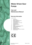
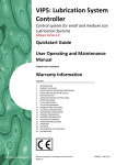
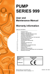
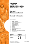
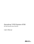
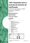
LOCOPUMP S2
Pneumatic Pump
User and Maintenance
Manual
Original text translation
Warranty
CONTENTS
1.
2.
3.
4.
5.
6.
7.
8.
9.
10.
11.
12.
13.
14.
15.
16.
17.
18.
http://www.dropsa.com
INTRODUCTION
GENERAL DESCRIPTION
IDENTIFICATION OF THE MACHINE
TECHNICAL CHARACTERISTICS
MACHINE COMPONENTS
UNPACKING AND INSTALLATION
INSTRUCTIONS FOR USE
PROBLEMS AND SOLUTIONS
MAINTENANCE PROCEDURES
DISPOSAL
INFORMATION ABOUT ORDERING
DIMENSIONS
HANDLING AND TRANSPORT
PRECAUTIONS FOR USE
OPERATIONAL HAZARDS
GUARANTEE
DECLARATION OF CONFORMITY
DISTRIBUTORS
Manual compiled in accordance with Directive
CE 06/42
C2123IE– WK 17/11
1. INTRODUCTION
This user and maintenance manual relates to the “LOCOPUMPS2”.
The latest version may be obtained from the Technical-Commercial Office, or by consulting our web site
http://www.dropsa.com.
This user and maintenance manual contains important information about protecting the health and safety of the personnel
who intend to use this apparatus. You must read and look after it carefully, making sure that it is available at all times for the
operators who intend to consult it.
2. GENERAL DESCRIPTION
The pneumatic pump “LOCOPUMP S2” uses compressed air to control the grease quantity which is delivered from the pump.
Hence, it should be used on machines where compressed air is readily available.
It 's a grease single effect pneumatic pump generally used in systems with single-line progressive dividers as SMX, SMO, SMP or
SMPM.
In the standard version the pump is fitted of a 2kg reservoir spring loaded, whereby the pump can easily provide grease NLGI 2.
The transparent reservoir allows to see clearly the amount of remaining grease moreover there is a minimum level sensor. This
pump is designed to mount a maximum level sensor and an adjustable delivery kit.
Loading connection is completed of a filter guaranteeing the input of clean lubricant into the reservoir.
It’s possible to use a filtered clean grease return in the reservoir.
3. IDENTIFICATION OF THE MACHINE
On the front part of the pump tank there is a plate which indicates the product code, the supply voltage and the basic
characteristics.
4. TECHNICAL CHARACTERISTICS
TECHNICAL CHARACTERISTICS
Pumping system
Single acting pneumatic piston
Air pressure
3÷6 bar
Compressed air inlet
G 1/8 UNI - ISO 228/1 with cone seating for 6mm tube
Reservoir refilling
grease nipple with check valve type
UNI 7663 – “A“ – 1/8“ NPT
Lubricant outlet
G ¼ UNI – ISO 228/1
Reservoir return
G ¼ UNI – ISO 228/1
Compression ratio
50:1
Fixed delivery
2 cm3/stroke
Adjustment delivery (kit 3133390)
0.5 ÷2 cm3/stroke
Max. grease consistence
NGLI 2
Piston total stroke
36.5 mm
Piston working stroke
Minimum level contact
29.2 mm
Operating temperature
+5 ÷ +50°C
Storage temperature
+5 ÷ +50°C
Relative humidity max. noncondensing operating damp
90%
Sound pressure level
< 70 db (A)
Weight
4.5 Kg
V max.= 100 Vac
I max.= 0.25° @ 30Vac
P max.= 7.5 W (NO) – 3 W (NC)
2/12
5. MACHINE COMPONENTS
The main part of the pump are:
The reservoir, constructed of transparent type plastic, compatible with commercially available greases.
The pump body , constructed of steel with capability of delivery upto 2 cm³ (0,12 cu.in) per stroke at a maximum pressure of
300 bar (4351 psi). There is an internal check valve mechanism for the grease output.
The level sensor, is and electric contact that indicates that the pump has reached its low level of grease. It's possible to set it to
either “Normally Closed” or “Normally Open” ( see drawing for further instruction ). As standard is set to “Normally Closed”.
PART NUMBER
3044260
3045202
3413502
1655183
712100
DESCRIPTION
Reservoir 2 Kg. (4,4 lb)
Support Bracket
Body pump
Minimum level sensor
Refilling Filter
3/12
5.1 PNEUMATIC GREASE PUMP WITH STANDARDIZED 400CC LUBRICANT CARTRIDGE LOADING SYSTEM
The Pneumatic Pump with cartridge grease loading is a pump for general use in single line
progressive divider lubrication systems such as SMX, SMO, SMP or SMPM.
The pump is designed for all those applications where it is ideal to have grease supplied in readily
available cartridges.
The pump is equipped with a steel plate with a M57x1.5 mm thread that allows interfacing with up to
two 400cc lubricant cartridges.
High Reliability is guaranteed by the use of hardened steel in the construction in all the pumping
element components and the pump piston is manufactured in ground hardened steel.
5.1.1 DIMENSIONS
B
A
C
D
E
A
115
OVERALL
DIMENSIONS
B
~480
QUOTE OF FASTENING
C
252
D
100
E
60
5.1.2 ORDER INFORMATION
3190372
PART NUMBER
3414064
0061117
3050564
0061117
3413502
3133390
3190372
0061117
3050564
3413500
3133390
DESCRIPTION
Pneumatic pump with cartridge
loading
SPARES
Seal gasket
Gasket
Flange connection
Pneumatic pump grease R= 50:1
Pump delivery adjustment kit
4/12
6. UNPACKING AND INSTALLATION
WARNING: The unit is only to be opened and repaired by specialist personnel.
6.1 UNPACKING
Once a suitable installation position has been identified, unpack the pump and prepare for installation. It is important to inspect
the pump to ensure that there has been no damage during transportation. The packaging material used does not require any
special disposal procedures. You should refer to you regional requirements.
6.2 PUMP INSTALLATION
Allow sufficient space for install with 150mm clear space around the perimeter of the pump.
Mount the pump LocopumpSerie2 at “eye level” to avoid any risk of postural problems.
Do not install the pump in dangerous environments such as explosive/flammable areas or in areas subject to high vibration.
Only use the fixing holes on the support bracket which are intended for n°2 holes for screws Ø10 mm (0,4 in.)(use a flat washer
with the screw ). For more details of the fixing holes please verify the dimensions shown on the drawing in chapter 12.
6.3 ELECTRICAL CONNECTIONS
Ensure the electrical connection of the low level is connected before using the pump. See below drawing for connection details.
A label of this drawing is also on the pump’s reservoir.
Supply voltage 24 V max.
6.4 PUMP OUTLET CONNECTION
The hydraulic connection of the pump is on the front face of the pump. It is a standard 1/4” BSP ( see drawing in chapter 12 ).
6.5 AIR CONNECTION ON PUMP
Use an 1/8” BSP connection fitting. It also possible to use DropsA’s nut an cone fittings as the seating is already available.
Remember to use a 3/2 valve that allows the air to vent to atmosphere and the internal spring within the pump to reset.
6.6 HOW TO ADJUST THE PUMP OUTPUT OR PRESSURE
This can be done by :Regulating pressure: the output pressure has a 50:1 ratio with the inlet pressure. Therefore this can be
regulated depending on the requirements of the system. (see chapter 4 for min and max pressures).
Regulating pump: as standard the pump has a fixed output. For special requirements you can convert the pump by installing the
kit 3133390 – ordered separately to the pump – the kit is shown below.
To use this kit , mount the o-ring ( A ) then tighten the fitting ( B ) with a 27mm spanner. Loosen the counternut (C) with a 13
mm spanner to unblock the screw (D), use the appropriate screw driver to screw IN for less output or screw OUT for more
output. After adjustments have been made you must tighen the counternut (C) to block any further movements.
N.B.: After all connections have been made please ensure that they are safe and properly secured down.
5/12
7. INSTRUCTIONS FOR USE
7.1 Start Up
The unit should only be used, opened and repaired by specialized personnel only.
It is prohibited to use the pump if it is submersed in fluid, in dangerous environments or explosive/flammable areas unless
pre-agreed with supplier and appropriate safety/protection measures have been put in place.
Use gloves and safety glasses as advised in the grease lubricant safety data sheet.
DO NOT use aggressive lubricants on the NBR seals, if in doubt consult DropsA Spa technical office who can offer advice on
lubricants and provide a pre-approved list of greases.
Ensure proper precaution to keep the pump clean and avoid and potential health hazards.
Always use suitably pressure rated tubing for the lubrication system.
7.2 Action to be taken before start-up.
Check the integrity of the pump.
Refill the tank with suitable lubricant.
Check that the pump is at working temperature and that there are no air bubbles in the pipes.
Check that the electric connection has been carried out correctly (CEI 64/8, IEC 364).
Ensure that the pump is properly connected to the control panel.
7.3 Use
Check the data sets imposed.
Press the start button on the machine to which the Sumo pump is connected.
Check pump start-up.
Check that the machine is adequately lubricated (if there are still some doubts about its correct functioning you can
contact the Dropsa S.p.A Technical Office and request a test procedure).
8. PROBLEMS AND SOLUTIONS
Below is a diagnostic table showing the main faults, the probable causes and the possible solutions.
In the event of doubts and/or problems which cannot be solved, do not proceed to look for the fault by dismantling parts of
the machine, but contact the Dropsa Technical Office.
DIAGNOSTIC TABLE
FAULT
The pump does not deliver grease or
does not deliver the correct amount of
grease
CAUSE
SOLUTION
The grease level is below minimum.
Add more grease into the reservoir without
surpassing the MAX level.
The solenoid valve on the inlet of the
pump does not vent.
Verify it the solenoid vents. Vent the
solenoid manually and monitor if the
grease flows out.
The fittings are leaving/loose.
Tighten the fittings and check for leaks on
all fittings.
Regulation of air inlet pressure..
Adjust the air pressure on the inlet of the
pump taking into account the pressure
ratio.
Internal Check valve is damaged or
contaminated.
Clean or change the valve shown in kit
3133391.
The pump does achieve required
pressure or does not maintain its
operating pressure.
6/12
9. MAINTENANCE PROCEDURES
Ensure the pump is positing so that it can be verified easily.
Ensure you have necessary personal protective equipment to avoid any contact with the grease.
The pump undergoes severe factory testing therefore no maintenance is forecasted with the pump.
DropsA recommends the use of lubricants that are free of any impurities as well as a regular cleaning of the pump’s
components.
The pump is dismantled as follows :
1.
2.
3.
4.
5.
6.
Before removing the reservoir is must be completely emptied of lubricant.
Disconnect the air inlet connection.
Disconnect all tubing on the pump.
Loosen the screws on the lid, remove the reservoir taking ABSOLUTE care of the spring inside the reservoir ( it may still be
under tension – if so remove more lubricant.)
Remove the pump and any filters if fitted.
Unscrew the plug on the pneumatic pump body , be careful of the load on the internal spring. At this point you can remove
the internal components of the pump body.
At this point all components are loose and allows the cleaning and verifying of each component possible.
All components must be clean with cleaning fluid and lubricated before re-assembly.
Periodically it is necessary to check:
CHECK
The lubrication status
Lubricant level
Clean refilling filter
Clean bottom of reservoir if deposits have formed.
TOTAL NUMBER OF PUMP CYCLES
100
200
400
600
The machine does not require any special equipment for any checking and/or maintenance activity, however the
recommendation is to use suitable equipment which is in a good condition (according to current regulation) in order to avoid
causing damage to persons or machine parts.
Make sure that the electric and hydraulic supply has been disconnected before carrying out any maintenance intervention.
10. DISPOSAL
In the course of machine maintenance, or if the machine is scrapped, do not dispose of polluting parts into the environment.
Refer to local regulations with regard to their correct disposal. When scrapping the machine the identification plate and any
other documents must be destroyed.
11. INFORMATION ABOUT ORDERING
PART NUMBER
3413050
3133391
3133390
3133392
3413050 C
FEATURES
Pneumatic pump R=50:1 Reservoir 2 Kg (4,4 lb)
Seal kit spares
Adjustable pump output kit
Kit max level
Preloaded pneumatic pump R=50:1 Reservoir 2 Kg (4,4 lb)
7/12
12. DIMENSIONS
To facilitate future maintenance, increase the spaces indicated by at least 100 mm.
8/12
13. HANDLING AND TRANSPORT
Prior to shipping, the equipment is carefully packed in cardboard package. During transportation and storage, always maintain
the pump the right way up as indicated on the box. On receipt check that package has not been damaged. Then, store the
machine in a dry location.
14. PRECAUTIONS FOR USE
It is necessary to carefully read the warnings and risks associated with using a lubricant pump. The operator must understand
how it works and must clearly understand the dangers by studying the user manual.
Power supply
Any type of intervention must not be carried out before unplugging the machine from power supply. Make sure that no one can
start it up again during the intervention.
All the installed electric and electronic equipment, reservoirs and basic components must be grounded.
Flammability
The lubricant generally used in lubrication systems is not flammable. However, it is advised to avoid contact with extremely hot
substances or naked flames.
Pressure
Prior to any intervention, check the absence of residual pressure in any branch of the lubricant circuit as it may cause oil sprays
when disassembling components or fittings.
Noise
Pump produces noise, not more than 70 dB(A).
15. OPERATIONAL HAZARDS
The check on compliance with the essential safety requirements and with the stipulations indicated in the machine directives
are to be carried out by means of compiling the checklists already made available and contained in the technical file.
Two types of lists were used:
List of dangers (section from UNI EN ISO 14121-1 relating to UNI EN ISO 12100)
Application of the essential safety requirements (Machine Dir.)
See below a list of dangers which have not been completely eliminated, but are considered acceptable:
During assembly/maintenance it is possible that there may be an oil splash (consequently this operation must be carried out
using appropriate individual protective devices);
contact with oil -> see instructions for using appropriate individual protective devices DPI;
Loaded springs, in the pump cylinder and in the reservoir.
Use of an inappropriate lubricant -> fluid characteristics indicated both on the pump and in the manual (if in doubt consult
our Technical Office);
protection against direct and indirect contact must be provided by the user;
The pump’s working logic requires it to operate at all times, so it is necessary to pay attention to the electric connection. If
there is no current the customer’s machine can only be restarted following a reset while the lubrication pump can restart
automatically.
Do not use alcahol or spirits to clean any components.
UNACCEPTABLE FLUIDS
Fluids
Lubricant with abrasive additives
Lubricant with silicon additives
Benzine – solvents – inflammable liquids
Corrosive products
Water
Food substances
Dangers
High consumption of contaminated parts
Jamming of the pump
Fire – explosion – damage to gaskets
Corrosion of the pump – injuries to persons
Pump oxidation
Contamination of these substances
9/12
16. WARRANTY
All Dropsa products are guaranteed for a maximum of 12 months from the delivery date, for constructional and material faults.
The guarantee is extended as indicated below:
Complete installation of the system by Dropsa: 24 months.
Other components: 12 months from the date of installation; if installation takes place 6 months or more following the delivery
date, the guarantee will cover a maximum of 18 months from the delivery date.
In the event of equipment malfunction we must be notified of precise details of the fault encountered, supplying the Dropsa
code, the test number if present (expressed as: xxxxxx-xxxxxx), delivery and installation date and, finally, conditions of using the
product/s in question.
Once this information has been received we will decide at our own discretion whether to provide technical assistance or to
provide a return authorisation number (RAN) with precise instructions about returning the equipment.
After receiving the equipment and on the basis of careful analysis Dropsa reserves the right to decide whether to repair or
replace the product. If the guarantee is still valid we will proceed to repair or replace the part at our own expense.
If the returned product is not faulty, Dropsa will decide at its own discretion whether or not to charge the customer for the costs
incurred (logistics etc.).
This guarantee must be understood to be cancelled if the product shows signs of damage and resulting from incorrect use,
negligence, normal wear and tear, chemical corrosion, installation not in compliance with the instructions expressly indicated
and use contrary to the manufacturer’s recommendations. Any changes, tampering or alterations to the equipment or its parts
made without written authorisation from Dropsa S.p.A., relieves the latter from all liability and releases it from the obligations
of the guarantee.
Parts subject to normal wear and tear and perishable parts are not covered by the guarantee.
Anything not expressly indicated must be considered to be excluded from the guarantee as well as damages or costs resulting
from faults in the actual product.
The conditions of validity of the Dropsa guarantee are understood to be implicitly accepted as soon as the equipment is
purchased. Any changes to or departures from this guarantee must only be considered valid after prior authorisation from
Dropsa S.p.A.
DROPSA S.p.A. declines any liability for personal injuries or damages to property in the event of failure to comply with the
instructions provided in this manual.
Any changes to the component parts of the system or a change in the intended use of the latter or its parts without written
authorisation from DROPSA S.p.A. relieve the latter from any liability for personal injuries and/or damage to property and
relieve it of any guarantee obligation.
10/12
17. DECLARATION OF CONFORMITY
Dropsa Spa
Via Benedetto Croce, 1
20090 Vimodrone (MI)
Italy
Tel.:
Fax Sales:
E-mail:
Web site:
(+39) 02. 250.79.1
(+39) 02. 250.79.767
[email protected]
http://www.dropsa.com
DICHIARAZIONE
DI CONFORMITÁ/DECLARATION OF COMPLIANCE WITH STANDARDS/
DECLARATION DE CONFORMITE/ KONFORMITÄTSERKLÄRUNG DES STANDARDS /DECLARACIÓN DE
CONFORMIDAD/ DECLARAÇÃO DE CONFORMIDADE
La società Dropsa S.p.A., con sede legale in Milano, Via Besana,5/ Dropsa S.p.A., registered office in Milan,
Via Besana,5 / Dropsa S.p.A. au Siège Social à Milan, Via Besana,5/ Dropsa S.p.A., Sitz in Milano, Via
Besana 5/ La sociedad Dropsa S.p.a., con sede legal en Milán, Via Besana,5/ A Dropsa S.p.A, com sede em
Milão, via Besana, nº 5
DICHIARA /CERTIFIES / CERTIFIE/ ZERTIFIZIERT, DASS/ DECLARA/ CERTIFICA:
che la macchina denominata/that the machine named / que la machine dénommée/ Die Maschine mit
der Bezeichnung/ que la máquina denominada/ que o equipamento denominado
“LOCOPUMP Serie2” code 3413..
è conforme alle condizioni previste dalle Direttive CEE /has been constructed in conformity with the
Directives Of The Council Of The European Community on the standardization of the legislations of
member states/ a été construite en conformité avec les Directives Du Conseil Des Communautes
Europeennes/ Entsprechend den Richtlinien des Rates Der Europäischen Union, für die Standarisierung
der Legislative der Mitgliederstaaten, konstruiert wurde/ cumple con las condiciones establecidas por las
directivas comunitarias/ foi construído em conformidade com as diretivas do Conselho das Comunidades
Europeias:
2006/42 Direttiva macchine /Machinery Directive / 2006/42 Directive machines / Maschinenrichtlinien/
Maquinaria 2006/42/CEE /Directiva 2006/42 Máquinas;
Vimodrone (MI), April 2011
Technical Director:
Maurizio Greco
…………………………
Legal representative
Milena Gavazzi
…………………………
11/12
18. DISTRIBUTORS
Dropsa S.p.A.
Via B. Croce,1
20090 Vimodrone (MI) Italy.
Tel: (+39) 02 - 250.79.1
Fax: (+39) 02 - 250.79.767
E-mail: [email protected] (Export)
E-mail: [email protected] (National)
Dropsa Ame
23, Av.des.Morillons
Z.I. des Doucettes 91140
Garges Les Gonesse, France
Tel: (+33) 01 39 93 00 33
Fax: (+33) 01 39 86 26 36
E-mail: [email protected]
Dropsa (UK) Ltd
Unit 6, Egham Business Village,
Egham,Surrey,TW20 8RB
Tel: (+44) 01784 - 431177
Fax: (+44) 01784 - 438598
E-mail: [email protected]
Dropsa do Brazil Ind. E Com. Ltda
Rua Sobralia 175,
Sao Paulo, Brazil
Tel: (+55) 011-5631-0007
Fax: (+55) 011-5631-9408
E-mail: [email protected]
Dropsa USA Inc.
6645 Burroughs Ave
48314-2132 Srerling Hts,Mi Us -USA
Tel: (+1) 586-566-1540
Fax: (+1) 586-566-1541
E-mail: [email protected]
Dropsa Lubrication Systems
Nr 8 Dongxing Road,
Songjiang Industrial Zone
(Shanghai) Co., Ltd
Tel: +86 (021) 67740275
Fax: +86 (021) 67740205
E-mail: [email protected]
Dropsa Gmbh
Volmerswerther Strasse 80
40221 Dusseldorf 1, Deutschland
Tel: (+49) 0211/39 4011
Fax:(+49) 0211/39 4013
E-mail: [email protected]
Dropsa Australia Pty.
C20/148 Old Pittwater Road
Brookvale, NSW 2100
Tel: +61 (02) 9938 6644
Fax: +61 (02) 99 386 611
E-mail: [email protected]
Web site: http://www.dropsa.com - E-mail: [email protected]
12/12