1
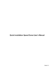
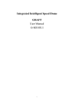
CODE
DMX Lighting Controller
User’s Manual
Ver 1.2
CODE ELECTRONIC CO., LTD.
CODE A12 Lighting controller User’s Manual
Introduction
Using standard DMX512 protocol, CODE A12 DMX Lighting Controller can directly control any dimmer, which
follows the same protocol, to buildup a small digital lighting control system. Light scenes can be saved and
chase programs can be edited. Internal chase programs, which were set in CODE A12 by manufacturer, can
be utilized directly. 1 manual light scene, 4 submaster light scenes and 1 chase program can be performed at
the same time. CODE A12 is suitable for small TV studio, small show, small ballroom, taproom and so on.
Functions and Specifications:
Output of DMX512 signal.
12 lighting channels.
4 submaster light scenes, which can be saved and edited.
12 editable and savable chase program and up to 12 steps in a chase program.
Chase speed can be controlled manually (0.3s~10s/step) or triggered by music rhythm.
Music signal can be inputted from audio line (-10~+10dB self adapted) or picked up by internal
microphone.
1 manual light scene, 4 submaster light scenes and 1 chase program can be performed at the same
time.
Channel flash key, submaster flash key and master flash key.
Port of DMX512 output: XLR-D3F
Port of music input: 1/4” mono audio socket, imbalance mode.
Power: AC 90~250V,50-60Hz,4W
Size: 482mm X 178mm X 65mm
Weight: 2.6Kg
Cautions for safety
A12 lighting controller must be connected to earth ground to ensure the safety.
When A12 and lighting adjusters are working, don’t plug in or pull out DMX512 data cable.
Don’t splash any liquid to the lighting controller.
The lighting controller is precision electric equipment. Please pay attention to moistureproof protection
and dustproof protection.
Installation
Contents in the package of A12 lighting controller:
A12 lighting controller
1;
Power supply line
1;
Certification of QC
1;
User’s Manual
1.
Installing structure of A12 lighting controller follows international standard 19” 4U. It can be embedded in
operation board or directly installed in 19” shelf or cabinet.
Before the power supply is connected, please check whether the voltage is in normal range of A12 and
whether the power supply socket is connected to earth ground.
1
CODE A12 Lighting controller User’s Manual
Panel of A12
1.
Power switch
Close or open the power of A12 lighting controller. When the power is off, the controller can save the last
state automatically and run it continually next time.
2.
Save to Submaster
Save current level of every channel to submaster slider set by user.
3.
Ch1~Ch12 slider
Ch1~Ch12 slider is used to control the level of different channel.
4.
Chase key
The key has three functions:
Pressing chase key quickly can switch between flash control state and chase program state.
Pressing chase key for more than 2 seconds can make the controller into chase program edit
state.
When LED of chase key is in different states, number key 1-12 corresponding to slider has different
functions.
LED Display
Illustration
When LED of Chase key is off, number key 1-12 is in flash control
state. Pressing a number key made the output of corresponding
channel slider to the maximum. Releasing the number key will
resume the level set by the corresponding slider.
When LED of Chase key is on, 12 number keys correspond to 12
chase programs.
When LED of Chase key is blinking, the controller is in chase
program edit state.
5.
Number key
When chase key is in different states, number key 1-12 has different functions.
When LED of Chase key is off, number key 1-12 is in flash control state.
Pressing a number key made the output of corresponding channel slider to the maximum.
Releasing the number key will resume the level set by the corresponding slider.
When LED of number key is blinking, corresponding chase program is running.
2
CODE A12 Lighting controller User’s Manual
When LED of Chase key is on, 12 number keys correspond to 12 chase programs.
Pressing a number key will output a corresponding chase program.
6.
Submaster slider
Light scene is the collection of level value of each channel.
Each submaster slider can save a light scene. Move the slider can change the level of light scene.
7.
Submaster flash key
In flash control state, pressing a number key made the output of corresponding submaster slider to the
maximum. Releasing the number key will resume the level set by the corresponding slider.
8.
Music key
Press music key to make its LED on, chase program is triggered by music rhythm. Press music key
again to make its LED off, chase speed is controlled by speed slider.
9.
Master flash key
Pressing the key made the output of master slider to the maximum. Releasing the number key will
resume the level set by the master slider.
10. Master slider
It is general control of level of every submaster slider and every channel slider.
11. Speed slider
Move speed slider to control chase speed.
Rear of A12
Connection of power supply
Power supply line has a three-foot plug, which follows the standard of P. R. China. The power supply socket
must be connected to earth ground to ensure the safety.
The power of A12 lighting controller has steady voltage output in so wide range of power supply voltage that
it is adapted to the power supply of many countries. Before the power supply is connected, please check
whether the voltage is in normal range of A12 to ensure the safety.
3
CODE A12 Lighting controller User’s Manual
Power fuse
When the fuse needs to be replaced, please use the fuse with the current capacity signed on the rear of A12.
Audio signal input
There are a 1/4” mono audio socket and an internal microphone in A12 lighting controller. When audio input
line is plugged into audio socket, rhythm of input music is used as trigger signal of chase program. When
audio input line is pulled out from audio socket, rhythm of environment sound picked up by internal
microphone is used as trigger signal of chase program.
Output of DMX signal
There is a XLR3 output socket on the rear of A12. Please connect plug of DMX as following:
Foot of socket/plug
1
2
3
Illustration
Earth ground of DMX
Signal Signal +
DMX512 signal cable
According to DMX512 protocol, DMX signal cable must be screened twist cable with impedance of 120Ω.
The length of cable should not be over 250m. Pin 2 and pin 3 of the plug can not be confused, please
distinguish two lines of twist cable by different colors.
Connection of DMX512 signal
The connection between DMX512 signal and other equipment is a “chrysanthemum chain” mode. DMX521
signal is sent from A12 lighting controller output to DMX512 input of the first silicon box. Then it is sent from
DMX512 output of the first silicon box to DMX512 input of the second silicon box and goes on like this.
An 120Ωterminal matching resistance must be connected to the last equipment to prevent reflection and
aberration of signal. The operation is as following: connect a 120Ωresistance to pin 2 and pin 3 of a plug then
plug it to the output of the last scanner equipment.
Address distribution of DMX512
A12 lighting controller uses channel data address 1-12 of DMX512 protocol. If two 6-channel silicon boxes
are connected, the receiving address of the first one is set to “1” and that of the second one is set to “7”.
4
CODE A12 Lighting controller User’s Manual
Submaster edit
1.
Push Master slider to the maximum.
2.
Use Ch1~Ch24 slider to control the brightness of different channel to compose a light scene.
3.
Press Save to Sub key to make its LED blinking. Then press the number key corresponding to the
submaster slider, which the scene is wanted to be saved to. (For example, if current scene is wanted to
be saved to submaster slider 1, Save to Sub key is pressed first, then number key 1 is pressed.)
Edit of chase program
1.
Press Chase key for about 2 seconds to make its LED blinking. A12 is in chase program edit state.
2.
Choose chase program number.
For example, if chase program 1 is wanted to be edited, number key 1 is pressed. Its LED will be
blinking.
If this chase program is not empty, its LED will indicate how many steps are there in the program.
3.
Choose chase step number. If start from step 1, number key 1 is pressed.
4.
Use Ch1~Ch24 slider to set the level of different channel of this step.
5.
Repeat step 3-4 to set the level of different channel of next chase step.
6.
In program edit process, press number key 1-12 to check the lighting effect of every chase step.
7.
Press Chase key for about 2 seconds to quit from program edit state.
Attention: when quit from program edit state, the controller set the current chase step as the last chase
step automatically.
Chase program starts from chase step 1 to the last step and then goes back to step 1 to start a new
circle.
For example, chase steps 1 to 10 have been edited. Before quitting from chase program edit state,
number key 8 is pressed. So step 8 is current step. So only steps 1 to 8 of the chase program can be
run circularly.
Running of chase program
When LED of chase key is on, number key 1-12 corresponds to chase program.
For example, pressing number key 3 will running chase program 3. Change speed of chase program via
speed slider.
Speed control
When LED of music key is off, moving speed slider can change the speed of running chase program.
Music trigger
When music key is pressed, its LED is on. Chase program is triggered by low frequency rhythm of music.
When audio input line is connected, rhythm of input music is used as trigger signal. Otherwise, rhythm of
environment sound picked up by internal microphone is used as trigger signal.
5
M E M O
CODE Electronic Co., Ltd.