1
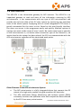
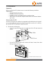
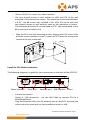
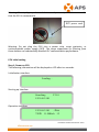
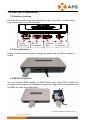
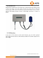
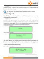
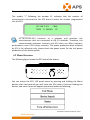
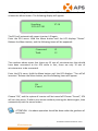
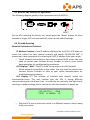
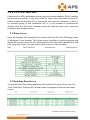
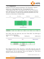
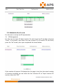
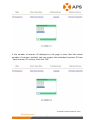
Altenergy Power System
Energy Communication Unit
(ECU)
Installation and User Manual
(For ECU-3 V3.10)
ALTENERGY POWER SYSTEM INC.
All rights reserved
`
TABLE OF CONTENTS
1.0 Introduction..................................................................................................2
2.0 Installation................................................................................................... 3
3.0 Interface Explanation...................................................................................8
3.1 Interface position................................................................................. 8
3.2 Power Interface....................................................................................8
3.3 RS232 Serial Port................................................................................ 8
3.4 Network Port........................................................................................9
3.5 USB Interface...................................................................................... 9
3.6 RESET............................................................................................... 10
4.0 Basic Operation......................................................................................... 10
4.1 Power Up........................................................................................... 10
4.2 Menu Structure.................................................................................. 11
4.3 Restore the factory set operation....................................................... 13
4.4 Troubleshooting................................................................................. 13
5.0 ECU Local Interface.................................................................................. 14
5.1 Home Screen......................................................................................14
5.2 Real-time Data Screen....................................................................... 14
5.3 Configuration.....................................................................................15
5.4 Administration Screen....................................................................... 16
6.0 Technical Data........................................................................................... 22
1
Version:6.0
1.0 Introduction
The APS-ECU is the information gateway for APS inverters. The APS-ECU is an
important gateway to read and store all the information returning by APS
microinverters. It can communicate with any type of APS microinverters and
provide the real-time data of the PV solar system by monitoring the operation
state of the whole system. Equipping with an inside integrated HTTP server is
greatly convenient for the users to visit. Based on the user-friendly interface,
the users can access in the programme easily and quickly. Multiple options in
settings can meet a wide scope of users’ needs. No matter what type or quantity
of the microinverters is, no matter what connection type of the network is, no
matter how far the system has been placed, the ECU can communicate with the
APS microinverter regardless of the mentioned weak points.
Other Elements in the APS microinverter System
The APS microinverter is a fully integrated device that converts the DC
output of a single solar module into grid-compliant AC electricity.
The APS web-based Energy Monitoring and Analysis system (EMA)
constantly monitors the operation state and analyzes the data collected
by the ECU from every microinverter.
2
Version:6.0
2.0 Installation
Preparation
Before installing the ECU, please ensure to meet the following installation
requirements:
· Standard AC electrical outlet
· Broadband Internet connection
· Broadband router with Ethernet port or wireless router
· Web browser to view EMA. Support web browsers are Internet Explore
and Firefox
Find a Location for ECU
The ECU can be place on a table or be mounted on the distribution ark and wall.
It is recommended that location for the ECU should be dry and cool. In addition,
do not cover the ECU and keep it away from dust.
1) Distribution ark Mounting
· Loosen the two M3 screws that are at the back of the ECU and rotate the
holders.
182mm
42mm
Holder
M3 Screw
113mm
· Fix the ECU on the frame with screws and keep it away from other
heat-generating devices.
80mm
138mm
3
Version:6.0
2) Wall Mounting
· Mount the ECU in a cool, dry, indoor location.
· Use two drywall screws or wall anchors to affix the ECU to the wall
mounted at the dimensions shown. The maximum screw head diameter
is 0.35’’. Use #8 screws (not included in kit). Affix ECU to the wall with
two drywall screws or wall anchors same as the indication as below .
The maximum diameter of a screw head is 0.35’’. We recommend to use
#8 screws (not included in kit).
· Slide the ECU onto the mounting screws, aligning the ECU screw holes
with the screws installed in step 2. Lower the ECU onto the screw posts
to secure the unit to the wall.
130mm
Install the ECU Cable Connections
The following diagram is a guide for the connections on the back of the APS ECU.
Power interface
Serial port
Network port
USB interface
Reset
· Connect to Internet
Option 1: LAN connection - use the LAN Cable to connect ECU to a
Broadband Router.
Plug the Ethernet cable into the network port on the ECU, and plug the
other end into a spare port on the broadband router or LAN.
4
Version:6.0
Illustrated as follows:
①
ECU
LAN
cable
ROUTER
LAN
cable
COMPUTER
Without the internet, you can also visit the local web on ECU. Connect
one of the network cable ends to ECU and the other to your PC. Then
set up the network following steps (e.g. Windows 7): Open Network
Connections by clicking the “Start” button, and then clicking “Control
Panel”. In the search box, type “adapter”, and then, under Network and
Sharing Center, click “View network connections”. Right-click the
connection that you want to change, and then click “Properties”. If
you're prompted for an administrator password or confirmation, type
the password or provide confirmation. Click the “Networking” tab.
Under “This connection uses the following items”, click “Internet
Protocol Version 4 (TCP/IPv4)”, and then click “Properties”. Click “Use
the following IP address”, and then, in the “IP address” box, type
60.190.131.227, in the “Subnet mask” box, type 255.0.0.0, and then
click “OK”.
ECU
2:
② Option
LAN
cable
COMPUTER
WiFi connection – use WiFi bridge to connect ECU to a Broadband
Router.
Configure the WiFi Bridge to connect to Wireless Router, please refer to
WiFi Bridge User Manual
Connect the RJ45 LAN Cable and USB Cable on WiFi Bridge to the RJ45
Port and USB Port on ECU
The ECU needs to have a access of a Dynamic Host Configuration
Protocol (DHCP) IP address which can be connected to the Internet. The
ECU will only search for a DHCP IP address during its power up
sequence. ECU will automatically obtain the IP address, such as:
139.168.200.65, and connect to Internet. If the IP address shows
“60.190.131.228”, it means ECU fails to get IP address. Make sure the
connection between ECU and Router is working well. If not, please
reboot ECU and try to obtain IP address again.
· Plug the AC power cord into the AC input on the ECU, and then plug the
other end into a standard AC electricity outlet.
5
Version:6.0
Warning: Do not plug any electrical devices and power strip into the same outlet
that the ECU is connected to.
ECU power cord
Warning: Do not plug the ECU into a power strip, surge protector, or
uninterruptable power supply (UPS). The surge suppression or filtering from
these devices can substantially diminish PLC communication performance.
ECU initial setting
Step 1: Power on ECU
The following information will be displayed on LCD after ten seconds.
Initialization Interface:
Loading…
Starting up Interface:
Searching
192.168.2.101
V3.10
Operation interface:
192.168.2.101
+Web
750W 11.54Kwh 12
6
Version:6.0
When the communication between the ECU and inverters goes successfully, the
LCD will show the readings of your system. The data in operation interface
includes:
· Local IP address, for example: 192.169.2.101 (your actual local IP
address will be different)
· Web connection information: “+Web”. it means the ECU is connected to
EMA. If it is “–Web”, Internet itself has a problem. Need to setup the
security authority to offer Auto IP configuration.
· Data of the present power-production in watts, for example: 750W
· Data of the life time output of the system in kWh, for example:
11.54kWh
· The number of online microinverters producing power and reporting in
to the ECU, for example: 12
Step 2: ECU time zone setting
· Enter the IP address shown on the ECU LCD into the internet browser,
and then open the web page.
· Click “Administration”, then “Date, Time, Time zone”. In the
corresponding box, enter local date/time/time zone, click Update after
finished. For details, refer to 5.4.2 time management.
Step 3: EMA Monitoring
After ECU display “+web”,contact APS technical staffs in your local area and they
will setup an EMA account with User Name and Password.
7
Version:6.0
3.0 Interface Explanation
3.1 Interface position
All of the ECU interface as below, from left to right, are power interface, serial
port, network port and USB interface:
Power
interface
RS232
serial port
network
port
USB
interface
3.2 Power Interface
Power interface connects power through the power line, connection mode as
below:
3.3 RS232 Serial Port
You can connect GPRS module to RS232 serial port, select GPRS module to
connect to the network on “Network Connectivity” page, and communicate with
the EMA, to check the system data.
8
Version:6.0
3.4 Network Port
RJ45 Ethernet network port: ECU allows user to communicate with EMA, and log
in ECU's local page, set up the system and view the system data via Ethernet
network port. In the case of the absence of the wired network, user can select
optional WiFi-Bridge wireless Internet. WiFi-Bridge connection is shown as
below:
3.5 USB Interface
In the case of the absence of the wired network, user can select optional
WiFi-Bridge wireless Internet. USB interface provides 5V DC power supply for the
WiFi-Bridge.
9
Version:6.0
3.6 RESET
press the “Reset” button for three seconds or longer, ECU will automatically
return to the default settings.
ATTENTION:The historical power generation won't be cleared.
4.0 Basic Operation
The APS ECU has one two-line, 40-character LCD display with alphanumeric. Set
the mode using a single button.
4.1 Power Up
As soon as the ECU is plugged into an AC outlet, it will power up and display
several information on screen. The ECU will be ready to work less than in five
minutes after powering up. The ECU has completed booting up and has started
normal operation when it displays the following information:
Initialization Interface:
Loading…
Work Started Interface:
Searching
V3.10
192.168.2.101
The V3.10 indicates the firmware version from which the ECU’s operation and
features are dictated. After the ECU receives an IP address and establishes an
Internet connection, the ECU will contact a Network Time Protocol (NTP) server
so that it can set an accurate local time.
Normal Work Interface:
192.168.2.101
+Web
750W 11.54kWh 12
10
Version:6.0
The number 12 indicates the number of panels to which the ECU is connected.
The symbol “!” following the number 12 indicates that the number of
microinverters connected to the ECU doesn’t match the number programmed
into the ECU.
192.168.2.101
+Web
750W 11.54kWh 12!
ATTENTION:ECU functions as a gateway and monitors the
microinverters that are connected to the PV modules. Therefore, the
communication between inverters and ECU does not affect inverters'
performance, even if ECU drops inverters. The power production data collected
by ECU is for reference only, please check the power meter for the real power
production of the whole system.
4.2 Menu Structure
The following figure shows the ECU side of the button:
You can access the ECU LCD panel menu by pressing and holding the Menu
button; after two seconds you will enter the ECU menu. Continue holding the
button, and menu items will appear operational orders as following:
11
Version:6.0
Continue holding the Menu button. When the LCD displays “Device Search,”
release the Menu button. The following display will appear:
Searching
192.168.2.101
V3.10
The ECU will automatically report inverter’s ID again.
Enter the ECU menu. Hold the Menu button until the LCD displays “Status”.
Release the Menu button, and the following items will be appeared:
Connected:
Total:
12
15
The numbers above mean that there are 15 sets of microinverters that should
have been connected to the ECU while in fact, there are only 12 sets of
microinverters to be connected.
Enter the ECU menu. Hold the Menu button until the LCD displays: “Turn off all
inverters.” Release the Menu button, and the following items will appear:
Ok
Cancel
Choose “Ok”, and the system of inverter will be turned off. Choose “Cancel”, ECU
will exit the menu. If within one minute without pressing the button again, then
automatically exit the menu button.
ATTENTION:the above operation should be done under the guidance of
technicist.
12
Version:6.0
4.3 Restore the factory set operation
The following diagram guides to the connectors back of APS-ECU.
RESET
For the ECU restoring the factory set, simply press the “Reset” button for three
seconds or longer, ECU will automatically return to the default settings.
4.4 Troubleshooting
Potential Problems and Solutions
IP Address Problem: If the IP address displayed on the ECU’s LCD does not
match the subnet on your internal network and shows “60.190.131.228”, it
means that it was unsuccessful in obtaining a DHCP IP address from your router.
· Check network connectivity to the router or other DHCP server. You may
need to contact your Internet Service Provider or refer to your router
documentation for troubleshooting assistance.
LCD Displays “-Web”: The ECU could not connect to the APS website.
· Check network connectivity to the router. You may need to contact your
Internet Service Provider or refer to your router documentation for
troubleshooting assistance.
LCD Display “!”: The number of installed units doesn’t match the
microinverter-count. This may indicate that the ECU is having difficulty
communicating over the power lines. It could also be caused by low light levels,
resulting in module voltage that is too low for the microinverter to power up.
192.168.2.101 +Web
750W 11.54kWh 12!
· Plug the ECU into an electrical socket in a different location. Keep it away
from your router.
13
Version:6.0
5.0 ECU Local Interface
Connection to APS’s web-based monitoring and analysis website (EMA) requires
an Internet connection. If the users want to check data information form ECU,
please make sure that the ECU is connected with internet. However, if there is
no Internet access at the installation site, it is still possible to communicate
directly with the ECU local interface using the Ethernet port and a personal
computer with a web browser.
5.1 Home Screen
Once the browser has successfully connected with the ECU, the following screen
is displayed in the browser. This home screen provides a system overview and
shows the current status of the microinverters that have been identified by the
ECU. From this screen, you can access other screens in the interface.
5.2 Real-time Data Screen
To view the real-time system operation data statistics for your solar array, click
“Real Time Data” from the ECU home screen to navigate to the real-time data
screen.
14
Version:6.0
5.3 Configuration
Configure the inverter protection parameters. Click “Parameters”, type the
values in the “Undervoltage Slow” box, “Overvoltage Slow” box,
“Underfrequency Slow” box, “Overfrequency Slow” box and “Grid Recovery
Time” box, then click “Save”, the inverters’ protection parameters will be set.
Then click “Parameters” to view the actual protection parameters set on the
inverters in a few minutes. As shown below:
Click “GFDI”, select the check box, then click “Clear GFDI”. The GFDI flag of
inverters will be cleared soon.
Click “Remote Control”, select “Turn On” or “Turn Off” check box, then click
“Turn On/Off” to turn on or turn off inverters. The inverters will be turned on or
turned off soon. You can also click “Turn on all inverters” or “Turn off all
inverters” to turn on or turn off all inverters.
15
Version:6.0
5.4 Administration Screen
For the user to set up the ECU parameters
1) ID Management
For the user to input 12 digits inverter ID, each input the ID number and press
"Enter" a line break, then enter the next inverter ID, all inverter ID into finish,
press the "ok" button, the input completed. As shown below:
If the number of inverter ID displayed on the page is less than the actual number
of inverters installed, you can enter the lost inverters ID to “Input Inverter ID”
section, then click “OK”.
16
Version:6.0
If the number of inverter ID displayed on the page is more than the actual
number of inverters installed, you can remove the redundant inverters ID from
“Input Inverter ID” section, then click “OK”.
17
Version:6.0
If the inverter ID displayed on the page is discrepancy with the actual inverters
ID installed, please modified the wrong inverters ID from “Input Inverter ID”
section, then click “OK”.
18
Version:6.0
Click “Clear ID”, ID will be cleared.
19
Version:6.0
2)
Time management
In date column, input date, format for day/month/year, in time column, input
time, format for hour/minute/second, after the completion of the input, click on
the "ok" button. The ECU also can connect to the NTP server for obtaining
accurate date and time automatically. In "NTP server" Spaces place, users can set
NTP server address. As shown below:
3)
Language management. Users can switch language between Chinese and
English. As shown below:
4)
Network management. Users can choose to connect to the internet through
GPRS or Ethernet by setting the ECU internet connection modes. Check
“Use GPRS Module” and click “update” to run the GPRS module. Uncheck
“Use GPRS Module” and click “update” to use Ethernet. Checking “Use
DHCP” and clicking “update”, ECU can automatically acquire a dynamic IP
address from Ethernet. To use a static IP address, you need to fulfill the IP
address, Netmask, Gateway IP, Primary DNS Server and Secondary DNS
Server got from network administrator.
20
Version:6.0
Notes: The network cable in the package is used for the users to
connect the ECU with PC directly. One side is connected with the
ECU and the other side is connected with the PC. Then change the
IP address and the network mask into 60.190.131.1 and 255.0.0.0
respectively.
21
Version:6.0
6.0 Technical Data
Model: ECU-3
Communication Interface
Power Line
APS Proprietary
Ethernet
10/100M Auto-sensing, Auto-negotiation
USB interface
Standard
RS232
Standard
Power Requirements
AC Outlet
110 ~ 240 VAC, 50 ~ 60 Hz
Power Consumption
2.5 W
Mechanical Data
Dimensions(W×H×D)
182 mm×113 mm×42 mm
Weight
Ambient Temperature
Range
Cooling
Enclosure Environmental
Rating
Features
Standard Warranty
Term
380 g
Compliance
-40°C to +65°C
Nature Convection; No Fans
Indoor - NEMA 1(IP30)
3 Years
IEC 60950-1, EN60950-1, IEC 60529, EN 60529,
ANSI/UL 60950-1, CAN/CSA C22.2 No.60950-1,
UL50E, FCC part 15, EN61000-6-1,
EN61000-6-3, ICES-003, AS NZS 60950-1,
GB/T17799
This device complies with part 15 of the FCC Rules. Operation is subject to the
following two conditions: (1) This device may not cause harmful interference,
and (2) this device must accept any interference received, including interference
that may cause undesired operation.
This Class B digital apparatus complies with Canadian ICES-003.
22
Version:6.0
Disposal of your old appliance
1. When this crossed-out wheeled bin symbol is attached to a product, it
means the product is covered by the European Directive 2002/96/EC.
2. All electrical and electronic products should be disposed of separately from
the municipal waste stream via designated collection facilities appointed by
the government or the local authorities.
3. The correct disposal of your old appliance will help prevent potential
negative consequences for the environment and human health.
4. For more detailed information about disposal of your old appliance, please
contact your city office, waste disposal service or the shop where you
purchased the product.
23
Version:6.0
Contact Information
ALTENERGY POWER SYSTEM Inc.
1 Yatai Road, Jiaxing, PR China 314050
Phone: +86-21-68889199
Fax: +86-21-33928752
www.APSmicroinverter.com
24
Version:6.0