1
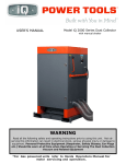
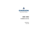
www.antech.com.tr POOLSAVER TETRA Please read this user manual completely. Do not throw. Damages resulting from usage errors are not covered by warranty. 1. GENERAL USER INFORMATION .......................................................................................................................... 2 2. DESCRIPTION AND PROPERTIES ........................................................................................................................ 3 2.1. DESCRIPTION ................................................................................................................................................. 3 2.2. GENERAL PROPERTIES ................................................................................................................................ 3 2.3. MECHANICAL DESIGN ................................................................................................................................... 3 2.4. ELECTRICAL DESIGN ..................................................................................................................................... 3 2.5. TECHNICAL PROPERTIES ............................................................................................................................. 4 3. INSTALLATION ....................................................................................................................................................... 6 3.1. MONTAGE ........................................................................................................................................................ 6 3.2. ELECTRICAL CONNECTION .......................................................................................................................... 7 3.3. ELECTRODE CHOICE ..................................................................................................................................... 8 4. USAGE ..................................................................................................................................................................... 8 4.1. LEDS AND DESCRIPTIONS ............................................................................................................................ 8 4.2. MODE SETTING .............................................................................................................................................. 9 4.3. SET VALUE SETTINGS ................................................................................................................................... 9 4.4. ELECTRODE CALIBRATION ......................................................................................................................... 10 4.5. PARAMETER SETTINGS .............................................................................................................................. 11 4.6. PARAMETERS ............................................................................................................................................... 12 4.7. OUTPUT CONTROL MODES ........................................................................................................................ 12 4.8. PROPORTIONAL CONTROL ........................................................................................................................ 13 4.9. RUN MODE CANCEL FUNCTION ................................................................................................................. 13 4.10. PASSWORD USAGE ................................................................................................................................... 13 4.11. WARNING AND FAILURE NOTIFICATION ................................................................................................. 13 4.11.1. rLO (RangeL) NOTIFICATION ............................................................................................................ 14 4.11.2. rHI (RangeH) NOTIFICATION ............................................................................................................. 14 4.11.3. LL (Level) NOTIFICATION................................................................................................................... 14 4.11.4. ErC (Electrode) NOTIFICATION .......................................................................................................... 14 4.11.5. LLO (Limit Low) NOTIFICATION ......................................................................................................... 14 4.11.6. LHI (Limit High) NOTIFICATION ......................................................................................................... 14 4.11.7. t0 (WDT) NOTIFICATION .................................................................................................................... 15 4.11.8. SdLy (Startup Delay) NOTIFICATION ................................................................................................. 15 5. SERVICE ................................................................................................................................................................ 15 5.1. FAILURES ...................................................................................................................................................... 15 5.2 WARNING AND FAILURE NOTIFICATION TABLE ........................................................................................ 16 6. GUARANTEE ......................................................................................................................................................... 16 6.1. GUARANTEE ................................................................................................................................................. 16 7. STANDARDS ......................................................................................................................................................... 17 22.04.14 Page 1/17 POOLSAVER TETRA 1. General User Information Please read the following information carefully and completely. This information will allow the user to ensure maximum benefit from instructions for use. WARNING This sign is used for situations where there is potential risk. Ignoring this sign may cause directly life-threatening or serious injuries. CAUTION This sign is used for situations where there is potential risk. Ignoring this sign may cause serious injuries or damaging of the product. IMPORTANT This sign is used for potential damages. Ignoring this sign may cause damaging of the product. SECURITY INFORMATION CAUTION Electrodes must be calibrate/control periodically because the accurate measurement and dosing is possible only when the electrodes are working perfectly. 22.04.14 Page 2/17 POOLSAVER TETRA 2. Description and Properties 2.1. Description POOLSAVER Tetra is an automatic measurement and control device, developed for special requirements of swimming pools. It is used for measurement, display and control of pH and ORP parameters 2.2. General Properties Designed by researching pool control rooms and considering all conditions. pH and ORP set values and calibration can be adjusted via display and buttons. Two liquid level sensor input is available for each channel. Completely microprocessor technology is used. Keeps poll water at desired values. 2.3. Mechanical Design The device has been designed for mounting to wall or on a plastic panel. The plastic device box has upper and lower parts. Electronic cards of display and keypad has been mounted on upper part of the box. There is another card at lower part containing power supply, microprocessor and pre-amp circuit. The connection between main electronic card and display is done with a flat cable. Cable records are used for all electric connections. So the electric connection isolated for any user. For electrode connection, BNC sockets are used which are mounted on the right side of the box. Four hanging pieces are put behind the device box to mount the device to wall. 2.4. Electrical Design Device operates the input signals by considering user settings. It shows the results on screen and controls dosing pumps. Device does not require other power switch. After making electrical connection, the device is ready for immediate use. Poolsaver Tetra complies with the following European regulations. Electrical Security : TS EN 60950-1 / EN 60950-1(2001) : TS 3033 / EN60529 Electromagnetic compatibility : TS 3327 EN 55011:1995 / EN55011:1998+A1:1999+A2:2002 22.04.14 Page 3/17 POOLSAVER TETRA 2.5. Technical Properties POOLSAVER Technical Properties Ambient Temperature Range Measurement Range Resolution Accuracy Measure Input Liquid Level Sensor Input Power Supply Outputs Power Consume Box Screen Dimensions Weight Measurement Range pH ORP 0-50 ºC 00,00 – 14,00 pH 0000 – 1600 mV 0,01 pH 1 mV % 0,5 of input interval Standard BNC terminal Standard BNC terminal 220V 50Hz AC 220V 2.5A (5A maximum) Role 3,2 W 0-50 ºC IP65 * 7 Segment LED Display 210 x 234 x 85 mm 1 Kg * : When all cables are connected and all covers and cable records are closed. WARNING Keep device cover closed while working. 22.04.14 Page 4/17 POOLSAVER TETRA 1. 7 Segment Led Display 2. Mode Display 3. Set / Calibration Display 4. Output Display 5. Buttons 6. 220 V AC input cable record (PG11) 7. pH output cable record (PG11) 8. ORP output cable record (PG11) 9. pH Electrode input (BNC) 10. ORP Electrode input (BNC) 11. Liquid level sensor input for pH channel (BNC) 12. Liquid level sensor input for ORP channel (BNC) 13. Screw 22.04.14 Page 5/17 POOLSAVER TETRA 3. Installation SECURITY INFORMATION CAUTION The device must not be wet or humid. It must not be used in open area without any protector (external box, cover to avoid rain etc.). ATTENTION General security precautions must be applied for installation. User guide must be read completely before installation or startup. Electrical connection must be made only by trained personnel. The electrical values on the device must be in accordance with the electric supply. Power input cable and electrode input cable must not be passed around noisy lines. If low electrical noise is not guaranteed in work area, special noise suppression precautions must be taken. These may cause function disabilities or damages in devices. 3.1. Montage NOTE The device must be installed in a suitable position for easy read and use (if possible, at eye level) The device can be mounted to a wall or panel with 4 pieces of wall plug and screw. A : 210 mm B : 110 mm C : 234 mm D : 204 mm Ø : 4,5 mm Montage to wall Materials: 4 pieces of 4x45 Round Cylinder Head screws 4 pieces of 8mm Wall Plug 4 pieces of 8mm holes are opened to the wall in the dimensions of A and B. The wall plugs are driven into wall, the device is fixed to the wall by using screws. 22.04.14 Page 6/17 POOLSAVER TETRA Montage on Plastic Panel Materials: 4 pieces of 4x13 Round Cylinder Head screws 4 pieces of 2mm holes are opened to the panel in the dimensions of A and B. The device is fixed to the panel by using screws and washers. 3.2. Electrical Connection WARNING Electrical connection must not be done before device montage! Electrical connection must be shut down before demounting the device. The device must be opened by trained people. Required precautions must be taken not to give energy to the device during service. The device must be opened only after mounting to wall or panel. To open the cover of the device, 4 pieces of plastic screws must be opened in the corners. The upper part of the device is connected with a flat cable to the lower part. This flat cable is taken from its socket and upper part with lower part is separated. Electrical connections are only in the lower part. No connection will be done in the upper part. There are 3 pieces of terminals from left to right side in the lower part. Power input cable and dosing pump energy cables are got through the cable records which are on the lower part and squeezed. The cables are connected to the signs in front of the terminals by using screwdriver. 22.04.14 Page 7/17 POOLSAVER TETRA 3.3. Electrode Choice Standard pH, ORP and liquid level sensors are used with the device. The connections are made with BNC connectors. It is indicated on the device which electrode and which sensor would be connected to which part. 4. Usage POOLSAVER Tetra has 2 different 7 Segment Led display. All the values and operations can be seen on these displays. Set values are changed by using the buttons on the screen. Also, the leds under the screen give information about which operation is being done. 4.1. Leds and Descriptions Led Mode Cal. Out 22.04.14 If they are burning The pump is running. The device is on set mode. Energy is given to the pump. Leds If they are off The pump does not work If they are twinkling The pump runs automatically according to the comparison of set values and the values read by POOLSAVER Tetra. The device is on calibration mode. Energy is not given to the pump. Page 8/17 POOLSAVER TETRA 4.2. Mode Setting There are 2 MODE buttons on control panel. Each one makes settings of the pumps on its own side. There are 3 different modes. STOP : The pump does not work AUTO : The pump runs automatically according to the comparison of set values and the values read by POOLSAVER Tetra. RUN : The pump always runs. 4.3. Set Value Settings To adjust set value, press SET button. By using upper adjusted. By pressing screen. and lower buttons set value is button, you can return to main During these processes, the other screen does not work. 22.04.14 Page 9/17 POOLSAVER TETRA 4.4. Electrode Calibration Press SET button of the suitable side of the device (ph or orp side, where you will make calibration) until seeing CAL message on the screen. (Before starting calibration, 1. and 2. Buffer solutions must be adjusted from parameters due to the buffer solutions that you have.) First buffer solution value is seen on the screen for a while and the device shows the electrode value which has not been calibrated yet. At this time, electrode must be immersed in the 1.buffer solution. Wait until value change stops and then press button. This time, the device shows 2.buffer solution value for a while and the device shows the electrode value which has not been calibrated yet again. At this time, electrode must be immersed in the 2.buffer solution. Wait until value change stops and then press button. After these operations, your device is calibrated. The device starts to show the normal ph and ORP values. These must be done for both ph and ORP separately. 22.04.14 Page 10/17 POOLSAVER TETRA 4.5. Parameter Settings Press MODE button in the side where parameter will be changed until seeing P001message on the screen. By using upper and lower buttons, the parameter is selected which will be changed. With button, the parameter value is entered on the screen. By using upper and lower value is adjusted. buttons, the parameter With button, the parameter is recorded and you can return to parameter menu. Press C button without recording. To return to main screen, use C button. 22.04.14 Page 11/17 POOLSAVER TETRA 4.6. Parameters Par. No P001 P002 Name Set_Offset Ratio_Diff Description Set offset value for control Proportional control difference setting P003 Buf_Sol_1 1. Buffer Solution P004 Buf_Sol_2 2. Buffer Solution Control Mode 0: Relay Boost 1: Relay Reduce 2: Proportional Boost 3: Proportional Reduce Password (if the value is 0, password is cancelled.) 0: Run Mode is active for 1 minute 1: Run Mod is always active P005 Control_Mode P006 Password P007 Disable Run Mode P008 Limit Low Low Limit Value P009 Limit High High Limit Value P010 P011 Startup_Delay TimeOut P012 SensType Startup Delay Timeout formed while reaching set value. Liquid level sensor operation mode setting parameter; 0: Normally open 1: Normally close Value 0-100 0-250 0-1000 ORP 0-14,00 pH 0-1000 ORP 0-14,00 pH 0-3 0-999 0-1 0-14,00 pH 0-1600 ORP 0-14,00 pH 0-1600 ORP 0-60 (min.) 0-360 (min.) 0-1 4.7. Output Control Mode It is adjusted due to Control Mode (P005) parameter. Parameter modes and descriptions are shown below. Cont. Output Mode 1 0 The value read gives out until passing (Set + Offset) value. When it passes, it shuts out, waits until dropping under (Set – Offset) value again. 2 1 The value read gives out until dropping under (Set – Offset) value. When it drops, it shuts out, waits until passing (Set + Offset) value again. 3 2 The value read gives always out if it is under (Set-Ratio_Diff) value. It gives proportional out until it passes (Set) value. It does not give out above (Set) value. 4 3 22.04.14 The value read gives always out if it is above (Set+Ratio_Diff) value. It gives proportional out until it drops under (Set) value. It does not give out under (Set) value. Page 12/17 POOLSAVER TETRA 4.8. Proportional Control As the value which is read approaches to set value, the output is restricted and it provides softer control. This restriction operation is done by opening or closing the relay depending on time. For example; when the ratio is 100%, the pump always runs. When it is 50%, it runs for 30 seconds and it stops for 30 seconds. When it is 10%, it runs for 6 seconds and it stops for 54 seconds. 4.9. RUN Mode Cancel Function If P007 is adjusted to “0”, 1 minute after the device is taken to RUN mode, it will return to AUTO mode. ıf it is desired to be used always on RUN mode, P007 must be adjusted to “1”. 4.10. Password Usage If password parameter (P006) is adjusted different from 0, password protection will be activated. If password protection is activated, the device asks password after waiting for a while. When you see this screen, the password is adjusted by using and buttons and press buttons. If the password is true, then the lock will open. If the password is forgotten, press and buttons at the same time until seeing “rStP” message on the screen. Then press C button for a while, in 3 seconds the same message is seen again and the password is reset. 4.11. Warning and Failure Notifications The device has some special warning and failure notifications to protect the system from potential failures. 22.04.14 Page 13/17 POOLSAVER TETRA 4.11.1. rLO (RangeL) Notifications If the measured value is under the measurement limit of the device, this warning will be seen on the screen. This value is under 0.00pH for pH channel and under 0000mV for ORP channel. Until the failure is fixed, the channel having alarm does not give output. Control electrode calibration. If the failure does not depend on this, please apply to technical service. 4.11.2. rHI (RangeH) Notifications If the measured value is above the measurement limit of the device, this warning will be seen on the screen. This value is above 14.00pH for pH channel and above 1600mV for ORP channel. Until the failure is fixed, the channel having alarm does not give output. Control electrode calibration. If the failure does not depend on this, please apply to technical service. 4.11.3. LL (Level) Notifications This is liquid level failure. This warning only becomes active when liquid level sensor is used. It shows that dosing liquid of the channel finished. Until the failure is fixed, the channel having alarm does not give output. 1. Complete dosing liquid if it decreases. 2. Control the sensor. If the failure does not depend on this, please apply to technical service. 4.11.4. ErC (Timeout) Notifications If the value which is read does not reach to set value determined by P011 Timeout parameter, this warning will be seen on the screen. The user can enter a value between 0 and 360 minutes. This usually occurs when system recycling time is long. Until the failure is fixed, the channel having alarm does not give output. 1. Control electrode calibration. 2. Enter the value from the parameter due to system recycling time. If the time is not still enough, you can deactivate it by making the value of P011 parameter “0”. 4.11.5. LLO (Limit Low) Notifications If the measured value is under P008 low limit parameter value, this warning will be seen on the screen. The values that have not entered in suitable interval may cause this warning to occur. Until the failure is fixed, the channel having alarm does not give output. 1. Define the low limit to the parameter which is suitable for system. 2. Control electrode calibration. If the failure does not depend on this, please apply to technical service. 4.11.6. LHI (Limit High) Notifications If the measured value is under P009 high limit parameter value, this warning will be seen on the screen. The values that have not entered in suitable interval may cause this warning to occur. Until the failure is fixed, the channel having alarm does not give output. 1. Define the high limit to the parameter which is suitable for system. 2. Control electrode calibration. If the failure does not depend on this, please apply to technical service. 22.04.14 Page 14/17 POOLSAVER TETRA 4.11.7. t0 (WDT) Notifications Watchdog Timer failure is a system failure. 4.11.8. SdLy (Startup Delay) Notifications The device does not give output at startup level during the period which has been determined at P010 Startup Delay parameter. When the time is over, it starts to run automatically. (If the mode is auto) ıf it is desired the device to work without waiting startup delay, a button can be pressed. The device starts to control the output depending on set value. 5. Service WARNING Before making any service operation to your device, electrical connection must be shut down. The safety nets must be changed with any other safety nets with suitable values. 5x20 mm mini glass safety net must be used. 5.1. Failures 1. No view on screen and leds do not burn. Control circuit safety net in connector cover (on the left leading) and electrical connection. Be sure that electricity is 220V 50 Hz AC. 2. The device runs normally but even the leds are burning pumps do not have electricity. Control the output safety nets in connecter cover. 3. The value seems abnormal or “0“at pH or ORP dashboards. Control electrode connection points and cables. 4. Even electrode calibration is done, wrong values are seen on the screen. 5. Change the electrodes with the new ones and calibrate again. If the failure is out of these failures, Apply to the authorized technical service. 22.04.14 Page 15/17 POOLSAVER TETRA 5.2 Warning and Failure Notifications Table Screen Definition Description rLO RangeL The measured value is under the device measurement limits. rHI RangeH The measured value is above the device measurement limits. LL Level Liquid level failure. ErC Timeout If the value which is read do not reach set value in the desired time determined with Timeout parameter, this warning will be seen. It usually occurs when the system recycle time is long. LLO Limit Low The value which is read is under the value determined by low limit parameter. Relay does not give out. LHI Limit High The value which is read is above the value determined by high limit parameter. Relay does not give out. t0 WDT Watchdog Timer Failure SdLy Startup Delay It does not give out at startup during the period determined at startup delay parameter. 6. Guarantee 6.1. Guarantee POOLSAVER Tetra has 2-year warranty for the materials and production errors on the legal obligations. Damages depending on normal wear and tear, overload or irregular usage are not covered under warranty procedure. Damages depending on materials and production errors will be compensated by repairing or giving the defective parts, or the device itself. Demands concerning the warranty will be accepted if the device is brought to supplier or authorized service by dismantling. NOTE Warranty Certificate must be completed and approved by the dealer where you purchased the device. Please keep this document approved. 22.04.14 Page 16/17 POOLSAVER TETRA 7. Standards The device is conformable to TS 3033 EN 60529 IP-55 standard when installed. Regulation of low-voltage devices (73/23/EEC) Regulation of electromagnetic compatibility (89/336/EEC) EN 60950-1 Information technology equipment electrical safety TS EN55011:1995 EN 55011:1998+A1:1999+A2:2002 CISPR 11:1997+A1:1997+A2:2002 Electromagnetic compatibility EN 61000-6-1 Residential, commercial and light industrial environment immunity standard EN 61000-6-2 Immunity for industrial environments EN 61000-6-3 Residential, commercial and light industrial environment emission standard EN 61000-6-4 Emission standard for industrial environments 22.04.14 Page 17/17