1
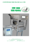
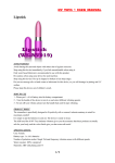
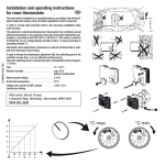
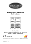
COTSWOLD MECHANICAL LTD CMW 7000 USER MANUAL CMW7000 User Manual 1. COTSWOLD MECHANICAL LTD Contents Page Number: Title & Description: 1. 2. 3. Front Cover Contents Basic Overview 5. 7. 11. 12. 14. 16. 18. 19. 20. 21. 22. 79. 84. 86. 89. 91. 93. 98. Hints on Successful Operation Machine Overview Product Feed Hopper Vibratory Feed System Gating System Hopper Probe Assembly Loadcell Mechanism Settling Plate Assembly Box Detect Assembly Box Clamp Assembly CMW Controls Variable Frequency Vibrator Option Data Recorder Option Cleaning Maintenance Pneumatics Drawings Electronics CMW7000 User Manual 2. COTSWOLD MECHANICAL LTD Basic Overview The CMW range of weighing machines have the same basic mode of operation and whilst the format, style, size and specification may differ to suit different products, weights and speed requirements basic principles are valid throughout. 1) Product is placed into a holding hopper and is then fed automatically, at a fast speed, into a box or carton that ‘sits’ on a weighing mechanism. When the target weight is almost reached, the feed rate of product slows to a trickle. On achieving the required weight, product feed stops altogether and, after checking that the weight is correct, the weighed product and container are released and exit the machine via a section of powered roller conveyor. 2) The product infeed hopper normally has adjustable gates to regulate the depth of product allowed out on to the feed system 3) The feed system normally comprises a series of vibratory feeders (sometimes referred to as feed trays) 4) With a standard CMW7000 Machine there is only one feed tray. This tray takes product out of the hopper under strict control into the gating system. The feed tray on a CMW7000 Machine performs both the ‘bulk’ and ‘fine’ filling function. 5) At the outfeed end of the feed system there are normally some “gates”. These are designed to assist in the precise feed of the product. In the case of the bulk gate, this closes to prevent the majority, or bulk of the product on the feed tray entering the carton or box whilst ‘fine’ feed is taking place. Similarly, the fine feed gate closes when the correct weight is in the box or carton making sure that no further product is allowed into the container thus minimizing the possibility of over-weights being produced. 6) The type and design of feed system is determined by the characteristics of the product to be handled. 7) The correct weighing of product relies on a box style container being present at the fill position of the machine. The CMW7000 system usually comprises a 4.0m length of powered roller track conveyor, although the length of which may vary depending on the machine configuration. This section of conveyor carries empty boxes in a controlled manner to the loadcell mechanism located at the fill point. The empty box is weighed, and the machine performs an auto-tare. Effectively, the box is now weightless and the filling with product now commences. Once the correct target weight is achieved, the box exits the machine, again via the remaining section of roller track conveyor. Depending upon how the machine is configured, a settling function can be performed. This is usually optional, and involves the box being gently shaken pneumatically, to ensure that the box lids can be closed correctly. CMW7000 User Manual 3. COTSWOLD MECHANICAL LTD Basic Overview (continued) 8) The weighing function of the machine is performed by a precision weighing mechanism (normally a loadcell) 9) The gating system is located above a chute that transfers the product into the box to be filled. These outlet chutes are designed to suit the application and may be fitted with different size and style of extensions to adapt them to various sizes and styles of packaging. 10) All aspects of the machine operation including, target, bulk and fine weights, the speed (amplitude) of the vibratory feeders, the frequency of the auto-tare facility, the amount of time the box remains in the fill position etc. are all set and held in the “Product Code Memory” of the control system - along with all other information necessary for the correct operation of the machine. 11) Once the correct settings for a particular product and weight combination have been determined they can be retained in the control system memory and simply recalled the next time they are required to be used. 12) CMW7000 User Manual 4. COTSWOLD MECHANICAL LTD Hints on successful operation THE SECRET OF ACCURATE AUTOMATIC WEIGHING IS IN OBTAINING A CORRECT AND RELIABLE PRODUCT FEED INTO THE BOX OR CONTAINER. 1) The amount of product on the bulk (primary) tray is determined by: i) The position of the adjustable sliding gate on the front of the hopper. The correct position of this gate is determined by: a) The type of product being handled b) The throughput and depth of product deemed necessary 2) The level of product on the fine (secondary) tray is determined by: i) The position of the adjustable sliding gate on the front of the hopper. The correct position of this gate is determined by: a) The type of product being handled b) The throughput and depth of product deemed necessary IT IS ESSENTIAL TO HAVE A SMALL - BUT SUFFICIENT – FINE FEED. 3) If there is none, or it is too little, invariably over-weights will be produced. i) If it is too long product may build up behind the bulk gate resulting in erratic weights (correct weight followed by an overweight etc.) FINE FEED TOO SHORT - DECREASE the BULK WEIGHT SETPOINT FINE FEED TOO LONG - INCREASE the BULK WEIGHT SETPOINT 4) It is important that the depth and speed of movement of the product are in keeping with the weight being made and the accuracy required. In general the higher the target weight and the smaller the product piece size the greater the depth of product and the faster the movement can be. It is impossible to give exact advice on actual settings, they will only be determined by running the actual product through the machine and by using trial and error along with experience gained in the best method of operation for your own particular products and requirements. CMW7000 User Manual 5. COTSWOLD MECHANICAL LTD Hints on successful operation (continued) Hints on successful operation (continued) Before starting the machine: Set the desired Target weight (Example 10,000g) Set the Fine set point to equal the Target Weight (Example 10,000g) Set the Bulk set point to Target Weight minus 10% (Example 9,000g) Set the vibrator fast speed to 50% and the slow speed to 40% Switch the machine in to run mode. Place a small amount of product in to the vibrator tray; check the product is transferred along the vibrator with a smooth and consistent flow rate. If the transfer of product is too slow or too fast adjust the vibrator fast and slow speeds accordingly. Stop the machine Close the hopper slide gate, and then fill the hopper with product. Now open the hopper slide gate, only a sufficient amount to allow the product to flow from the gate. Re-start the machine. CMW7000 User Manual 6. COTSWOLD MECHANICAL LTD Machine Overview – 1. Vibratory Feed System (See page 12 .) CMW Controls (See page 22.) Product Feed Hopper (See page 11.) Gating Assembly (See page 14) CMW7000 User Manual 7. COTSWOLD MECHANICAL LTD Machine Overview – 2. Hopper Probe Assembly (See page 16.) Loadcell Plate Assembly (See page 18.) Box Clamp Assembly (x1) (See page 21.) Electrical Cabinet Box Detect Assembly (See page 20.) CMW7000 User Manual 8. COTSWOLD MECHANICAL LTD Machine Overview – 3. Pneumatic Cabinet Settling Plate Assembly (See page 19.) CMW7000 User Manual 9. COTSWOLD MECHANICAL LTD Machine Overview – 4. Description: A single lane automatic linear weighing machine which utilises the highest quality components and materials and combines a precision loadcell weighing mechanism with the latest electronic technology. Weight Range: 5kg upto 50kg, although versions may vary. For a typical application, 7kg of twist wrapped chocolate confectionary. Capacity: A wide range of pre-formed cartons or containers can be handled on the CMW7000 system. On a single machine, a range of sizes can also be handled, (within agreed limits) changeover being simply accomplished by the adjustment of guides and the exchange of some chutes. Function: The machine utilises a hopper system that is filled with the product to be weighed. By means of a vibrating tray, product is fed in a controlled manner through the pneumatic gate assemblies. The gating assembly ensures that an empty box or carton is filled to its correct target weight with no excess product overspill. The product weights are continuously monitored by the CMW controls, and once the target weight has been achieved, the now full box exits the machine in a controlled manner by means of a length of powered roller conveyor. Similarly, empty boxes enter the machine via the same length of conveyor where they are ‘indexed’ to the fill position of the machine. As the product exits the gating system, it falls down a chute that is usually custom made to suit individual applications and boxes. This ensures that the product falls into the empty waiting box, the weight of which is continually monitored by the CMW controls. Only when the correct weight of product has been achieved, will the box be released from the fill position and exit the machine. Machine Overview: The CMW7000 System comprises of the following sub-assemblies: 1. Product Feed Hopper 2. Vibratory Feed System 3. Gating Assembly 4. Hopper Probe (optional extra) 5. Load-cell Mechanism 6. Settling Assembly (optional extra) 7. Box Detect Assembly 8. Box Clamp Assembly 9. CMW Controls CMW7000 User Manual 10. COTSWOLD MECHANICAL LTD Product Feed Hopper. Hopper Feed Control Bulk Gate Product Feed Hopper Hopper Gate Adjusting Hand wheel Note: As an optional extra, the Hopper can be fitted with various sound deadening panels to dampen product noise when entering the hopper. These panels are permanently adhered and sealed to the Hopper. Under no circumstances should they be removed. The Product Hopper is usually custom designed to suit the individual product requirements. It is normally mounted by means of quick release over-centre catches. The hopper sits on the top face of the machine frame and is then firmly latched into position. This enables fast removal of the Hopper for cleaning. Product feed from the hopper is controlled via a hopper feed control gate. The volume and depth of product that exits the hopper can be adjusted by loosening the hand-wheel then raising or lowering the hopper slide gate and re-tightening the hand-wheel once the correct level has been achieved. Normally this is set to the minimum gap that will allow the product to flow freely from the hopper. CMW7000 User Manual 11. COTSWOLD MECHANICAL LTD Vibratory Feed System. Bulk / Primary Feed Tray V2 Electro-Magnetic Vibratory Feed Unit The Vibratory Feed system: The CMW7000 system comprises a single vibratory feed tray mounted on an electromagnetic vibratory feed unit. The Primary (Bulk) Vibrator Tray feeds product from the hopper in to the Gating System. When the box is being filled, the tray feeds product at maximum product throughput into the box. As the box approaches target weight, the Bulk Tray switches to a lower speed to dribble feed the last few pieces of remaining product. The exact point of shut-off can be adjusted and set within the CMW controls parameters and is dependent on product flow characteristics. Air Blowers: (Optional Extra) The purpose of the Air Blowers is to maintain a steady stream of cool, dry, non-lubricated air over the electrical coils of the V2 vibratory feed unit. This ensures that there is no build up of heat from the coils that might transfer through the feed tray and melt the product as it feeds through the system. Vibrator Tray Mounting Latches: These allow fast removal of the vibrator tray for cleaning. Tension on the latches is factory set and should require no adjustment. CMW7000 User Manual 12. COTSWOLD MECHANICAL LTD Vibratory Feed System. (Continued.) Method Of Adjustment: (See CMW Instruction Manual, Product Feed Section 3.4 ) The Bulk Vibrator has two speed settings, fast and Slow speed. Each speed is digitally set within the Product Code Menu, values 0-100% Fast Speed: This speed settings is used when feeding the majority (Bulk) of the product through the feed system and in to the Weighing system. The Fast Speeds continue to be used until the “Bulk” set point is achieved. Slow Speed: This speed settings is used to when feeding the final (Fine) or top up of the product to achieve the desired target weight. The Slow Speeds continue to be used until the “Fine” set point is achieved. The “Fine” set point is normally set to slightly below the desired target weight, this allows for product in flight. If the “Fine” set point value is set low the system will stop early and the target weight will not be achieved. The feed system will then begin to top up, again using the slow speed settings. CMW7000 User Manual 13. COTSWOLD MECHANICAL LTD The Gating Assembly Pneumatic Rotary Actuator Fine Gate Air Supply in/out Bulk Gate Bulk / Fine Trap Body The Gating Assembly: This Consists of pneumatically operated Bulk and Fine gates. They are located above the Outlet Chute Assembly. The gates open at the start of the weighing cycle. The Bulk gate closes when the Bulk set point is reached, the product continues to feed at slow speed until the fine set point is reached, at which point the Fine gate closes. If the weight of product in the box / carton is less than the target (minimum weight system) or less than the under weight tolerance (Average weight system), then the fine gate will re-open and the product feed will resume (at slow speed) until the target weight is achieved. The Gating system is Factory set and will not normally require any adjustments. The entire Gating Assembly is located on the front of the machine main frame by means of two key-hole style slots. The unit can easily be removed from the machine frame by releasing the over centre style latch on the top of the unit and lifting the complete assembly clear. IMPORTANT: The air supply must first be switched off and the air supply pipes to the pneumatic rotary actuators disconnected by a suitably qualified person. ADJUSTING SCREW LOCKING SCREW AIR ‘IN’ QUICK RELEASE COLLAR The illustration immediately left shows a typical speed controller as found on the underside of the rotary actuators. By winding the adjustment screw in or out will accelerate or decelerate the speed at which the gates open and close. It is important to tighten the locking screw once the correct position of the adjusting screw has been ascertained. To remove the air pipe from the speed controller, first depress the quick release collar, and then pull the pipe free (disconnect air supply first). CMW7000 User Manual 14. COTSWOLD MECHANICAL LTD The Gating Assembly Fig. 2 Fig. 1 In order to remove the gating assembly (Fig. 1) for cleaning, it is necessary to disconnect the four air supply pipes and un-clip the assembly. The mechanism can then be lifted clear of the two key hole style slots that locate it to the machine frame. The four air supply pipes are un-coupled via a quick release fitting in the side of the machine frame. Fig. 2 shows how the two halves of the fitting can be compressed and then carefully pulled apart. To reengage, the air pipe fitting is simply pushed back into the quick release fitting. Fig. 3 shows how the quick release, over centre latch is released by rotating it in the direction indicated. To re-fasten, the latch should be re-engaged with the hook style keeper and snapped back into its original position. Fig. 3 CMW7000 User Manual 15. COTSWOLD MECHANICAL LTD The Hopper Probe Assembly (Optional Extra) Hopper Probe Adjustable Mountings Hopper Probe Post Hopper Probe The Hopper Probe Assembly: (Optional Extra) The Hopper Probe Assembly is located towards the rear of the machine frame. The actual Hopper Probe itself is sited such that it ‘looks’ downwards into the Hopper. Its purpose is to control the level of product within the machine Hopper. The Hopper Probe monitors the high and low level of product in the hopper. If the product level exceeds the levels to which it has been set, the in-feed equipment (Elevator / Screw Feeder / Conveyor) to the hopper is switched off. The hopper probes have adjustable mountings allowing them to be moved in order to obtain a correct product level reading. Internally the hopper probes have the following features: Normally open & normally closed relay contacts Light on / dark on switching Adjustable sensing range Selectable timing functions, timing off, on delay, off delay, on & off delays selectable timing ranges. CMW7000 User Manual 16. COTSWOLD MECHANICAL LTD Removal of the Hopper Probe Lid & adjustment of the Probe should only be carried out by a suitably qualified electrician, as up to 240v A.C power, in some instances, can be present. CMW7000 User Manual 17. COTSWOLD MECHANICAL LTD The Load-cell Mechanism Box Guide Rails (x2) Guide Rail Clamps (x4) Box Stop Adapter (x1) Box Lift Adapter (x3) Box Stop Cylinder (x1) Loadcell (x1) Box Lift Cylinder (x3) Loadcell Mtg. Plate (x1) The Load-cell Mechanism: Located beneath the section of powered line shaft conveyor is the load-cell mechanism. It is mounted on a plate and it carries a series of pneumatic cylinders and guide rails. Essentially, every time an empty box passes into the fill position, the box stop cylinder stops it. Once the box is in position, it is lifted clear of the roller track by the three box lift cylinders. This enables the load-cell to perform an auto-tare; effectively weighing the box and then zeroing the weight. The Load-cell can then generate the appropriate weight signals for the machine controls as product enters the box. The Load-cell is a precision electronic instrument and is partially protected by an overload stop; this helps to avoid accidental damage due to excessive loading. The overload system will not protect against shock loading, therefore the Load-cell unit should be treated with extreme care. Boxes should always be removed when moving the machine. No user adjustments are required for the Load-cell Mechanism. For information on calibration of the loadcell, see page 37. CMW7000 User Manual 18. COTSWOLD MECHANICAL LTD The Settling Plate Assembly (Optional Extra) Box Lift Adapter (x3) Box Stop Adapter (x1) Cylinder Mtg. Plate (x1) Box Stop Cylinder (x1) Anti-Vibration Mounts (x4) Box Lift Cylinder (x3) The Settling Plate Assembly (optional extra): The Settling plate assembly is located beneath the powered roller conveyor in the area where the filled boxes exit the machine. As its name suggests, the settling assemblies purpose is to pneumatically agitate the filled boxes so that the product does not ‘mound’ in the middle. Failure to settle the boxes can result in the box lids not closing properly. As a full box enters the settling station, the box stop cylinder halts it in position. The box lift cylinders then ‘shake’ the box by extending & retracting rapidly for a short period of time. All the Box Lift Adapters and Box Stop Adapters are of open construction so that any spilt product can easily be removed. The Settling Plate Assembly is located by four anti-vibration mounts to prevent vibration being transmitted back through the machine frame and into the load-cell. CMW7000 User Manual 19. COTSWOLD MECHANICAL LTD Box Detect Assembly Box Detect Cover (x1) Box Detect Mount (x1) Probe (x1) Bin No. A030 Mounting Bracket (x1) The Box Detect Assembly: Located at various points along the edge of the line shaft conveyor, are a series of box detect assemblies. Their purpose is to provide vital feed back to the Programmable Logic Controller on the presence or non-presence of boxes at crucial points of the box journey along the line shaft conveyor. The sensor is a diffuse reflective type with an M18 style body. They are factory set and should not require further attention. CMW7000 User Manual 20. COTSWOLD MECHANICAL LTD Box Clamp Assembly Box Clamp Cover (x1) Clamp Cylinder Mount (x1) Box Clamp Mount (x1) Box Clamp Cylinder B024 (x1) Box Gripper (x1) The Box Clamp Assembly: The Box Clamp Assembly is located on the rear of the line shaft conveyor, just prior to the box fill position. As empty boxes stack up prior to being filled, the box gripper actuates, holding the second box to be filled firmly in position against the guide rail. This means that when the first box moves into the fill position, the other remaining boxes stay in the waiting position and do not enter the fill position as well. There is no speed control on the clamp cylinder – its position is factory set and should not require further attention. CMW7000 User Manual 21. COTSWOLD MECHANICAL LTD CMW CONTROLS USER MANUAL CMW7000 User Manual 22. COTSWOLD MECHANICAL LTD CONTENTS ............................................................................................... 1. INTRODUCTION .................................................................................. 2. OPERATION ........................................................................................ 2.1 USER INTERFACE...................................................................... 2.2 SECURITY................................................................................... 2.3 HOME SCREEN .......................................................................... 2.4 SETTLED WEIGHTS SCREEN ................................................... 2.5 STATISTICS SCREENS .............................................................. 2.6 MAIN MENU ................................................................................ 2.7 PRODUCT LIBRARY ................................................................... 2.8 STATIC CALIBRATION ............................................................... 2.9 MANUAL ZERO ........................................................................... 2.10 EMPTY MACHINE ....................................................................... 2.11 DIAGNOSTICS ............................................................................ 3. PRODUCT PARAMETERS .................................................................. 3.1 3.2 PRODUCT WEIGHTS ................................................................. 3.1.1 FEED BY WEIGHT ........................................................ 3.1.2 FEED BY COUNT ......................................................... PRODUCT OPTIONS 1 ............................................................... CMW7000 User Manual 23. COTSWOLD MECHANICAL LTD CONTENTS 3.3 PRODUCT OPTIONS 2 ............................................................... 3.4 PRODUCT FEED ........................................................................ 4. MACHINE CONFIGURATION.............................................................. 4.1 INPUT CONFIGURATION ........................................................... 4.2 OUTPUT CONFIGURATION ....................................................... 4.3 WEIGHING CONFIGURATION ................................................... 4.3.1 WEIGHING UNITS ........................................................ 4.3.2 WEIGHING SETTLE ..................................................... 4.3.3 WEIGHING OPTIONS ................................................... 4.3.4 WEIGHING BAGMAKER ............................................... 4.3.5 WEIGHING VIBRATOR FACTORS ............................... 4.4 SHIFT / BATCH CONFIGURATION ............................................ 4.5 SERIAL COMMUNICATIONS SETUP ......................................... 4.6 SETUP TIME / DATE ................................................................... 4.7 MACHINE CONFIGURATION ..................................................... 4.7.1 MACHINE SINGLE / TWIN ............................................ 4.7.2 MACHINE VIBRATOR CONFIGURATION .................... 4.7.3 MACHINE DISCHARGE CONFIGURATION ................. 4.7.4 MACHINE USER LANGUAGE ...................................... CMW7000 User Manual 24. COTSWOLD MECHANICAL LTD CONTENTS 4.7.5 MACHINE PASSWORD SETUP ................................... 5. TESTING THE MACHINE .................................................................... 5.1 INPUT TEST ................................................................................ 5.2 OUTPUT TEST ............................................................................ 5.3 VIBRATOR TEST ........................................................................ 5.4 STATIC WEIGHING INFO . ......................................................... 5.5 DYNAMIC WEIGHING TRACE.................................................... CMW7000 User Manual 25. COTSWOLD MECHANICAL LTD 1.0 INTRODUCTION This manual has been compiled to assist the machinery manufacturer in the basic operation of the CMW Control System . The controller utilises a backlit high contrast LCD display and operator keypad to enable the display and modification of all areas of the linear weigher operation. The weighing characteristics of up to 100 different products can be pre-set into the product library and then products may be called up for use by either their name or optional product code. The unit is easily cleaned, being housed with a stainless steel enclosure, sealed to the IP65 standard. The controller can be configured to control one or two weighers and up to four vibrators. Depending upon the configuration of your machine, not all options shown in this manual may be accessible or appear on the screen layouts. CMW7000 User Manual 26. COTSWOLD MECHANICAL LTD 2.0 OPERATION In this part you will be guided through the operation of the basic functions of the controller. This manual assumes that the machine is correctly installed and powered on. Below is a summary of the following sections in this part. Section 0 is a guide to the user interface. Section 0 shows the security features for protecting data entry. Section 0 shows the layout of the normal operating home display screen. Section 0 explains the settled weights screen. Section 0 explains the statistics screens. Section 0 shows the main menu screen. Section 0 is a detailed guide to the product library. Section 0 explains how to statically calibrate the weigher. Section 0 explains how to manually zero the weigher. Section 0 explains how to empty the weigher. Section 0 explains the diagnostic fault reporting. CMW7000 User Manual 27. COTSWOLD MECHANICAL LTD 2.1 USER INTERFACE The user interface is designed to allow simple set-up of the linear weigher and display clear weighing and statistical information during operation. Numerical data is entered via the 0-9 and ‘.’ keys with the data being accepted with the ENTER key. These same keys can also be use to enter alphanumeric characters in a similar fashion to that of a mobile phone. The four ARROW keys are used to select specific screen entries and to move around the screens quickly. The four keys at the bottom right hand side of the keypad are used for the machine operation. Each of these keys contains a red LED lamp to indicate when they are active. Directly below the LCD screen are six keys whose functions depend upon the screen displayed. The bottom of the screen contains a row of display icons that indicate the function of each key. See Button Table for meanings. CMW7000 User Manual 28. COTSWOLD MECHANICAL LTD BUTTON TABLE Go to main menu. Go to configuration menu. Go to test menu Return to home screen. Main operating screen. Return to previous screen from home screen. Show statistics screens. Show batch statistics Show shift statistics Show histogram to +/- T1 limits. Show histogram to _/- T2 limits Show settled weights screen. Shows weighing status. Go to monitor screen. CMW7000 User Manual 29. COTSWOLD MECHANICAL LTD BUTTON TABLE Go to previous screen. Go to next screen. Select product to run, change product. Edit current product. Accept. Cancel. Copy item to another location. Delete selected product. Change entry font to lower case. Change entry font to upper case. Run / Enable Stop / Disable CMW7000 User Manual 30. COTSWOLD MECHANICAL LTD BUTTON TABLE Start next calibration stage. Run To empty. Empty. Reset data. Test output on / off. Cycle selected test output. CMW7000 User Manual 31. COTSWOLD MECHANICAL LTD 2.2 SECURITY Data within the controller is protected from unauthorised access by means of three levels of password :1. Supervisor (lowest) 2. Engineer 3. Manufacturer (highest) When access code is required the screen above will pop up. At this point the user should enter their 4-digit code followed by ‘ENTER’. CMW7000 User Manual 32. COTSWOLD MECHANICAL LTD 2.3 HOME SCREEN Last Discharged Weight for Weigher Live Weights Bulk Feed Fine Feed Weight Complete Main operating screen shows status for one or two weighers. CMW7000 User Manual 33. COTSWOLD MECHANICAL LTD 2.4 SETTLED WEIGHTS SCREEN Press / to ENABLE / DISABLE the weighing stations. Shows the live weight against the settled weight for each weigher such that when weighing is complete this will provide an indication of how accurate the weighing settle parameters are. CMW7000 User Manual 34. COTSWOLD MECHANICAL LTD 2.5 STATISTICS SCREENS Shows weights, occurrences and standard deviation for batch and shift statistics. Use batch/shift button to move between the two statistics sets. See section 0 SHIFT / BATCH CONFIGURATION to set up batch statistics over time or number of weighings and shift statistics for one to three shifts. CMW7000 User Manual 35. COTSWOLD MECHANICAL LTD Shows weight histogram for batch or shift. Use batch/shift button to move between the two statistic sets. Use T1/T2 button to select histogram spread displayed. 2.6 MAIN MENU Main menu allows entry into the main control topics. Configuration Menu access set up overall machine operation Test Menu access test functions of the machine Static Calibration calibration section Manual Zero manual zero Empty Machine to run the machine until empty Service Info. Service contact details, program monitoring Password enable/disable current password Data within the controller is protected from unauthorised access by means of three levels of password. CMW7000 User Manual 36. COTSWOLD MECHANICAL LTD 2.7 PRODUCT LIBRARY The machine allows the details for up to 100 different products to be held in non-volatile memory. Use UP / DOWN ARROWS to select current product to run or edit. Confirm selection with OK button. Use COPY button to copy selected product to a new location. This is also used to create a new product. Use DELETE button to delete the currently selected product. CMW7000 User Manual 37. COTSWOLD MECHANICAL LTD 2.8 STATIC CALIBRATION 1. Before commencing for multi-weigher machines select the weigher to calibrate with the ENTER key. The Calibration Counter displayed on this first screen is a non-resettable counter that increments after each successful calibration. It is a weights and measures requirement to ensure no unauthorised calibrations can be performed. 2. Ensure weigher is warmed up; allow at least 15 minutes for this. 3. Ensure the weigher is empty and clean of product. 4. Press to begin calibration. Next screen is displayed. Follow screen instructions until successful calibration. CMW7000 User Manual 38. COTSWOLD MECHANICAL LTD STATIC CALIBRATION CONTINUED CMW7000 User Manual 39. COTSWOLD MECHANICAL LTD STATIC CALIBRATION CONTINUED 5. Place calibration weight value as shown on the weigher and follow screen instructions. CMW7000 User Manual 40. COTSWOLD MECHANICAL LTD STATIC CALIBRATION CONTINUED CMW7000 User Manual 41. COTSWOLD MECHANICAL LTD STATIC CALIBRATION CONTINUED 6. Check successful calibration by displayed weight agreeing with actual weight on weigher. CMW7000 User Manual 42. COTSWOLD MECHANICAL LTD 2.9 MANUAL ZERO Before commencing for multi-weigher machines select the weigher to manually zero with the ENTER key. Ensure the weigher is empty and clean of product. Follow screen instructions. CMW7000 User Manual 43. COTSWOLD MECHANICAL LTD MANUAL ZERO CONTINUED CMW7000 User Manual 44. COTSWOLD MECHANICAL LTD Return to main menu. 2.10 EMPTY MACHINE To empty the machine of residual product. Before commencing for multi-weigher machines select the weigher to empty with the ENTER key. Press is ignored. to run normally until no product left in the machine. Low product probe Press open. to empty the machine. Runs vibrators at fast speed with all the doors CMW7000 User Manual 45. COTSWOLD MECHANICAL LTD 2.11 DIAGNOSTICS When any machine faults exist, the red lamp in the ‘?’ key [HELP] flashes. Pressing the ‘?’ will list the current diagnostic faults (press again to return to previous screen). The diagnostic types are either general or weigher specific. Weigher specific diagnostic include the weigher number as an icon within the message. The possible diagnostics are listed below together with a brief explanation of their meaning. CMW7000 User Manual 46. COTSWOLD MECHANICAL LTD GENERAL 1. "Memory Loss" The program memory has been corrupted. Either the battery is switched off or exhausted or there is a program fault. 2. "Reset DIL On" The reset DIL switch has been left on and should be switched off. This is DIL switch 4. With this switch on the program memory is cleared to all zeros at power on. 3. "Invalid System Parameters" There are inconsistencies within the machine configuration settings. a. Incorrect Checksum of Data b. Maximum In-Flight Adjustment > 75% 4. "Invalid System Shift Times" There are inconsistencies within the shift times settings. a. End of Shift Times must be in ascending order. DIAGNOSTICS CONTINUED 5. "Invalid System Refill Control" There are inconsistencies within the refill control settings. a. If ‘infeed’ output is selected then ‘full hopper’ input must be selected b. and if Refill is controlled by Low Hopper condition then a ‘low hopper’ input must be selected. 6. "Invalid Product Parameters" The current product code settings are incorrect. a. Incorrect Checksum of Data b. Invalid Product Weights 7. "Invalid Product Weight(s)" The current product code weights settings are incorrect. a. Target Weight < Underweight b. Target Weight > Overweight CMW7000 User Manual 47. COTSWOLD MECHANICAL LTD 8. "Printer Busy" The printer buffer is full up and further printouts cannot be done until it has emptied. 9. "Emptying" Machine emptying is in progress. 10. "Refilling Hopper" Hopper refilling is in progress. 11. "Hopper Low in Product" The ‘hopper low level’ input indicates low product and the vibrators are disabled. 12. "Re-Sample Required" No Piece Weight Sample information exists for the current product. Perform a Piece Weight Sample procedure or enter a new Item Weight within the product code. DIAGNOSTICS CONTINUED 13. "Vibrators Disabled" There is no Mains Power supplied to the vibrator drive card or it is disconnected. 14. "Warm Up Period" The machine has just been switched on and is warming up. Weighing may be slightly inaccurate during this period. 15. "Emergency Stop Input" The ‘emergency stop’ input is ON. 16. "Line Stop Input" The ‘line stop’ input is ON. 17. "Warning - Low Air Pressure" The ‘low air pressure’ input is ON. CMW7000 User Manual 48. COTSWOLD MECHANICAL LTD 18. "Low Air Pressure Timed Out" The ‘low air pressure’ input has been ON for a maximum time and the machine is stopped. 19. "Warning - Demo Mode Operation" The demonstration mode has been selected. The machine cannot run in this mode. WEIGHER DIAGNOSTICS 1. Loadcell Not Communicating" The loadcell amplifier is not working or disconnected. 2. Re-Calibration Required" The operator has changed important weighing parameter(s) or the weighing information is corrupt. 3. "Weigher At Lower Limit" The weighing analogue to digital converter is giving its minimum output. 4. "Weigher At Upper Limit" The weighing analogue to digital converter is giving its maximum output. 5. “Zero Weight too Low" During the zero phase of the static calibration routine, the analogue to digital converter output is below a sensible minimum value. Check loadcell and LDU connections. CMW7000 User Manual 49. COTSWOLD MECHANICAL LTD 6. "Zero Weight too High" During the zero phase of the static calibration routine, the analogue to digital converter output is above a sensible maximum value. Check loadcell and LDU connections. 7. "Calibration Span too Low" For an Approved machine the span of the calibration weight must be above a certain percentage of the loadcell output. 8. “Calibration Weight too Low" The chosen calibration weight is too small for the size of loadcell. 9. "Calibration Weight too High" The chosen calibration weight is too large for the size of loadcell 10. "Invalid Weight Resolution" For an Approved machine the selected resolution is invalid for the calibration. 11. "Unable to Settle" During the weighing operation settling period, the a/d output was not stable within the set parameters. Check weighing parameters in machine configuration WEIGHER DIAGNOSTICS CONTINUED 12. "Unable to Tare" During the weighing cycle tare the weigher was unable to achieve a settled zero level within the time allocated. 13. "Tare Weight too Low" During the weighing cycle tare the tare weight level was below the zero calibration level. Check weigher with test weights to ensure it is operating correctly. 14. "Tare Weight too High" During the weighing cycle tare weight was so high that the target weight is not achievable within the range of the machine. Check weigher with test weights to ensure it is operating correctly. 15. "Zero Span Exceeded" For an Approved machine only, during a manual zero operation the zero level has drifted more than 4% of the range since the last static calibration. CMW7000 User Manual 50. COTSWOLD MECHANICAL LTD 16. "Weigher Disabled" The weigher has been disabled from the front panel. 17. "Feed Disabled" The ‘feed enable’ input is OFF. 18. "Weigher Not Feeding" The ‘feed fault’ input was detected during a weighing cycle. 19. "Weighpan Open" The ‘weighpan open’ input is ON and the weighing cycle is aborted. 20. "Weight Not Removed" A new ‘discharge call’ input is received before the last weight has been removed. This only applies to machines, which do not have a weighpan. 21. "Low in Product" The ‘low hopper’ input for the given weigher indicates low product and the vibrators are disabled. 3.0 PRODUCT PARAMETERS 3.1.1 PRODUCT WEIGHT Product Name: Enter up to 20 characters to describe the current product. Use the upper/lower case button CMW7000 User Manual 51. COTSWOLD MECHANICAL LTD to change between capital and miniscule letters and the ‘0’ to ‘9’ keys to enter alphanumeric characters. The space character is located on the ‘0’ key and the ‘CANCEL’ key may be used to correct mistakes. Average/Minimum Weight Mode: Use the ENTER key to toggle between the two modes of weighing operation. Target: Product target weight Overweight: Weight before which the weighing is to be rejected as overweight. Underweight: Weight before which the weighing is to be rejected as underweight in an AWS system. Note: Overweight >= Target >= Underweight. 3.2 PRODUCT OPTIONS 1 Autotare Use the ENTER key to toggle between the tare modes. CMW7000 User Manual 52. COTSWOLD MECHANICAL LTD OFF autotare is not enabled EVERY CYCLE The weighpan is tared at the beginning of every weigh cycle. TIMED The autotare is performed on a timed basis. (See next parameter.) Tare Interval range 0 – 20 minutes Frequency at which autotare is performed. Topup Turn topup operation ON/OFF. When topup is turned ON: In Average Weight Mode if during the time that the weight is settling after feed, the settled weight falls below the Underweight then the feed is restarted in an attempt to achieve the minimum target weight. In Minimum Weight Mode if during the time that the weight is settling after feed, the settled weight falls below the Target weight then the feed is restarted in an attempt to achieve the minimum target weight. Feed will run up to the Maximum Topup Time. (see next page) 3.2.1 PRODUCT OPTIONS 1 CONTINUED Maximum Topup Time range 0.00 – 5.00 seconds The maximum time allowed for an individual topup. A time of zero limits topup only to the threshold weight. In-Flight Correction Turn In-Flight Correction operation ON/OFF. If the In-Flight Correction is turned ON: In Average Weight Mode an error correction weight is calculated as 50% of the difference of the average weight collected over the Sample Size batch and the Target Weight. If the average weight is below the Target Weight then the Bulk and Fine Cut-off weights are moved up by the error correction weight. If the average weight is below then the Bulk and Fine Cut-off weights are moved down. In Minimum Weight Mode an error correction weight is calculated as 50% of the difference CMW7000 User Manual 53. COTSWOLD MECHANICAL LTD of the minimum weight collected over the Sample Size batch and the Target Weight. If the minimum weight is below the Target Weight then the Bulk and Fine Cut-off weights are moved up by the error correction weight. If the minimum weight is below then the Bulk and Fine Cut-off weights are moved down. This operation attempts to correct for any product falling (In-Flight) from the vibrator feeders after the feed has stopped Sample Size range 1 - 100 Number of discharges over which the in-flight correction calculations are performed. 3.3 PRODUCT OPTIONS 2 Drops Per Bag range 1 – 100 Enter the number of discharges required to fill a bag. CMW7000 User Manual 54. COTSWOLD MECHANICAL LTD Weighpan Open Time range 0.00 – 5.00 seconds Time for which weighpan remains open during product discharge upon completion of a weighing. Weighpan Close Time range 0.00 – 5.00 seconds Time after starting to close the weighpan when the next feed cycle commences. Time is to allow the weighpan doors to completely close before restarting feed. Rear Probe Enabled Use the ENTER key to select when the rear probe is enabled Hopper Low CMW7000 User Manual 55. COTSWOLD MECHANICAL LTD Start & Stop delays only if LOW LEVEL PROBE FITTED Timer Function Length (Duration of Function Output) Example Use, Product Settling Duration Time 3.4 PRODUCT FEED CMW7000 User Manual 56. COTSWOLD MECHANICAL LTD Vibrator Speeds range 0.0% - 100.0% Enter the fast and slow vibrator amplitudes for controlling the feed rate of the current product. Bulk Cut-off Weight range 0 – target weight Enter the weight at which the vibrators will switch from fast to slow feeding. Fine Cut-off Weight range 0 – target weight Enter the weight at which the vibrators will stop feeding and the weigher start to settle. Use the COPY button to copy the entered settings to all weighers. If Accelerometers Are Enabled This button memorises the current vibrator amplitude 4. MACHINE CONFIGURATION CMW7000 User Manual 57. COTSWOLD MECHANICAL LTD The detailed setup of the machine is done from these screens. Usually this is only done when the machine is first installed. 4.1 INPUT CONFIGURATION CMW7000 User Manual 58. COTSWOLD MECHANICAL LTD This screen allows each digital logical input to be assigned to a physical input. Use the ENTER key to select the logical input and the UP/DOWN ARROW keys to select the physical input. CMW7000 User Manual 59. COTSWOLD MECHANICAL LTD 4.2 OUTPUT CONFIGURATION This screen allows each digital logical output to be assigned to a physical output. Use the ENTER key to select the logical output and the UP/DOWN ARROW keys to select the physical output. This screen allows the sense of each individual digital output to be inverted. Use the ENTER key to toggle between YES/NO. CMW7000 User Manual 60. COTSWOLD MECHANICAL LTD 4.3 WEIGHING CONFIGURATION 4.3.1 WEIGHING UNITS Display Units Select the weighing units Grams or Kilograms with which the machine will operate. Resolution of Units X / X.X / X.XX / X.XXX Select how the units are to be displayed. Calibration Weight Enter the calibration weight with which the weighers are to be statically calibrated. Calibration Tolerance Enter the calibration tolerance in a/d bits used in determining when the weighing is settled and stable during calibration. CMW7000 User Manual 61. COTSWOLD MECHANICAL LTD 4.3.2 WEIGHING SETTLE Delay Before Settle range 0.00 – 5.00 seconds This time is the delay after the feed has stopped before the program looks for a settled weight. Settle Length range 1 – 126 Enter the number of values which determine the length of the settle buffer. Settle Average Enter the frequency at which values are placed in the settle buffer. The frequency is defined in multiples of 20 milliseconds. Weighing Tolerance range 0 – 1000 Enter the weighing tolerance in a/d bits used in determining when the weighing is settled and stable. Loadcell Filter Type range Off, 7.3 – 1.1 Typical Bessel Select the digital filter Type. Bessel, Butterworth, Fast Bessel or gaussian Loadcell Filter Cutoff range 1 – 14 Typical 1 Enter the required filter setting for the loadcell Digitiser, a higher filter equals less damping and a lower frequency equals heavier damping. CMW7000 User Manual 62. COTSWOLD MECHANICAL LTD 4.3.3 WEIGHING OPTIONS Delay Before Tare range 0.00 – 5.00 seconds This is the time between starting a tare and checking for a settled weight within the calibration tolerance. Maximum Tare Limit range 0 – 100 % Enter maximum tare level as a percentage of the Target Weight. Bulk Hysteresis range 0 – 100 % Enter the bulk hysteresis as a percentage of the bulk weight. If during the fine feed of a weighing cycle the weight falls below this percentage of the bulk weight, the machine will revert to bulk feeding. Maximum In-flight Adjust Enter the maximum in-flight adjustment as a percentage of the target weight. When performing in-flight correction this is the maximum amount the cut-off points will be adjusted by for any one correction. CMW7000 User Manual 63. COTSWOLD MECHANICAL LTD 4.3.4 WEIGHING BAGMAKER Weighpan Fitted Select whether a weighpan is fitted or not. If no weighpan selected the machine will assume it is feeding directly onto a weigh platform. Bagmaker Type Type of bagmaker fitted to the weigher. CYCLIC NON-CYCLIC Delay Before Full Bag range 0.00 – 5.00 seconds Enter the time between discharging the weighpan and issuing the full bag signal. Full Bag Energise Time range 0.00 – 5.00 seconds Pulse time to the bagmaker. CMW7000 User Manual 64. COTSWOLD MECHANICAL LTD 4.3.5 WEIGHING VIBRATOR FACTORS Vibrator Speed Factors This percentage scales the vibrator amplitudes as set in the product code. It is used to balance the vibrator outputs so that they feed at the same rate for the same amplitude. CMW7000 User Manual 65. COTSWOLD MECHANICAL LTD 4.4 SHIFT / BATCH CONFIGURATION No Batch Statistics / Batch By Time / Batch By Quantity Toggle ENTER to select type of batch statistics required. Batch Interval Frequency of batch statistics printout. For Batch By Time, ENTER For Batch By Quantity, ENTER number of drops. Number of Shifts Enter the number of shifts required, followed by their start times as hours:minutes. CMW7000 User Manual 66. COTSWOLD MECHANICAL LTD 4.5 SERIAL COMMUNICATIONS SETUP For each of the serial communications channels shown, setup the following parameters. Baud Rate Press ENTER key until correct baud rate for the device is shown Data Bits Select either 7 or 8 data bits as required by the device. Parity ODD EVEN or NONE. Stop Bits Select 0 or 1. CMW7000 User Manual 67. COTSWOLD MECHANICAL LTD 4.6 SETUP TIME / DATE Setup current time and date. The system clock is battery backed and will maintain the correct time even when the machine is switched off. CMW7000 User Manual 68. COTSWOLD MECHANICAL LTD 4.7 MACHINE CONFIGURATION 4.7.1 MACHINE SINGLE / TWIN 8 Inputs / 16 Inputs Select number of physical inputs fitted to the machine. On simple machines this entry cannot be changed. 8 Outputs / 16 Outputs Select number of physical outputs fitted to the machine. On simple machines this entry cannot be changed. Number of Weighers Toggle ENTER to select between a single or a twin weigher. Count Option Toggle ENTER to ENABLE / DISABLE the count option. CMW7000 User Manual 69. COTSWOLD MECHANICAL LTD 4.7.2 MACHINE VIBRATOR CONFIGURATION Vibrator Configuration Select the allocation of vibrator channels. Select the image to represent the particular layout of the vibrator configuration. CMW7000 User Manual 70. COTSWOLD MECHANICAL LTD 4.7.3 MACHINE DISCHARGE CONFIGURATION Discharge Configuration Select the method of discharge. The weighers can be discharged by a common call input, where the first weigher which was ready is discharged, or each weigher can have an individual call. CMW7000 User Manual 71. COTSWOLD MECHANICAL LTD 4.7.4 MACHINE USER LANGUAGE Printer Choose 40 COLUMN / 80 COLUMN or NO PRINTER. Machine Identity Enter identity name of up to 20 characters. Used on printouts to identify weighing machine. Language Select language for display and printouts. CMW7000 User Manual 72. COTSWOLD MECHANICAL LTD 4.7.4 MACHINE PASSWORD SETUP This screen can only be selected by the current level 4 password holder. Enter or reassign the password level codes. CMW7000 User Manual 73. COTSWOLD MECHANICAL LTD 5.0 TESTING THE MACHINE From the test menu select test area of interest. 5.1 INPUT TEST Circle indicators show state of inputs ON/OFF. CMW7000 User Manual 74. COTSWOLD MECHANICAL LTD 5.2 OUTPUT TEST Use UP/DOWN ARROWS to select output. Select to turn on/off selected output. Select to cycle the selected output. Press / to RUN / STOP the test. CMW7000 User Manual 75. COTSWOLD MECHANICAL LTD 5.3 VIBRATOR TEST Enter test vibrator amplitudes. Press / to RUN / STOP the vibrators. CMW7000 User Manual 76. COTSWOLD MECHANICAL LTD 5.4 STATIC WEIGHING INFO Shows current state of the loadcell a/d output and its conversion into weight. Press to reset the Minimum, Maximum, Variance information. CMW7000 User Manual 77. COTSWOLD MECHANICAL LTD 5.5 DYNAMIC WEIGHING TRACE Setted Weight Feed Time Settle Time C Cycle time Press ENTER to select weigher of interest. Press to reset the weighing trace information. CMW7000 User Manual 78. COTSWOLD MECHANICAL LTD 3.1.2 PRODUCT CODE OPTION FOR COUNTING 3.1.3 FEED BY COUNT 3.1.4 When the Count Option is Enabled (See Section 0 4.7.1 MACHINE SINGLE / TWIN) then the Feed by Count option may be selected within the product setup. The entries below apply to Feed by Count. Item Weight Weight of single item of the pieces to be counted. Target Number of items to be counted as the target. Based upon the Item Weight entered above the weigher calculates a target weight based upon this count. Overweight Number of items to be rejected as overcount. Underweight Number of items to be rejected as undercount. End CMW7000 User Manual 79. COTSWOLD MECHANICAL LTD VARIABLE FREQUENCY VIBRATOR OPTION The variable frequency vibrator option, allows the vibrator control frequency to be adjusted to maximize the vibrator performance. 4. This reduces the need to manually tune vibrators, by replacing springs. 5. There is also an increase in usable life of the springs, by adjusting the control frequency to compensate for spring wear. 6. 7. When variable frequency control boards are fitted: The Machine Configuration Screen (1) will appear as below: External Vibs/Belts will be set to RS485. CMW7000 User Manual 80. COTSWOLD MECHANICAL LTD VARIABLE FREQUENCY VIBRATOR OPTION Setting up Vibrators using frequency control: Go Test Menu (Main Menu Option 2), Vibrator Test (Option 3) Vibrator Test Screen (1): 1. Set the Vibrator 1 amplitude to 80.0 %. 2. Set the Vibrator 2 amplitude to 00.0 % 3. Use to go to Vibrator Test Screen (2) CMW7000 User Manual 81. COTSWOLD MECHANICAL LTD VARIABLE FREQUENCY VIBRATOR OPTION Setting up Vibrators using frequency control: (Continued) Vibrator Test Screen (2) 4. Set Vibrator 1 Frequency to 50.0 hz 5. Use to enable Vibrator Test = Test on 6. Adjust the frequency by 0.1 hz increments / decrements until the required vibrator amplitude is achieved 7. Use to go back to Vibrator Screen (1) CMW7000 User Manual 82. COTSWOLD MECHANICAL LTD VARIABLE FREQUENCY VIBRATOR OPTION Setting up Vibrators using frequency control: (Continued) Vibrator Test Screen (1): 8. Ensure that the vibrator 1 dose not hammer (Noisy) when the amplitude is set to 100.0 %. 9. If hammering occurs, then re-adjust the frequency until hammering stops. 10. When desired settings have been achieved, and then note the Frequency values (ie. 48.6 hz). 11.Repeat the process from step 1, substituting vibrator 1 with the Next vibrator until all Vibrators have been set and their frequency values recorded. Now go to Configuration Menu, Weighing Configuration Screen (6) CMW7000 User Manual 83. COTSWOLD MECHANICAL LTD VARIABLE FREQUENCY VIBRATOR OPTION Saving the frequency Values: Engineer’s level of password is required to enable changes. The following Weighing Configuration screen (6) shows the option for two Vibrators. Enter the recorded frequency values from the previous section The Frequency values are now saved. CMW7000 User Manual 84. COTSWOLD MECHANICAL LTD Optional Data Recorder LINEAR WEIGHER CMW7000 User Manual 85. COTSWOLD MECHANICAL LTD Data Recorder 1. “Active” LED should be on when power applied 2. Insert Compact Flash Card 3. Press “Stop/Record” Button “R” LED Will Light 4. During Recording “D” LED Will Flash 5. To Stop Recoding Press Stop/Record” Button “R” LED Will Go Out 6. Press Card Eject Button To Remove Card 7. Insert Compact Flash Card into the Card Reader & Connect the Card Reader to a PC,The file Type is *.DAT use Notepad to Open. CMW7000 User Manual 86. COTSWOLD MECHANICAL LTD Cleaning Schedule: The weighing system is designed such that most of the component parts that come into contact with the product can easily be removed for cleaning purposes. This includes: Hopper, Feed Trays Weighpan, Rise & Fall Chutes & Outlet Chute. BEFORE REMOVAL OF THESE COMPONENT PARTS CAN COMMENCE, IT IS ESSENTIAL THAT BOTH THE AIR SUPPLY & THE ELECTRICAL SUPPLY TO THE MACHINE BE ISOLATED BY AN APPROPRIATLEY QUALIFIED PERSON. All the contact parts are manufactured from grade 304 or 316 stainless steel and will easily withstand cleaning with most food industry approved sanitary cleaning fluid. It is recommended that the machine is stripped down and cleaned at least once per eight hour shift. It is also essential that cleaning take place when there is a change of product to be run through the machine. During any clean down procedure, it is vital to ensure the cleansing of the entire machine and not just the removable contact parts. The entire range of weighing machines have the same basic mode of operation and whilst the format, style, size and specification may differ to suit different applications, the strip down procedure for cleaning is generally as follows: 1. Release the over centre latches (where fitted) and remove hopper. If latches are not fitted, the hopper is usually cleaned in its normal working position, but can be un-bolted for complete removal. (see Fig. 1 for a typical example of a latch) Fig. 1 2. Release the over centre latches (where fitted) and remove the rear or bulk vibratory feed tray. If latches are not fitted, the tray is usually cleaned in its normal working position, but can be un-bolted from the rear vibrator unit for complete removal. (see Fig. 2 for a typical example of a latch) Fig. 2 CMW7000 User Manual 87. COTSWOLD MECHANICAL LTD Cleaning Schedule: 3. Release the over centre latches (where fitted) and remove the front or fine vibratory feed tray. If latches are not fitted, the tray is usually cleaned in its normal working position, but can be un-bolted from the front vibrator unit for complete removal. (see Fig. 2 for a typical example of a latch) 4. Remove the outlet chute. This is achieved by simply lifting the chute Mounting Key upwards and ensuring that the Hole Slots keyhole slots in the rear of the chute clear the mounting studs located in Typical Outlet the machine frame. See Fig 3. Chute Fig. 3 5. Remove the weighpan. Before removal can commence, the air supply pipes must be removed from the weighpan hanger bars. This is achieved by sliding the release collar on the quick release fitting upwards in the direction of the arrow (see Fig. 4). To reassemble, simply push both halves of the fitting together. An audible click, denotes correct connection. Once the air supply pipes are disconnected, the weighpan assembly can simply be lifted clear of the hook style hanger plates. If the pan is to be cleaned in a wet environment, ensure that the ends of the pipes do not get exposed to moisture as this could get into the weighpan cylinders and cause failure. CMW7000 User Manual 88. Fig. 4 COTSWOLD MECHANICAL LTD Cleaning Schedule: 6. Remove any Ancillary Equipment (If fitted). This usually comprises Rise and Fall Funnels or Product Diverting Chutes. Release over centre latches (where fitted) and remove each assembly. If latches are not fitted, the chute or funnel is usually cleaned in its normal working position, but can be un-bolted for complete removal. Fig. 1 shows a typical over centre latch (where fitted) that is used to fasten ancillary sub assemblies and hoppers. Fig. 5 shows a typical example of a rise & fall funnel. Obviously, there are a great number of funnel variations as these are designed and built to match specific applications. Mounting Key Hole Slots Latch Keepers (x2) Typical Rise & Fall Chute Fig. 5 As a precautionary measure, it is also a good idea to cover the Pulse Controls with a waterproof hood, ensuring that the opening is tied securely once the hood is in place. This will offer a greater measure of protection from liquid ingress into the controls box. Exact cleaning schedules however, are usually determined by the end user and are largely dependent on the characteristics of the product to be weighed and the end user’s operational procedures. CMW7000 User Manual 89. COTSWOLD MECHANICAL LTD Maintenance Schedule: Gating Maintenance: 1. 2. Action 1. Check Fine Gate for wear / damage Interval Monthly 2.. Check Speed Controllers for leaks & air flow adjustment Monthly 3Check Bulk Gate for wear / damage Weekly 4. Check Rotary Actuator Stops for adjustment & for air leaks Monthly 3. 4. CMW7000 User Manual 90. COTSWOLD MECHANICAL LTD V2 Vibrator Maintenance: Action Interval 1. Check Vibrator Springs for wear / damage 3 Monthly 2. Check Vibrator Spring retaining bolts for wear / damage 1. 2. 3. 4. 5. Monthly 3. Check Vibrator Armature for wear / damage 3 Monthly 4. Check Armature air gap adjustment (should be approx. 6mm) 3 Monthly 5. Check Vibrator Coil for wear / damage 3 Monthly CMW7000 User Manual 91. COTSWOLD MECHANICAL LTD PNEUMATICS Solenoid Value Fitting CMW7000 User Manual 92. COTSWOLD MECHANICAL LTD PNEUMATICS Rotary Actuator Stop Position Adjustment Air Flow Speed Adjustment CMW7000 User Manual 93. COTSWOLD MECHANICAL LTD ELECTRICAL DRAWINGS CMW7000 User Manual 94. COTSWOLD MECHANICAL LTD ELECTRICAL DRAWINGS CMW7000 User Manual 95. COTSWOLD MECHANICAL LTD ELECTRICAL DRAWINGS CMW7000 User Manual 96. COTSWOLD MECHANICAL LTD ELECTRICAL DRAWINGS CMW7000 User Manual 97. COTSWOLD MECHANICAL LTD ELECTRICAL DRAWINGS CMW7000 User Manual 98. COTSWOLD MECHANICAL LTD PAC 012-3002 Main I/O Board CMW7000 User Manual 99. COTSWOLD MECHANICAL LTD PAC 016-160 Power Supply Board CMW7000 User Manual 100. COTSWOLD MECHANICAL LTD PAC 003 Four Channel Vibrator Board (3 amp per Channel) Option 1 Vibrator Control CMW7000 User Manual 101. COTSWOLD MECHANICAL LTD Pac 037 Four Channel Vibrator Board (6 amp per Channel) Option 2 Vibrator Control CMW7000 User Manual 102. COTSWOLD MECHANICAL LTD Pac 031 Two Channel Variable Frequency Vibrator Board (5 amp per Channel) Option 3 Vibrator Control CMW7000 User Manual 103. COTSWOLD MECHANICAL LTD PAC 015 Key Pad & Connector Board CMW7000 User Manual 104. COTSWOLD MECHANICAL LTD Back Light LCD Board CMW7000 User Manual 105. COTSWOLD MECHANICAL LTD PAC 020 Load-cell Digitiser Board CMW 20-24 Two Channel Relay Board (Optional) CMW7000 User Manual 106. COTSWOLD MECHANICAL LTD CMW 40-24 Four Channel Relay Board (Optional) CMW 80-24 Eight Channel Relay Board (Optional) CMW7000 User Manual 107.