1
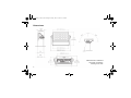
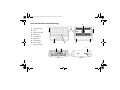
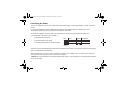
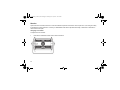
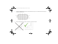
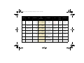
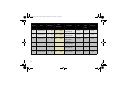
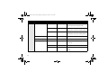
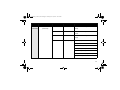
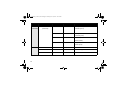
P2 Manual_170x113,3.book Page 1 Friday, June 19, 2015 10:12 AM P‐2 WASH LIGHT P2 Manual_170x113,3.book Page 2 Friday, June 19, 2015 10:12 AM Dimensions Measurements in millimetres and inches (in brackets). Drawing not to scale. 2 P2 Manual_170x113,3.book Page 3 Friday, June 19, 2015 10:12 AM P‐2 WASH LIGHT USER MANUAL © 2015 SGM®. Information subject to change without notice. SGM and all affiliated companies disclaim liability for any injury, damage, direct or indirect loss, consequential or economic loss or any other loss occasioned by the use of, inability to use or reliance on the information contained in this manual. The SGM logo, the SGM name and all other trademarks in this document pertaining to services or products by SGM or its affiliates and subsidiaries are trademarks owned or licensed by SGM or its affiliates or subsidiaries. The original edition of this document is in English. All other language editions are translations of the original edition. This edition applies to firmware version 1.10 or later. Ver. E 3 P2 Manual_170x113,3.book Page 4 Friday, June 19, 2015 10:12 AM Contents Dimensions ........................................................................................................................2 Safety information ..............................................................................................................6 Overview ............................................................................................................................9 Parts identification and terminology .................................................................................10 Preparing for installation ..................................................................................................11 Installing the P-2 ..............................................................................................................12 Connecting AC Power ......................................................................................................14 Configuring the fixture ......................................................................................................15 Setting a static color manually .........................................................................................16 Using stand-alone operation ............................................................................................17 Connecting to a DMX control device ................................................................................18 4 P2 Manual_170x113,3.book Page 5 Friday, June 19, 2015 10:12 AM Configuring the fixture for DMX control ............................................................................19 About DMX .................................................................................................................................................................... Setting the DMX address............................................................................................................................................... Setting the DMX mode................................................................................................................................................... Full Color Calibration and Color Temperature Correction (CTC)................................................................................... 19 19 20 21 Fixture personality settings ..............................................................................................22 Setting the dimming curve ............................................................................................................................................. Flipping the OLED display ............................................................................................................................................. Setting the OLED display saver..................................................................................................................................... Setting the fan mode...................................................................................................................................................... 22 22 22 23 Service .............................................................................................................................24 Changing lens module ................................................................................................................................................... 24 Upgrading the firmware ................................................................................................................................................. 27 Cleaning......................................................................................................................................................................... 27 DMX protocols ..................................................................................................................28 Control menu ....................................................................................................................41 Fixtures and accessories .................................................................................................47 Included items................................................................................................................................................................ 47 Ordering information ...................................................................................................................................................... 47 User’s notes .....................................................................................................................49 5 P2 Manual_170x113,3.book Page 6 Friday, June 19, 2015 10:12 AM Safety information WARNING! Read the safety precautions in this section before unpacking, installing, powering or operating this product. The P-2 is a multi-environmental fixture with an IP-rating of 65, intended for professional use only. It is not suitable for household use. Impropre a l’usage domestique. Review the following safety precautions carefully before installing or operating the fixture. This fixture must be installed in accordance with the applicable installation code by a person familiar with the construction and operation of the fixture and the hazards involved. Ce produit doit être installé selon le code d’installation pertinent, par une personne qui connaît bien le produit et son fonctionnement ainsi que les risques inhérent. Preventing electric shock WARNING! Risk of electric shock. • Always power off/unplug the fixture before removing any covers. • Ensure that the power is turned off when connecting the fixture to the AC mains supply. • Ensure that the fixture is electrically connected to earth (ground). • Do not apply power if the fixture is in any way damaged. • Do not immerse the fixture in water or liquid. 6 P2 Manual_170x113,3.book Page 7 Friday, June 19, 2015 10:12 AM Preventing burns and fire WARNING! Take measures to prevent burns and fire. • Install in a location that prevents accidental contact with the fixture. • Install only in a well-ventilated space. • Install at least 0.3 m (12 in.) away from objects to be illuminated. • Install only in accordance with applicable building codes. • Ensure a minimum clearance of 0.1 m (4 in.) around the cooling fans. • Do not paint, cover or modify the fixture. • Keep all flammable materials away from the fixture. • Allow the fixture to cool for 15 minutes after operation, before touching it. CAUTION: Exterior surface temperature after 5 min. operation = 45°C (113°F). Steady state = 60°C (140°F). 7 P2 Manual_170x113,3.book Page 8 Friday, June 19, 2015 10:12 AM Avoid personal injury WARNING! Take measure to prevent personal injury. • Do not look directly at the light source from close range. • Take precautions to prevent injury due to falls when working at height. • For permanent installation, ensure that the fixture is securely fastened to a load-bearing surface with suitable corrosion-resistant hardware. • For temporary installation with clamps, ensure that the quarter-turn fasteners are turned fully and secured with a suitable safety cable. The cable must be approved for a safe working load (SWL) of 10 times the weight of the fixture, and it must have a minimum gauge of 2 mm. 8 P2 Manual_170x113,3.book Page 9 Friday, June 19, 2015 10:12 AM Overview The P-2 is a DMX-controllable, low-profile, IP65-rated, rectangular, LED wash light. It has full RGBW color mixing, color temperature control and incorporates 18 high-power 10W RGBW LEDs divided into 3 individually controllable segments for wide ranging color and effect combinations. The P-2 offers a variation of beam angles with 15°, 21° or 43° interchangeable lenses. The P-2 also features dimming, RGB color mixing, color temperature control, and a lamp life expectancy of 50,000 hours*. This manual covers installation, use and maintenance of the P-2. All documentation is also available from the SGM web-site: http://www.sgmlight.com * At 70% of luminous output under the manufacturer’s test conditions. 9 P2 Manual_170x113,3.book Page 10 Friday, June 19, 2015 10:12 AM Parts identification and terminology D E E A 18 x 10W LEDs B Base C Safety wire eyelet D Cooling fan E Tilt brake lock F DMX in/out G OLED display H Control panel I Power connection A B G 10 H E I F C P2 Manual_170x113,3.book Page 11 Friday, June 19, 2015 10:12 AM Preparing for installation Unpack the fixture and inspect it to ensure that it has not been damaged during transport. The P-2 is shipped with an Omega bracket, that can be used to mount the fixture at elevation. The fixture is IP65-rated, and is designed for use in wet locations. This means that it is protected from: • Dust, to the degree that dust cannot enter the fixture in sufficient quantities as to interfere with its operation. • Lower pressure jets of water from any direction. When selecting a location for the fixture, ensure that: • It is situated away from public thoroughfares and protected from contact with people. • It is not immersed in water or exposed to high-pressure water jets. • It has adequate ventilation. 11 P2 Manual_170x113,3.book Page 12 Friday, June 19, 2015 10:12 AM Installing the P-2 The P-2 may be installed in any orientation, but if installed horizontally with a downward beam-angle, water can potentially pool in the fan wells. Under normal operation the moisture will evaporate. However, in locations with high rainfall, you may wish to fabricate a rain shield above the fixture, or modify the position and orientation of the fixture to minimize pooling. For permanent installation on the ground, remove the rubber feet from the floor stand/base. Fasten securely through the resulting holes with four 6 mm (1/4 in.) corrosion-resistant mechanical fasteners suitable for the location. 12 P2 Manual_170x113,3.book Page 13 Friday, June 19, 2015 10:12 AM One Omega bracket is supplied with the fixture if it is to be flown above the ground. Remove the floor stand/base and rig the P-2 to a support truss or structure using the supplied brackets and suitable clamps. Fasten a safety cable (not shown) between the support structure and the attachment point on the fixture. The safety cable must be able to bear at least 10 times the weight of the fixture. WARNING! Always secure an elevated P-2 with a safety cable as backup. The fixture can be tilted from 0° - 180°. To adjust the tilt angle, loosen the two tilt screws, one of each side of the fixture, tilt the fixture to the angle required and re-tighten the screws. CAUTION: If the fixture has been operating, always allow it to cool for 15 minutes before handling. 13 P2 Manual_170x113,3.book Page 14 Friday, June 19, 2015 10:12 AM Connecting AC Power The P-2 can operate on any 100–277V, 50/60 Hz AC mains power supply. It draws approximately 1.2 amps at full power (230V). For permanent installation, have a qualified electrician wire the mains cable directly to a suitable branch circuit. The junction’s ingress protection (IP) rating must be suitable for the location. For temporary installation, the mains cable may be fitted with a grounded connector intended for exterior use. The power cable color coding is given in Table 1-1. • Connect the black wire to live • Connect the white wire to neutral • Connect the green/yellow wire to ground (earth) Wire Color Symbol Black L White N green/yellow or Conductor live neutral ground (earth) Table 1-1 The fixture must be grounded/earthed and be able to be isolated from AC power. The AC power supply must incorporate a fuse or circuit breaker for fault protection. After connecting the P-2 to power, run the on-board test, using the “Test→Selftest” menu, to ensure that the fixture and each LED are functioning correctly. See “Control menu” on page 41. CAUTION: Do not open the fixture to replace the supplied power cable, or connect the fixture to an electrical dimmer system, as this can damage it. 14 P2 Manual_170x113,3.book Page 15 Friday, June 19, 2015 10:12 AM Configuring the fixture Set up the fixture using the control panel and OLED display at the top of the fixture. Navigate the menus and options using the arrow buttons and select items using the Enter button. The options available are listed in “Control menu” on page 41. After powering the P-2 on, the display shows the currently selected operating mode and other information. A - Operational mode (quick color, stand-alone or DMX mode) B - DMX address C - External data indicator (if DMX control is active) A 6CH MODE B C D 8 DMX D - External data protocol (DMX) The fixture is set by default to be controlled in DMX mode. 15 P2 Manual_170x113,3.book Page 16 Friday, June 19, 2015 10:12 AM Setting a static color manually The fixture can be configured to display a predefined and static color using the “Manual→Quick color” menus (see “Control menu” on page 41). Note that whenever the “Manual→Quick color” settings are changed, the fixture will be set by default to automatically start in quick color mode whenever it is powered on. This can be reset using the “Settings→Startup mode→Select startup mode” (see “Control menu” on page 41). 16 P2 Manual_170x113,3.book Page 17 Friday, June 19, 2015 10:12 AM Using stand-alone operation Stand-alone operation is where the fixture is not connected to a control device, but is preprogrammed with a series of up to 24 scenes, that play continuously in a loop. Up to three stand-alone programs can be defined and run from the menus, and one of the programs can be set to run by default whenever the fixture is started. Each of the three available stand-alone programs contains 24 user-definable scenes, each scene with its own RGBW (or white) and shutter settings. Each scene has a definable fade-in time, for the transition from one color (or white) to the next, and a wait (static) time, each of up to 999 minutes and 59 seconds in duration. To define a stand-alone program, use the “Manual→Editor” menus (see “Control menu” on page 41). Stand-alone mode at fixture startup is enabled using the “Settings→Startup mode→Select startup mode→Standalone” menu. The program to be run is selected using “Settings→Startup mode→Startup program” menu (see “Control menu” on page 41) for a description of the menus). The chosen program will run its length cyclically whenever the fixture is powered on. A program can be run at any time by selecting it using the “Manal→Run program” menu. 17 P2 Manual_170x113,3.book Page 18 Friday, June 19, 2015 10:12 AM Connecting to a DMX control device The fixture is controllable using a DMX control device and it can be connected using a DMX cable. If using a cabled DMX system, connect the DMX in cable (with male 5-pin XLR plug) and out cable (with female 5-pin XLR plug) to the DMX data link. Terminate the DMX out cable of the last fixture in the data link. For outdoor installations, use only IP-rated XLR connectors suitable for outdoor use. 18 P2 Manual_170x113,3.book Page 19 Friday, June 19, 2015 10:12 AM Configuring the fixture for DMX control About DMX The P-2 can be controlled using signals sent by a DMX controller on a number of channels (which varies depending on the DMX mode that has been set). The first channel used to receive data from a DMX control device is known as the DMX start address. Each P-2 must have a DMX start address set. For example, if a P-2 has a DMX address of 10 and it is in 3-channel DMX mode, then it uses channels 10, 11, and 12. The following fixture in the DMX chain could then be set to a DMX address of 13. If two or more DMX devices of the same type have the same DMX address, then they will mimic each other’s behavior. Incorrect settings will result in unpredictable responses to the lighting controller. Setting the DMX address The DMX address can be seen on the OLED display. To change the address setting, press the up and down arrows. When the desired address is displayed, press ‘Enter’ to save the setting. For your convenience, the suggested DMX address of the next fixture is displayed to the right. Note that channel spacing is determined by the DMX mode. SET DMX ADR 10 NEXT FIX 13 See the “DMX protocols” on page 28 for specific DMX control values. 19 P2 Manual_170x113,3.book Page 20 Friday, June 19, 2015 10:12 AM Setting the DMX mode Using the “DMX mode” menu available from the control panel, specify the DMX mode that provides the fixture controls that you require: P-2 DMX modes 20 Function 3 Individual control of color channels for red, green & blue. White is automatically mixed in. 6 RGBW, intensity, shutter, strobe, pulse & open shutter effects. 9 RGB with individual colour panel control. 12 RGB with individual colour panel control, intensity, shutter, strobe, pulse & open shutter effects. 15 RGBW, intensity, shutter, strobe, pulse & open shutter effects. 22 RGB with fine individual colour panel control, intensity, shutter, strobe, pulse & open shutter effects. P2 Manual_170x113,3.book Page 21 Friday, June 19, 2015 10:12 AM Full Color Calibration and Color Temperature Correction (CTC) All channel modes except 1 x RGB (3 Channel Mode) and 3 x RGB (9 Channel Mode): Lets you choose between raw or white-calibrated color (2000K - 10.000K) via the CTC channel. When you adjust the white color temperature, all RGB or RGBW channels (if available) must be set to 100%. 1 x RGB (3 Channel Mode) and 3 x RGB (9 Channel Mode): Features full color calibration when you mix 2 or 3 colors to ensure uniform color between products. Adjusting 1 color does not activate full color calibration. All channel modes except 1 x RGB (3 Channel Mode) and 3 x RGB (9 Channel Mode) 1 x RGB (3 Channel Mode) 3 x RGB (9 Channel Mode) Full Color Calibration Full Color Calibration Choose raw or white-calibrated color (2000K 10.000K) via the CTC channel. NOTE: When you adjust the white color temperature, all RGB or RGBW channels (if available) must be set to 100%. See “DMX protocols” on page 28 for more details. 21 P2 Manual_170x113,3.book Page 22 Friday, June 19, 2015 10:12 AM Fixture personality settings Setting the dimming curve The setting of the dimming curve will determine the fixture’s behavior, when changing the light intensity between 0% - 100%. Linear control provides uniform adjustment throughout the control action, whereas gamma corrected dimming provides finer control at low light levels, where the eye is more sensitive to change. By default, the P-2 uses gamma corrected dimming. For uniform response, set all fixtures to the same dimming curve. To set the desired dimming curve, use the “Settings→Dimming curve” menu. Flipping the OLED display If the fixture is installed hanging upside down, it might be useful to flip the display so that it is easier to read. To flip the display, use the “Settings→Flip display” menu, or press the up and down buttons on the control panel at the same time. Setting the OLED display saver By default the OLED display dims down after a short period when the control panel is not in use, but it can also be set to turn off completely. Pressing any key will always turn on the display or restore it to normal brightness. To change the display saver, use the “Settings→Display saver” menu. NOTE: To avoid the risk of display deterioration caused by long term use in permanent installations, it is recommended to use the “Display saver→Display off” setting. 22 P2 Manual_170x113,3.book Page 23 Friday, June 19, 2015 10:12 AM Setting the fan mode For operating environments where low-noise is a requirement or where the fixture will be operating in high temperatures, it is possible to adjust the default fan speed to low or high using the “Settings→Fan mode” menu. 23 P2 Manual_170x113,3.book Page 24 Friday, June 19, 2015 10:12 AM Service Apart from the lens module, there are no user-serviceable components in the fixture. Do not open the P-2, as doing so is likely to damage the ingress protection. Consult your SGM dealer if the fixture operates abnormally, is defective or otherwise in need of service or repair. Changing lens module To replace the lens module: 1 24 Unscrew the highlighted screws with a TX20 screwdriver. P2 Manual_170x113,3.book Page 25 Friday, June 19, 2015 10:12 AM 2 Dismantle the front and unscrew the highlighted front plugs with an Unbrako 6/HOP6 Allen key. 3 Take out the lens module. 4 Place the new lens on the PCB print spacers and carefully press the lens module in place. 25 P2 Manual_170x113,3.book Page 26 Friday, June 19, 2015 10:12 AM 5 Screw in the highlighted front plugs with an Unbrako 6/HOP6 Allen key (Nm 1,0) and place three Silica Gel bags (not included in lens kit) as shown. 6 Place the sealing frame (facing upwards - see below) on top of the lens module. 26 P2 Manual_170x113,3.book Page 27 Friday, June 19, 2015 10:12 AM 7 Place Front Assembly on top of the sealing frame. 8 Screw in the highlighted screws with a TX20 screwdriver (Nm 0,7) (see step 1). 9 Check that the sealing frame is evenly visible all the way around the lens module. Upgrading the firmware The firmware installed on the fixture can be identified using the “Info→Firmware version” menu. We recommend that you keep your fixture’s firmware up-to-date. Visit http://www.sgmlight.com to download the latest firmware. To perform firmware updates, you need a Windows-based personal computer and a SGM USB 5-Pin-XLR upload cable (available from your SGM distributor). Cleaning To maintain optimal performance, regular cleaning is essential. Cleaning schedules will vary depending on the operating environment, and the installation should therefore be checked at frequent intervals within the first few weeks of operation to see whether cleaning is necessary. This procedure will allow you to assess cleaning requirements in your particular situation. If in doubt, consult your SGM dealer for a suitable maintenance schedule. Clean the P-2 using a soft cloth dampened with a solution of water and a mild detergent. Do not use products that contain solvents, abrasives or caustic agents for cleaning, as they can cause damage to both hardware, cables and connectors. 27 P2 Manual_170x113,3.book Page 28 Friday, June 19, 2015 10:12 AM DMX protocols Configuring DMX is described in “Setting the DMX mode” on page 20. 15 Channel Mode (RAW) - Full RGBW control Channel 1 2 28 Name Shutter Intensity DMX value DMX percentage Default Description Info DMX Fader type value 0 7 0,0% 2,7% Closed 10 (3,9%) Snap 8 15 3,1% 5,9% Open 0 (0%) Fade 16 151 6,3% 59,2% Strobe Fast > Slow 0 (0%) Fade 152 175 59,6% 68,6% Pulse - Open Slow > Fast 0 (0%) Fade 176 199 69,0% 78,0% Pulse - Close Slow > Fast 0 (0%) Fade 200 244 78,4% 95,7% Strobe - Random Slow > Fast 0 (0%) Fade 245 255 96,1% 100.0% 0 (0%) Fade 0 255 0,0% 100,0% 0 (0%) Fade Open No light > Maximum light P2 Manual_170x113,3.book Page 29 Friday, June 19, 2015 10:12 AM Channel Name DMX value DMX percentage Default Description Info DMX Fader type value Only active 3 CTC 0 255 0,0% 100,0% 2000K - 10000K when 0 (0%) Fade Panel 1 0 (0%) Fade Panel 1 0 (0%) Fade Panel 1 0 (0%) Fade Panel 1 0 (0%) Fade Panel 2 0 (0%) Fade Panel 2 0 (0%) Fade channel > 4 4 RED Panel 1 0 255 0,0% 100,0% 5 GREEN Panel 1 0 255 0,0% 100,0% 6 BLUE Panel 1 0 255 0,0% 100,0% 7 WHITE Panel 1 0 255 0,0% 100,0% 8 RED Panel 2 0 255 0,0% 100,0% 9 GREEN Panel 2 0 255 0,0% 100,0% No RED > Maximum RED No GREEN > Maximum GREEN No BLUE > Maximum BLUE No WHITE > Maximum WHITE No RED > Maximum RED No GREEN > Maximum GREEN 29 P2 Manual_170x113,3.book Page 30 Friday, June 19, 2015 10:12 AM Channel 30 Name DMX value DMX percentage 10 BLUE Panel 2 0 255 0,0% 100,0% 11 WHITE Panel 2 0 255 0,0% 100,0% 12 RED Panel 3 0 255 0,0% 100,0% 13 GREEN Panel 3 0 255 0,0% 100,0% 14 BLUE Panel 3 0 255 0,0% 100,0% 15 WHITE Panel 3 0 255 0,0% 100,0% Default Description Info DMX Fader type value No BLUE > Maximum BLUE No WHITE > Maximum WHITE No RED > Maximum RED No GREEN > Maximum GREEN No BLUE > Maximum BLUE No WHITE > Maximum WHITE Panel 2 0 (0%) Fade Panel 2 0 (0%) Fade Panel 3 0 (0%) Fade Panel 3 0 (0%) Fade Panel 3 0 (0%) Fade Panel 3 0 (0%) Fade P2 Manual_170x113,3.book Page 31 Friday, June 19, 2015 10:12 AM 12 Channel mode - RGB (raw or white calibrated) Channel 1 Name Shutter DMX value DMX percentage Default Description Info DMX Fader type value 0 7 0,0% 2,7% Closed 10 (3,9%) Snap 8 15 3,1% 5,9% Open 0 (0%) Fade 16 151 6,3% 59,2% Strobe Fast > Slow 0 (0%) Fade 152 175 59,6% 68,6% Pulse - Open Slow > Fast 0 (0%) Fade 176 199 69,0% 78,0% Pulse - Close Slow > Fast 0 (0%) Fade 200 244 78,4% 95,7% Strobe - Random Slow > Fast 0 (0%) Fade 245 255 96,1% 100.0% 0 (0%) Fade 0 (0%) Fade 0 (0%) Fade 2 Intensity 0 255 0,0% 100,0% 3 CTC 0 255 0,0% 100,0% Open No light > Maximum light Only active 2000K - 10000K when channel > 4 31 P2 Manual_170x113,3.book Page 32 Friday, June 19, 2015 10:12 AM Channel 32 Name DMX value DMX percentage 4 RED Panel 1 0 255 0,0% 100,0% 5 GREEN Panel 1 0 255 0,0% 100,0% 6 BLUE Panel 1 0 255 0,0% 100,0% 7 RED Panel 2 0 255 0,0% 100,0% 8 GREEN Panel 2 0 255 0,0% 100,0% 9 BLUE Panel 2 0 255 0,0% 100,0% 10 RED Panel 3 0 255 0,0% 100,0% Default Description Info DMX Fader type value No RED > Maximum RED No GREEN > Maximum GREEN No BLUE > Maximum BLUE No RED > Maximum RED No GREEN > Maximum GREEN No BLUE > Maximum BLUE No RED > Maximum RED Panel 1 0 (0%) Fade Panel 1 0 (0%) Fade Panel 1 0 (0%) Fade Panel 2 0 (0%) Fade Panel 2 0 (0%) Fade Panel 2 0 (0%) Fade Panel 3 0 (0%) Fade P2 Manual_170x113,3.book Page 33 Friday, June 19, 2015 10:12 AM Channel Name DMX value DMX percentage 11 GREEN Panel 3 0 255 0,0% 100,0% 12 BLUE Panel 3 0 255 0,0% 100,0% Default Description Info DMX Fader type value No GREEN > Maximum GREEN No BLUE > Maximum BLUE Panel 3 0 (0%) Fade Panel 3 0 (0%) Fade 33 P2 Manual_170x113,3.book Page 34 Friday, June 19, 2015 10:12 AM 22 Channel Mode - 16 bit (raw or white-calibrated) Channel 1 2 3 Name DMX value DMX percentage Default Description DMX Fader type value 0 7 0,0% 2,7% Closed 8 15 3,1% 5,9% Open 16 151 6,3% 59,2% Strobe 152 175 59,6% 68,6% 176 199 69,0% 200 244 245 Intensity CTC Shutter Info 10 (3,9%) Snap 0 (0%) Fade Fast > Slow 0 (0%) Fade Pulse - Open Slow > Fast 0 (0%) Fade 78,0% Pulse - Close Slow > Fast 0 (0%) Fade 78,4% 95,7% Strobe - Random Slow > Fast 0 (0%) Fade 255 96,1% 100.0% 0 (0%) Fade 0 65535 0,0% 100,0% 0 (0%) Fade 0 255 0,0% 100,0% 0 (0%) Fade Open No light > Maximum light Only active 4 2000K - 10000K when channel > 4 34 P2 Manual_170x113,3.book Page 35 Friday, June 19, 2015 10:12 AM Channel 5 6 7 8 9 10 11 12 13 14 15 16 17 18 Name DMX value DMX percentage RED Panel 1 0 65535 0,0% 100,0% GREEN Panel 1 0 65535 0,0% 100,0% BLUE Panel 1 0 65535 0,0% 100,0% RED Panel 2 0 65535 0,0% 100,0% GREEN Panel 2 0 65535 0,0% 100,0% BLUE Panel 2 0 65535 0,0% 100,0% RED Panel 3 0 65535 0,0% 100,0% Default Description Info DMX Fader type value No RED > Maximum RED No GREEN > Maximum GREEN No BLUE > Maximum BLUE No RED > Maximum RED No GREEN > Maximum GREEN No BLUE > Maximum BLUE No RED > Maximum RED Panel 1 0 (0%) Fade Panel 1 0 (0%) Fade Panel 1 0 (0%) Fade Panel 2 0 (0%) Fade Panel 2 0 (0%) Fade Panel 2 0 (0%) Fade Panel 3 0 (0%) Fade 35 P2 Manual_170x113,3.book Page 36 Friday, June 19, 2015 10:12 AM Channel 19 20 21 22 36 Name DMX value DMX percentage GREEN Panel 3 0 65535 0,0% 100,0% BLUE Panel 3 0 65535 0,0% 100,0% Default Description Info DMX Fader type value No GREEN > Maximum GREEN No BLUE > Maximum BLUE Panel 3 0 (0%) Fade Panel 3 0 (0%) Fade P2 Manual_170x113,3.book Page 37 Friday, June 19, 2015 10:12 AM 6 Channel Mode (raw or white calibrated) Channel 1 Name Shutter DMX value DMX percentage Default Description Info DMX Fader type value 0 7 0,0% 2,7% Closed 8 15 3,1% 5,9% Open 16 151 6,3% 59,2% Strobe 152 175 59,6% 68,6% 176 199 69,0% 200 244 245 10 (3,9%) Snap 0 (0%) Fade Fast > Slow 0 (0%) Fade Pulse - Open Slow > Fast 0 (0%) Fade 78,0% Pulse - Close Slow > Fast 0 (0%) Fade 78,4% 95,7% Strobe - Random Slow > Fast 0 (0%) Fade 255 96,1% 100.0% 0 (0%) Fade 0 (0%) Fade 0 (0%) Fade 2 Intensity 0 255 0,0% 100,0% 3 CTC 0 255 0,0% 100,0% Open No light > Maximum light Only active 2000K - 10000K when channel > 4 37 P2 Manual_170x113,3.book Page 38 Friday, June 19, 2015 10:12 AM Channel 38 Name DMX value DMX percentage 4 RED All Panels 0 255 0,0% 100,0% 5 GREEN All Panels 0 255 0,0% 100,0% 6 BLUE All Panels 0 255 0,0% 100,0% Default Description Info DMX Fader type value No RED > Maximum RED No GREEN > Maximum GREEN No BLUE > Maximum BLUE All Panels 0 (0%) Fade All Panels 0 (0%) Fade All Panels 0 (0%) Fade P2 Manual_170x113,3.book Page 39 Friday, June 19, 2015 10:12 AM 9 Channel Mode - 3 x RGB (Full Color Calibration) Channel Name DMX value DMX percentage 1 RED Panel 1 0 255 0,0% 100,0% 2 GREEN Panel 1 0 255 0,0% 100,0% 3 BLUE Panel 1 0 255 0,0% 100,0% 4 RED Panel 2 0 255 0,0% 100,0% 5 GREEN Panel 2 0 255 0,0% 100,0% 6 BLUE Panel 2 0 255 0,0% 100,0% 7 RED Panel 3 0 255 0,0% 100,0% Default Description Info DMX Fader type value No RED > Maximum RED No GREEN > Maximum GREEN No BLUE > Maximum BLUE No RED > Maximum RED No GREEN > Maximum GREEN No BLUE > Maximum BLUE No RED > Maximum RED Panel 1 0 (0%) Fade Panel 1 0 (0%) Fade Panel 1 0 (0%) Fade Panel 2 0 (0%) Fade Panel 2 0 (0%) Fade Panel 2 0 (0%) Fade Panel 3 0 (0%) Fade 39 P2 Manual_170x113,3.book Page 40 Friday, June 19, 2015 10:12 AM Channel Name DMX value DMX percentage 8 GREEN Panel 3 0 255 0,0% 100,0% 9 BLUE Panel 3 0 255 0,0% 100,0% Default Description Info DMX Fader type value No GREEN > Maximum GREEN No BLUE > Maximum BLUE Panel 3 0 (0%) Fade Panel 3 0 (0%) Fade 3 Channel Mode - 1 x RGB (Full Color Calibration) Channel 40 Name DMX value DMX percentage 1 RED All Panels 0 255 0,0% 100,0% 2 GREEN All Panels 0 255 0,0% 100,0% 3 BLUE All Panels 0 255 0,0% 100,0% Default Description Info DMX Fader type value No RED > Maximum RED No GREEN > Maximum GREEN No BLUE > Maximum BLUE Panel 1 0 (0%) Fade Panel 1 0 (0%) Fade Panel 1 0 (0%) Fade P2 Manual_170x113,3.book Page 41 Friday, June 19, 2015 10:12 AM Control menu Level 1 Level 2 Level 3 Level 4 Function MODE SELECT MODE - - Select DMX mode. INFO PRODUCT TYPE - - Displays product type. FIRMWARE VERSION - - Displays software version. SERIAL NUMBER - - Displays serial number. RDM ID - - Displays RDM ID. DMX VIEW - - Displays received DMX channels. TEMPERATURES - - Displays temperatures (mainboard, left, center and right LED panel). POWER ON TIME - - Displays fixture lifetime. LED ON TIME - - Displays LED lifetime. LOG - - Displays recorded operation data and error codes. 41 P2 Manual_170x113,3.book Page 42 Friday, June 19, 2015 10:12 AM Level 1 Level 2 SETTINGS STARTUP MODE Level 3 Level 4 Function SELECT DMX Default operation mode when the STARTUP MODE STANDALONE fixture is powered on. Stand-alone QUICK COLOR program 1, 2, or 3 is the default. STARTUP Select 1, 2, or 3 PROGRAM FLIP DISPLAY DISPLAY SAVER ENABLE - Standard control panel display. DISABLE - Flips control panel display. DISPLAY DIM - Dims OLED display when control panel is not in use. DISPLAY OFF - Turns off OLED display when control panel is not in use. FAN MODE 42 STANDARD - SILENT - MAX POWER - P2 Manual_170x113,3.book Page 43 Friday, June 19, 2015 10:12 AM Level 1 Level 2 Level 3 Level 4 SETTINGS MINIMUM VALUES RED - (continued) Function Sets minimum values for individual segments. GREEN - BLUE - WHITE - FACTORY DEFAULT - - Restores factory default. SERVICE PIN - - Enter service pin to access service menu. SERVICE MENU PRODUCT TYPE - CALIBRATION - Service use only. INFO PSU VOLTAGE - PWM OUT - 43 P2 Manual_170x113,3.book Page 44 Friday, June 19, 2015 10:12 AM Level 1 Level 2 Level 3 Level 4 Function MANUAL QUICK COLOR RED - Static quick color - red mix (0-255). Sets fixture to quick color startup mode. GREEN - Static quick color - green mix (0-255). Sets fixture to quick color startup mode. BLUE - Static quick color - blue mix (0-255). Sets fixture to quick color startup mode. RUN PROGRAM 1, 2, OR 3 - STOP PROGRAM - - EDITOR PROGRAM - Currently selected program (1, 2, or 3). SCENE - Currently selected scene (1-24). RED - Red value in currently selected scene (0-255). 44 P2 Manual_170x113,3.book Page 45 Friday, June 19, 2015 10:12 AM Level 1 Level 2 Level 3 Level 4 Function MANUAL EDITOR GREEN - Green value in currently selected scene (continued) (continued) (0-255). BLUE - Blue value in currently selected scene (0-255). WHITE - White value in currently selected scene (0-255). SHUTTER Adjust (0-255) Blackout (0-7) Open (8-15) Variable Strobe (16-151) Pulse Open (152-175) Pulse Close (175-199) Variable Random Strobe (200-244) Open (245-255) 45 P2 Manual_170x113,3.book Page 46 Friday, June 19, 2015 10:12 AM Level 1 Level 2 Level 3 Level 4 Function MANUAL EDITOR FADE MIN. - Fade-in (transition) time to current scene (continued) (continued) in minutes (0-511). FADE SEC. - Fade-in (transition) time to current scene in seconds (0-59). WAIT MIN. - Wait (static) time to current scene in minutes (0-998). WAIT SEC. - Wait (static) time to current scene in seconds (0-59). TEST 46 SELFTEST - - Executes burn-in test. DISPLAY TEST - - Executes display test. COLOR TEST - - Executes color test. P2 Manual_170x113,3.book Page 47 Friday, June 19, 2015 10:12 AM Fixtures and accessories Included items Floor stand (including screws) Omega bracket User manual Neoprene pouch Ordering information P-2 Wash Light (43°) ..................................................................................................................................Order no: 80030528 P-2 Wash Light (21°) ..................................................................................................................................Order no: 80030526 P-2 Wash Light (15°) ..................................................................................................................................Order no: 80030529 SGM USB uploader cable .......................................................................................................................... Order no: 83062011 P-2 Lens kit (43°)........................................................................................................................................ Order no: 83061134 P-2 Lens kit (21°)........................................................................................................................................ Order no: 83061133 P-2 Lens kit (15°)........................................................................................................................................ Order no: 83061132 Accessory holder........................................................................................................................................ Order no: 83061127 Barn door 4-way ......................................................................................................................................... Order no: 83061129 Barn door 8-way ......................................................................................................................................... Order no: 83061130 Color frame................................................................................................................................................. Order no: 83061131 Omega bracket...........................................................................................................................................Order no: 83060602 Flight case (for 4 fixtures incl. barn doors) .................................................................................................Order no: 82051503 47 P2 Manual_170x113,3.book Page 48 Friday, June 19, 2015 10:12 AM APPROVALS AND CERTIFICATIONS Certified to ...........................................................................................................................................CSA E60598-1:02, Ed: 2 Certified to ......................................................................................................................................... CSA-E598-2-17-98, Ed: 1 Conforms to........................................................................................................................................................... UL Std. 1573 Conforms to.................................................................................................................................. 2004/108/EC: EMC Directive Conforms to........................................................................................................................ 2006/95/EC: Low Voltage Directive Conforms to.................................................................................................................................2011/65/EU: RoHS2 Directive 4008543 RoHS The information in this document is subject to change without notice 48 P2 Manual_170x113,3.book Page 49 Friday, June 19, 2015 10:12 AM User’s notes 49 P2 Manual_170x113,3.book Page 50 Friday, June 19, 2015 10:12 AM 50 P2 Manual_170x113,3.book Page 51 Friday, June 19, 2015 10:12 AM 51 P2 Manual_170x113,3.book Page 50 Friday, June 19, 2015 10:12 AM SGM A /S · Sommer vej 23 · 8210 Aarhus V · Denmark Tel +45 70 20 74 00 · [email protected] · www.sgmlight.com