1
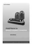
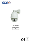
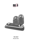
VPL7 Installation Set up Manual and user manual for the VPL7-WP-SM VPL7-WP-PM Fully functional dome camera Installation and user guide WARNING TO REDUCE THE RISK OF FIRE OR ELECTRIC SHOCK, DO NOT EXPOSE THIS PRODUCT TO RAIN OR MOISTURE. DO NOT INSERT ANY METALLIC OBJECTS THROUGH THE VENTILATION GRILLS OR OTHER OPENINGS ON THE EQUIPMENT. CAUTION EXPLANATION OF GRAPHICAL SYMBOLS The lightning flash with arrowhead symbol, within an equilateral triangle, is intended to alert the user to the presence of uninsulated “dangerous voltage” within the product’s enclosure that may be of sufficient magnitude to constitute a risk of electric shock to persons. The exclamation point within an equilateral is intended to alert the user to the presence of important operating and maintenance (servicing) instructions in the literature accompanying the appliance. CE COMPLIANCE STATEMENT WARNING This is a Class A product. In a domestic environment this product may cause radio interference in which case the user may be required to take adequate measures. II Before You Begin Read these instructions before installing or operating this product. Note: It is recommended that the camera is installed by personnel with a basic knowledge of CCTV systems and componentry, along with a knowledge of electrical wiring and low-voltage electrical connections. The CCTV system should be installed in conjunction with any CCTV and electrical guidelines/standards. Intended use Only use this product for its designated purpose; refer to the product specification and user documentation. Customer Support For assistance in installing, operating, maintaining and troubleshooting this product refer to this document and any other documentation provided. If you still have questions, please contact Norbain Technical Support and Sales: Norbain Ltd, 210 Wharfedale Road, IQ Winnersh Triangle, Wokingham, Berks RG41 5TP +44 (0) 118 912 5000 Note: You should be at the equipment and ready with details before calling Technical Support. RoHS Announcement All lead-free products offered by the company comply with the requirements of the European law on the Restriction of Hazardous Substances (RoHS) directive, which means our manufacture processes and products are strictly “lead-free” and without the hazardous substances cited in the directive. The crossed-out wheeled bin mark symbolizes that within the European Union the product must be collected separately at the product end-of-life. This applies to your product and any peripherals marked with this symbol. Do not dispose of these products as unsorted municipal waste. CE Mark This apparatus is manufactured to comply with the radio interference. A Declaration of Conformity in accordance with the following EU standards has been made. The manufacturer declares that the product supplied with this document is compliant the provisions of the EMC Directive 2004/108/ EC, the CE Marking Directive 93/68 EEC and all associated amendments. * This symbol indicates electrical warnings and cautions. ** This symbol indicates general warnings and cautions. NORBAIN LTD reserves the right to make changes to the product and specification of the product from time to time without prior notice. III IMPORTANT SAFETY INSTRUCTIONS 1. 2. 3. 4. 5. Read & keep these instructions. Heed all warnings & follow all instructions. Protect the power connections from moisture. Clean only with dry cloth. Do not block any ventilation openings. Install in accordance with the manufacturer’s instructions. 6. Do not install near any heat sources such as radiators, heat registers, stoves, or other apparatus (including amplifiers) that produce heat. 7. Do not defeat the safety purpose of any polarized or grounding-type plug. A polarized plug has two blades with one wider than the other. A grounding type plug has two blades and a third grounding prong. The wide blade or the third prong are provided for your safety. If the provided plug does not fit into your outlet, consult an electrician for replacement of the obsolete outlet. 8. Protect the power cord from being walked on or pinched particularly at plugs, convenience receptacles, and the point where they exit from the apparatus. 9. Only use attachments/accessories specified by the manufacturer. 10. Unplug this apparatus during lightning storms or when unused for long periods of time. 11. Refer all servicing to qualified service personnel. Servicing is required when the apparatus has been damaged in any way, such as powersupply cord or plug is damaged, liquid has been spilled or objects have fallen into the apparatus, the apparatus has been exposed to rain or moisture, does not operate normally, or has been dropped. 12. CAUTION – ANY SERVICING INSTRUCTIONS ARE FOR USE BY QUALIFIED SERVICE PERSONNEL ONLY. TO REDUCE THE RISK OF ELECTRIC SHOCK DO NOT PERFORM ANY SERVICING OTHER THAN THAT CONTAINED IN THE OPERATING INSTRUCTIONS UNLESS YOU ARE QUALIFIED TO DO SO. 13. Use Certified/Listed Class 2 power source only. IV Table of Contents Chapter 1 — Introduction........................................................................................................... 1 1.1 Features ............................................................................................................................ 1 Chapter 2 — Installation and Configuration ......................................................................... 2 2.0 Package Contents ............................................................................................................ 2 2.1 Installation ........................................................................................................................ 3 2.2 Connections...................................................................................................................... 4 2.3 Basic Configuration of Dome Camera System ............................................................... 5 2.4 Setting Dome Camera Termination ................................................................................. 6 2.5 Setting Dome Camera Address (ID) ................................................................................ 7 2.6 Setting Dome Camera Protocol ....................................................................................... 8 2.7 Getting Started.................................................................................................................. 9 2.8 How to control the On-Screen Menu ............................................................................. 10 2.9 Accessing the On-Screen Menu .................................................................................... 10 Chapter 3 — Program and Operation ................................................................................... 11 3.1 Auto Scan Setup ............................................................................................................. 11 3.2 Preset Setup ................................................................................................................... 12 3.3 Quick Setting a Preset.................................................................................................... 15 3.4 Tour Setup....................................................................................................................... 15 3.5 Pattern Setup (Learn Tour)............................................................................................. 16 3.6 Alarm Setup .................................................................................................................... 17 3.7 Area Title Setup .............................................................................................................. 17 3.8 Privacy Zone Setup ........................................................................................................ 18 3.9 Camera Setup ................................................................................................................. 19 3.10 Configuration Menu (Dome Setup) .............................................................................. 22 Appendix A — Specifications ................................................................................................. 30 Appendix B — Troubleshooting............................................................................................. 33 Appendix C — Glossary ........................................................................................................... 33 Appendix D — Dome Camera ID settings (17 - 255) ......................................................... 36 Appendix E — Surface Mounting the VPL7-WP-SM ......................................................... 42 V Chapter 1 — Introduction 1.1 Features Both VPL7 models are highly flexible, feature rich dome cameras, suitable for External & Internal use with a wide range of mounting options: 700TVL colour & monochrome resolution 1/4’ Sony Super HAD CCD II (960H) 22:1 optical zoom (3.9mm - 85.8mm) camera with x16 digital zoom and True Night Shot function 240 Preset positions with the individual Camera Auto Exposure (AE) settings 8 Tours consisting of Presets, Patterns, Auto Scan and other Tours can be programmed with over 300 functions and Preset locations, with either freeze or vector scan mode between each Preset position. 1 Auto Scan with normal, vector & random modes with 13 speed settings 8 Patterns (Learn tours) with up to 200 seconds learning ability available 8 Privacy Zones 16 Area Titles 4 Alarm input / 1 Alarm output (5VTTL) Variable speed from 0.1 /sec to 380 /sec Proportional Pan / Tilt speed (dependant on zoom ratio) Auto Calibration from 0.1 to 6 (Tilt range is 0 to 180 ) Programmable user preferences (alarm, preset, title, OSD display etc.) 180 Digital Flip Image flip – allows the camera to be mounted on the floor/ground for under vehicle surveillance Up to 255 selectable camera addresses Auto sensing RS485 telemetry supporting: Vista-485, Pelco P & D protocols Co-axial control with Vista-FSK Multi-language OSD: English, French, German, Italian, Spanish, Polish & Portuguese Optional Password Protection Home function capable of running any of the Preset, Tour, Pattern (learn tour) or Auto Scan functions 12VDC / 24VAC operation (12W) 24VAC (45W) for Heater & Fan providing operating temperatures of down to -30oC (VPL7-WP-PM only) Use Certified/Listed Class 2 power source only IP66 and built to IK10 for vandal resistance 1 Chapter 2 — Installation and Configuration 2.0 Package Contents The cameras are housed in compact housing, constructed of aluminum, steel and plastic, designed for wall, ceiling and pole mounting - the VPL7-WP-SM can also be floor mounted. Bracketry is not included, so please discuss with sales regarding mounting options and bracketry required to fulfill this. The housing meets the Protection Classification IP66 standards for dust and moisture ingress. * Dome Camera * Instruction Manual (This Document) * Accessory kit & connector 1) Torx wrench 2) 3Pin Terminal Block 3) 2Pin Terminal Block 4) 5Pin Terminal Block 5) Stainless Steel Mount Bracket 6) Mount Bracket screw 7) Mounting screws (PH6 x 35.0) 8) Plastic anchors 9) O-Rings 1 (SM or PM version) 1 1 1 1 (2 for the VPL7-WP-PM) 2 1 1 (only with the VPL7-WP-SM) 1 (only with the VPL7-WP-SM) 1 (only with the VPL7-WP-SM) 1 (only with the VPL7-WP-SM) 1 (only with the VPL7-WP-SM) Figure 1 – Packing List 2 2.1 Installation You may require additional bracketry to correctly install the dome – these brackets may be subject to change. If you are unsure then please contact us or your account manager for advice. General Guidance: The installation and fixing location must be capable of supporting the weight of the camera and any required bracketry. Installation notes: 1. Ensure the correct DIP switch settings are made and the cover plate is securely refitted before fixing the dome to any bracketry (THIS IS A PRIMARY SEAL). 2. Remove any protective tape/coverings attached to the dome camera. 3. When connecting any 2 threaded items together, the male thread should have a Teflon/PTFE tape to maintain the IP rating. 4. Place a bead of silicone sealant around the bracket and the wall to reduce the risk of moisture ingress. Cable Requirements For RS485 operation, the VPL7 requires video, power, alarm and data cables. The video cable carries the video signal to the recording/viewing point. If sending video via coaxial cable, a 75Ω pure copper coaxial cable is recommended for distances up to 250m. The VPL7 can be powered by either 12VDC or 24VAC (note that the VPL7-WP-PM heater & fan input requires 24VAC). The RS485 control cable carries commands from the keyboard/controlling device to the dome. An RS485 compatible shielded, two-conductor, twisted-pair cable is required (Belden 8723). Recommended cable size 24 gauge (0.56 mm). Alarms: Alarm cable is suitable or Cat 5 cable for longer distances up to 380m. For FSK control (Coaxial telemetry – Vista only), the data cable is not required. Pure copper coaxial cable and crimp-on BNC connectors are recommended. Do not use copper-coated steel cable and screw-on BNC connectors. 3 2.2 Connections • Connecting to the RS485 The dome camera can be controlled remotely by an external device or control system, such as a control keyboard, using RS485 half-duplex serial communications signals. • Connecting Video Output connector Connect the video output (BNC) connector to the monitor or video input. • Connecting Alarms A1, A2, A3, A4 (Alarm Input 1, 2, 3, 4) You can use external devices to signal the dome camera to react on events. Mechanical or electrical switches can be wired to the A1, A2, A3, A4 (Alarm Input 1, 2, 3, 4) and G (Ground) connectors. See Chapter 3 — Program and Operation for configuring alarm input. G (Ground) NOTE: All the connectors marked G or GND are common for alarms only (not to be used for 0V power input – there is a dedicated terminal for this). Connect the ground side of the alarm input and/or alarm output to the G (Ground) connector. AO (5VTTL Alarm Output) The dome camera can activate external devices such as buzzers or lights. Connect the device to the AO (Alarm Output) and G (Ground) connectors. Suitable activation may require the fitting of an additional actuator (relay) device. See Chapter 3 — Program and Operation for configuring alarm output. • Connecting the Power of Dome The dome will operate on either: 12VDC or 24VAC 1Amp power supply. Note: When using a 12VDC power supply the power input terminals ARE polarity dependant. E.g. Connect the positive (+) pole to the ‘+’ position and the negative (-) pole to the ‘-’ position. RED = 12VDC / WHITE = 0V Use certified / Listed Class 2 power source only. • Connecting the Power of Heater & Fan (VPL7-WP-PM only) This is a 24VAC input only and no less than a 2Amp (48W) supply is recommended for the heater & fan to operate correctly. In all power input requirements, use Certified / Listed Class 2 power sources only. 4 2.3 Basic Configuration of Dome Camera System NOTE: Only the VPL7-WP-PM has this connection (Pink & Brown) and is for the Heater and Fan Figure 2– Basic Installation Diagram 5 VPL7-WP-SM VPL7-WP-PM Figure 3 – Layout of DIP Switches NOTE: Open the switch cover (image ‘a’) to make any changes to the setting of DIP switches. This cover is a Primary Seal and as such needs to be refitted correctly once any DIP switch settings have been made. Failure to do this could allow moisture ingress, which may invalidate any warranty. 2.4 Setting Dome Camera Termination The device which is connected at each end of the data line, whether it is a dome camera or keyboard controller, must have the cable for communication terminated by setting the appropriate DIP switch. Without proper termination, there is potential for control signal errors. Total length of the cable for communication should not exceed 1.2km (4000ft). S3 S3 D1 Terminated ON Not terminated OFF Figure 4 – Setting Dome Camera Termination 6 2.5 Setting Dome Camera Address (ID) To ensure effective telemetry control of the dome, each dome camera must have a unique address (ID). When installing multiple dome cameras using a Multiplexer, DVR or Matrix, it is suggested that the dome camera address (ID) matches the camera input. The factory default setting is 1. Refer to Figure 5 for setting the dome camera address (ID). S1 NOTE: = ON position of DIP switch DOME ID 1 2 3 4 5 6 7 8 9 10 11 12 13 14 15 16 Switch Number 1 2 3 4 5 6 7 8 (1) (2) (4) (8) (16) (32) (64) (128) Figure 5 – Setting Dome Address (ID) Refer to Figure 9 in APPENDIX D for setting Dome Camera Address (ID) 17-255 7 2.6 Setting Dome Camera Protocol The Dome supports multiple telemetry protocols and has a default setting of Auto-sensing the RS485 protocol. Should Vista Coax telemetry be required (Vista-FSK) or if there are multiple RS485 protocol commands on the data line, then use the DIP switch settings below to force the camera to the required protocol. If you are not using a Vista Keyboard or DVR for the telemetry control then you may need to refer to the user manual for that product. You can set the Protocol with DIP switch D2, D3 and D4 in S2 below. DIP switch D1 has no function and is not used. S2 S2 PROTOCOL D2 D3 D4 OFF OFF OFF Vista-485, Pelco-P & D, F2 & 2E : default OFF OFF ON F2, F2E OFF ON ON Pelco-P & D ON ON OFF Vista-FSK ON OFF OFF Vista-485 You can set the Baud Rate with DIP switch D5 and D6 in S2. S2 BAUD RATE D5 D6 OFF OFF 2400 bps OFF ON 4800 bps ON OFF 9600 bps : default ON ON 19200 bps Figure 6 – Protocol, Baud rate Selection Switches 8 2.7 Getting Started Once installed, apply power to the dome camera. The dome camera will carry out a ‘start up’ sequence. The below screens are showing what can be displayed if required. AREA TITLE FUNCTION TITLE ABC 001 AF AE STATUS of FOCUS and AE CAMERA TITLE INFORMATION DISPLAY EMPTY DATA CAMERA ID ALARM:1 DOMEID:001 W→360.0 090.0 ALARM DISPLAY PAN & TILT ANGLE VIEW DIRECTION OSD Position The OSD display and layout can be customized in the OSD position setup. (AREA TITLE) (FUNC TITLE ) (AF AE) (CTRL KEY TO MOVE) SAVE AND EXIT(ESC TO CANCEL) (ALARM MESSAGE) (DOME ID…) (ANGLE…) OSD Position Setup Before you program or operate a dome camera, you must select the dome camera by pressing the No. + CAM keys from your controlling device (keyboard/DVR). Example: Pressing 1 & CAMERA keys from a Vista VKBD4 keyboard sequentially, will select camera 1. The selected dome camera ID will be displayed on the LCD display of the keyboard controller. 9 2.8 How to control the On-Screen Menu Please be aware that whilst the commands in BOLD in the table below are generic for most keyboards, DVR’s and popular protocols, if you are not using a Vista controller and Protocol then you may need to refer to the user manual for that controlling device to generate the required command. In any sub menu whereby ‘CONTROL’ is displayed onscreen and the (IO/FN) command is selected the screen the Joystick has full PTZ control of the camera. Function Action required / Button Press Command Open the On-Screen Menu Camera Menu Command Joystick Up, Down, Left, Right Moving the cursor Navigate through the menu. Joystick Up or Down Go into the sub-menu items. Joystick right or IRIS Open/FOCUS Near Keys (IO/FN) Changing values Enter the editing title mode. To enter the changing angle mode (e.g. presets, privacy etc). To exit the changing angle mode (e.g. presets, privacy etc) EXIT or Back a Step in the Menu Joystick left / right or Zoom via Joystick (Tele/Wide) IRIS Open/Focus Near (IO/FN) IRIS Close/Focus Far (IC/FF) Joystick left or IRIS Close/Focus Far (IC/FF) 2.9 Accessing the On-Screen Menu Once the configuration sequence has finished, you can call up the On-screen menu of the dome by entering the Dome menu: E.g. push and hold the CAMERA key and push MODE once on a VKBD4. This will bring up a password request screen. As default the Password for the dome is switched ON and to proceed to the main set up screen use the Joystick to move the cursor over the required character and select with the key push of (IO/FN). NOTE: The default password for the dome is: 5, menu and the following screen is displayed: 5, 5, 5, 5, 5 – you are now in the VPL7 DOME MENU AUTO SCAN PRESET TOUR PATTERN ALARM AREA TITLE PRIVACY ZONE CAMERA DOME SETUP FUNCTION RUN EXIT(ESC TO EXIT) 10 Chapter 3 — Program and Operation 3.1 Auto Scan Setup Allows the Dome to be set up to move automatically between 2 programmed locations, the Auto Scan can be recalled from the controlling device using the AUX6 command from a VKBD4. AUTO SCAN SETUP NUMBER : 01 TITLE : A01 MODE : NORMAL SPEED : 5 STEP START ANGLE : ----- ----END ANGLE : ----- ----SCAN DIR : CCW SWAP : OFF DWELL : 03 SEC SAVE AND EXIT(ESC TO CANCEL) NUMBER : 01 (cannot be changed – only 1no Auto Scan is available) TITLE : Up to 12 characters MODE : NORMAL, VECTOR, RANDOM NORMAL : Moves from the start angle to the end angle using only pan. VECTOR : Moves from the start angle to the end angle linearly applying pan, tilt and zoom. RANDOM : Moves randomly between the start angle to the end angle. SPEED : 1 - 13 steps, the lowest number means the slowest speed. START ANGLE : The 1st set of digits relates to the pan position, the 2nd set of digits relates to the tilt position. END ANGLE : The 1st set of digits relates to the pan position, the 2nd set of digits relates to the tilt position. SCAN DIR : Set the Scan direction, CCW (Counter Clock Wise), CW (Clock Wise). SWAP : Swaps the start angle for the end angle. DWELL : Sets the dwell time at the start & end points, between 01 - 99 seconds. Follow steps below to set up the Auto Scan: 1. TITLE – this can be changed one of two ways: Moving the Joystick left and right to select the cursor location and (Tele/Wide) to change the character. Use the Joystick to move the cursor to the alpha numeric character table displayed and select the required character with the (IO/FN) keys. TITLE EDIT MENU A01 * A B C D E F G H I J K L M N O P Q R S T U V W X Y Z 0 1 2 3 4 5 6 7 8 9 ( ) ALL DELETE EXIT(ESC TO EXIT) 11 2. Select ‘MODE’ - adjust with (Tele/Wide) 3. Select ‘SPEED’ - adjust with (Tele/Wide) 4. ‘START ANGLE’ Use the Joystick to move cursor to START ANGLE Press the (IO/FN) key ‘CONTROL’ is displayed. Move the camera to the desired location and the zoom position. Press the (IC/FF) and ‘CONTROL’ disappears and START ANGLE is now set. To fine tune the Pan and Tilt position use Joystick to move the cursor to the field you wish to change and twist the Joystick to adjust the position in increments of 0.1 degree. 5. ‘END ANGLE’ Use the Joystick to move cursor to END ANGLE. Press the (IO/FN) key ‘CONTROL’ is displayed. Move the camera to the desired location and the zoom position. Press the (IC/FF) and ‘CONTROL’ disappears and END ANGLE is now set. To fine tune the Pan and Tilt position use Joystick to move the cursor to the field you wish to change and twist the Joystick to adjust the position in increments of 0.1 degree. 6. Select ‘SCAN DIR’ to CCW or CW – adjust with (Tele/Wide) 7. Select ‘SWAP’. Set to ON, to swap the start angle and the end angle - adjust with (Tele/Wide) 8. Select ‘DWELL time’ – adjust with (Tele/Wide) 9. To save changes highlight ‘SAVE AND EXIT’ and move Joystick right. Joystick left exits without saving. 3.2 Preset Setup Up to 240 presets may be programmed. Presets can be recalled No. + PRESET. Presets on the VPL7 are very powerful and allow you to set the camera parameters and even a motion alarm for each preset. There are three pages of Preset menu. Each page has 80 Presets. The pages can be scrolled by moving the Joystick to the NEXT PAGE and (Tele/Wide) . PRESET SETUP NUMBER : 001 TITLE : --CAMERA SET DWELL : -- SEC 12345678901234567890 00 █**----------------02 -------------------04 -------------------06 -------------------NEXT PAGE SAVE AND EXIT(ESC TO CANCEL) - : a blank Preset position * : the position has a Preset already assigned █ : the current cursor position NOTE: Whilst the ‘NUMBER’ field at the top of this screen is adjustable, it does not update/auto populate the preset position lower down on the screen. So when setting up a preset position always use the lower part beneath ‘DWELL’ for this. Follow steps below to store the Preset positions: 12 1. Use the Joystick to move the cursor to the preset position you wish to add/adjust. 2. After selecting a preset position (blank or already populated), press the (IO/FN) key ‘CONTROL’ is displayed. Move to the desired location and zoom position then press the (IC/FF) key then ‘CONTROL’ disappears. The Preset for this location is then set. 3. Select ‘TITLE’ – this can be changed one of two ways: Moving the Joystick left and right to select the cursor location and (Tele/Wide) to change the character Use the Joystick to move the cursor to the alpha numeric character table displayed and select the required character with the (IO/FN) keys. 4. Select ‘CAMERA SET’ and move Joystick to the right, the Preset camera setup displays. PRESET CAMERA SETUP FOCUS : AUTO MOTION : OFF MOTION SETUP AE SETUP SAVE AND EXIT(ESC TO CANCEL) Set ‘FOCUS’ Set ‘MOTION’ : AUTO, MANUAL, ONE PUSH – adjust with (Tele/Wide : OFF, ON – adjust with (Tele/Wide) Select ‘MOTION SETUP’ and move the Joystick to the right, the ‘MOTION SETUP’ menu is displayed. MOTION SETUP SENSITIVITY : 06 POSITION : ALL DELAY : 00 SEC OUTPUT : OFF HOLD TIME : 03 SEC EXIT(ESC TO EXIT) Set SENSITIVITY Set POSITION Set DELAY Set OUTPUT Set HOLD TIME : 01 - 10 – adjust with (Tele/Wide) : ALL, CENTER – adjust with (Tele/Wide) : 00 - 05 seconds – adjust with (Tele/Wide) : OFF, ON – adjust with (Tele/Wide) : 03 - 99 seconds – adjust with (Tele/Wide) 13 Select ‘AE SETUP’ and move the Joystick to the right, the AE setup menu is displayed. AE SETUP MODE DSS LIMIT GAIN BRIGHT SHUTTER FLICKERLESS BACK LIGHT WDR WDR LEVEL NIGHT SHOT SAVE AND EXIT(ESC MODE AE1 AE2 SHUTTER PRIO MANUAL DSS LIMIT GAIN (AGC) BRIGHT SHUTTER FLICKERLESS BACK LIGHT WDR WDR LEVEL D/N MODE : MANUAL : OFF : MIN : 024 : 1/50 : --: OFF : --: --: AUTO TO CANCEL) AE1 / AE2 / SHUTTER PRIO / MANUAL Auto exposure mode1 (Set for normal surroundings: e.g. indoor) Auto exposure mode2 (Set for high brightness surroundings: e.g. outdoor) Variable Shutter speed, Auto Gain Variable Shutter speed, Gain OFF / x2 / x4 / x8 / x16 / x32 / x64 / x128 / x256 / x512 (Sense up) MIN / LOW / MID / HIGH 10 - 50 in steps of 1 1/50, 1/120, 1/250, 1/500, 1/1000, 1/2000, 1/10000, 1/100000 OFF / ON OFF / BLC / HLC (Peak White Inversion) (NOTE: When BLC or HLC is on, WDR will be disabled) OFF / ON (NOTE: When ON, BACK LIGHT will be disabled) LOW / MIDLOW / MID / MIDHIGH / HIGH AUTO / B/W / COLOUR The D/N mode option removes the IR cut filter of the camera and makes the camera sensitive to infrared illumination. AUTO B/W COLOUR Camera goes into B/W (monochrome) mode at low light (determined by the GAIN setting) Permanent monochrome mode Permanent colour mode These 3 settings can be temporarily overridden for a 60 second period via the day/night command function from the VKBD4. NOTE: BLC & HLC is either on or off and applied to the entire image. WDR operates in AE1 mode only. 5. Set ‘DWELL time’ (03 - 99 seconds in steps of 1) - adjust with (Tele/Wide) 6. To select the next page of Presets, scroll the page by moving the Joystick to the left or right on the first or last columns of the menu. 7. Repeat step 2 through 6 for each additional Preset position. 8. To save changes highlight ‘SAVE AND EXIT’ and move Joystick right. Joystick left exits without saving. 14 3.3 Quick Setting a Preset This can be achieved after selecting the desired scene e.g. with VKBD4 by pressing FUNCTION (Fn) then the No. (1 to 240) then PRESET key sequentially. The current view will be stored to the selected Preset number. If the Preset number is not empty, an ‘OVER WRITE’ message will be displayed on the screen and select to ‘OK’ or ‘Cancel’ as required and move the Joystick to the right to confirm. Example: FN, 1, 0, 1, PRESET keys will store current view as Preset no. 101. In this case, focus will be programmed as Auto, dwell time will be set to 3 second, and the current AE mode will be used. NOTE: If the password is set to ON within the Dome, then this will need to be entered to accept the new or when amending a Presete. 3.4 Tour Setup There are 8 programmable Tours. Each Tour consists of up to 42 Preset positions, Patterns, Scan or other Tours (second-level). Using second-level Tours, a Tour can be expanded to over 300 functions in a single Tour. Tours can be recalled No. + TOUR. TOUR SETUP NUMBER : 01 TITLE : T01 SCAN TYPE : NORMAL SPEED : 5 STEP DWELL : -- SEC 003 A04 --- --- --- --- ----- --- --- --- --- --- ----- --- P01 --- --- --- ----- T02 --- --- --- --- ----- --- --- --- --- --- ----- --- --- --- --- --- --SAVE AND EXIT(ESC TO CANCEL) --SCAN TYPE DWELL 003 A01 P01 T02 : Blank position : NORMAL, VECTOR : 03 - 99 seconds : Preset (1 - 240) : Auto Scan (1) : Pattern (1 - 8) : Tour (1 - 8) Follow the steps below to program the Tours: 1. Select ‘NUMBER’ and set the desired number by moving the Joystick to the left or right. 2. Choose a blank position to be programmed by moving the Joystick up, down, right, or left. 3. To scroll to a stored Preset, adjust with (Tele/Wide) then the stored Preset number displays. 4. To select functions other than Preset, press the (IO/FN) key to scroll for Tour, Pattern or Auto Scan respectively (if you wish to remove a Preset or Function from a Tour keep pushing (IO/FN) until ‘---‘ is displayed in the position). 5. Repeat step 1 through 4 for each desired position. Each title (if programmed) will be displayed on top of the line. 15 6. Select ‘TITLE’ – this can be changed one of two ways: Moving the Joystick left and right to select the cursor location and (Tele/Wide) to change the character Use the Joystick to move the cursor to the alpha numeric character table displayed and select the required character with the (IO/FN) keys. 7. To save changes highlight ‘SAVE AND EXIT’ and move Joystick right. Joystick left exits without saving. You can expand the Tour sequence by inserting another Tour into one of the ‘---‘ positions, just a as you would a Preset. NOTES: You cannot allocate a Preset or Function into a Tour without it being programmed first. The speed applies in Vector mode only. If you require the picture to ‘freeze’ between presets, this can be found in the cameras set-up menu. 3.5 Pattern Setup (Learn Tour) The Pattern feature records up to a maximum of 200 seconds of user control. Up to 8 Patterns can be stored, inserted into a Tour and played back by pressing the No. + Learn keys sequentially. PATTERN SETUP (CTRL KEY) NO TITLE SEC PERCENT 01 : P01 000 00.0% 02 : P02 000 00.0% 03 : P03 000 00.0% 04 : P04 000 00.0% 05 : P05 000 00.0% 06 : P06 000 00.0% 07 : P07 000 00.0% 08 : P08 000 00.0% TOTAL 000 00.0% SAVE AND EXIT(ESC TO CANCEL) Follow steps below to program the Pattern: 1. Select the desired Pattern to be programmed by moving the Joystick up or down. If the Pattern is not 000, a Pattern has already been recorded. Patterns can be overwritten. 2. Press the (IO/FN) key then the ‘CONTROL’ displays. Move the Dome through the required field of view applying zoom if required - the Dome movement will be automatically recorded. Press the (IC/FF) key then ‘CONTROL’ disappears. 3. To save changes highlight ‘SAVE AND EXIT’ and move Joystick right. Joystick left exits without saving. 4. Select ‘TITLE’ – this can be changed one of two ways: Moving the Joystick left and right to select the cursor location and (Tele/Wide) to change the character Use the Joystick to move the cursor to the alpha numeric character table displayed and select the required character with the (IO/FN) keys. NOTE: The 200 seconds of Pattern memory does not have to be evenly distributed across the Patterns. E.g. Pattern 1 can have entire 200 seconds allocated to it if required. Each dome movement uses memory to store the change – the % column shows how much of the total pattern memory has been used for each tour and also gives the running total at the bottom. 16 3.6 Alarm Setup Use the Joystick to move the cursor and (Tele/Wide) to adjust. To save changes highlight ‘SAVE AND EXIT’ and move Joystick right. Joystick left exits without saving. ALARM SETUP NO PRI FUN IN OUT 01 1 001 NO ON 02 1 --- OFF OFF 03 1 --- OFF OFF 04 1 --- OFF OFF DWELL : 03 SAVE AND EXIT(ESC TO NO PRI (Priority) FUN (Function) IN OUT HLD (Hold) LATCH DWELL HLD LATCH 03 OFF 03 OFF 03 OFF 03 OFF CANCEL) : Alarm input number (01 - 04) : The lower number has higher priority. (0 - 4) : Stored Preset or Function number to be called by alarm. : NO / NC – normally open/closed, OFF – ignore/off : ON – 5VTTL output, OFF – No output : Alarm will be held for the selected time (01 - 99 seconds) : ON – Alarm message will remain on the screen even though alarm input is deactivated. OFF – Alarm message will disappear from the screen after programmed hold time when alarm input is deactivated. : means the dwell time during multiple alarms, 03 to 99 seconds. There are 5 levels of priority, with 0 being the highest priority. The function allows Preset, Auto scan, Pattern or a Tour to be selected. Lower priority alarms will not occur until the higher priority alarm is completed. Alarms with equal priority will be rotate sequentially with the dwell time. 3.7 Area Title Setup Enter a specific name on a programmed angle between START and END. E.g. For the screen below, when the camera points at an angle between 124.3 (PAN), 30.7 (TILT) to 359.5 (PAN), 45.4 (TILT), ABC will be displayed on the screen. AREA TITLE SETUP NUMBER : 01 TITLE : ABC START ANGLE : 124.3 30.7 END ANGLE : 359.5 45.4 SWAP : OFF SAVE AND EXIT(ESC TO CANCEL) NUMBER TITLE SWAP : 01 - 16 : up to 12 characters. : Swap the START ANGLE for the END ANGLE. Follow steps below to program the Area Title: 1. Select ‘NUMBER’ and set the desired number by moving the Joystick to the left or right. 2. Select ‘TITLE’ – this can be changed one of two ways: Moving the Joystick left and right to select the cursor location and (Tele/Wide) to change the character Use the Joystick to move the cursor to the alpha numeric character table displayed and select the required character with the (IO/FN) keys. 17 3. Select ‘START ANGLE’. Press the (IO/FN) key, then ‘CONTROL’ is displayed. Move to the desired position. Press the (IC/FF) key then ‘CONTROL’ disappears. To adjust at the 0.1 degree interval, twist the Joystick at the pan field and the tilt field. 4. Select ‘END ANGLE’. Press the (IO/FN) key, then ‘CONTROL’ is displayed. Move to the desired position. Press the (IC/FF) key then ‘CONTROL’ disappears. To adjust at the 0.1 degree interval, twist the Joystick at the pan field and the tilt field. 5. Select ‘SWAP’. Set to ON, to swap the start angle and the end angle - adjust with (Tele/Wide) 6. To save changes highlight ‘SAVE AND EXIT’ and move Joystick right. Joystick left exits without saving. 3.8 Privacy Zone Setup There are 8 Privacy Zones available. NO 01 02 03 04 05 06 07 08 PRIVACY ZONE SETUP (CTRL KEY) TITLE METHOD ABC ON BLOCK OFF ---OFF ---OFF ---OFF ---OFF ---OFF ---OFF ---- SAVE AND EXIT(ESC TO CANCEL) NUMBER TITLE METHOD : 01 - 08 : up to 12 characters. : Block Follow steps below to program the Privacy Zone: 1. Select ‘TITLE’ – this can be changed one of two ways: Moving the Joystick left and right to select the cursor location and (Tele/Wide) to change the character Use the Joystick to move the cursor to the alpha numeric character table displayed and select the required character with the (IO/FN) keys. 2. Select the Privacy Zone you wish to set using the Joystick to highlight location. Press the (IO/FN) key, ‘CONTROL’ is displayed and Privacy Area Menu displays. Move to the desired position. Press the (IC/FF) key then ‘CONTROL’ disappears and returns to the previous menu. NOTE: The Privacy Zone is set to the actual screen size and NOT the Privacy Area ‘targeting’ display on the screen, so you will need to zoom in to suit. PRIVACY AREA MENU (CTRL KEY) CONTROL NUMBER 001 354.8 344.8 3. To select between on or off - adjust with (Tele/Wide) 4. To save changes highlight ‘SAVE AND EXIT’ and move Joystick right. Joystick left exits without saving. 18 3.9 Camera Setup Use the Joystick to move the cursor, right to select sub menu (if applicable) and (Tele/Wide) to adjust. To save changes highlight ‘SAVE AND EXIT’ and move Joystick right. Joystick left exits without saving. CAMERA SETUP FOCUS CONTROL WB CONTROL AE CONTROL DNR CONTROL LINE LOCK CONTROL SHARPNESS : 05 RESOLUTION : LOW DIGITAL ZOOM : OFF IMAGE FLIP : OFF PRESET FREEZE : OFF STABLIZATION : OFF SAVE AND EXIT(ESC TO CANCEL) SHARPNESS The higher the value, the more the edging in the picture will be enhanced (0 - 15) RESOLUTION Select resolution mode (LOW / MID / HIGH) DIGITAL ZOOM OFF: Optical zoom only. 2X: 2x digital zoom. 4X: 4x digital zoom. 8X: 8x digital zoom. MAX: 16x digital zoom. IMAGE FLIP This function turns the video output from the camera upside down, reverses it horizontally and corrects telemetry commands. NOTE: This allows the camera to be floor mounted PRESET FREEZE ON: The image from the previous Preset is held until the camera moves to the next Preset location. STABILIZATION ON: To increase the stability of an image from frame-to-frame jitter with minor vibrations/shaking. • FOCUS Set up Use the Joystick to move the cursor and (Tele/Wide) to adjust. To save changes highlight ‘SAVE AND EXIT’ and move Joystick right. Joystick left exits without saving. FOCUS SETUP MODE : MANUAL FOCUS LIMIT : 1.0M SAVE AND EXIT(ESC TO CANCEL) AUTO (AF) – Permanently in AF mode (no focal control override) MANUAL (MF) – In MF mode when moving, once stopped goes to AF for approx 4 secs then reverts to MF (focal control override) ONE PUSH – In MF mode when moving, once stopped goes to AF until moved again (focal control override) CONSTANT MANUAL – Permanently in MF mode (focal control override) use manual mode in normal use. FOCUS LIMIT This is approximate minimum distance that the focus will try to resolve. (1.0m, 1.5m, 2.5m and 6.0m) CAUTION: Avoid continuous, 24-hour use of the auto focus. This will shorten the lifespan of the lens. MODE 19 • WB Set up (White Balance) Use the Joystick to move the cursor and (Tele/Wide) to adjust. To save changes highlight ‘SAVE AND EXIT’ and move Joystick right. Joystick left exits without saving. WB SETUP MODE : AWB R GAIN : --B GAIN : --SAVE AND EXIT(ESC TO CANCEL) MODE AWB WAWB INDOOR OUTDOOR MANUAL R GAIN B GAIN AWB / WAWB / INDOOR / OUTDOOR / MANUAL Automatically computes the picture’s white balance using colour information from the entire screen. Wide range AWB mode Indoor white balance mode Outdoor white balance mode Manual white balance mode User changes R (Red) & B (Blue) Gain manually. 0 - 255 0 - 255 NOTE: R GAIN / B GAIN modes are only controllable in MANUAL Mode. • AE Setup (Auto Exposure) Use the Joystick to move the cursor and (Tele/Wide) to adjust. To save changes highlight ‘SAVE AND EXIT’ and move Joystick right. Joystick left exits without saving. AE SETUP MODE DSS LIMIT GAIN BRIGHT SHUTTER FLICKERLESS BACK LIGHT WDR WDR LEVEL NIGHT SHOT SAVE AND EXIT(ESC MODE AE1 AE2 SHUTTER PRIO MANUAL DSS LIMIT GAIN (AGC) BRIGHT SHUTTER FLICKERLESS BACK LIGHT : MANUAL : --: MIN : 024 : 1/50 : --: OFF : --: --: AUTO TO CANCEL) AE1 / AE2 / SHUTTER PRIO / MANUAL Auto exposure mode1 (Set for normal surroundings: e.g. indoor) Auto exposure mode2 (Set for high brightness surroundings: e.g. outdoor) Variable Shutter speed, Auto Gain Variable Shutter speed, Gain OFF / x2 / x4 / x8 / x16 / x32 / x64 / x128 / x256 / x512 (Sense up) MIN / LOW / MID / HIGH 10 - 50 in steps of 1 1/50, 1/120, 1/250, 1/500, 1/1000, 1/2000, 1/10000, 1/100000 OFF / ON OFF / BLC / HLC (Peak White Inversion) (NOTE: When BLC or HLC is ON, WDR will be disabled) 20 WDR WDR LEVEL D/N MODE OFF / ON (NOTE: When WDR is ON, BACKLIGHT will be disabled) LOW / MIDLOW / MID / MIDHIGH / HIGH AUTO / B/W / COLOUR The D/N mode option removes the IR cut filter of the camera and makes the camera sensitive to infrared illumination. AUTO B/W COLOUR Camera goes into B/W (monochrome) mode at low light (determined by the GAIN setting) monochrome mode colour mode These 3 settings can be temporarily overridden for a 60 second period via the day/night command function from the VKBD4. NOTE: BLC & HLC is either on or off and applied to the entire image. WDR operates in AE1 mode only. • DNR Setup Use the Joystick to move the cursor and (Tele/Wide) to adjust. To save changes highlight ‘SAVE AND EXIT’ and move Joystick right. Joystick left exits without saving. DNR SETUP 2DNR(1) 3DNR(1) 2DNR(2) 3DNR(2) SAVE AND EXIT(ESC 2DNR (1), 2DNR (2) 3DNR (1), 3DNR (2) : 003 : AUTO : 003 : 001 TO CANCEL) Select 2D noise reduction level (OFF / 1 - 7) Select 3D noise reduction level (AUTO / 1 - 28) NOTE: DNR (1) applied when motor stopped. DNR (2) applied when motor moving. • Line Lock Setup Use the Joystick to move the cursor and (Tele/Wide) to adjust. To save changes highlight ‘SAVE AND EXIT’ and move Joystick right. Joystick left exits without saving. LINE LOCK SETUP MODE : INTERNAL PHASE : 030 SAVE AND EXIT(ESC TO CANCEL) MODE PHASE INTERNAL / EXTERNAL Adjusts the phase of the picture with reference to other cameras in EXTERNAL mode (0 - 312). NOTE: Line lock is only available when the VPL7 is powered with 24VAC. With most modern digital control equipment, line lock is not normally required. 21 3.10 Configuration Menu (Dome Setup) Use the Joystick to move the cursor, right to select sub menu (if applicable) and (Tele/Wide) to adjust. To save changes highlight ‘SAVE AND EXIT’ and move Joystick right. Joystick left exits without saving. CONFIGURATION MENU LANGUAGE : ENGLISH HOME FUNCTION SETUP OSD DISPLAY VIEW ANGLE SETUP INITIALIZE DATA ORIGIN OFFSET DOME RESET SYSTEM MENU SYSTEM INFORMATION SAVE AND EXIT(ESC TO CANCEL) • LANGUAGE Setup LANGUAGE : Select the OSD language English / French / German / Italian / Spanish / Polish / Portuguese • HOME FUNCTION Setup HOME FUNCTION SETUP HOME FUNCTION FUNCTION NUMBER WAITING TIME FUNCTION ENABLE SAVE AND EXIT(ESC HOME FUNCTION FUNCTION NUMBER WAITING TIME FUNCTION ENABLE : NONE : --: 120 SEC : OFF TO CANCEL) : None / Tour / Pattern / Auto Scan / Preset :--: 10 - 240 seconds : ON / OFF The Home function can be set so that the camera automatically goes to a Tour, Pattern, Auto Scan or Preset after the keyboard controller has been idle for a specified amount of time. E.g. If the controller is idle for 120 seconds, the camera goes to Preset 1 after this time. Follow these steps to program the Home position: 1. Select ‘HOME FUNCTION’ by moving the Joystick and (Tele/Wide) to scroll through the None (---), Tour, Pattern, Auto Scan or Preset functions. 2. Select ‘FUNCTION NUMBER’ and (Tele/Wide) to scroll through the recorded function number. 3. Select ‘WAITING TIME’ and (Tele/Wide) to select between 10 to 240 seconds in 5 sec increments. 4. Select ‘FUNCTION ENABLE’ and adjust with (Tele/Wide) NOTE: Only pre-programmed presets and functions (tour / pattern / auto scan) can be used. 22 • OSD DISPLAY Setup Use the Joystick to move the cursor, right to select sub menu (if applicable) and (Tele/Wide) to adjust. To save changes highlight ‘SAVE AND EXIT’ and move Joystick right. Joystick left exits without saving. OSD DISPLAY SETUP CAMERA TITLE VIEW DIRECTION DOME OSD AREA TITLE PRESET TITLE FOCUS EXPOSURE OSD POSITION SETUP : : : : : : DOMEID OFF ON OFF CONSTANT ON SAVE AND EXIT(ESC TO CANCEL) CAMERA TITLE : up to 6 characters. VIEW DIRECTION : OFF / ON ‘ON’ sets current direction as N (North) and the coordinate angle to 000. ‘OFF’ hides the directional title. Every 90 degrees of clockwise rotation will change the title to E (East), S (South) and W (West). If using the ON/OFF option frequently, it is recommended to set ‘North’ as a Preset. Recall the ‘North’ Preset before enabling the directional title. DOME OSD : OFF / ON All displays or titling will disappear when DOME OSD DISPLAY is set to OFF. AREA TITLE : OFF / ON If this option is enabled, the area title displays when the camera moves. NOTE: The DOME OSD DISPLAY must be ON. PRESET TITLE : OFF / CONSTANT / 3, 30, 60,120,180 seconds Set the Preset title display time. FOCUS EXPOSURE : OFF / ON ON: FOCUS and EXPOSURE displays. (AF AE) OSD POSITION SETUP Select the OSD option with the Joystick up and down, press the (IO/FN) key and adjust the position by the Joystick. Press the (IC/FF) key to release. (AREA TITLE) (FUNC TITLE ) (AF AE) (CTRL KEY TO MOVE) SAVE AND EXIT(ESC TO CANCEL) (ALARM MESSAGE) 23 DOMEID:XXX XXX.X XXX.X • VIEW ANGLE Setup Use the Joystick to move the cursor and (Tele/Wide) to adjust. To save changes highlight ‘SAVE AND EXIT’ and move Joystick right. Joystick left exits without saving. VIEW ANGLE SETUP PANNING RANGE FLIP : TILT LIMIT : LIMIT ANGLE : SAVE AND EXIT(ESC TO 90 OFF --CANCEL) PANNING RANGE SETUP (Electronic Limit Stops) If the Dome is installed close to a wall or public boundary whereby the camera needs to be restricted from viewing this area then the panning range can be set up to stop this. PANNING RANGE SETUP (CTRL KEY) RIGHT LIMIT : 000.0 LEFT LIMIT : 000.0 ENABLE : OFF SWAP : OFF SAVE AND EXIT(ESC TO CANCEL) 1. Select ‘RIGHT LIMIT’. Press the (IO/FN) key, then ‘CONTROL’ is displayed. Move to the desired position. Press the (IC/FF) key then the ‘CONTROL’ disappears. 2. Select ‘LEFT LIMIT’. Press the (IO/FN) key, then ‘CONTROL’ is displayed. Move to the desired position. Press the (IC/FF) key then the ‘CONTROL’ disappears. 3. Select ‘ENABLE’. Set to ON - adjust with (Tele/Wide) 4. Select ‘SWAP’. Set to ON, to swap the start RIGHT & LEFT LIMITS - adjust with (Tele/Wide) 5. To save changes highlight ‘SAVE AND EXIT’ and move Joystick right. Joystick left exits without saving. FLIP: OFF/ AUTO / 90 / 100 / 110 / 120 OFF: The camera moves to the 90 point vertically and stops. AUTO: When the camera reaches the 90 point vertically, it rotates 180 and then tilt up in one action. When you use the panning range, it is recommended to use the flip mode to AUTO. 90 , 100 , 110 , 120 : Allows the image to flip digitally when the camera moves over the setting angle vertically. TILT LIMIT: OFF/ ON This option is designed to limit the view angle and to stop the camera viewing the housing and edge of the bubble. OFF: When this is off, the tilt range is the full tilt angle of 180o When you fully zoom out, the camera will see inside the housing which could lead to the focus hunting and distorted images at the horizon in certain lighting conditions. 24 ON: When this is on, the range of the tilt angle is limited to 10o - 170o This prevents the camera from seeing inside the housing/edge of the bubble which can cause focus / hunting issues. LIMIT ANGLE: OFF / ON When ON, the camera module tilts down by 10 , this can then be adjusted upwards in increments of 1 to fine tune / maximize the tilt angle without the camera seeing inside the housing. Adjust with (Tele/Wide) • INITIALIZE DATA Use the Joystick to move the cursor, right to select sub menu (if applicable) and (Tele/Wide) to adjust. To save changes highlight ‘SAVE AND EXIT’ and move Joystick right. Joystick left exits without saving. INITIALIZE DATA FACTORY DEFAULT ERASE PROGRAMMED DATA PRESET FOCUS DEFAULT EXIT(ESC TO EXIT) FACTORY DEFAULT Select ‘FACTORY DEFAULT’ to initialize the Data. Use the Joystick to move the cursor and right or (IO/FN) to accept selection. FACTORY DEFAULT ARE YOU SURE ? CANCEL OK ERASE PROGRAMMED DATA Use the Joystick to move the cursor and (Tele/Wide) to adjust. To save changes highlight ‘SAVE AND EXIT’ and move Joystick right. Joystick left exits without saving. Erase all stored data from the Flash-ROM of the selected dome camera. You will be asked to enter ON or OFF. If you desire to erase all data then select ‘ERASE’ to run, otherwise press the (IC/FF) key to exit without erasing. The erased data includes all stored data (Auto Scan, Preset, and Tour etc ….) except origin offset. The offset value is still valid after all data is erased. The offset value can be zero with default set of Offset origin menu. ERASE PROGRAMMED DATA AUTO SCAN : ON PRESET : ON TOUR : ON PATTERN : ON ALARM : ON AREA TITLE : ON PRIVACY ZONE : ON CAMERA : ON DOME SETUP : ON ERASE SAVE AND EXIT(ESC TO CANCEL) 25 PRESET FOCUS DEFAULT Use the Joystick to move the cursor and (Tele/Wide) to adjust. To save changes highlight ‘SAVE AND EXIT’ and move Joystick right. Joystick left exits without saving. This menu set the default mode of the focus when you save the Preset. PRESET FOCUS DEFAULT FOCUS : AUTO SAVE AND EXIT(ESC TO CANCEL) FOCUS : AUTO / MANUAL / ONE PUSH • OFFSET SETUP (Origin offset) Use the Joystick to move the cursor and (Tele/Wide) to adjust. To save changes highlight ‘SAVE AND EXIT’ and move Joystick right. Joystick left exits without saving. OFFSET SETUP (CTRL KEY) PAN OFFSET : TILT OFFSET : ENABLE : SAVE AND EXIT(ESC TO 000.0 000.0 OFF CANCEL) This feature is useful in aligning a new dome camera exactly the same as the previously installed Dome camera. Dome camera’s origin set and all data initialize option do not override offset values. Only the default set option in this menu will set the offset value to zero. This can be used to avoid ceiling obstructions. • DOME RESET Use the Joystick to move the cursor and right or (IO/FN) to accept selection. DOME RESET ARE YOU SURE ? CANCEL OK This feature is used to re-calibrate the orientation of a selected dome camera. Origin offset value is not affected by this function. (Offset is still valid after origin set) 26 • SYSTEM MENU Use the Joystick to move the cursor, right to select sub menu (if applicable) and (Tele/Wide) to adjust. To save changes highlight ‘SAVE AND EXIT’ and move Joystick right. Joystick left exits without saving. SYSTEM MENU MOTOR SETUP PASSWORD EDIT ORIGIN CHECK WHITE DEFECT COMPENSATION CALIBRATION : ON PASSWORD ENABLE : ON MENU TIME OUT : ON BLINK CURSOR : ON DOME ANSWER : OFF SAVE AND EXIT(ESC TO CANCEL) CALIBRATION PASSWORD ENABLE MENU TIME OUT BLINK CURSOR DOME ANSWER : ON (Auto origin check) / OFF : ON (requires the password to enter menu) / OFF : ON (5minutes) / OFF (menu always on) : ON / OFF (no blinking cursor) : ON / OFF (no acknowledge command from the dome. This option should be left OFF unless the keyboard/DVR/controlling device and/or Protocol specifically ask for it to be switched ON. MOTOR SETUP Use the Joystick to move the cursor and (Tele/Wide) to adjust. To save changes highlight ‘SAVE AND EXIT’ and move Joystick right. Joystick left exits without saving. MOTOR SETUP PROPORTIONAL P/T P/T MODE : ON : NORMAL SAVE AND EXIT(ESC TO CANCEL) PROPORTIONAL P/T : ON / OFF P/T MODE : SLOW / NORMAL / TURBO SLOW MAXIMUM MANUAL SPEED : 40 /second NORMAL MAXIMUM MANUAL SPEED : 90 /second TURBO MAXIMUM MANUAL SPEED : 380 /second 27 PASSWORD EDIT SETUP Use the Joystick to move the cursor and (IO/FN) to accept character entry. PASSWORD EDIT SETUP (CTRL KEY) INPUT PASSWORD PASSWORD : A K U 4 B L V 5 C M W 6 D N X 7 E O Y 8 F P Z 9 G Q 0 ( H I J R S T 1 2 3 ) SAVE AND EXIT(ESC TO CANCEL) You can change the password to a 6 character alpha numeric type in this menu, once entered you will required to enter it a 2nd time to confirm. The default password is 5, 5, 5, 5, 5, 5 NOTE: Please keep a safe record of your password. If it is lost then the dome may need to be returned to gain access to the menus. ORIGIN CHECK If the presets or privacy zones appear to have moved, carry out an origin check as this will re zero the camera module position. Use the Joystick to move the cursor and right or (IO/FN) to accept selection. ORIGIN CHECK ARE YOU SURE ? CANCEL OK WHITE DEFECT COMPENSATION It is perfectly normal for a camera CCD to have what is known as ‘dead’, ‘hot’ or ‘white’ pixels, develop over time and on occasion and these can be noticeable on the viewed image. These can be masked easily without affecting the quality of the image with the White Defect Compensation function. WHITE DEFECT COMPENSATION ARE YOU SURE ? CANCEL OK 28 • SYSTEM INFORMATION SYSTEM INFORMATION CAMERA TYPE H/W VERSION ROM VERSION PROTOCOL BAUDRATE : : : : : VPL7 Vx.xxxx Vx.xx-xxxx Vx.xxxxx xxxx 9600 EXIT(ESC TO EXIT) The system information provides essential information about the dome camera if you need to contact technical assistance. When you view this screen, you can determine the camera type, ROM version. The information on this screen cannot be modified. 29 Appendix A — Specifications VPL7-WP-SM Resolution CCD Total Pixels Effective Pixels Scanning System Scanning Frequency Optical / Digital Zoom Focal length Horizontal angle of view F-Stop VPL7-WP-PM 700TVL 1/4" SONY Super HAD CCD II (960H) 1028(H) x 596(V) 976(H) x 582(V) 2:1 Interlace PAL : 15.625KHz (H) x 50Hz (V) 22:1 / 16x f3.9mm - 85.8mm 3.9mm – 49.5° 85.8mm – 2.4° F1.6 – F3.7 0.1Lux (Colour) Min Illumination 0.01Lux (Monochrome) 0.00001 Lux (Mono & DSS x512) S/N Ratio 50dB (AGC off) Day/Night Colour / B/W / AUTO WDR Off / On (Low / MidLow / Mid / MidHigh / High) BLC Off / BLC / HLC (PWI) DSS (Sense-up) Off / x2 to x512 Motion Detection Off / On (in Preset) Tilt angle 0° - 180° with 1° - 10° tilt adjustment Image Flip Off / On Auto Calibration 0.1° - 6° Panning angle 360° continuous rotation Max Speed 380° /sec. Alarms 4 inputs (NC/NO), 1 output (5VTTL) Auto Scan 1 Auto Scan (Normal / Vector / Random) Preset 240 presets with titles & individual camera AE setup Pattern 8 patterns (recording up to 200 sec.) Tour 8 tours (consist of 42 presets / functions) Area Title 16 areas with title (upto 12 characters) Privacy Zone 8 privacy zones OSD Languages GB / FR / DE / IT / ES / PL / PT RS-485: Auto sensing / Vista-485 / Pelco P & D / Fastrax 2 & 2E Telemetry Control Coaxial: Vista-FSK Baud Rate 2400 / 4800 / 9600 / 19200 ID (Camera Address) 1 – 255 Video Connection BNC Video Output 1.0 Vp-p (75 ohm, composite) Ø154 x 140 (H) / Bubble diameter Ø186 x 205 (H) / Bubble diameter Dimension (unit) Ø110 mm Ø110 mm Dimension (boxed) 225(H) x 220(W) x 220(D) mm 335(H) x 290(W) x 290(D) mm Weight (net) 1.5Kg 2.2Kg Weight (gross) 2.1Kg 3.1Kg -10°C to 50°C (14°F to 122°F) Operating temperature -10°C to 50°C (14°F to 122°F) -30°C to 50°C (-22°F to 122°F) (with aux Heater & Fan connected) Operating humidity 0 to 90%RH (non-condensing) Storage temperature -20 C to 60 C (-4 F to 140 F) IP Rating IP66 Vandal Resistance Built to IK10 (EN 62262) 12VDC (-10 to 15%) / 24VAC (±10%) Power Source 12VDC (-10 to 15%) / 24VAC (±10%) 24VAC ± 10% for Heater & Fan connection 12W Power Consumption 12W 45W (with aux Heater & Fan connected) * Specifications are subject to change without notice * 30 VPL7-WP-SM 31 VPL7-WP-PM Integral 1½ NPT thread for fitting to bracketry Figure 7 – Dimensions 32 Appendix B — Troubleshooting If problems occur, verify the installation of the camera with the instructions in this manual and with other operating equipment. Isolate the problem to the specific piece of equipment in the system and refer to the equipment manual for further information. Problem Possible Solution No video Verify that power is connected to all pieces of equipment in the system. Verify that the power switches are in the ON position. Check the video connections. Poor video quality. Check that the BNC connectors are inserted properly. Check the voltage level of the dome camera. Cable for video is shielded. Dome cameras lose their positions. Reset the cameras using the Dome configuration menus. Check that the dome cameras are inserted properly in the base. Check the voltage level of the dome camera. Camera number does not match the multiplexer number. Check the camera ID and insert the BNC cable into the proper input of the multiplexer. Picture is torn when switching. Check Line Lock setting and adjust phase of L/L. Figure 8 – Troubleshooting Appendix C — Glossary Alarm Action The assigned response for the dome when the alarm input changes. The dome may run a Preset, Pattern, or have no assigned action for 4 dome inputs. The dome may also send alarm state to the host controller for processing. See also Input Alarm and Normal Input State. Area A user defined start and end point of the dome's field of view around its pan axis. Each area is a part of a circular viewing area that extends around the dome. The areas can be different sizes. Up to 16 areas can be programmed for the dome. Automatic Gain Control (AGC) Allows for the amplification of the video signal in scenes with minimal ambient light. Many lowlight scenes result in picture noise. As gain is increased, the picture noise is also amplified. When AGC is enabled, the value of the gain setting is based on feedback from the camera. When AGC is disabled, the camera uses the value set for the manual gain setting. The trade-off between picture level and noise may be adjusted when AGC is disabled. On-screen Menu The text overlay menu system used for setting dome features. The utility is accessed using a combination of keystrokes (DVR dependant). The utility provides settings for camera functions, zoom, alarm, text display, and password protection. 33 Flip Allows the dome to automatically turn 180o when the camera tilts to its lower limit and stays in that position for a brief delay. When the dome flips (rotates), the camera starts moving upward as long as the tilt control is kept in the down position. Once the control is released, the tilt control returns to its normal operational mode. This flip feature is useful when you need to track someone who walks directly beneath the dome and continues on the other side. Home Position The default position to which the dome camera returns after an assigned period of inactivity have elapsed. The default position may be a Preset, Tour, Pattern, or No Action. Input Alarms (Alarm Inputs) Connection points on the dome camera that enables the system to monitor Input Devices (movement detectors / magnetic contacts etc). There are 4 alarm inputs available for the VPL7 dome camera. Input Device External devices that provide information about the condition of system components that connect to the input on the dome camera. Typical input devices include door contacts, motion detectors and smoke detectors. IR Mode Allows manual or automatic switching between colour and monochrome (IR sensitive) operation. When IR mode is active, clearer images may be obtained under low-light conditions. Line Lock Allows you to lock the start of the dome’s picture with reference to the AC power line. When line lock is enabled, it helps prevents vertical video rolling when switching multiple cameras to a single monitor. If text appears slightly tinted on color monitors, disabling the line lock may prevent this problem. Name Information Relates to the display of the dome name, the area where the dome is pointing, the name of the Preset or Pattern that is running, and alarm name. The display of each type of name setting can be enabled or disabled. When the display of camera or area title (name) is enabled, the information appears on the screen continuously. Preset, Tour and Pattern titles (names) appear only while they are active. Normal Input State Describes the expected state of a device connected to dome camera’s input. The normal state may be open or closed. When a device is not in its normal input state, an alarm is issued. North Position User-definable setting that may correspond to magnetic north or some well-known landmark. Used to display the approximate orientation of the dome. DSS (Slow Shutter/Sense up) Setting used to improve the quality of video obtained in extreme low-light situations. When the Slow Shutter setting is enabled, low-light information is collected over multiple fields based on the Shutter Limit setting. As a result, video may appear blurred or choppy in extreme low-light situations. This setting does not effect camera operation in normal lighting situations. 34 Pattern (Learn Tours) A series of pan, tilt, zoom and focus movements from a single programmable dome. Up to 8 Patterns may be programmed for the dome camera. Preset Programmed video scene, based on a specific pan, tilt, zoom, and focus settings. Up to 240 Presets may be programmed for the dome camera. Privacy Zone Masked areas of the dome camera's viewing area. These masks prevent operators of the surveillance system from viewing these designated zones. The Privacy Zones move in relation to the dome camera’s pan/tilt position. In addition, the apparent size of the Privacy Zone adjusts automatically as the lens zooms in or out. Up to 8 Privacy Zones may be established for a dome camera. Vector Scan Move from start point to end point including tilt and zoom simultaneously and linearly. White balance Adjustment of the picture’s hue, so that true white appears white in the image. It is normally compensated for by the automatic gain control. In some lighting conditions, you may need to manually adjust the red and blue settings for optimal viewing. When Automatic White Balance is enabled, the camera measures the image and automatically adjusts the red and blue settings to balance white. When Automatic White Balance is disabled, the camera uses the values set for the red and blue settings to balance white. 35 Appendix D — Dome Camera ID settings (17 - 255) Figure 9 – Dome Addresses 17-255 DOME ID 17 18 19 20 21 22 23 24 25 26 27 28 29 30 31 32 33 34 35 36 37 38 39 40 41 42 43 44 45 46 47 48 49 50 51 52 53 54 55 56 57 58 59 60 Switch Number 1 2 3 4 5 6 7 (1) (2) (4) (8) (16) (32) (64) 36 8 (128) Dome Camera ID settings (17 - 255) cont: DOME ID 61 62 63 64 65 66 67 68 69 70 71 72 73 74 75 76 77 78 79 80 81 82 83 84 85 86 87 88 89 90 91 92 93 94 95 96 97 98 99 100 Switch Number 1 2 3 4 5 6 7 (1) (2) (4) (8) (16) (32) (64) 37 8 (128) Dome Camera ID settings (17 - 255) cont: DOME ID 101 102 103 104 105 106 107 108 109 110 111 112 113 114 115 116 117 118 119 120 121 122 123 124 125 126 127 128 129 130 131 132 133 134 135 136 137 138 139 140 Switch Number 1 2 3 4 5 6 7 (1) (2) (4) (8) (16) (32) (64) 38 8 (128) Dome Camera ID settings (17 - 255) cont: DOME ID 141 142 143 144 145 146 147 148 149 150 151 152 153 154 155 156 157 158 159 160 161 162 163 164 165 166 167 168 169 170 171 172 173 174 175 176 177 178 179 180 Switch Number 1 2 3 4 5 6 7 (1) (2) (4) (8) (16) (32) (64) 39 8 (128) Dome Camera ID settings (17 - 255) cont: DOME ID 181 182 183 184 185 186 187 188 189 190 191 192 193 194 195 196 197 198 199 200 201 202 203 204 205 206 207 208 209 210 211 212 213 214 215 216 217 218 219 220 Switch Number 1 2 3 4 5 6 7 (1) (2) (4) (8) (16) (32) (64) 40 8 (128) Dome Camera ID settings (17 - 255) cont: DOME ID 221 222 223 224 225 226 227 228 229 230 231 232 233 234 235 236 237 238 239 240 241 242 243 244 245 246 247 248 249 250 251 252 253 254 255 Switch Number 1 2 3 4 5 6 7 (1) (2) (4) (8) (16) (32) (64) 41 8 (128) Appendix E — Surface Mounting the VPL7-WP-SM The studs protruding from the dome are designed to fit into the provided stainless steel mount bracket in a bayonet (twist fit) configuration – they are not to be adjusted. Once the dome has been fitted to the installed Mount Bracket it is essential that the mounting screw (in the right hand side diagram) as this is a locking screw and needs to be fitted to secure the dome and stop it being removed. There are many External & Internal mounting options available for both the VPL7-WPSM and VPL7-WP-PM. If you are unsure of which bracketry to use for the application then please consult with the Norbain sales team. 42 (Note: this manual is subject to being updated without notice) VPL7 Manual version 1.2 (2013/05/29)