1
3. INSTALLATION
POSITIONING
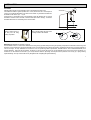
Selecting optimal location for the transmitter various considerations should be made.
If the measured material is granule (material size > 5 mm) and the tank roof is dome shaped or
conical, do not install the transmitter in the centre of the tank/silo. In general the transmitter can
be installed on the radius r= (0,3 … 0,5) R.
Avoid that the 5° conical beam angle of the transmitter contact the tank/silo wall. In case the
transmitter is mounted close to the wall, it should be tilted (See section “Aiming”). Protect the
transmitter electronics from overheating due to direct sunshine..
Sunshade
r
R
GRAVITY FILLING
PNEUMATIC FILLING
Select a location that is as
far away from the filling
point(s) as possible.
Select a location where the speed of the
in-flowing material is the smallest.
Suggested location (view from above)
40 m
3,8 m
50 m
4,7 m
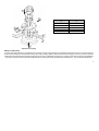
MOUNTING (See illustration for mounting on page 9)
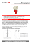
The EchoTREK consists of a sensor that is attached to the aiming arm (a pipe with a ball-joint housing incorporating a ball joint) that is attached to the housing of the
electronics. It is recommended to mount the transmitter on the roof of the tank/silo using a flange (See drawing). The Ball-joint housing has a screw-hole diameter of
125 mm for fixing it. For easy installation we recommend to use our special flange with a split insertion, available with four sizes of DN125/150/200/300 (to be
ordered separately). Removing the split insertion, the flange is to be put around the aiming arm and the ball-joint housing is to be fixed to the split flange. It is
essential to use the washers and the bolts (4 pcs each) delovered with the split flange. The ball-joint will be pressed to the housing by a spring allowing
adjustment/aiming. The 4 pcs of M12 bolts has only be tightened after completing the adjustment/aiming.
7