1
FS2020™ Stationary Transceiver
User Manual
Initial Release
Firmware Version: 1.3
Biomark, Inc.
705 S. 8th Street
Boise, Idaho 83702, USA
1-208-275-0011
Copyright and Trademarks
Copyright
© Copyright 2011 - 2012 Destron Fearing Corporation. All rights reserved. This manual contains
valuable proprietary information. It should not be published, copied, or communicated to any
person without prior authorization from Biomark, Inc.
Trademarks
FS2020 is a trademark of Destron Fearing Corporation.
Lantronix DeviceInstaller is a trademark of Lantronix, Inc.
Microsoft and Windows are registered trademarks of Microsoft Corporation.
All other trademarks, trade names, or images mentioned herein belong to their respective
owners.
Document History
Release Date
Doc Version
Firmware Version
Comments
April 2011
Draft
1.00D
Review version of this manual.
November 2012
Initial release
1.3
Initial release of this manual.
READ THROUGH THIS ENTIRE MANUAL BEFORE INSTALLING AND OPERATING
YOUR TRANSCEIVER. FOLLOW ALL STEPS EXACTLY. USING THE
TRANSCEIVER IN A MANNER FOR WHICH IT WAS NOT DESIGNED MAY IMPAIR
THE SAFETY FEATURES BUILT IN BY THE MANUFACTURER.
Safety Symbols
Indicates care should be taken to avoid physical harm. Only qualified service
personnel should access the internal components of the transceiver.
.
ii
FS2020 User Manual
Table of Contents
Table of Contents
Product Description .....................................................................................................................1
Specifications ..................................................................................................................2
Control Panel Component Identification ...........................................................................3
Port Identification .............................................................................................................4
Major Internal Hardware Components .............................................................................6
DC Power Supply .................................................................................................7
Mother Board .......................................................................................................8
User Interface Board ............................................................................................9
Antenna Interface Board ....................................................................................10
Remote Communication Board ..........................................................................11
Installation and System Configuration .......................................................................................12
Installing and Powering Up the Transceiver ...................................................................12
Tuning the Antenna .......................................................................................................13
Coarse-tuning the Antenna.................................................................................13
Fine-tuning the Antenna and Dynamic Tuning ....................................................14
Setting the Antenna Dynamic Tuning Responsiveness ...................................... 15
Fine-tuning the Transceiver ...........................................................................................16
Tools Required ...................................................................................................16
FDX-B Signal Receiver Optimization ..................................................................16
HDX Signal Receiver Optimization .....................................................................18
Synchronizing Multiple Transceivers ..............................................................................18
Master/Slave Concept ........................................................................................19
How to Configure the Transceivers for Sync Mode ............................................. 19
If the Synchronization Signal is Lost ...................................................................20
Understanding the Main Menu ..................................................................................................21
How To Scan For Tags .............................................................................................................22
How to View and Capture Detected Tags ......................................................................22
Status Menu ..............................................................................................................................23
Diagnostics Menu ..........................................................................................................23
Time, Memory & Communication Menu .........................................................................24
Reader Settings Menu ...................................................................................................25
Device Info Menu ...........................................................................................................26
Setup Menu ..............................................................................................................................27
Alarms Menu .................................................................................................................27
Antenna Menu ...............................................................................................................28
FS2020 User Manual
iii
Table of Contents
Communication Menu ....................................................................................................29
Detection Menu .............................................................................................................30
Measurements Menu .....................................................................................................32
Memory Menu................................................................................................................33
Reader Menu .................................................................................................................34
Reports Menu ................................................................................................................35
Menu Structure .........................................................................................................................36
Establishing a Connection with the Transceiver ........................................................................40
ASCII Protocol ...............................................................................................................40
BPA Protocol .................................................................................................................41
USB Port Operation ..................................................................................................................42
Fiber Optic Port Operation ........................................................................................................43
Ethernet Port Operation ............................................................................................................44
Configuring the Transceiver’s Network Settings ........................................................................45
To assign a static IP address to the Transceiver............................................................45
To configure the Transceiver’s network settings ............................................................46
Transceiver Commands ............................................................................................................48
Report Structures ......................................................................................................................51
Full Status Report Structure...........................................................................................51
Short Status Report Structure ........................................................................................52
Alarm Messages and Codes .....................................................................................................53
Self-Tests and Diagnostics .......................................................................................................54
Troubleshooting ........................................................................................................................55
Transceiver does not power up ......................................................................................55
No antenna connection detected ...................................................................................55
Checking and replacing the backup battery ...................................................................56
For all other problems ....................................................................................................56
Maintenance .............................................................................................................................57
Antenna Current Measurement Calibration Procedure ..............................................................58
Tools Required ...................................................................................................58
Updating the Transceiver Firmware ..........................................................................................60
Index .........................................................................................................................................62
iv
FS2020 User Manual
Product Description
Product Description
The FS2020™ is a powerful, high speed ISO compliant stationary RFID transceiver designed
for detecting, storing, and transmitting FDX-B and HDX PIT tag IDs in permanent installations.
The unit incorporates the following features:
•
Dynamic antenna auto-tuning
•
Support for a wide range of antenna inductances
•
Adjustable antenna output power
•
DSP powered detection of ISO-compliant FDX-B PIT tags
•
Detection of ISO-compliant HDX PIT tags
•
Automatic system performance diagnostic utilizing virtual tag test
•
Data logging memory capable of storing up to 15,600 tag IDs and 151 status reports
•
Configurable non-volatile setup parameters
•
LCD graphical display with an easy to navigate menu
•
USB port for local operation
•
Ethernet and fiber optic ports for remote operation
•
Synchronization capability for multiple readers
•
AC power input
•
Field upgradeable firmware
FS2020 User Manual
1
Product Description
Specifications
Item
Description
Input Voltage
100-240 V AC, 45-65 Hz
Input Current Consumption
1.4 A Max.
Input Fuse
3 A, Slow-Blow
Antenna Exciter Voltage
10-16 V DC, Manually Adjustable
Antenna Exciter Configuration
Half-Bridge
Antenna Current Limit
5.0 Ap-p
Antenna Tuning
8 Capacitors, Manually Switched
6 Capacitors, Electronically Switched
Operating Frequency
134.2 KHz
Tag Technologies Decoding
ISO FDX-B
ISO HDX
DSP
FDX-B Decoding Enhancement
Virtual Tag Test
Detection Self-Diagnostic
Manually Adjustable Level
Data Storage
15,600 Tag IDs
151 Status Reports
Antenna Port
Circular Plastic Connector (9 Positions Receptacle)
Communication Ports
USB (Mini-B): ASCII Protocol
Ethernet (RJ45): ASCII / BPA Protocols
Fiber Optics (ST): ASCII / BPA Protocols
Synchronization Capability
Antenna Exciter Clock Synchronization
Chain Configuration
Hardwired Twisted-Pair Interface
Display
Graphical LCD, Backlit
External LEDs
Power On (Green)
System Ready (Yellow)
Tag Detected (Red)
Buzzer
Piezo Indicator, 4 KHz, 70 dB
Keypad
9 Keys, Content-Sensitive
Operating Temperature Range
-4˚F to 149˚F (-20˚C to 65˚C)
Operating Humidity Range
0% to 80%, Non-Condensing
Operating Altitude
Sea Level to 6500 ft. (2000 meters)
Operating Environment
Pollution Degree 2
Enclosure
NEMA 4x, IP66 Rated Steel Box
Weight
16.6 lbs. (7.5 kg)
Dimensions
21.0” L x 8.0” W x 5.9” H (53.5 cm x 20.5 cm x 15.0 cm)
Agency Approvals
UL
2
FS2020 User Manual
Product Description
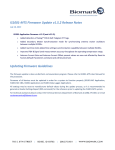
Control Panel Component Identification
LCD Display
Status Key
Back Key
Setup Key
Power On Indicator
Standby Key
Reset Key
Up/Down/Left/Right
Arrow Keys
System Ready
Indicator
Tag Detected
Indicator
Front View of the FS2020™
1.
Display: LCD graphical display.
2.
Status Key: Used to check the current status of the transceiver parameter settings.
3.
Setup Key: Used to change the transceiver parameter settings.
4.
Standby Key: Places the transceiver into standby mode.
5.
Up/Down/Left/Right Arrow Keys: Used to navigate through the transceiver menus.
6.
Back Key: Moves the display to the previous menu.
7.
Power On Indicator: This green LED glows solid when power is turned on to the unit.
8.
Reset Button: Resets the transceiver.
9.
System Ready Indicator: This yellow LED indicator slowly flashes as the system powers
up, then when transceiver is in scan mode either glows solid (if only FDX-B detection
enabled) or flickers rapidly (if HDX detection enabled).
10. Tag Detected Indicator: This red LED indicator flashes each time a tag ID is successfully
decoded.
FS2020 User Manual
3
Product Description
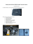
Port Identification
Sync In Port
Fiber Optic
Transmit Port
(remote port)
Fiber Optic
Receive Port
(remote port)
Ethernet Port
(remote port)
USB Port
(local port)
Antenna
Port
Gate Out Port
Sync Out Port
Bottom View of the FS2020
Antenna Port: Used to connect the transceiver to an RFID antenna.
Pins assignment:
•
Pin 1 – Antenna -
•
Pin 6 – Shield
•
Pin 7 – Antenna +
Sync In Port: Used to synchronize with another transceiver by receiving the other unit’s
antenna exciter clock signal.
Pins assignment:
•
Pin 1 – Reference (0V)
•
Pin 3 – RX +
•
Pin 4 – Shield
•
Pin 6 – RX -
Sync Out Port: Used to synchronize the transceiver with another unit by feeding the
transceiver’s antenna exciter clock signal to the other unit’s Sync In port.
Pins assignment:
4
•
Pin 4 – Shield
•
Pin 5 – TX +
•
Pin 7 – Reference (0V)
•
Pin 8 – TX FS2020 User Manual
Product Description
Gate Out Port: This is an auxiliary port that is used for triggering a site-specific action (such as
moving a gate within a flume) whenever a tag is detected. This port operation depends on the
Detection Unique Mode setting and is similar to the transceiver buzzer operation, except it is not
triggered by VTT detection. Each time a tag ID is detected and satisfied Detection Unique Mode
criteria the internal semiconductor switch is closed for 15 milliseconds.
Pins assignment:
•
Pin 1 – Switch +
•
Pin 2 – Switch -
•
Pin 4 – Shield
Fiber Optic Transmit Port (remote communication port): Used to transmit data to a remote
device through a fiber optic network.
Fiber Optic Receive Port (remote communication port): Used to receive data from a remote
device through a fiber optic network.
Ethernet Port (remote communication port): Used to monitor and operate the transceiver
from a remote location through a local area network (LAN).
USB Port (local communication port): Used to monitor and operate the transceiver from a
local device such as a laptop computer.
FS2020 User Manual
5
Product Description
Major Internal Hardware Components
Backup
Battery for
Memory and
Real-Time Clock
DC Power
Supply
AC Power
Entry Module
Mother Board
Antenna
Interface Board
6
Remote
Communication
Board
FS2020 User Manual
Product Description
DC Power Supply
The DC Power Supply converts 120-240V AC into adjustable 10-16.5V DC. This DC voltage is
used as Mother Board input voltage, specifically Antenna Exciter input voltage, which in turn is
converted into antenna current and antenna output power (antenna magnetic field strength).
DC Voltage
Status LED
DC Voltage
Adjustment
FS2020 User Manual
7
Product Description
Mother Board
The Mother Board is the main module of the transceiver. It contains all major functional
segments of the circuitry as well as input fuse, main tuning capacitors bank (manually and
electronically selectable), Virtual Tag signal level adjustment, and FDX-B and HDX signals
receivers’ adjustments.
Memory & RealTime Clock Backup
Battery Attachment
Buzzer
FDX-B Filters
Frequency
Response
Adjustments
Low-pass Filter
Adjustment
Virtual Tag
Signal Level
Adjustment
Manually
Selectable
Tuning
Capacitors
Jumpers
HDX Receiver
Adjustment
FDX-B Receiver
Adjustment
Sync Out
Termination
Jumper
Fuse
Sync In
Termination
Jumper
8
FS2020 User Manual
Product Description
User Interface Board
The User Interface Board incorporates the graphic LCD and the keypad interface. There are no
adjustments on this board.
FS2020 User Manual
9
Product Description
Antenna Interface Board
The Antenna Interface Board incorporates an additional bank of manually selectable tuning
capacitors that are connected in series with the main tuning capacitors bank on the Mother
Board. The Antenna Tuning Board contains five jumpers: the four jumpers on the left (SP1-SP4)
control the four associated capacitors located directly above the jumpers; the rightmost jumper
(SP5) is a bypass that disables these four capacitors. This bank typically should be used for
tuning an antenna that does not have any additional capacitors connected in series directly to its
coil.
Note: The need for using these capacitors depends not only on the antenna inductance, but
also on the capacitors setting at the antenna and the properties of the antenna cable.
Manually
Selectable
Tuning
Capacitors
Jumpers
10
Capacitors
Bypass Jumper
FS2020 User Manual
Product Description
Remote Communication Board
The Remote Communication Board incorporates the Ethernet and fiber optic communication
interface. It contains two jumpers that enable the Ethernet and the Fiber Optic ports. To disable
one of the ports (for example, to save on power consumption), remove the corresponding
jumper.
Ethernet
Module
Ethernet Module
MAC Address
Ethernet Port
Jumper
Fiber Optic Port
Jumper
FS2020 User Manual
11
Installation and System Configuration
Installation and System Configuration
Installing and Powering Up the Transceiver
1. Remove transceiver and all items from the shipping carton.
2. Check for correct content.
3. Locate an area to mount the transceiver.
The transceiver is designed for indoor use or installation into a NEMA 4 cabinet. It must be
mounted on a medium or high density vertical surface (such as wood, metal, concrete, etc.)
using ¼ inch bolts or screws within six feet of a grounded AC power source, away from
direct sun light and away from any water. Use the included mounting template to establish
the proper mounting holes’ locations.
Do not position the transceiver in a location that is difficult to reach or operate.
4. Use the four mounting brackets on each corner to mount the transceiver.
The hardware required to mount the transceiver at the site is not included.
5. Verify that transceiver power switch located on the AC power entry module on the right side
of the transceiver is in off position (“0”) and then install the power cord.
The power cord plugs into the AC power entry module. Make sure the transceiver is properly
grounded.
6. Connect the antenna cable to the antenna port on the transceiver.
After plugging the antenna cable into the antenna port, twist the locking ring to secure the
cable in place.
For instructions on tuning the antenna, see page 13.
X
X
7. Connect the transceiver to a local computer and/or to your network.
For instructions on establishing a connection with the transceiver, see page 40.
X
X
8. (Optional) If you are using multiple transceivers, install the synchronization cables.
For instructions on how to synchronize multiple transceivers, see page 18.
X
X
9. (Optional) If you have a device that will perform a site-specific action (such as moving a gate
within a flume) whenever a tag is detected, attach the device cable to the Gate Out port.
10. Make sure that all tuning jumpers on the Mother Board and on the Antenna Interface Board
are installed.
11. Toggle the power switch to on position (“I”).
The main screen is displayed. See page 21 for details.
X
12
X
FS2020 User Manual
Installation and System Configuration
Tuning the Antenna
Coarse-tuning the Antenna
The antenna tuning procedure should be performed after the initial installation of the
transceiver. The transceiver incorporates a total of eight manually selectable tuning capacitors
for coarse-tuning and six electronically selectable capacitors for fine-tuning the antenna. The
capacitors are split into two banks:
The main bank is located on the Mother Board and consists of four manually selectable
and six electronically selectable tuning capacitors. They provide a total tuning
capacitance ranging from 10nF to 128.9nF.
The secondary bank is located on the Antenna Interface Board and consists of 4
manually selectable tuning capacitors. This bank is connected in series with the main
bank and is used to reduce the total tuning capacitance, ranging in this case from 0.9nF
to 15.7nF. This bank typically should be used for tuning an antenna that does not have
any additional capacitors connected in series directly to its coil. This bank can be
switched out of the circuitry (shortened) using jumper SP5, which is located on the
Antenna Interface Board.
The coarse tuning procedure is as follows:
Note: Make sure that all the steps from installation procedure have been completed before
tuning the antenna.
When the transceiver powers up it performs a quick auto-tuning process that determines if the
antenna is connected to the transceiver and if it can be tuned using the six electronically
selectable tuning capacitors.
If the antenna is successfully tuned a confirmation message will be displayed and the
selected dynamic capacitors setting will be reported to the enabled communication ports.
In this case you can skip this section and proceed to Fine Tuning the Antenna on
page 14.
X
X
If the auto-tuning process fails an alarm is sent to the enabled communication ports and
one of the following messages will be displayed.
1. If NO ANTENNA CONNECTED is displayed, check the antenna for the proper connection
and antenna integrity. Also, note that if the antenna is too far out of tuning range the
transceiver may not detect any current in the antenna and will generate this message as
well. In this case decrease the tuning capacitance of the transceiver and re-tune the
antenna (see Step 3).
2. If INC TUN CAPACITANCE is displayed and if all tuning jumpers are installed (and they are
all installed when the transceiver is shipped), increase the capacitance at the antenna or
increase the antenna inductance.
3. If DEC TUN CAPACITANCE is displayed, decrease the total tuning capacitance by
removing one or more of the tuning capacitors jumpers on the Mother Board (see page 8).
Use the diagram below to determine the next lowest capacitance jumper setting. (This
diagram is located on the inside of the transceiver enclosure door).
X
X
Note: To avoid possible injury or damage to the equipment it is recommended that you
switch the transceiver to standby mode or switch off power before moving the tuning
capacitors jumpers.
FS2020 User Manual
13
Installation and System Configuration
4. Reinitiate the auto-tuning process either by powering the transceiver back on or by selecting
Setup > Antenna > Antenna Full Tune.
5. Repeat Steps 1 – 4 until either the antenna is successfully tuned or until all the tuning
jumpers on the Mother Board are removed.
If the antenna is successfully tuned you can skip the remainder of this section and
proceed to Fine Tuning the Antenna on page 14.
X
X
If you have removed all the tuning jumpers on the Mother Board and the antenna is
still not tuned, proceed to Step 6.
6. If all tuning jumpers on the Mother Board are removed and DEC TUN CAPACITANCE is still
being displayed, switch in the secondary tuning capacitors bank by removing jumper SP5 on
the Antenna Interface Board (see page 10).
X
X
7. Reinstall all tuning jumpers on the Mother Board and reinitiate the auto-tuning process.
8. Repeat Steps 1 – 5 until all tuning jumpers on the Mother Board are removed.
9. If all tuning jumpers on the Mother Board are once again removed and DEC TUN
CAPACITANCE is still being displayed, decrease the total tuning capacitance by removing
one or more of the tuning capacitors jumpers on the Antenna Interface Board.
Use the same diagram (above) to determine the next lowest capacitance jumper setting.
10. Repeat Steps 1 – 5 until the antenna is tuned or until all the tuning jumpers on the Mother
Board and the Antenna Interface Board are removed.
11. If all tuning jumpers on the Mother Board and the Antenna Interface Board are removed and
DEC TUN CAPACITANCE is still being displayed, decrease capacitance at the antenna or
decrease antenna inductance and repeat the tuning process.
This concludes the antenna coarse-tuning process. During this process the manually switched
capacitors setting is determined for the antenna so that it is within the tuning range of the
electronically switched capacitors.
Fine-tuning the Antenna and Dynamic Tuning
The next step is to perform the antenna full tuning process. You do this by selecting Setup >
Antenna > Antenna Full Tune.
During this process the transceiver goes through every possible electronically switched
capacitors setting combination to tune the antenna more precisely. There are total of 64 setting
combinations (0 to 63) providing a tuning range from 10nF to 19.8nF.
Setting “0” means all capacitors are switched off and the tuning value is at a
minimum – 10nF
Setting “63” means all capacitors are switched in and the tuning value is at a
maximum – 19.8nF.
The transceiver will select the final capacitors setting that produced the highest antenna current.
At the same time the antenna signal phase measurement is taken and saved as the tuning
target phase value. This value will be used by Dynamic Tuning (when enabled) to track any
14
FS2020 User Manual
Installation and System Configuration
changes to the environment (such as water depth, ambient temperature, foreign objects
presence, components deterioration, etc.) that resulted in antenna de-tuning and to adjust
capacitors setting accordingly to re-tune the antenna. When the antenna de-tunes it means its
signal phase has deviated from the target value. Dynamic tuning tracks this phase deviation to
determine when and what adjustments to make to the capacitors setting to return the phase
value to the target value and in turn re-tune the antenna. The adjustments are done gradually,
so there is no interruption of tag detection. If there is any tag detection interruption it is due to
the antenna being out of tune until dynamic tuning re-adjusts it.
Dynamic tuning has a finite range, so not all changes in antenna tuning can be recovered using
digitally switched capacitors. Considering this, it is recommended to adjust the manually
switched capacitors setting so that the final dynamic tuning capacitors setting is as close to the
mid-range as possible.
There are customizable alarms available that can notify you in advance of approaching the limit
of the dynamic tuning range. Alarms will also notify you if the antenna is out of range and they
will suggest the direction of changes to make to the manually switched capacitors setting.
Setting the Antenna Dynamic Tuning Responsiveness
The responsiveness (sensitivity) of the Dynamic Tuning can be adjusted by changing the
Antenna Dynamic Tuning Phase Deviation Threshold value. The Dynamic Tuning will not
attempt any tuning capacitance adjustments until the phase deviation value does not exceed the
threshold setting in either direction. This value should be set smaller for high Q systems where
smaller antenna tuning changes can result in larger detection degradation. And vice versa: for
low Q systems where bigger tuning changes would not cause large detection losses or for the
systems with rapid and frequent conditions changes the threshold setting could be set higher to
reduce the unnecessary Dynamic Tuning activity. The threshold value should not be set too low
to ensure stable Dynamic Tuning operation.
FS2020 User Manual
15
Installation and System Configuration
Fine-tuning the Transceiver
Each transceiver undergoes a thorough optimization and testing process at the factory and is
ready for operation right out of the box. But sometimes, depending on the installation
environment and the properties of the antenna and antenna cable, the transceiver might require
slight adjustments for the best performance.
Care should be taken to avoid any injuries or damage to the transceiver. The present settings of
all adjustments should be noted and recorded for backup.
The following procedure will help guide qualified personnel in the steps necessary to fine-tune
an FS2020 Transceiver.
Tools Required
Nonconductive potentiometer adjustment tool or small flat blade screwdriver.
Oscilloscope with the voltage probes (if available).
FDX-B Signal Receiver Optimization
To trace the progress of this procedure a real FDX-B tag or a Virtual Tag should be used in
conjunction with Detection Efficiency Test or audible sound of the buzzer.
For more information about the Detection Efficiency Test see page 30.
X
X
1. If a real FDX-B tag is used:
Enable the Detection Efficiency Test by selecting Setup > Detection > Det. Efficiency
Test = On. Return to the main menu and note the test results.
Place the tag in the antenna field and slowly move it away until the detection rate is
reduced to approximately one or two reads per second.
If the Virtual Tag is used:
Enable the virtual test tag by selecting Setup > Detection > Virtual Tag Test = On.
Detection efficiency test is enabled automatically at the same time. Return to main menu
and note the test results.
Adjust the VTT potentiometer RV8 on the Mother Board to reduce the virtual tag signal
level until the detection rate is reduced to approximately one or two reads per second.
2. Fine-tune the receiver by adjusting the FDX variable capacitor CV2 on the Mother Board to
improve the detection rate (more reads per second).
16
FS2020 User Manual
Installation and System Configuration
3. Optimize the frequency response of the FDX-B filters by adjusting the two frequency
potentiometers RV2 and RV3. These potentiometers are used to equalize the amplitudes of
the 2 KHz and 4 KHz signals:
a. If available, attach an oscilloscope voltage probe to the filter output BFLTR test point
TP2 on the Mother Board. The oscilloscope channel needs to be AC coupled. Adjust
the scope time domain so that the signal waveform can be viewed clearly (0.5
msec/div).
b. Adjust potentiometers RV2 and RV3 one-by-one to improve the detection rate and to
improve the signal shape.
c. After this adjustment, the detection at short distances needs to be verified by putting
a tag as close as possible to the antenna coil or by increasing the Virtual Tag level to
the maximum (turn RV8 all the way clockwise). Make sure there is no interruption in
the detection and that the signal shape is not distorted.
FDXB Filter
Output Test Point
Potentiometers/FDX-B
Filters Frequency Response
Adjustments
Ground Test Point
Potentiometer/
Low-pass Filter
Adjustment
4. Repeat Steps 2 and 3 while moving the tag further away from the antenna or by reducing
the Virtual Tag level until no improvement to the detection rate can be achieved.
5. Run the Antenna Full Tune process by selecting Setup > Antenna > Antenna Full Tune.
6. Sometimes better performance can be achieved when the antenna is slightly de-tuned by
manually changing the Antenna Dynamic Tuning Target Phase value. This is done by
selecting Setup > Antenna > Tuning Target Phase. Adjust the target phase value in small
increments by up to 50 points total in both directions to improve detection rate and increase
the read range.
7. Adjust potentiometer RV4 to improve the detection rate and to improve the signal shape.
8. Repeat steps 1 through 7 to verify the improvements and to possibly gain more.
FS2020 User Manual
17
Installation and System Configuration
HDX Signal Receiver Optimization
To trace the progress of this procedure a real HDX tag must be used in conjunction with the
Detection Efficiency Test or with the audible sound of the buzzer.
1. Enable HDX detection by selecting Setup > Detection > HDX Detection = On.
2. Enable the Detection Efficiency Test by selecting Setup > Detection > Det. Efficiency Test
= On.
Return to main menu and note the test results.
3. Place the tag in the antenna field and slowly move it away until the detection rate is reduced
to approximately one or two reads per second.
4. Fine-tune the receiver by adjusting the HDX variable capacitor CV1 on the Mother Board to
improve detection rate (more reads per second).
Repeat steps 3 and 4 until no further improvement to the detection rate can be achieved.
Synchronizing Multiple Transceivers
If your location contains more than one antenna/transceiver combination, and if the antennas
are located in close proximity to one another, you will likely have to synchronize the transceivers
in order to avoid antenna phase and noise issues. This section explains why it is necessary to
synchronize the transceivers, shows how to cable the transceivers together, and describes how
to configure synchronization parameters on each transceiver.
Synchronization is done by synchronizing the Antenna Exciter clock of each transceiver through
hardwired twisted-pair interface. The transceivers are connected in a daisy chain configuration,
where the synchronization output (Sync Out Port) is connected to the synchronization input
(Sync In Port) of the next reader and synchronization input is connected to the output of the
previous reader. The first transceiver does not require the synchronization input as it is the
source of the synchronization signal. The last transceiver does not have anything connected to
its output. Synchronization input signal is used by each transceiver’s Antenna Exciter and also
is passed through to the synchronization output.
Local
oscillator
(134.2kHz)
Sync In Antenna Sync Out
Antenna
Local
oscillator
(134.2kHz)
Sync In Antenna Sync Out
Local
oscillator
(134.2kHz)
Sync In Antenna Sync Out
Antenna
To next reader
Antenna
Synchronization network
Use a 4-conductor, two twisted pairs, 18-22AWG wire, shielded cable:
•
•
18
Use the conductors of one pair to connect TX + to RX + and TX - to RX Use the conductors of the second pair as the signal reference connection
FS2020 User Manual
•
Installation and System Configuration
Use the cable shield drain wire to connect to the shield pins
If using a single twisted pair, 18-22AWG wire, shielded cable, a cable shield drain wire should
be used as a signal reference conductor.
Synchronization Wiring Diagram
Master/Slave Concept
Each transceiver can be configured to operate in one of the four synchronization modes that will
define this unit’s role in the chain and its behavior:
Master Mode: The transceiver uses its own Antenna Exciter clock as the source of the
synchronization signal and transmits it to its synchronization output. Synchronization input is
disabled. If the unit is put in standby mode its synchronization output signal is disabled. The
first transceiver in the chain must be configured as a Master.
Slave Mode: The transceiver uses the synchronization input signal for its Antenna Exciter
and also transmits it to its output. The synchronization output signal is still enabled if the
transceiver is put in standby mode. If the synchronization input is not present its Antenna
Exciter and synchronization output are disabled.
Secondary Master Mode: If the transceiver detects a synchronization signal on its input it
acts as a Slave. It uses the input signal for its Antenna Exciter and also transmits it to its
output, even when put in standby mode. If the synchronization input is not present the
transceiver acts as a Master and uses its own Antenna Exciter clock as the source of the
synchronization signal and transmits it to its synchronization output. If the unit is put in
standby mode its synchronization output signal is disabled. If at any point the
synchronization signal is detected on its input, the transceiver will switch back to being a
Slave. This mode should be selected for transceivers dedicated as synchronization signal
back up source.
Standalone Mode: The transceiver uses its own Antenna Exciter clock; its synchronization
input and output are disabled.
How to Configure the Transceivers for Sync Mode
1. Configure the first transceiver in the chain as the master
Setup > Reader > Sync Mode = Master
2. Configure all other transceivers in the chain as secondary masters or slaves
Setup > Reader > Sync Mode = Sec. Master or Slave
FS2020 User Manual
19
Installation and System Configuration
If the Synchronization Signal is Lost
If the synchronization signal is lost, any transceiver that is set as a secondary master will
attempt to assume the master role. To prevent multiple transceivers from becoming the master,
each secondary master will continually monitor for a synchronization input signal from an
upstream transceiver. If a transceiver receives a synchronization input signal it will stop
attempting to assume the master role and will revert to its slave role. So the secondary master
that is first in line (furthest upstream in the chain) will ultimately assume the role of the master.
20
FS2020 User Manual
Understanding the Main Menu
Understanding the Main
Menu
When you power on the transceiver the
main menu is displayed.
There are three primary areas on the main
menu.
•
The top row is a status bar that displays
a number of status indicators.
o
The first field displays the antenna
current in Ampers peak-to-peak.
o
The second field is a dual-use field.
If a tag is present it displays the
signal strength of the tag. If a tag is
not present it displays the signal
noise level of the antenna.
o
The third field displays the detected
tag ID count. This figure represents
the total number of tag IDs that were
detected by the transceiver since the
last reset of the detection counter
(via the Power/Reset key or via
Setup > Detection > Tag Counter >
Reset).
The status bar will also flash “ALARMS”
if any alarms are presently active.
•
The large middle area displays
information about the last tag detected
by the reader. The first line displays the
manufacturer ID or country code of the
tag. The second line displays the unique
tag ID.
This area will also display the
transceiver operating mode percent and
the results of the detection efficiency test
(if enabled).
FS2020 User Manual
Main Menu in Scan Mode
Main Menu in Standby Mode
•
The bottom row contains the following
keys:
o
Status: Used to access the Status
menus. See page 23.
X
o
X
Setup: Used to access the Setup
menus. See page 27.
X
o
X
Scan / Stby: Toggles the transceiver
between Scan mode and Standby
mode. When in Standby mode, the
antenna
exciter
is
disabled.
21
How To Scan For Tags
How To Scan For Tags
•
The transceiver automatically starts in Scan
mode after a power on or a reset and will
immediately begin scanning for tags.
Where detected tags are stored and where
they are sent depends on how the
transceiver is configured.
•
All new tag IDs will be stored in memory
(this is not configurable).
•
Virtual test tag IDs will be stored in
memory if Setup > Memory > Store
Virtual Tag = On.
•
New tag IDs will be automatically sent to
the
remote
communication
ports
(Ethernet and fiber optic).
•
New tag IDs may be sent to the USB
port if Setup > Communication > Send
Tags to Local Port = On (see page 29).
X
•
X
Duplicate tag IDs (the same tag ID
detected several times) may or may not
be recorded depending on how Setup >
Detection > Unique Mode is configured
(see page 30).
X
X
How to View
Detected Tags
and
Capture
•
To view the number of tags that have
been detected by the transceiver, see
the top-right field on the main menu.
•
To view the number of tags stored in
memory, select Status > Time, Mem. &
Comm. > Stored Tag Count.
•
Detected tag IDs are always sent to the
remote ports (Ethernet and Fiber Optic).
Any communications program that is
monitoring these ports will receive the
tag data. See page 43 for information on
using the remote ports.
X
•
X
Detected tag IDs can optionally be sent
to the local USB port if Setup >
Communication > Send Tags to Local
Port = On. Any communications
program that is monitoring this port will
receive the tag data. See page 42 for
information on using the USB port.
X
22
To download tag IDs that are stored in
memory, select Setup > Memory >
Download
Memory.
Any
communications
program
that
is
monitoring the remote ports (Ethernet
and Fiber Optic) will receive the tag
data. The tags will also be downloaded
to the local port if Setup >
Communication > Send Tags to Local
Port = On.
X
FS2020 User Manual
Status Menu
Status Menu
Pressing the Status Key on the main menu
displays the Status menu. The Status menu
contains four sub-menu items:
Diagnostics
Time, Mem. & Comm. (see page 24)
X
X
Reader Settings (see page 25)
X
X
Device Info (see page 26)
X
X
Status Menu with Diagnostics
Highlighted
Diagnostics Menu
Press the Status key on the main menu and
then select Diagnostics.
Available information:
•
Input Voltage: Displays the present
input voltage, in volts.
•
Exciter Voltage: Displays the antenna
exciter voltage, in volts.
•
Antenna Current: Displays the present
antenna current, in amperes peak-topeak.
•
Signal Level: Displays the present
FDXB signal level (0 – 100%).
•
Tuning Capacitance: Displays the
present dynamic tuning capacitance
setting. Valid values are 0 – 63.
•
Tuning Relative Phase: Displays the
present antenna tuning target phase
minus the present measured phase.
•
Reader Temperature: Displays the
present internal temperature of the
transceiver, in degrees Celcius.
•
Backup Battery: Displays the present
status of the backup battery, in Volts.
The battery protects the internal clock
and memory data.
•
Virtual Tag Level: Displays the present
virtual tag potentiometer setting (0 –
100%).
•
Alarms: Displays the list of all currently
active alarms.
FS2020 User Manual
Diagnostics Menu
23
Status Menu
Time, Memory &
Communication Menu
Press the Status key on the main menu and
then select Time, Mem. & Comm.
Available information:
•
Reader Date: Displays the present date
using a mm/dd/yyyy format.
To change this setting: Setup > Reader
> System Date.
•
Reader Time: Displays the present time
using a hh:mm:ss format.
Status Menu with Time, Mem, & Comm.
Highlighted
To change this setting: Setup > Reader
> System Time.
•
Stored Tags Count: Displays the
number of tag IDs currently stored in
memory.
To download or erase memory: Setup >
Memory.
•
Free Memory: Displays the percentage
of available tag ID memory space. If
memory becomes completely full the
oldest tag will be overwritten by the new
tag.
Time, Mem. & Comm. Menu
To download or erase memory: Setup >
Memory.
•
Remote Port Protocol: Displays the
communication protocol being used on
the remote port (ASCII or BPA).
To change this setting: Setup >
Communication > Remote Port Protocol.
•
Local Port Speed: Displays the speed
setting of the local communication port.
To change this setting: Setup
Communication > Local Port Speed.
•
>
Tag ID Display Format: Displays the
format to use when displaying tag IDs
(hexadecimal or decimal).
To change this setting: Setup > Reader
> Tag Display Format.
24
FS2020 User Manual
Status Menu
Reader Settings Menu
Press the Status key on the main menu and
then select Reader Settings.
Available information:
•
Reader ID: Displays the hexadecimal ID
of this transceiver.
To change this setting: Setup > Reader
> Reader ID.
•
Antenna Q: Displays the antenna
quality factor setting (Low or High).
Status Menu with Reader Settings
Highlighted
To change this setting: Setup > Antenna
> Antenna Q.
•
Reader Initiation Delay: Displays if the
transceiver is configured to delay
transmission
of
all
automatic
diagnostics. The delay is computed by
multiplying the Reader ID by 1 second.
To change this setting: Setup > Reader
> Reader Initiation Delay.
•
Sync Mode: Displays the present
synchronous mode setting (Master, Sec
Master, Slave, or Standalone). For
detailed information on synchronizing
multiple transceivers, see page 18.
X
X
To change this setting: Setup > Reader
> Sync Mode.
•
•
•
Sync Signal: Indicates if a cable is
connected to the Sync In port and a
synchronization signal is present.
FDXB Det. Sensitivity: Displays the
present sensitivity (range) setting.
To change this setting: Setup
Detection > FDXB Det. Sensitivity.
•
Reader Settings Menu
To change this setting:
Detection > HDX Detection.
Setup
To change this setting: Setup
Detection > Det. Unique Mode.
•
>
HDX Detection: Displays the present
HDX detection setting (On or Off)
>
Detection Unique Mode: Displays the
present detection unique mode setting
(Last 1, Last 5, Delay, or Off).
Detection Unique Delay: Displays the
number of minutes to delay the
reporting of unique tags.
To change this setting: Setup
Detection > Det. Unique Delay.
•
>
>
Dynamic Tuning: Displays the present
antenna dynamic tuning setting (On or
Off).
To change this setting: Setup > Antenna
> Dynamic Tuning.
FS2020 User Manual
25
Status Menu
Device Info Menu
Press the Status key on the main menu and
then select Device Info.
Available information:
•
Reader SN: Displays the Reader serial
number.
•
Application Version: Displays the
present application firmware version.
•
Boot Version: Displays the boot up
firmware version.
•
CPLD Version: Displays the CPU CPLD
(Complex Programmable Logic Device)
firmware version.
•
DSP Version: Displays the DSP (Digital
Signal Processing) firmware version.
Status Menu with Device Info Highlighted
Device Info Menu
26
FS2020 User Manual
Setup Menu
Setup Menu
Pressing the Setup key on the Main menu
displays the Setup menu. The Setup menu
contains eight sub-menu items:
Alarms
Antenna (see page 28)
X
X
Communication (see page 29)
X
X
Detection (see page 30)
X
Setup Menu with Alarms Highlighted
X
Measurements (see page 32)
X
X
Memory (see page 33)
X
X
Reader (see page 34)
X
X
Reports (see page 35)
X
X
Alarms Menu
Press the Setup key on the main menu and
then select Alarms.
Available parameters:
•
Current Low Alarm: Used to set the low
antenna current alarm threshold. Valid
values are 0.0A to 10.0A. Default is
1.0A.
Alarms Menu
•
Cap. Low Alarm: Used to set the
tuning capacitance low alarm. If the
transceiver dynamic tuning capacitors
setting becomes equal to or lower than
this limit, an alarm is sent. Valid values
are 0 – 31. Default is 0.
•
Alarm Unique Delay: Used to set the
alarm unique delay. Valid values are 0 –
3600 seconds.
A low antenna current may be caused by
an out-of-tune antenna, a bad antenna
or antenna connection, reader failure, or
an improper threshold setting.
•
Noise High Alarm: Used to set the
excessive noise level alarm threshold.
Valid values are 0 to 100%. Default is
50%.
A high noise level may indicate reader
deterioration (tuning or connection
problem, etc.)
•
Cap. High Alarm: Used to set the
tuning capacitance high alarm. If the
transceiver dynamic tuning capacitors
setting becomes equal to or greater than
this limit, an alarm will be sent. Valid
values are 32 – 63. Default is 63.
This specifies how long to wait before
rebroadcasting a persistent alarm. For
example, if Alarm Unique Delay = 60
and the capacitance low alarm is
triggered, the transceiver will wait 60
seconds before resending the alarm. If
the alarm condition clears and then
reappears, the new alarm will be sent
without delay.
Note: The Virtual Tag Test Failed alarm
is the exception and will not be
rebroadcast.
FS2020 User Manual
27
Setup Menu
Antenna Menu
Press the Setup key on the main menu and
then select Antenna.
To change an option, select it and then
press Change.
Available parameters:
•
Antenna Q: Used to set the antenna
quality factor. Valid values are Low or
High. Default is High.
Switching to Low will significantly reduce
the output power of the antenna. This
may be desirable if you are using a small
antenna and you want to reduce the
number of tag collisions due to fish
grouping.
Antenna Menu
•
Note: For users of older model
transceivers, Low is equivalent to
juvenile mode and High is equivalent to
adult mode.
•
This specifies how far the actual antenna
signal phase can deviate from the target
phase before the transceiver begins the
dynamic auto-tune process. During this
process
the
transceiver
adjusts
capacitance in an effort to return to the
target phase.
Dynamic Tuning: Used to set antenna
dynamic tuning to either On or Off.
Default is On.
Note: In low Q systems you might set
the Tuning Phase Deviation rather high
(40 – 50). In high Q systems requiring
more finely tuned antennas you might
set the deviation rather low (5 – 10). But
beware of setting the deviation value so
high that the transceiver is not making
any adjustments or so low that the
transceiver is not able to maintain the
tune point.
Dynamic Tuning automatically adjusts
the tuning capacitor settings to achieve
the desired target phase value.
•
Antenna Full Tune: Used to initiate a
full auto-tuning process of the antenna. It
is used to determine the optimum tuning
parameters. The process is as follows:
1. Checks if the antenna is present.
2. Performs a quick tune.
3. Performs a full tune by going thru all
64 possible electronically selectable
capacitor setting combinations to find
the maximum antenna current value.
The corresponding phase value
becomes the target phase value.
Tuning Phase Deviation: Used to set
the tuning phase deviation threshold.
Valid deviation values are 1 – 100.
Default is 10.
Tuning Capacitance: Used to set the
specific antenna tuning capacitance
level. Valid values are 0 – 63.
The full auto-tuning process will typically
take less than 10 seconds to complete.
•
28
Tuning Target Phase: Used to set or
adjust the tuning target phase. Valid
values are 0 – 1023.
FS2020 User Manual
Setup Menu
Communication Menu
Press the Setup key on the main menu and
then select Communication.
To change an option, select it and then
press Change.
Available options:
•
•
Remote Port Protocol: Sets the
protocol
used
on
the
remote
communication ports (Ethernet and fiber
optic). Valid options are ASCII or BPA
(Bonneville
Power
Administration).
Default is BPA.
Setup Menu with Communication
Highlighted
Local Port Speed: Sets the speed used
on the local USB communications port.
Valid options are 9600, 19200, 38400,
57600, or 115200. Default is 115200
Bd/s.
Note: Because the transceiver sends
data to both the local port and the
remote port at the same speed, lowering
the local port speed will affect the data
output speed on the remote port. The
recommendation is to use the highest
speed possible.
•
Send Alarms to Local Port: Specifies if
alarms are sent to the local USB port.
Valid options are either On or Off.
Default is Off.
•
Send Tags to Local Port: Specifies if
detected tag IDs sent to the local USB
port. Valid options are either On or Off.
Default is Off.
FS2020 User Manual
Communication Menu
29
Setup Menu
Detection Menu
Press the Setup key on the main menu and
then select Detection.
To change an option, select it and then
press Change.
Available options:
•
FDXB Det. Sensitivity: Adjusts the
range at which FDXB tags are detected.
Valid values are 20 – 100%. Default is
100%.
•
HDX Detection: Specifies if half duplex
detection is enabled. HDX tags will not
be detected if this option is disabled.
Valid values are On and Off. Default is
Off.
•
Tag Counter: Specifies if you want the
transceiver to keep a running count of
the tags it detects. Valid values are On,
Off, and Reset. Default is On.
Setup Menu with Detection Highlighted
The tag counter counts all detected tag
IDs regardless of the Unique Mode
setting.
•
Det. Efficiency Test: Enables the
detection efficiency test. This is used to
qualify the performance of the entire
system. Valid values are On and Off.
Default is Off.
Efficiency is calculated as a percentage
of the number of detections vs. the
maximum possible over two second
intervals. This test will work with physical
tags and with virtual test tags.
Detection Menu
o
Last 5: Tag ID is sent to
communication ports accompanied
by buzzer sound (if enabled) and
stored in memory only if it is
different from the previous five
detected dissimilar tag IDs.
o
Delay: Tag ID is sent to
communication ports accompanied
by buzzer sound (if enabled) and
stored in memory only if the
specified number of minutes have
passed since it was first detected
or if it is different from the previous
five detected dissimilar tag IDs.
Use either the Set delay key or
Det. Unique Delay to specify the
delay value.
o
Off: Disables unique mode. All tag
IDs are sent to communication
ports accompanied by buzzer
sound (if enabled) and stored in
memory.
Note:
This
parameter
will
be
automatically changed to On whenever
Setup > Detection > Virtual Test Tag =
On.
•
Det. Unique Mode: Specifies how the
tag ID is handled if it is detected multiple
times. Valid values are:
o
30
Last 1: Tag ID is sent to
communication ports accompanied
by buzzer sound (if enabled) and
stored in memory only if it is
different from the previously
detected tag ID. This is the default
value.
Note: Tag Detected LED flashes and
tag ID is displayed on LCD every time
FS2020 User Manual
Setup Menu
a tag is detected regardless of Det.
Unique Mode setting.
•
Det. Unique Delay: Specifies the delay
value for Unique Mode Delay. Valid
values are 1 – 1440 minutes. Default is
1 minute.
Note: In order for Det. Unique Delay to
be active Det. Unique Mode must be set
to Delay. When Det. Unique Mode is set
to Last 1 or Last 5 Det. Unique Delay
function is disabled.
•
•
Virtual Test Tag: The Virtual Test Tag
(VTT) is a feature designed to verify the
transceiver’s integrity and sensitivity. It
generates an ISO FDX-B tag signal at
selectable signal levels and can be
activated in the following manner:
o
Automatically if Auto. VTT Delay is
set to a non-zero value. The test is
performed
at
user-selectable
intervals.
o
Manually if Virtual Test Tag =
Single Shot. The test is initiated for
100 milliseconds.
o
Manually if Virtual Test Tag = On.
The test is initiated continuously and
works in conjunction with detection
efficiency test. Detection Efficiency
Test is activated automatically when
Virtual Test Tag = On.
Auto. VTT Delay: Used to set the
automatic virtual test tag single shot
activation delay. The delay can be set
from 0 (disabled) to 1440 minutes (24
hours). When the delay expires, if a real
PIT tag is not present in the FS2020
antenna field then the virtual test tag will
be activated for 100 milliseconds. This
test is done in order to verify that the
reader is operating properly especially
during extended periods when no PIT
tags are present.
FS2020 User Manual
31
Setup Menu
Measurements Menu
Press the Setup key on the main screen
and then select Measurements.
To change an option, select it and then
press Change.
Available options:
•
Current Gain: Used to set the antenna
current measurement gain. This value is
used to calibrate the antenna current
peak-to-peak
measurement.
Valid
values are 1 – 400000. Default is 1700.
•
Current Offset: Used to set
the
antenna current measurement offset.
Valid values are from -400000 to
400000. Default is 50.
•
Noise Gain: Used to set the noise gain
or a tag signal measurement gain. This
value is used to calibrate noise level or
tag signal level measurement. Valid
values are 1 – 10,000. Default is 3000.
Noise measurement corresponds to
peak-to-peak value of a signal at FDX-B
receiver output on the Mother Board,
meaning that if signal is 5V peak-to-peak
(maximum
possible),
noise
level
measurement should be 100%. If the
output signal is 200mV peak-to-peak,
noise level measurement should be 4%.
Setup Menu with Measurements
Highlighted
Measurements Menu
If a real tag is present the measurement
is treated as the tag signal level.
32
FS2020 User Manual
Setup Menu
Memory Menu
Press the Setup key on the main screen
and then select Memory.
To change an option, select it and then
press Change.
Available options:
•
Download Memory: Initiates the
download of all tag IDs and short status
reports contained in the transceiver’s
memory. Tag data is sent to the remote
ports (Ethernet and fiber optic) and will
also be sent to the local port (USB) if
Setup > Communication > Send Tags
to Local Port = On.
Setup Menu with Memory Highlighted
The transceiver memory is NOT erased
during the download process.
•
Erase Memory: Permanently erases all
tag IDs and short status reports
contained in the transceiver’s memory. A
warnng message is displayed asking
you to confirm this action.
The recommendation is to download the
contents of memory to another computer
or storage device before erasing
memory.
•
Memory Menu
Store Virtual Tag: Specifies if virtual
test tag IDs will be stored in memory.
Valid values are On and Off. Default is
On.
FS2020 User Manual
33
Setup Menu
Reader Menu
Press the Setup key on the main screen
and then select Reader.
To change an option, select it and then
press Change.
Available options:
•
Reader ID: Sets the unique ID for this
transceiver. The ID is a hexadecimal
value in the range 00 – FF. Default is 01.
•
Reader Date: Sets the present date.
The date is specified as mm/dd/yyyy.
•
Reader Time: Sets the present time.
The time is specified using a hh:mm:ss
(24 hour) format.
•
Reader Initiation Delay: Specifies if the
transceiver will delay all automatic
diagnostics (such as status report, noise
report, and VTT) at startup time. All
other functionalities, including tag
detection, are not delayed. Valid values
are On and Off. Default is On.
Setup Menu with Reader Highlighted
Reader Menu
The delay time is calculated by
multiplying the Reader ID by 1 second.
•
Sync Mode: Sets the transceiver
synchronization mode. Valid values are
Master, Sec. Master, Slave, and Stand
Alone. Default is Sec. Master. See
page 18 for details on multiple reader
configurations.
X
•
•
•
34
•
Set Default Parameters: Resets the
Setup paramenters to their default
values. A warning message will prompt
you to confirm this action.
X
Tag ID Display Format: Specifies the
format to use when displaying detected
tag IDs. Valid values are Decimal and
Hexadecimal. Default is Hexadecimal.
Reader Beeper: Specifies if the
transceiver will issue an audible beep
when a tag is detected. Valid values are
On and Off. Default is Off.
Display Backlight: Specifies if the
transceiver’s backlight will be used. Valid
values are On, Off, and Saving. When in
Saving mode, the backlight will turn off
after 10 seconds of inactivity and will
turn back on when a tag is detected or
when a key is pressed.
This will not clear memory or the
detection counter. In addition, the
following parameters are excluded:
o
o
o
o
o
o
o
o
o
o
o
Antenna Q
Antenna Dynamic Tuning Target
Phase
Antenna Dynamic Tuning Phase
Deviation Threshold
Current Measurement Gain
Current Measurement Offset
FDXB Det. Sensitivity
Noise Measurement Gain
Reader ID, Reader Date, Reader
Time
Reader Initiation Delay
Reader Synchronization Mode
Remote
Communication
Port
Protocol
FS2020 User Manual
Setup Menu
Reports Menu
Press the Setup key on the main screen
and then select Reports.
To send a report, select it and then press
Ok. The report information is sent to the
remote ports (Ethernet and fiber optic) and
will also be sent to the local port (USB) if
Setup > Communication > Send Tags to
Local Port = On. See pages 42 - 44 for
instructions on configuring and using these
ports.
X
X
X
All reports can also be generated by issuing
commands from a local or remote
workstation. See page 48 for details.
X
Reports Menu
•
Noise Report Delay: Specifies how
often to automatically send the Noise
Status report. Valid values are 0
(disabled) to 1440 minutes (once every
24 hours). Default is 0.
•
Report Full Status: Immediately
generates and sends a Full Status
Report. This report contains vital
transceiver configuration settings and
diagnostic data.
X
Available options:
•
•
•
Report Date & Time: Immediately
generates and sends a Date & Time
Report. The report contains the present
date and time set on the transceiver.
Report Detection Count: Immediately
generates and sends a Detection Count
Report. The report contains the number
of tags detected by the transceiver.
Report Firm. Versions: Immediately
generates and sends a Firmware
Version Report. The report contains the
transceiver serial number and a list of all
firmware versions (Boot, Application,
CPLDs, and DSP).
•
Report Memory Status: Immediately
generates and sends a Memory Status
Report. The report contains the number
of tag IDs and the number of short status
reports stored in memory and also the
amount of available memory.
•
Report Noise Status: Immediately
generates and sends a Noise Status
report. The report provides noise
statistics such as average and peak
noise measurement values.
See page 51 for details.
X
•
X
Status Report Delay: Specifies how
often to automatically send the Full
Status report. Valid values are 0
(disabled) to 1440 minutes (once every
24 hours). Default is 180.
Short versions of automatic status
reports (containing critical dynamic
diagnostic parameters) are stored in
memory (up to 151 reports). The
following format is used: fixed-length
string of parameters separated by
comas, with placeholders for 5 3-letter
alarm message codes at the end:
NNN,param1,param2,param3,…,param1
6,X,X,X,X,X
“NNN” – stored status report number
“X” – placeholder for an alarm message
code.
See page 52 for details.
X
FS2020 User Manual
X
35
Menu Structure
Menu Structure
Menus and Parameters
Menu
Status
36
Sub Menu
Sub Menu
Settings
Diagnostics
Display:
Input Voltage
Exciter Voltage
Antenna Current
Signal Level
Tuning Capacitance
Relative Phase
Reader Temperature
Backup Battery
Virtual Tag Level
Alarms
Time, Mem. &
Comm.
Display:
Reader Date
Reader Time
Stored Tags Counter
Free Memory
Remote Port Protocol
Local Port Speed
Send Alarms to Local Port
Send Tags to Local Port
Tag ID Display Format
Reader Settings
Display:
Reader ID
Antenna Q
Reader Initiation Delay
Sync Mode
Sync Signal
FDXB Det. Sensitivity
HDX Detection
Detection Unique Mode
Detection Unique Delay
Dynamic Tuning
Device Info
Display:
Reader SN (Reader Serial Number)
Application Version
Boot Version
CPLD Version
DSP Version
FS2020 User Manual
Menu Structure
Setup
Alarms
Antenna
Communication
Detection
FS2020 User Manual
Current Low
Alarm
Set Current Low Alarm Threshold in Amperes
{0.0-10.0} (Default: 1.0)
Noise High
Alarm
Set Noise High Alarm Threshold in Percents
{0-100} (Default: 50)
Cap. High
Alarm
Set Tuning Capacitance High Alarm
Threshold {32-63} (Default: 63)
Cap. Low Alarm
Set Tuning Capacitance Low Alarm
Threshold {0-31} (Default: 0)
Alarm Unique
Delay
Set Alarms Unique Delay in Seconds {03600} (Default: 60)
Antenna Q
Set Antenna Q {L} Low, {H} High (Default: H)
Dynamic
Tuning
Set Antenna Dynamic Tuning {1} On, {0} Off
(Default: 1)
Antenna Full
Tune
Perform Antenna Full Tune
Tuning Target
Phase
Set Antenna Dynamic Tuning Target Phase
{0-1023}
Tuning Phase
Deviation
Set Antenna Dynamic Tuning Phase
Deviation Threshold {0-1023} (Default: 10)
Tuning
Capacitance
Set Antenna Tuning Capacitance {0-63}
Remote Port
Protocol
Set Remote Communication Port Protocol {A}
ASCII, {B} BPA (Default: B)
Local Port
Speed
Set Local Communication Port Speed
(Default: 115200)
Send Alarms to
Local Port
Set Alarms Communication to Local Port {1}
On, {0} Off (Default: 0)
Send Tags to
Local Port
Set Tags Communication to Local Port {1}
On, {0} Off (Default: 0)
FDXB Det.
Sensitivity
Set FDXB Detection Sensitivity {20-100%}
(Default: 100%)
HDX Detection
Set HDX Detection {1} On, {0} Off (Default: 0)
Tag Counter
Set Detection Counter {1} On, {0} Off, {R}
Reset (Default: 1)
Det. Efficiency
Test
Set Detection Efficiency Test {1} On, {0} Off
(Default: 0)
Det. Unique
Mode
Set Detection Unique Mode {5} Last 5, {1}
Last 1, {0} Off, {D} Delay (Default: 1)
Det. Unique
Delay
Set Detection Unique Delay in Minutes
(Default: 1)
37
Menu Structure
Measurements
Memory
Reader
Reports
38
Virtual Tag Test
Set Detection Virtual Tag Test {1} On, {0} Off,
{S} Single-Shot (Default: 0)
Auto. VTT
Delay
Set Automatic Detection Virtual Tag Test
Delay in Minutes (Default: 60)
Current Gain
Set Current Measurement Gain (Default:
1700)
Current Offset
Set Current Measurement Offset (Default: 50)
Noise Gain
Set Noise Measurement Gain (Default: 900)
Download
Memory
Download Full Memory
Erase Memory
Erase Full Memory
Store Virtual
Tag
Save Virtual Tags to Memory {1} On, {0} Off
(Default: 1)
Reader ID
Set Reader ID in HEX {01-FF} (Default: 01)
Reader Date
Set Reader Date {MM,DD,YYYY} (Default:
01,01,2010)
Reader Time
Set Reader Time {HH,MM,SS} (Default:
00,00,00)
Reader
Initiation Delay
Set Reader Initiation Delay {1} On, {0} Off
(Default: 1)
Sync. Mode
Set Reader Synchronization Mode {1}
Master, {2} Secondary Master, {3} Slave, {0}
Standalone (Default: 2)
Tag ID Display
Format
Set Tag ID Display Format {H} Hex, {D} Dec
(Default: H)
Reader Beeper
Set Reader Beeper {1} On, {0} Off (Default: 1)
Display
Backlight
Set Reader Display Backlight {1} On, {0} Off,
{S} Saving (Default: S)
Set Default
Parameters
Reset to Reader Default Parameters
Report Date &
Time
Send Date and Time Report
Report
Detection Count
Send Detection Counter Report
Report Firm.
Versions
Send Firmware Versions Report
Report Memory
Status
Send Memory Status Report
Report Noise
Status
Send Noise Report
FS2020 User Manual
Menu Structure
FS2020 User Manual
Noise Report
Delay
Set Automatic Noise Report Delay in Minutes
{0-1440} (Default: 0)
Report Full
Status
Send Status Report
Status Report
Delay
Set Automatic Status Report Delay in Minutes
{0-1440} (Default: 180)
39
Establishing a Connection with the Transceiver
Establishing a Connection with the Transceiver
There are three ways to make a connection with the transceiver:
•
USB port: Connects the transceiver to a local device such as a laptop. Use this port to
monitor, maintain, and program the transceiver while at the local site. Tags detected by
the transceiver are sent to this port only if Setup > Communication > Send Tags to
Local Port = On. This port operates using the ASCII protocol.
See page 42 for information on using this port.
X
•
X
Fiber Optic transmit and receive ports: Connects the transceiver to a high speed fiber
optic network for long distance communication. Use this port to monitor and operate the
transceiver from a remote site. Tags detected by the transceiver are automatically sent
to this port. This port operates using either the ASCII or BPA protocol.
See page 43 for information on using these ports.
X
•
X
Ethernet port: Connects the transceiver to a local area network (LAN). Use this port to
monitor and operate the transceiver from a remote site. Tags detected by the transceiver
are automatically sent to this port. This port operates using either the ASCII or BPA
protocol.
See page 44 for information on using this port.
X
X
Note: Although you can use the Ethernet and fiber optic connections at the same time,
the recommendation is to use only one or the other. This will prevent conflicting
configuration commands from being sent simultaneously from different sources.
ASCII Protocol
ASCII (American Standard Code for Information Interchange) is a character-encoding scheme
based on the ordering of the English alphabet. A string of 7 binary digits represents each
character. This is the simplest communications protocol. It transmits only ASCII characters and
uses ASCII control codes. It implies little or no error checking. This protocol is supported by the
BioTerm communications program developed by Biomark and by most standard
communications programs such as Terminal, HyperTerminal, Tera Term Pro, ProComm,
PuTTY, etc.
Note: BioTerm is supplied on the USB Flash memory device included with the transceiver.
To help sort the data, all messages have an identifier that defines their type:
40
•
“MSG:” used to define real time informational message.
•
“ALM:” used to define real time alarm or error message.
•
“TAG:” used to define real time tag ID message.
•
“*TAG:” used to define stored in memory tag ID message.
FS2020 User Manual
Establishing a Connection with the Transceiver
BPA Protocol
BPA (Bonneville Power Administration) protocol is full duplex, asynchronous, byte oriented. No
echo is provided on each character. This protocol is supported by the MultiMon or MiniMon
software packages developed by the Pacific States Marine Fisheries Commission (PSMFC).
The general format of the messages is as follows:
SOT
Type
Length
Transceiver ID
Message
CRC
Spare
EOT
SOT
Start Of Text ($01), 1 byte. Indicates the start of a message block.
Type
Message type, 1 byte. Indicates the type of information found in the message
field. The following message types are supported:
Type
(hex)
1
2
3
Length
Transceiver
ID
Message
Definition
Comments
Real time ISO tag code, binary
Tag messages
encoded
Buffered ISO tag code, binary Type 2 messages are similar to
encoded
Type 1 except that they are
retrieved from the reader buffer.
Therefore, they cannot be used
by the computers for fish
diversion.
ASCII text message
Normally used for diagnostics
Message length, 2 byte, MSB first. Indicates the length of the Type 3 ASCII
message. This field is not sent for Type 1 and 2 messages. The length of ASCII
messages is restricted to 1000 bytes.
Address of the transceiver, 1 byte. In a typical installation, each transceiver
address is unique. Address $00 is reserved for future use and address $FF is
reserved for broadcast messages.
The message field is either the ISO binary tag code for Type 1 and 2 messages
(10-bit manufacturer code plus 38 bits National ID code) or the ASCII messages.
The tag code is as following (including the manufacturer ID "M" concatenated
with the tag number "T", most significant bit left justified, as defined by the ISO
FDX-B format, excluding the stuffing bits):
Binary info
MMMMMMMM
MMTTTTTT
TTTTTTTT
TTTTTTTT
TTTTTTTT
TTTTTTTT
Weight
MSB............
LSBMSB......
...............
...............
...............
..........LSB
The length of ASCII messages is restricted to 1000 bytes.
CRC
CRC calculation, 2 bytes. The CRC-CCITT calculation is done over the Message
field only. Within the CRC field, the MSB is presented first followed by the LSB.
Spare
Byte reserved for future use.
EOT
End Of Text delimiter, 1 byte ($04). Indicates the end of a message block.
FS2020 User Manual
41
USB Port Operation
USB Port Operation
The transceiver can be operated and configured locally using the USB port. To establish
connection:
1. Install the Silicon Labs CP210x USB to UART Bridge Virtual COM Port (VCP) Windows
drivers on the computer used to communicate with the transceiver:
Note: The drivers installation file is supplied on the USB Flash memory device included with
the
transceiver.
Or
to
download
the
latest
version
follow
the
link:
http://www.silabs.com/products/mcu/pages/usbtouartbridgevcpdrivers.aspx.
2. Connect the transceiver to a local computer using a USB type A to mini USB type B cable
(not supplied).
3. Determine the communication port number assigned to the USB port that the transceiver is
connected to on the local computer. In BioTerm click “Refresh” button and look for port
COM# Silicon Labs CP210x USB to UART Bridge (where # is the port number assigned to
the local computer’s USB port).
4. Use a communication program to make a serial port connection to the transceiver.
BioTerm communications program developed by Biomark or most standard communication
programs can be used, including Terminal, HyperTerminal, Tera Term Pro, ProComm,
PuTTY, etc.
Note: BioTerm is supplied on the USB Flash memory device included with the transceiver.
Configure the communications program serial port settings as follows:
•
Port = COM# (port number assigned to the USB port that the transceiver is
connected to on the local computer)
•
Baud rate = 115200 (match the local port speed setting of the transceiver)
•
Data bits = 8
•
Parity = None
•
Stop bits = 1
•
Flow control = None
5. (Optional) To record and store all communication data such as tag IDs, alarm messages,
reports, etc., configure the communications program to act as a data logger.
6. Type transceiver commands to perform the desired actions.
To verify the connection between the computer and the transceiver, type ? at the
communications program and then press Enter. If a list of available commands is displayed
you know you have a working connection.
The valid transceiver commands are described on page 48.
X
42
X
FS2020 User Manual
Fiber Optic Port Operation
Fiber Optic Port Operation
The transceiver can be operated and configured locally using a fiber optic connection. To
establish connection:
1. Connect the transceiver to the network using fiber optic cables (not supplied).
2. Determine the communication port number assigned to the port that the fiber optic-to-serial
communication converter is connected to on the remote computer.
3. Use a communications program to make a serial port connection to the transceiver.
When the Remote Port Protocol is set to ASCII, BioTerm communications program
developed by Biomark or most standard communications programs can be used, including
Terminal, HyperTerminal, Tera Term Pro, ProComm, PuTTY, etc. If the Remote Port
Protocol is set to BPA, custom communications program such as MultiMon or MiniMon
needs to be used that is designed by the Pacific States Marine Fisheries Commission
(PSMFC) specifically for use with the FS2020 Transceivers.
Note: BioTerm is supplied on the USB Flash memory device included with the transceiver.
Configure the communications program serial port settings as follows:
•
Port = COM# (the port number that the fiber
connected to on the remote computer)
•
Baud rate = 115200 (this speed is fixed at the transceiver)
•
Data bits = 8
•
Parity = None
•
Stop bits = 1
•
Flow control = None
optic-to-serial converter is
4. (Optional) To record and store all communication data such as tag IDs, alarm messages,
reports, etc., configure the communications program to act as a data logger.
5. Type transceiver commands to perform the desired actions.
To verify the connection between the computer and the transceiver, type ? at the
communications program and then press Enter. If a list of available commands is displayed
you know you have a working connection.
The valid transceiver commands are described on page 48.
X
FS2020 User Manual
X
43
Ethernet Port Operation
Ethernet Port Operation
The transceiver can be monitored and configured remotely across a local area network. To
establish connection:
1. Connect the transceiver to your local network using a CAT5 Ethernet cable (not supplied).
2. Determine the transceiver’s IP address.
The transceiver is set to automatically obtain an IP address when it is powered on. The
easiest way to discover the assigned IP address is to use BioTerm communications program
or Lantronix DeviceInstaller. These applications will scan your network for Lantronix
products (the FS2020 Transceiver uses Lantronix XPort Ethernet module) and will display
the IP addresses of the devices they find. If there are multiple transceivers on the network
use the MAC addresses of the transceiver’s Ethernet module to help identify each one.
Note: BioTerm is supplied on the USB Flash memory device included with the transceiver.
DeviceInstaller can be downloaded from Lantronix Web site.
3. Use a communications program to make a connection to the transceiver.
When the Remote Port Protocol is set to ASCII, BioTerm communications program
developed by Biomark or most standard communications programs that support the TCP/IP
networking protocol can be used, including Terminal, HyperTerminal, Tera Term Pro,
ProComm, PuTTY, etc. If the Remote Port Protocol is set to BPA, custom communications
program such as MultiMon or MiniMon needs to be used that is designed by the Pacific
States Marine Fisheries Commission (PSMFC) specifically for use with the FS2020
Transceivers. To make a connection with the transceiver, configure the communications
program as follows:
•
Host address = the transceiver’s IP address
•
Port = 10001
•
Connection type = TCP/IP
4. (Optional) To record and store all communication data such as tag IDs, alarm messages,
reports, etc., configure the communications program to act as a data logger.
5. Type transceiver commands to perform the desired actions.
To verify the connection between the computer and the transceiver, type ? at the
communications program and then press Enter. If a list of available commands is displayed
you know you have a working connection.
The valid transceiver commands are described on page 48.
X
44
X
FS2020 User Manual
Configuring the Transceiver’s Network Settings
Configuring the Transceiver’s Network Settings
Depending on your organization’s security policy, it may be required to assign a static IP
address to the transceiver. You may also wish to configure certain security settings that dictate
who has network access to the transceiver.
One way to accomplish this is by using a Lantronix DeviceInstaller. This application will scan
your network for Lantronix products (the FS2020 Transceiver uses Lantronix XPort Ethernet
module) and will display the IP addresses of the devices it finds. If there are multiple
transceivers on the network use the MAC addresses of the transceiver’s Ethernet module to
help identify each one.
Note: For additional information see the Lantronix XPort User Guide, available from the
Lantronix Web site. DeviceInstaller can be downloaded from Lantronix Web site.
To assign a static IP address to the Transceiver
When you first connect the transceiver to your network it will typically be assigned a random IP
address based on your network addressing scheme. Depending on your network configuration,
this IP address may change each time you power the transceiver off and on. To assign the
transceiver a static IP address:
1. Obtain an IP address from your network administrator.
2. Connect the transceiver to your network using the Ethernet port.
3. Within the Lantronix DeviceInstaller, click Search to locate the transceiver and identify its
present IP address.
4. Click Assign IP.
5. Follow the on-screen instructions for assigning a specific IP address.
FS2020 User Manual
45
Configuring the Transceiver’s Network Settings
To configure the Transceiver’s network settings
Important! Only experienced and qualified network administrators should attempt to modify any
of the transceiver’s configuration settings.
1. In the left-hand pane, select the transceiver.
2. In the right-hand pane, select the Web Configuration tab.
The transceiver’s IP address is displayed at the top.
3. To the right of the IP address, click the green arrow.
The transceiver’s configurable network settings are displayed within the Lantronix
DeviceInstaller browser. For example:
46
FS2020 User Manual
Configuring the Transceiver’s Network Settings
4. Use the browser interface to modify the desired settings.
Important! Do not change the serial settings as they are set to establish communication
between the transceiver’s Ethernet module and CPU.
FS2020 User Manual
47
Transceiver Commands
Transceiver Commands
The transceiver commands are made of three or more characters followed by a carriage return,
as illustrated in the following example:
ACL 1.0↵
Generally, the first three letters designate the command group and the remaining letters/digits
designate the command parameters. The commands are not case sensitive. The backspace
key can be used to correct an improper command.
The following table is a list of the available commands.
Cmd
Format
?
Description
Display list of available commands
Alarms
ACL
{0.0-10.0}
Set Current Low Alarm Threshold in Amperes (Default: 1.0)
ANH
{0-100}
Set Noise High Alarm Threshold in Percents (Default: 50)
ATH
{32-63}
Set Tuning Capacitance High Alarm Threshold (Default: 63)
ATL
{0-31}
Set Tuning Capacitance Low Alarm Threshold (Default: 0)
AUD
{0-3600}
Set Alarms Unique Delay in Seconds (Default: 60)
Antenna
AQS
{L|H}
Set Antenna Q {L} Low, {H} High (Default: H)
ADT
{1|0}
Set Antenna Dynamic Tuning {1} On, {0} Off (Default: 1)
AFT
Perform Antenna Full Tune
ATC
{0-63}
Set Antenna Tuning Capacitance
ATD
{0-100}
Set Antenna Dynamic Tuning Phase Deviation Threshold (Default: 10)
ATP
{0-1023}
Set Antenna Dynamic Tuning Target Phase
Communication
CPR
{A|B}
Set Remote Communication Port Protocol {A} ASCII, {B} BPA (Default:
B)
CSL
{bps}
Set Local Communication Port Speed (Default: 115200)
CAL
{1|0}
Set Alarms Communication to Local Port {1} On, {0} Off (Default: 0)
CTL
{1|0}
Set Tags Communication to Local Port {1} On, {0} Off (Default: 0)
48
FS2020 User Manual
Transceiver Commands
Detection
DBS
{20-100}
Set FDXB Detection Sensitivity in % (Default 100%)
DCS
{1|0|R}
Set Detection Counter {1} On, {0} Off, {R} Reset (Default: 1)
DET
{1|0}
Set Detection Efficiency Test {1} On, {0} Off (Default: 0)
DHT
{1|0}
Set HDX Detection {1} On, {0} Off (Default: 0)
DUM
{5|1|0|D}
Set Detection Unique Mode {5} Last 5, {1} Last 1, {0} Off, {D} Delay
(Default: 1)
DUD
{1-1440}
Set Detection Unique Delay in Minutes (Default: 1)
DTD
{0-1440}
Set Automatic Detection Virtual Tag Test Delay in Minutes (Default:
60)
DVT
{1|0|S}
Set Detection Virtual Tag Test {1} On, {0} Off, {S} Single-Shot
(Default: 0)
Measurements
MCG {1-400000}
Set Current Measurement Gain (Default: 1700)
MCO {+/-400000}
Set Current Measurement Offset (Default: 50)
MCR
Report Current Raw Measurement Value
MNG {1-10000}
Set Noise Measurement Gain (Default: 900)
Memory
MFD
Download Full Memory
MFE
Erase Full Memory
MVT
{1|0}
Save Virtual Tags to Memory {1} On, {0} Off (Default: 1)
Reader
RBS
{1|0}
RDS
{MM,DD,YYYY} Set Reader Date (Default: 01,01,2000)
RDB
{1|0|S}
Set Reader Display Backlight {1} On, {0} Off, {S} Saving (Default: S)
RDF
{H|D}
Set Tag ID Display Format {H} Hexadecimal, {D} Decimal (Default:
H)
RDP
RIS
Set Reader Beeper {1} On, {0} Off (Default: 0)
Reset to Reader Default Parameters
{01-FF}
FS2020 User Manual
Set Reader ID in HEX (Default: 01)
49
Transceiver Commands
RID
{1,0}
Set Reader Initiation Delay {1} On, {0} Off (Default: 1)
ROM
{1|0|R}
Set Reader Operation Mode {1} Active, {0} Standby, {R} Reset
(Default: 1)
RSM
{1|2|3|0}
Set Reader Synchronization Mode {1} Master, {2} Secondary
Master,
{3} Slave, {0} Standalone (Default: 2)
RTS
{HH,MM,SS} Set Reader Time (24-hour) (Default: 00,00,00)
Reports
RDC
Report Detection Counter
RDT
Report Current Date and Time
RFV
Report Firmware Versions
RMS
Report Memory Status
RNS
Report Noise Status
RND
{0-1440}
RFS
RSD
50
Set Automatic Noise Report Delay in Minutes (Default: 0)
Report Full Status
{0-1440}
Set Automatic Status Report Delay in Minutes (Default: 180)
FS2020 User Manual
Report Structures
Report Structures
Full Status Report Structure
STATUS MESSAGE
MESSAGE INFORMATION
Reader Info:
Reader SN
Reader Serial Number (RSN)
Reader Date
Reader date
Reader Time
Reader time
Last Shutdown Date
Reader last shutdown date
Last Shutdown Time
Reader last shutdown time
Application Version
Application firmware version
Reader ID
Reader Initiation Delay
Reader Mode
Reader ID setting in HEX (01-FF)
Reader automatic diagnostics delay setting (On/Off)
Reader operation mode (Scan/Standby)
Sync Mode
Sync. mode setting (Master/Secondary Master/Slave/Standalone)
Sync Input
Synchronization signal presence (Yes/No)
Antenna Q
Antenna Q setting (High/Low)
Tag ID Display Format
Detected Tags
FDXB Sensitivity
Tag ID display format setting (Hex/Decimal)
FDXB/HDX
FDXB Detection sensitivity setting (High/Low or %)
Det. Unique Mode
Unique mode setting(Last 5/Last 1/Off/Delay)
Det. Unique Delay
Unique Delay value setting
Detection Count
Detected tags count
Store Virtual Tag
Yes/No
Memory Count
Memory Free
Remote Port Protocol
Stored tags count
% Of free tag memory
BPA/ASCII
Local Port Speed
Local port baud rate setting
Local Port Mode
Tags/Alarms/All/None
Reader Beeper
On/Off
Diagnostics Info:
Reader Temperature (˚C)
Backup Battery Voltage (V)
Input Voltage (V)
Exciter Voltage (V)
Internal reader temperature in degrees Celsius
Backup battery voltage in Volts
Input voltage in Volts
Exciter voltage in Volts
Antenna Current (Ap-p)
Antenna current in Amperes peak-to-peak
Tuning Capacitance
Present tuning capacitance setting (0-63)
Tuning Relative Phase
Signal Level (%)
Virtual Tag Level (%)
FS2020 User Manual
Antenna tuning target phase minus measured phase
FDX-B signal level (0-100%)
Virtual tag potentiometer setting (0-100%)
51
Report Structures
Dynamic Tuning
Antenna dynamic tuning setting (On/Off)
Tuning Target Phase
Antenna dynamic tuning target phase setting
Tuning Phase Deviation Threshold
Antenna dynamic tuning phase deviation threshold setting
Alarm Unique Delay (Sec)
Alarm unique delay setting in second
Auto. VTT Delay (Min)
Automatic virtual tag test delay setting in minutes
Status Report Delay (Min)
Automatic status report delay setting in minutes
Noise Report Delay (Min)
Automatic noise report delay setting in minutes
Current Gain
Current measurement gain setting
Current Offset
Current measurement offset setting
Noise Gain
Current Low Alarm Threshold (Ap-p)
Noise measurement gain setting
Low antenna current alarm threshold setting in Amperes peak-to-peak
Noise High Alarm Threshold (%)
High noise alarm threshold setting (0-100%)
Cap Low Alarm Threshold
Low tuning capacitance alarm threshold setting (0-31)
Cap High Alarm Threshold
High tuning capacitance alarm threshold setting (32-63)
Active Alarms
List of all currently active alarms in abbreviated format
Short Status Report Structure
STATUS MESSAGE
Report Number
MESSAGE INFORMATION
Report number (001-151)
Date
Reader report date
Time
Reader report time
Reader ID
Reader Mode
Sync Input
Detection Count
Memory Count
Memory Free
Reader Temperature (˚C)
Backup Battery Voltage (V)
Input Voltage (V)
Exciter Voltage (V)
Reader ID setting (01-FF)
Reader mode (Scan/Standby)
Synchronization signal presence (Yes/No)
Detected tags count
Stored tags count
Free memory (0-100%)
Internal reader temperature in degrees Celsius
Backup battery voltage in Volts
Input voltage in Volts
Exciter voltage in Volts
Antenna Current (Ap-p)
Antenna current in Amperes peak-to-peak
Tuning Capacitance
Present tuning capacitance setting (0-63)
Tuning Relative Phase
Signal Level (%)
Active Alarms
52
Antenna tuning target phase minus measured phase
FDXB signal level (0-100%)
List of 5 currently active alarms in abbreviated format
FS2020 User Manual
Alarm Messages and Codes
Alarm Messages and Codes
When an abnormal condition is detected by the transceiver it generates an alarm message that
is displayed on the LCD screen and is sent to communication ports. The following table is a list
of the available alarms and corresponding codes.
Alarm Full Message
Alarm
Code
Alarm Description
Antenna Current Low
ACL
Antenna current is below the threshold
Antenna Not Present
ANP
Antenna connection was not detected
Antenna Tuning Failed
ATF
Antenna is out of dynamic tuning range
Tuning Capacitance High
ATH
Dynamic tuning capacitance setting is above the
threshold
Tuning Capacitance Low
ATL
Dynamic tuning capacitance setting is below the
threshold
Tuning Out of Range
ATO
Dynamic tuning capacitance has reached the physical
range limit
Backup Voltage Low
BVL
Backup battery voltage is below 2.0V
DSP Reset
DSP
DSP reset
Exciter Voltage Low
EVL
Exciter voltage is below 8.0V
Input Voltage Low
IVL
Input voltage is below 8.0V
Memory Data Lost
MDL
Unintended memory data loss (as a result of firmware
update, backup battery failure, etc.)
Memory Low
MML
Memory is 90% full
Memory Full
MMF
Memory is 100% full
Noise Level High
NLH
FDX-B noise level is above the threshold
PAR
Parameters became invalid or corrupted. Unintended
reset to factory default values.
Reader Set To Master
RIM
Reader sync. mode is switched to Master (when
reader is configured as Secondary Master)
RTC Comm
RTC
Real-Time Clock hardware problem
RTH
Reader temperature is above +70ºC
Reader Temperature Low
RTL
Reader temperature is below -20ºC
Sync. Input Not Present
SNP
Sync. input signal was not detected (when reader is
configured as Secondary Master or Slave)
Sync. Parameters Error
SPE
Sync. parameters error
Time and Date Lost
TDL
Time and date reset to default (as a result of backup
battery failure, etc.)
Virtual Tag Test Failed
VTF
Virtual tag was not detected
Parameters Reset
Factory Default!!!
Reader
High
to
Temperature
FS2020 User Manual
53
Self-tests and Diagnostics
Self-Tests and Diagnostics
The transceiver contains integrated self-test and diagnostics that are used to verify the integrity
of the hardware. The following tests can be performed on the transceiver:
•
Power-up self-tests are performed each time the transceiver is turned on.
When the transceiver is turned on it automatically performs a number of tests on its internal
components (the initialization firmware, flash memory, RAM memory, lithium battery, etc.).
The transceiver will not start unless all tests are successful.
•
•
Start-up diagnostics are performed when the transceiver is successfully powered on:
o
Virtual tag level setting check.
o
Antenna presence check.
o
Antenna tuning check by running the quick-tune process.
o
Sync In signal
configuration).
o
System performance check by activating the virtual tag single shot test (unless a real
tag is in the antenna field, in which case the test is aborted).
o
Full status report check.
presence
check
(for
multiple
transceiver
synchronization
Automated virtual tag single shot tests.
The transceiver can be configured to automatically activate a virtual tag single shot on a
periodic basis. This test is done in order to verify that the transceiver is operating properly. It
is especially useful if you have extended periods when no PIT tags are present. See
page 31 for information on configuring the virtual test tag settings.
X
•
X
Automatically and manually issue reports.
A number of different reports can be generated automatically or manually. The reports
provide status information about the transceiver. See page 35 for details.
X
54
X
FS2020 User Manual
Troubleshooting
Troubleshooting
This section provides solutions to the most common transceiver errors.
Warning! The transceiver must be powered off by toggling the power switch to off
position (“0”) and disconnecting the power cord by unplugging it from AC power source
before performing any repairs. Only qualified service personnel should access the
internal components of the transceiver.
Transceiver does not power up
1. Open the transceiver enclosure and check if the DC voltage status LED (“DC OK”) on
the DC power supply lights up when transceiver power switch is toggled to the On
position. If not, toggle the switch to Off position and:
a. Check proper power cord connection.
b. Check all wire connections to the DC power supply.
c. Check the fuse in the AC power entry module by opening the fuse cover and
pulling out the fuse holder. If it is bad replace with: 3A, 250V, slow-blow, glass,
3AG fuse; Littelfuse p/n: 0313003.HXP or similar.
d. If problem is not resolved transceiver must be sent to the manufacturer for repair.
2. If the “DC OK” LED lights up, check if LEDs on the Mother Board light up. If not, toggle
the switch to the Off position and:
a. Check all the DC power cable wire connections.
b. Check the fuse F1 on the Mother Board by pulling it out of the socket. If bad
replace with: 2A, 250V, time-lag T, thermoplastic, 8.5mm fuse; Schurter p/n:
0034.6618 or similar.
c. If problem is not resolved transceiver must be sent to the manufacturer for repair.
No antenna connection detected
1. Check the antenna tuning.
2. Check the antenna connection and integrity.
3. Toggle the transceiver power switch to off position, open the transceiver enclosure and:
a. Check the antenna port wire connections.
b. Check all wire connections to the Antenna Interface Board.
c. Check antenna wire connections to the Mother Board.
4. If problem is not resolved transceiver must be sent to the manufacturer for repair.
FS2020 User Manual
55
Troubleshooting
Checking and replacing the backup battery
The backup battery protects the memory from clearing and the internal clock from resetting
when transceiver is powered off. When backup battery low voltage level detected:
1. Open the transceiver enclosure and check the backup battery proper connection.
2. Check the backup battery voltage. If below 2V toggle the transceiver power switch to the
Off position and replace with new 3.6V, 2.1Ah, lithium battery pack with leads and
connector; Tadiran Batteries p/n: TL-5242/W or similar.
Note: The transceiver’s memory will be cleared during battery replacement process. Be
sure to download all tag IDs and short status reports contained in memory before turning
the transceiver off and replacing the battery. See page 33 for details on the memory
download process. Also, date and time will be lost and will need to be reset.
3. If problem is not resolved transceiver must be sent to the manufacturer for repair.
For all other problems
For all other problems that cannot be resolved by checking the proper wire or cable
connections, the transceiver must be sent to the manufacturer for repair.
56
FS2020 User Manual
Maintenance
Maintenance
Warning! The transceiver must be powered off by toggling the power switch to off
position (“0”) and disconnecting the power cord by unplugging it from AC power source
before performing any maintenance. Only qualified service personnel should access
the internal components of the transceiver.
The FS2020 Transceiver requires very little maintenance. To keep it operating at peak efficiency
you should periodically do the following:
•
Tighten all terminal connector screws
•
Check all wire and cable connections
•
Remove any dust
•
Perform a full re-tune of the transceiver (see page 13)
FS2020 User Manual
X
57
Antenna Current Measurement Calibration Procedure
Antenna Current Measurement Calibration Procedure
The transceiver antenna current measurement is calibrated and tested at the factory. But
sometimes, due to the installation environment, the properties of the antenna and antenna
cable, and/or component degradation, the transceiver current measurement might require slight
adjustments for the most accurate performance. The calibration is done by setting the proper
Current Measurement Gain and Current Measurement Offset values.
Care should be taken to avoid any injuries or damage to the transceiver. Present settings of all
adjustments should be noted and recorded for backup.
Tools Required
• PC or a laptop computer with communication software packages such as BioTerm,
HyperTerminal, ProComm or other
• Oscilloscope
• Current probe Tektronix P6021 or equivalent
• Potentiometer adjustment tool or small flat blade screwdriver
The following procedure will help guide qualified personnel in the steps necessary to calibrate
the transceiver antenna current measurement:
1. Turn off the transceiver.
2. Open the transceiver enclosure and attach the current probe to the white antenna wire at
the Mother Board.
3. Attach the current probe to the oscilloscope.
Set the oscilloscope to display antenna current signal at the maximum possible resolution
and to measure the signal peak to peak.
4. Turn on the transceiver and establish a connection with the computer using local USB Port.
5. Reduce the DC Power Supply Voltage to its lowest level by turning the adjustment counterclockwise until it stops.
6. Record the antenna current signal measurement on the oscilloscope (IL).
7. Obtain the antenna current raw measurement by sending the “MCR” command to the local
port (ADCL).
This is the measurement signal level at the input of ADC (analog-to-digital converter). For
more accurate calibration obtain a few raw measurements and use the average value.
8. Increase the DC Power Supply Voltage to its highest level by turning the adjustment
clockwise until it stops.
9. Record the antenna current signal measurement on the oscilloscope (IH).
10. Obtain the antenna current raw measurement by sending the “MCR” command to local port
(ADCH).
This is the measurement signal level at the input of ADC (analog-to-digital converter). For
more accurate calibration obtain a few raw measurements and use the average value.
11. Use the following formulas to calculate the current measurement gain and offset values:
GAIN = ((IH - IL) / (ADCH - ADCL)) * 1000
OFFSET = (IL – (ADCL * GAIN)) * 1000
58
FS2020 User Manual
Antenna Current Measurement Calibration Procedure
12. Set the new values of the current measurement gain and offset by sending the following
commands to the local port:
MCG{GAIN}
MCO{OFFSET}
13. Verify the calibration results by matching the transceiver’s antenna current measurement to
the oscilloscope measurement at different DC Power Supply Voltage levels.
14. Set the proper DC Power Supply Voltage level to achieve desired antenna current.
15. Turn off the transceiver.
16. Detach the current probe from the white antenna wire at the Mother Board.
17. Close the transceiver enclosure and turn the transceiver back on.
FS2020 User Manual
59
Updating the Transceiver Firmware
Updating the Transceiver Firmware
Note: The transceiver’s memory will be cleared during the firmware update process. Be sure to
download all tag IDs and short status reports contained in memory before initiating the update
process. See page 33 for details on the memory download process.
New or updated firmware may periodically become available for the transceiver. To update the
transceiver firmware:
1. Install the Silicon Labs CP210x USB to UART Bridge Virtual COM Port (VCP) Windows
drivers on the computer used to communicate with the transceiver:
Note: The drivers installation file is supplied on the USB Flash memory device included with
the
transceiver.
Or
to
download
the
latest
version
follow
the
link:
http://www.silabs.com/products/mcu/pages/usbtouartbridgevcpdrivers.aspx.
2. Install the AppProg 1.14 programming application on the computer used to program the
transceiver.
Note: The installation file is supplied on the USB Flash memory device included with the
transceiver.
3. Create a directory named FS2020 Application Firmware vx.x on the computer (x.x is a
version of the new firmware to be programmed).
4. Download the latest application firmware archive file FS2020 Application Firmware vx.x.zip
and copy it to the directory.
Note: Instructions on how to download this file will be provided in a firmware update release
memo.
5. Extract all files from this archive to the directory.
6. Establish a connection to the transceiver.
If you are performing this procedure locally you should use the USB port. If the procedure is
being performed remotely you must use the fiber optic ports. Be sure to switch the Remote
Port Protocol to ASCII when using the fiber optic ports. The firmware update procedure
using the Ethernet port is not supported.
7. Close all communication applications that could use the communication link between the
computer and the transceiver.
8. Open the AppProg 1.14 programming application.
9. Click on the Filename field and open the application definition file FS2020 Application
vx.x.ini.
10. If necessary, click on the Comm. Settings field and change the communication port settings
to match the port number and speed that is used to connect to the transceiver.
11. Click Download.
A progress bar will show when the download is complete.
After the download is successfully completed the transceiver will reset.
12. Close the AppProg 1.14 programming application.
13. To confirm that the new firmware has been successfully downloaded to the transceiver use
any of the following methods:
60
FS2020 User Manual
Updating the Transceiver Firmware
a. During the power-up process the application firmware version is displayed in the
initial boot screen.
b. Press Status > Device Info on the transceiver console to display the firmware
version.
c. Generate a firmware version report by selecting Setup > Reports > Report Firm.
Versions on the transceiver console or by using the RFV command via any available
communication port connection.
FS2020 User Manual
61
Index
Index
A
Alarm messages and codes, 53
Alarm Unique Delay, 27
Alarms, 23
Alarms screen, 27
Antenna connection, 4
Antenna current, 21
Antenna Current, 23
Antenna current measurement calibration procedure, 58
Antenna dynamic tuning, 15
Antenna Full Tune, 28
Antenna interface board, 10
Antenna Interface board, 6
Antenna Q, 25, 28
Antenna screen, 28
Application Version, 26
Arrow keys, 3
ASCII protocol, 40
Auto. VTT Delay, 31
B
Back key, 3
Backlight, 34
Backup Battery, 23
Battery, 6
Battery backup, 8
Beeper, 34
Boot, 26
BootLoader program, 54
BPA protocol, 41
Buzzer, 8
C
Calibration procedure, 58
Cap. High Alarm, 27
Cap. Low Alarm, 27
Capture detected tags, 22
Coarse tuning, 13
Commands, 48
Communication screen, 29
Components, 3
Connections to the transceiver, 40
CPLD, 26
Current Gain, 32
Current Low Alarm, 27
Current Offset, 32
Device Info screen, 26
Diagnostics, 54
Diagnostics screen, 23
Display Backlight, 34
Download Memory, 33
DSP, 26
Dynamic Tuning, 25, 28
E
Erase Memory, 33
Ethernet port, 5, 40
Ethernet port jumper, 11
Ethernet port operation, 44
Exciter Voltage, 23
F
FDXB Det Sensitivity, 25, 30
FDX-B receiver adjustment, 8
Fiber optic port jumper, 11
Fiber optic port operation, 43
Fiber optic ports, 40
Fiber optic receive port, 5
Fiber optic transmit port, 5
Fine-tuning the antenna, 14
Fine-tuning the transceiver, 16
Free Memory, 24
Full status report, 51
Fuse, 8
G
Gate Out port, 5
H
Hardware components, 6
HDX Detection, 25, 30
HDX receiver adjustment, 8
HDX signal receiver optimization, 18
I
Input Voltage, 23
Installation, 12
IP address, 45
L
D
DC power supply, 7
Default parameters, 34
Delay, 30
Det Unique Mode
Delay, 30
Off, 30
Det. Efficiency Test, 30
Det. Unique Delay, 31
Det. Unique Mode, 30
Last 1, 30
Last 5, 30
Detected tag count, 21
Detection screen, 30
Detection Unique Delay, 25
Detection Unique Mode, 25
62
Lantronix DeviceInstaller, 44, 45
Last 1, 30
Last 5, 30
Local Port Speed, 24, 29
M
Main screen, 21
Maintenance, 57
Master/slave concept, 19
Measurements screen, 32
Memory screen, 33
Menu structure, 36
Motherboard, 6, 8
FS2020 User Manual
Index
N
Network settings, 45
Noise Gain, 32
Noise High Alarm, 27
Noise Report Delay, 35
O
On/off indicator, 3
Optimize the frequency setting, 17
P
Ports, 4
Potentiometers, 8
Power Entry module, 6
Power Serial port, 6
Power supply, 6
Power/reset button, 3
R
Read range, 16
Reader Beeper, 34
Reader Date, 24, 34
Reader ID, 25, 34
Reader Initiation Delay, 25, 34
Reader screen, 34
Reader Settings screen, 25
Reader SN, 26
Reader Temperature, 23
Reader Time, 24, 34
Remote Communications board, 6, 11
Remote Port Protocol, 24, 29
Report Firm. Version, 35
Report Full Status, 35
Report Memory Status, 35
Report Noise Status, 35
Report structures, 51
Reports screen, 35
S
Scan for tags, 22
Scan key, 21
Self-tests, 54
Send Alarms to Local Port, 29
Send Tags to Local Port, 29
Serial console port commands, 48, 53
Set Default Parameters, 34
Setup key, 3, 21
FS2020 User Manual
Setup screens, 27
Short status report, 52
Signal Level, 23
Signal level adjustment, 8
Signal noise, 21
Signal strength, 21
Standby key, 3
Status key, 3, 21
Status Report Delay, 35
Status screens, 23
Stby key, 21
Store Virtual Tag, 33
Stored Tags Count, 24
Sync In port, 4
Sync mode, 19
Sync Mode, 25, 34
Sync Signal, 25
Synchronizing multiple transceivers, 18
System Ready indicator, 3
T
Table of Contents, iii
Tag Counter, 30
Tag Detected indicator, 3
Tag Display Format, 24, 34
Termination jumpers, 8
Test tags, 54
Time, Mem, & Comm screen, 24
Transceiver commands, 48
Troubleshooting, 55
Tuning Capacitance, 23, 28
Tuning capacitor jumpers, 8
Tuning Phase Deviation, 28
Tuning Relative Phase, 23
Tuning Target Phase, 28
Tuning the antenna, 13
Tuning the transceiver, 16
Tuning threshold value, 15
U
Updating the firmware, 60
USB port, 5, 40
USB port operation, 42
USB to UART, 60
User interface board, 9
V
View detected tags, 22
Virtual Tag Level, 23
Virtual Test Tag, 31
63
Index
Biomark, Inc.
705 S. 8th Street
Boise, Idaho 83702, USA
1-208-275-0011
64
FS2020 User Manual