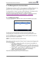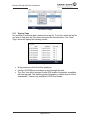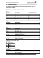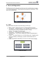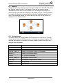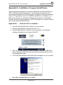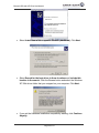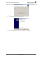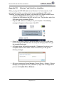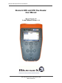
1
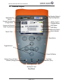
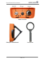
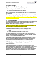
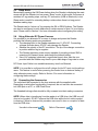
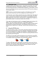
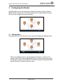
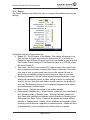
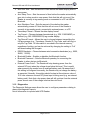
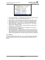
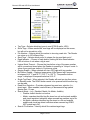
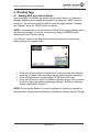
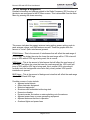
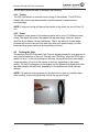
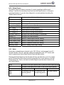
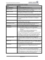
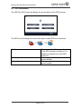
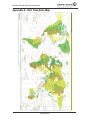
Biomark HPR and HPR Plus User Manual Biomark HPR and HPR Plus Reader User Manual Manual Version 02 To Suit Software Version: 1.10 705 S. 8th Street, Boise, Idaho 83702, USA www.biomark.com Biomark HPR and HPR Plus User Manual Regularity Notices and Conformity USA – FCC Information to the user (FCC Part 15.105) This equipment has been tested and found to comply with the limits for a Class B digital device, pursuant to Part 15 of the FCC Rules. These limits are designed to provide reasonable protection against harmful interference in a residential installation. This equipment generates, uses, and can radiate radio frequency energy and, if not installed and used in accordance with the instructions, may cause harmful interference to radio communications. However, there is no guarantee that interference will not occur in a particular installation. If this equipment does cause harmful interference to radio or television reception, which can be determined by turning the equipment off and on, the user is encourage trying to correct the interference by one or more of the following measures: Reorient or relocate the receiving antenna Increase the separation between the equipment and receiver Connect the equipment to an outlet on a circuit different from that to which the receiver is connected Consult the dealer or an experienced radio/TV technician for help Modification warning (FCC Part 15.21) Warning: Any changes or modifications not expressively approved by Aleis could void the user's authority to operate this equipment. The following antennas are approved to be used with this device: Biomark Handheld 7" Loop Antenna, Model number HPR-ANT Canada This Class B digital apparatus complies with Canadian ICES-003. Cet appareil numérique de la classe B est conforme à la norme NMB-003 du Canada. Biomark HPR and HPR Plus User Manual Table of Contents 1 2 3 Reader Overview _____________________________________________________ 5 1.1 Product Description ____________________________________________________ 5 1.2 Illustrated Diagram ____________________________________________________ 6 1.3 Supplied Equipment ____________________________________________________ 8 1.4 Care and Maintenance __________________________________________________ 8 1.5 Updating Software _____________________________________________________ 9 Getting Started ______________________________________________________ 10 2.1 Switching the Reader On and Off ________________________________________ 10 2.2 Charging the Reader __________________________________________________ 10 2.3 Sleep Mode __________________________________________________________ 11 2.4 Using Alternate DC Power Sources_______________________________________ 11 2.5 Connecting the Accessories _____________________________________________ 11 2.6 Setting the Clock ______________________________________________________ 12 2.7 Using the GPS Receiver ________________________________________________ 12 Configuring the Reader _______________________________________________ 13 3.1 3.1.1 3.1.2 3.1.3 3.2 4 Profiles ______________________________________________________________ 19 Reading Tags _______________________________________________________ 20 4.1 Reading RFID tags with the Reader ______________________________________ 20 4.2 RF Settings & Diagnostics ______________________________________________ 21 Tuning ___________________________________________________________________ 21 Power ____________________________________________________________________ 21 4.2.1 4.2.2 5 Settings Menu ________________________________________________________ 13 Device ___________________________________________________________________ 14 Diagnostics _______________________________________________________________ 15 Memory __________________________________________________________________ 16 4.3 Testing the Unit _______________________________________________________ 22 4.4 Test Mode ___________________________________________________________ 23 File Management & Communication ____________________________________ 24 5.1 5.1.1 5.2 5.2.1 5.2.2 5.2.3 File Management Menu ________________________________________________ 24 Viewing Tags______________________________________________________________ 25 Connecting the Reader to other devices via USB or Bluetooth ________________ 26 Connecting a PC to the Reader Using USB _______________________________________ 26 Connecting to the Reader Using Bluetooth _______________________________________ 26 Connecting a USB Memory Stick ______________________________________________ 26 5.3 Command Interface ___________________________________________________ 28 5.4 File Formats _________________________________________________________ 30 Page 3 of 47 Biomark HPR and HPR Plus User Manual 5.4.1 5.4.2 6 Tag File Format ____________________________________________________________ 30 Log File Format ____________________________________________________________ 30 Tools and Diagnostics ________________________________________________ 32 6.1 Power _______________________________________________________________ 32 6.2 Reports ______________________________________________________________ 33 Startup Report _____________________________________________________________ 33 Status Report ______________________________________________________________ 34 Noise ____________________________________________________________________ 34 Alarms ___________________________________________________________________ 35 6.2.1 6.2.2 6.2.3 6.2.4 6.3 GPS Information ______________________________________________________ 37 Appendix A - UTC Time Zone Map _________________________________________ 38 Appendix B - Installation of Legacy Serial Drivers _____________________________ 39 Appendix B.1. Windows XP Driver Installation ________________________________ 39 Appendix B.2. Windows 7 and Vista Driver Installation _________________________ 42 Appendix B.3. Test Serial Connection in BioTerm ______________________________ 45 Appendix C – List of Settings and Default Values ______________________________ 47 Page 4 of 47 Biomark HPR and HPR Plus User Manual Reader Overview 1.1 Product Description The HPR Plus and HPR readers (Reader) are handheld 134.2 kHz radio frequency identification (RFID) tag readers intended for use with animal tags. The Reader has been designed specifically for use in fish and wildlife research applications. Consequently, it is the most capable and versatile reader available today for this purpose. The HPR Reader is well suited to handheld field use, and bench top use. The HPR Plus Reader contains additional features to facilitate standalone remote monitoring applications. The Reader features: - Rugged drop-proof and waterproof housing - Memory for storage of over 1 million tag reads - High-performance ISO 11784/11785 HDX/FDX-B 134.2 kHz RFID reader with continuous automatic antenna tuning with the HPR Plus - Internal high-capacity lithium battery pack - 4.3” High resolution color TFT LCD display - 454MHz ARM9 core CPU - Class 2 Bluetooth interface - GPS synchronized clock - "Geotagging" of RFID tag reads with the HPR Plus - USB 2.0 On-The-Go (OTG) interface for PC or memory stick connection - Dual purpose hand strap and belt loop - Sophisticated data logging and diagnostic features - Detachable wand antenna - Wide range DC power input for use in remote monitoring applications and easier field recharging - Simple upgrading of Reader software via a USB memory stick - Remote control of the Reader via Bluetooth, USB, or USB RS232 adapter Page 5 of 47 Biomark HPR and HPR Plus User Manual 1.2 Illustrated Diagram Tag Reading Status & Tag Reading Mode Light Sensor & Serial # Current File & Number of Tags Within Battery Level & Charging Status Current and Previous Read Tag Numbers GPS Signal USB Status Bluetooth Status Alarm Indicator Date & Time Read Button Toggle Buttons Power/OK Button Battery Charge & Alarm Indicator (orange) Tag Read Indicator (blue) Waterproof Vent Front Panel Page 6 of 47 Biomark HPR and HPR Plus User Manual DC Input USB OTG Antenna Reader Connectors Folding Desk Stand Attached Loop Antenna Page 7 of 47 Biomark HPR and HPR Plus User Manual 1.3 Supplied Equipment 1. Biomark HPR Unit, (the Reader) 2. Biomark HPR Loop Antenna 3. Fish-Shaped FDX-B RFID Key-chain Test Tag 4. Power Charger Kit (100-240V input, 24V 30W output) 5. 2 m Antenna Cable 6. 2 m USB Cable for PC Connection 7. 0.5 m USB Cable for Flash Drive connection 8. Desk Stand 9. Combined Adjustable Hand Strap & Belt-Loop 10. User Manual (on Biomark flash drive provided) 11. Custom soft case Please ensure you have received all of the above equipment upon receipt of your new Reader. Optional Accessory Equipment 1. 2. 3. 4. DC Power Input Cable HPR to LEGACY Antenna Cable Adapter Hard-shell Protective carry case Hard-shell Protective remote monitoring case/enclosure 1.4 Care and Maintenance While the HPR Reader has been designed to be as rugged and durable as possible, please observe the following points to ensure your Reader provides many years of trouble free service: Charge the battery before first using the Reader or before putting the Reader into storage. The protective caps should be fitted to the connectors whenever possible to protect them from corrosion, dust, and physical damage. Always properly tighten the locking collets on cables connected to the Reader to prevent moisture entering the connectors and damaging the contacts. If the Reader has become wet, ensure the connectors and their caps are dry before removing the cables and replacing the caps. This is to avoid “locking in” the moisture and causing corrosion damage to the contacts. If the Reader is exposed to salt water, rinse the entire unit with fresh water and dry it before removing the cables. Clean and dry the reader before putting it back into its carry case. NOTE: Water cannot enter into the Reader through the connectors with or without the protective caps fitted, but the moisture could damage the terminals in the connectors. Page 8 of 47 Biomark HPR and HPR Plus User Manual 1.5 Updating Software Updates may become available that either enhance the HPR Readers ability function or to fix a known error. To successfully update the reader, please observe the following steps: Download the latest software from the below link. It will read “HPR-X.XXrcX”, where X is the version number. http://www.biomark.com/technical_services/firmware___applications/. Unzip the file and place the folder ‘HPR’ on to a Flash Drive. Power the Reader up and allow it to boot to the main screen. Plug the 0.5 m USB Cable for Flash Drive connection into the Reader. Plug the Flash Drive into the cable end. The Reader will automatically detect the new software on the Flash Drive and will ask for if you would like to update. NOTE: If multiple versions of software are loaded on the Flash Drive, you will have to scroll to the version you wish to load using the up and down arrows. Select ‘Yes’ and the Reader will begin to update its software. It is normal for the Reader to reboot during this process. Once the Reader has returned to the main screen the update is complete. Page 9 of 47 Biomark HPR and HPR Plus User Manual 2 Getting Started 2.1 Switching the Reader On and Off The unit can be powered on by any of the following methods: 1. Connecting the unit to the AC Adapter 2. Holding the OK button for more than 1 second. NOTE: Once the unit has been powered up, it will take up to 30 seconds to boot into the software. The unit can be powered off by holding the OK button for more than 1 second. A menu will pop up asking the user to confirm the shutdown. In the event of a software crash, the unit can be forced off by holding the OK button down for longer than 10 seconds. 2.2 Charging the Reader The Reader has an internal 28.8W/h lithium iron phosphate (LiFePO4) battery. This type of lithium battery is much safer and has a longer cycle life than lithium batteries typically used in consumer electronics. To preserve the life of the battery, the Reader should be fully charged before first use and also before the Reader is put away into storage. To charge the Reader’s internal lithium battery, follow these steps: 1. Plug the DC Jack on the charger into the center plug on the end of the Reader. 2. Connect the charger to a grounded AC power socket. The battery charge indicator will continuously light orange while the battery is charging, and change to green once the battery is charged. The Reader will take around 4-5 hours to charge a completely flat battery. If the charger is connected and the charge indicator is neither green nor orange then the Reader is not charging. Check the connections and verify that the DC input voltage cutout setting discussed in section 3 is configured correctly. NOTE: The battery cannot charge if the internal temperature of the Reader is below 0°C (32°F) or above 60°C (140°F). The unit will indicate a charging error under these conditions. Please be aware that when using the reader in environments below freezing temperature, the battery's ability to supply current will be reduced. This will reduce the Reader's battery run-time and possibly reduce the maximum usable RF transmit power setting. Please use the lowest practical RF power setting (refer to section 4.2.2) under these conditions to avoid excessively loading the battery. Page 10 of 47 Biomark HPR and HPR Plus User Manual 2.3 Sleep Mode Momentarily pressing the OK/Power button when the Reader is displaying the main screen will put the Reader into low power “Sleep” mode. In this mode, the screen is switched off, tag reading stops, and any PC connection (USB or Bluetooth) is lost. Sleep mode is useful for extending battery runtime when there is a long period between reading tags. The Reader can be “woken up” by pressing the OK or READ buttons. The Reader can also be configured to auto-sleep after a certain amount of time if it is not being used. Please refer to Section 3 for more information about configuring this setting. 2.4 Using Alternate DC Power Sources It is possible to use alternate DC sources to charge and power the Reader provided the following points are considered: The charging input to the Reader operates over 11-30V DC. Connecting voltages sources above 30V DC may damage the Reader. Observe the polarity of the DC connection. The tip of the charger connection is positive and the ring is negative. The Reader requires a power source capable of providing at least 20W to operate at full transmit power and charge the internal battery. Use of AC adapters (particularly ungrounded types) other than the one provided with the Reader may result in poor read range of tags due to noise. DC Power Input Cable is an available accessory item from Biomark. NOTE: It is possible to configure the cut-off voltage for the DC input via the settings menu. This feature is useful when powering the reader from an external battery or other alternate power supply. Refer to Section 3 for more information on configuring these settings. 2.5 Connecting the Accessories The unit should be connected to the loop antenna with the supplied cable. Depending on what other functionality is required, the unit can also be connected to a USB port on a PC, or USB Flash Drive. The threaded locking collets should be fully screwed onto their mating connectors. NOTE: When data is transferring from the reader to a USB drive, the USB icon will show a lock symbol. DO NOT remove the USB drive while the lock status symbol is showing. Failure to observe this procedure can result in loss or corruption of data from the USB drive. Un-safe to disconnect: Safe to Disconnect: Page 11 of 47 Biomark HPR and HPR Plus User Manual 2.6 Setting the Clock To keep the clock in the Reader accurate, it will update automatically via the GPS satellite network whenever a GPS signal is available. The precise clock is useful for synchronizing tag reads in multiple Reader installations. In this situation, ensure that all of the Readers have been synchronized with the GPS time when setting up a multi-reader system. NOTE: So that your local time appears correctly on the display and in log files, please set the current time zone in the settings menu (refer to Section 3). To set the clock, move outside or place the unit near a window with a clear view of the sky. The time taken to update the clock will depend on the quality of the GPS signal, varying from a few seconds to a few minutes. You will notice the time and date change to the correct values. If the clock has not updated after 5 minutes, try positioning the reader in an area with a better view of the sky. If the reader clock has become invalid, a message will appear upon turning on the reader: “The Clock Could Not Synchronize – GPS Signal Is Required.” This can happen if the Reader has been in storage for a long time and the internal battery has become deeply discharged. Fully recharge the battery as soon as possible before using the unit to read tags. Follow the above procedure to set the clock. 2.7 Using the GPS Receiver The HPR Plus Reader is able to store location information (latitude and longitude) along with each tag read, this is known as “geotaging.” Geotagging can be turned on or off in the settings menu, please refer to Section 3. When using this feature, be sure that the unit has a valid GPS lock; otherwise the geotag information will not be stored along with the tag read. The GPS icon on the main screen will change from red to blue when a valid GPS lock is obtained and the Reader is now tracking its location. One arc indicates a fix on 4 satellites and two arcs indicates a fix on more than 4 satellites. To obtain a GPS lock, position the Reader in an area with a clear view of the sky. Achieving a valid GPS lock usually takes less than 2 minutes, but can take up to 5 minutes or more, particularly if the Reader has not been operated in the area before or has been switched off for a long time. Page 12 of 47 Biomark HPR and HPR Plus User Manual 3 Configuring the Reader The Main Menu can be accessed by pressing the left hand “soft-key” labeled MENU on the home screen. From here, pressing the corresponding arrow keys allows for fast navigation through the menus. Main Menu Screen 3.1 Settings Menu Pressing the UP key from the main menu screen will display the Settings menu. Settings Menu When in the Settings menu, use the toggle arrow buttons to select a subsetting. Press OK to edit the highlighted setting. Use the arrows keys to alter the selection, and then press Save to confirm the change. Pressing the Back button will return to return to previous menu. Page 13 of 47 Biomark HPR and HPR Plus User Manual 3.1.1 Device The Device Settings menu allows the user to configure the hardware and set local settings. Device Settings Parameters that can be customized are: Reader ID – The ID number of the Reader. This number will appear in log files, tag files, and when connecting the Reader to a PC. It is useful for Readers to have different IDs when more than one Reader is used at a time. The Reader ID also forms part of the Bluetooth name, e.g. HPR-XX, where XX is the Reader ID. Time zone – Set this to your current UTC offset to ensure the correct local time is displayed and stored in tag/log files. Refer to Appendix A for a time zone map or look up your current time zone on the internet. Be sure to account for any daylight saving hours that may be in effect in your area. Backlight Brightness – Set the desired screen backlight brightness. Lower settings will save battery power; a higher setting is useful for viewing the device in full sun. Note that under dark or shady conditions the display will auto-dim. The Reader will return to the configured brightness level when it encounters bright conditions again. Beep Volume – Adjusts the volume of the audible indicator. Power-save in Standby only – When selected, reader will only Auto Sleep or Auto Shutdown when in Standby mode. When de-selected, readers will Auto Sleep after identified time elapses while in Standby or Reading mode. Setting the Auto Sleep Time to ‘0 minutes’ will disable the feature while in Standby or Reading mode. Reader will not shutdown automatically unless external power is removed; regardless of operating mode. Reader will bootup automatically, in last operating mode, when power is re-applied. Page 14 of 47 Biomark HPR and HPR Plus User Manual Auto Dim Time - Sets the amount of time before the reader display dims to save power. Auto Sleep Time – Sets the amount of time before the reader automatically goes into to sleep mode to save power. Note that this will not occur if the Reader is currently in tag reading mode or connected to a PC via USB or Bluetooth. Auto Shutdown Time – Sets the amount of time before the reader automatically powers off. Note that this will not occur if the Reader is currently in tag reading mode, connected to external power, or a PC. Timestamp Format – Selects the date display format. Tag Format – Chooses between hexadecimal (e.g. 3D9.1748D3AD9F) or decimal (e.g. 985.100006080033) tag number display. Tag Record Format – Allows the user to choose between transmitting the full tag message (e.g., Timestamp, Reader ID, Tag Code, and Lat/Long) or only the Tag Code. All information is recorded in the internal memory, regardless of setting, and can be retrieved by changing the setting to ‘Full’ and downloading the file again. RS232 Baudrate – Choose between serial connection baudrates (e.g., 9600, 38400, 115200). Bluetooth Enable – Enables or disables the Bluetooth function. Bluetooth Password – Sets the Bluetooth passkey for connecting the Reader to other devices via Bluetooth. External Power Cutoff - The Reader will stop drawing power from the external DC input when the voltage drops below this level. This is useful when powering the reader from an external battery pack. Be aware that if this setting is configured incorrectly, the Reader may not charge the battery as expected. Normally, this setting should be kept at the minimum value of 10.5 volts unless an unusual DC power input is being used (e.g. an external battery pack). Note that a low power draw will still continue from the external power source even if the voltage is below the cutoff level. 3.1.2 Diagnostics The Diagnostic Settings menu allows the user to configure parameters relating to alarms and diagnostic reports. Not all information is reported with HPR Reader. Page 15 of 47 Biomark HPR and HPR Plus User Manual Diagnostics Settings Send Communications – send diagnostic messages to the selected device (e.g. battery low, memory full, low antenna current, etc.). Alarm Indicator – Choose to beep and/or flash the orange LED indicator. Status Report Interval –How often to run and store a new Status report. Noise Report Interval – How often to run and store a new Noise report. Backg. Noise High – Triggers an alarm message when RF background noise is above the selected level. Memory Low – Triggers an alarm message when Memory capacity has dropped below the selected level. Antenna Current Low – Triggers an alarm message when the antenna current falls below the selected level. External Power Alarm – Triggers an alarm message when external power input voltage falls below the selected level. Does not cut off power being drawn from the DC power input, this function is achieved by the “External Power Cutoff” parameter in the “Device” settings (see previous subsection). 3.1.3 Memory The Memory Settings menu allows the user to configure parameters associated with tag reading and data storage. Not all parameters are available with HPR Reader. Page 16 of 47 Biomark HPR and HPR Plus User Manual Memory Settings Tag Type – Selects which tag types to read (FDX-B and/or HDX) Store Tags – When unselected, read tags will be displayed on the screen, but will not be stored into a file. File Number – Selects which file number to store tag reads into. The Reader can store up to 100 different files. Send Tags – Selects which port(s) to stream live tag read data out of. Read Indicator – Choose to beep and/or flashing the blue Read Indicator LED at bottom of unit when a tag is read. Unique Mode Timeout – Choose the time before a tag of the same number will be re-read and stored when the Reader is operating in “Unique” mode. A value of zero performs similar to Continuous mode. Geotag Enable – When selected will store GPS data with tag number. BioThermo Enable – Displays temperature of BioThermo tag if temperature is between 24.2 oC and 50 oC (75.6 oF to 122 oF). “Temperature below range” is displayed if temperature below 24.2 oC. Single Tag Read – When selected, the Reader will read one tag then return to Standby mode. The READ button needs to be pressed before another tag can be read. Read Error Rejection – Provides enhanced tag read error rejection (i.e., ghost tags). When enabled, read efficiency is decreased at tag speeds greater than 1.5 mps. Search Mode – (e.g., Disabled, Match, No Match, Audible). o Disable: search function not active. o Match: searches identified tag file stored on unit and extends audible and visual tag detect indicators when scanned tag matches tag in file. o No Match: searches identified tag file stored on unit and extends audible and visual tag detect indicators when scanned tag DOES NOT match tag in file. Search File Number – Identify which file contains target tags. Page 17 of 47 Biomark HPR and HPR Plus User Manual Search Indicator – Choose to beep and/or flash the blue Read Indicator LED at bottom of unit when a tag satisfies search criteria. Send Search Results – Selects which port(s) to stream search results out of. NOTE: Once a tag file contains more than 20,000 tags, a "Tag File Full" alarm will occur. Tags will continue to be recorded in this file, however only 20,000 tags can be displayed on the Reader screen. Page 18 of 47 Biomark HPR and HPR Plus User Manual 3.2 Profiles The Reader settings can be saved into “profiles” for loading at a later time. Keeping several settings “profiles” stored on the reader allows speedy reconfiguration of the settings for different applications. Profiles Menu Save This function saves the current settings into memory. A window will appear asking for which “Profile Number” to save to. The data in the profile will be overwritten if it already exists. The Reader will ask for confirmation if this occurs. Load This function will load specific settings from memory. A message will appear asking for the “Profile Number” to load. Load Factory Defaults This will reset the settings back the way they were when the Reader was first delivered from the factory. A confirmation window will appear asking to verify this action. When “Yes” is pressed, the Reader will automatically reset all of the settings. Tag data will not be erased. Page 19 of 47 Biomark HPR and HPR Plus User Manual 4 Reading Tags 4.1 Reading RFID tags with the Reader Upon starting up, the Reader will resume the last state it was in, i.e. Reading or Standby. Reading can be started and stopped by pushing the "READ" button on the device. The text at the top of the Main Screen will toggle between "Reading" and "Standby" when the “READ” button is pressed. NOTE: If external power is not connected to the unit, a fully charged battery will run flat after approximately 3-10 hours of continuously being in READING mode depending on the RF power setting. The “Shortcut” button on the Main Screen allows quick access to tag reading related settings via a popup menu. Shortcut Popup Press the Up/Down arrows to toggle from Continuous (constantly read the same tag) to Unique (will read a particular tag again after the preset time). Press the Right arrow to toggle reading FDX-B and/or HDX tags. Press the Left arrow to jump to the Memory Settings screen; this is a useful shortcut to adjust tag reading and storage settings. The Memory Settings screen is described in Section 3. NOTE: Ensure that the Reader is correctly configured to operate as required for the application, paying particular attention to the Memory Settings and RF Settings. Page 20 of 47 Biomark HPR and HPR Plus User Manual 4.2 RF Settings & Diagnostics Detailed information and settings related to the Radio Frequency (RF) functions of the device are configured in the RF Menu screen. This is accessible from the Main Menu by pressing the down arrow key. RF Settings This screen indicates the present antenna tuning setting, power setting, peak-topeak antenna voltage, and RMS antenna current. Three bar graphs show the amount of "noise" (radio interference) present. FDX-B Noise – This is the amount of interference that will affect the read range of FDX-B tags. The higher the noise the lower the read range will be. FDX noise will jump to 99% while a FDX tag is being read, this is normal. HDX Noise – This is the amount of interference that will affect the read range of HDX tags. The higher the noise the lower the read range will be. HDX noise will jump to 99% while a HDX tag is being read, this is normal. HDX noise should normally track the background noise value fairly closely unless HDX specific interference is present. BKG Noise – This is the amount of background noise that will affect the read range of both FDX-B and HDX tags. Possible sources of noise include: Adjacent metal objects Other electronic equipment Motorized equipment Structures with embedded reinforcing steel Excessive vibration Excessive water fluctuation or water splashing onto the antenna Adjacent power lines or power generating equipment Adjacent antennas that are in operation Overhead lights and power lines Page 21 of 47 Biomark HPR and HPR Plus User Manual The RF Menu allows the user to configure the following: 4.2.1 Tuning The HPR Plus allows for manual or auto tuning of the antenna. The HPR Plus Reader will continuously automatically tune the antenna for peak antenna current/voltage. NOTE: Using auto tuning will reduce the number of tag reads per second from 10 to 8. 4.2.2 Power The transmit output power to the antenna can be set to one of 15 different power levels. The higher the power, the greater the tag read range. However, keep in mind this is not always a linear relationship. That is, the amount of read range increase will become less and less with each step up in power setting. Use the lowest practical power setting to prolong battery run time. 4.3 Testing the Unit The supplied Fish RFID Keychain Test Tag can be placed near the loop antenna to verify correct operation of the unit. This tag is an FDX-B tag. When the RFID tag is placed on-axis, i.e. the fish pointing into the loop, the tag should have read range of approximately 10 cm from the centre of the loop, depending on the power setting. The tag ID will appear on the display and the Reader may beep and/or the tag read indicator will flash blue, depending on the audible and visual indicator settings. NOTE: The antenna and tag should not be placed on or near any metallic object while reading, as this will significantly reduce the tag read range. The Antenna and FDX-B Test Tag Page 22 of 47 Biomark HPR and HPR Plus User Manual 4.4 Test Mode The "Test Mode" button will count the number of successful tag reads out of 100 tag reading cycles when a tag is present in the field. This is useful for testing the performance of an antenna setup. Page 23 of 47 Biomark HPR and HPR Plus User Manual 5 File Management & Communication The Reader can interface to a PC or other equipment via USB and Bluetooth. It is possible to view, copy, and delete tag and log files from the Reader itself. It is also possible to “stream” live data via USB or Bluetooth. The Reader can be controlled remotely by commands received via USB or Bluetooth. *Biomark’s Terminal Application ‘BioTerm’ is available on the Biomark website: http://www.biomark.com/technical_services/firmware___applications/ 5.1 File Management Menu To access these features, select the “Files” menu from the Main menu screen. Files Menu The Files menu will list all the files currently stored on the reader, their corresponding size, and the date of the most recent tag read stored in the file. Use the UP/DOWN arrows to highlight the file you wish to perform an action on, then use the OK button to select the file. NOTE: You can select more than one file at a time. After selecting the file(s), press the “Actions” button. A pop-up box will appear with the following options: View Tags – displays the tag file on the screen (only available if a single tag file is selected) Send to PC – transfer the file(s) to the PC via USB or Bluetooth (only available if the PC is running a terminal application such as BioTerm) Copy to USB – copies the file(s) to a USB memory stick (only available if a memory stick is connected to the Reader) Delete – Deletes the file(s) selected Press the corresponding arrow key for the desired action. Page 24 of 47 Biomark HPR and HPR Plus User Manual File Actions Popup 5.1.1 Viewing Tags It is possible to review the data contained in a tag file. To do this, select the tag file you wish to view from the Files menu and press the Actions button. The “View Tags” action will display the following screen: View Tags Screen All tag numbers in this file will be displayed. Use the UP/DOWN arrow buttons to scroll through the data. The “Geo” box will be checked if valid GPS location information is available with this tag read. The detailed geotag information is visible when the file is downloaded. Feature only available in HPR Plus Reader. Page 25 of 47 Biomark HPR and HPR Plus User Manual 5.2 Connecting the Reader to other devices via USB or Bluetooth 5.2.1 Connecting a PC to the Reader Using USB 1. Plug the Reader into a computer via USB port. A dialog will appear on the Reader for 10 seconds when the USB connection is detected. This allows the operator to choose a mode: USB serial mode (legacy) or Native USB (HID) mode. USB serial mode is automatically selected after 10 seconds if the user takes no action. Legacy mode is useful when using the Reader with software that only supports COM ports. The USB icon on the main screen will go blue once a connection has been made. 2. Run the terminal application on your PC. 3. The “Send to PC” action in the “Actions Popup” (refer Section 5.1) will now be available if this function is supported by the particular PC software in use. Data can also be streamed to the PC. Commands can be sent to and from the Reader (the available commands are listed later in this section). NOTE: Additional information on installation of the driver(s) required for legacy serial port mode are provided in Appendix B. 5.2.2 Connecting to the Reader Using Bluetooth 1. Use whatever Bluetooth software is installed in the PC to pair with the device. It will be named "HPR-XX", where XX is the Reader’s ID. The password is the number set in “Menu/Settings/Device” on the Reader. 2. Ensure that the Bluetooth software has assigned a COM port to the device and note the number. If the Reader is successfully connected to a Bluetooth device, the Bluetooth icon on the main screen will go blue. 3. Run the terminal application on your PC. 4. Select the appropriate COM port from the listed ports under the "Bluetooth" heading. 5. The “Send to PC” action in the “Actions Popup” (refer Section 5.1) will now be available if this function is supported by the particular PC software in use. Data can also be streamed to the PC. Commands can be sent to and from the Reader (the available commands are listed later in this section). 5.2.3 Connecting a USB Memory Stick The Reader can be connected to a USB memory stick using the supplied adapter cable. If a USB memory stick has been detected by the reader the USB icon on the main screen will go blue. The “Copy to USB” action will become available in the file actions popup. Live data can also be streamed to the USB stick. When files are copied to the USB stick, they will be placed into a folder called "HPR." Page 26 of 47 Biomark HPR and HPR Plus User Manual NOTE: When data is transferring between the reader and a USB drive, the USB icon will show a lock symbol. DO NOT remove the USB drive while the lock status symbol is showing. Failure to observe this procedure can result in loss or corruption of data from the USB drive. Un-safe to disconnect: Safe to Disconnect: Page 27 of 47 Biomark HPR and HPR Plus User Manual 5.3 Command Interface It is possible to communicate with the reader remotely via Bluetooth, USB, or a USB-to-RS232 converter. The following is a list of the available commands: General Command Description Example Response RFV Report Firmware Version '1.01' RHV Report Hardware Version ‘1.1’ RID Report Reader ID '01' RUT Report Unit Type 'HPR-Plus', 'HPR-Std' Help Command Description ? List all commands Files Command Description FLA List all files FI 'file' Get info for a file FDA Download all tag files FD 'file' Download a tag or log file FEA Erase all tag files. A list will be shown of the files to be erased, and confirmation is required before the files are erased. FE ‘file’ Delete a tag or log file Reports (HPR Plus Reader only) Report ID's ID Report Type s Start-up a Status b Noise Command Description VR'ID' View the latest report RR'ID' Run a report now Page 28 of 47 Biomark HPR and HPR Plus User Manual Settings Command Description Example SLA List all settings (see Appendix C for list of settings and default values) ST'id' Get current value of a setting set 2 2. Timezone = 0 hours S’id’’value’ Set the value of a setting set 2 -7 2. Timezone = -7 hours Power Command Description Example Response POW Get power information Battery: 68% 3.11 V Charger: 0.0 V RSP Go to sleep (not active while connected to PC or external power) RAR Exit and restart HPR software RBT Power reader off and back on RPD Power off RF Control Command Description RA1 Enable the transmitter RA0 Disable the transmitter Page 29 of 47 Biomark HPR and HPR Plus User Manual 5.4 File Formats 5.4.1 Tag File Format Tag files are named in the following format: [tag]_[READER ID]_[FILE ID].tag Tag file entries are recorded in the following format: [TIMESTAMP] [READER ID] [RECORD TYPE] [*] [TAG NUMBER] [GPS CO-ORDINATES] Examples: Live Recorded (i.e. "streamed" data): 20-07-2012 11:46:28 01 TAG 3DD.003BA20748 20-07-2012 11:46:29 01 TAG 3DD.003BA20045 Extracted from memory (i.e. copied to a USB stick or PC from Reader memory): 26-07-2012 15:50:03 01 TAG *3D6.000AC95916 26-07-2012 15:50:03 01 TAG *3E7.0006054AB5 Field Timestamp Reader ID Record Type Asterisk (*) Tag Number Location Description Example Time that the tag was detected, formatted 26-07-2012 15:50:03 according to “Timestamp Format” setting. The Reader ID setting. 01 Tag reads are always “TAG” TAG An asterisk is included if the tag data has * been downloaded from the Reader memory. Tags which are streamed in real-time will not have an asterisk. The tag number, formatted according to 3D6.000AC95916 “Tag Format” setting. If geotagging is enabled, and a valid 46.563160 N 114.442042 location is known by GPS, the coW ordinates will be added. 5.4.2 Log File Format Log files are named in the following format: [log]_[READER ID]_[FILE ID].txt Log file entries are recorded in the following format: [TIMESTAMP] [READER ID] [RECORD TYPE] [CONTENTS] Example: 06-08-2012 02:12:23 0F MSG Power: 100 Field Timestamp Reader ID Record Type Description Time that the message was recorded, formatted according to “Timestamp Format” setting. The Reader ID setting. MSG/ALM/CNF Page 30 of 47 Example 26-07-2012 15:50:03 01 Biomark HPR and HPR Plus User Manual Contents MSG ALM CNF A simple message An alarm condition A setting change Page 31 of 47 MSG Shutting down ALM Low Antenna Current CNF10.FileNumber:0,1 Biomark HPR and HPR Plus User Manual 6 Tools and Diagnostics The Reader has built in diagnostic tools that can aid in troubleshooting or logging of the operating parameters. These features are accessed by selecting the “Tools” menu from the Main Menu. Tools Menu 6.1 Power This screen shows information about the battery and DC input: Battery symbol – displays the amount of charge remaining in battery. Time Remain. – Estimated battery run time (HH:MM) of the Reader given the present rate of power consumption and state of charge. Voltage – The voltage of the battery pack. Temperature – The temperature inside the Reader (°C) External Power – The DC input voltage will be shown if external power is connected. Current – The current flowing in or out of the battery pack. A negative value indicates the battery is discharging, a positive value indicates that it is charging. Health – will indicate if the battery is too hot or too cold to allow charging. Power Info Screen Page 32 of 47 Biomark HPR and HPR Plus User Manual 6.2 Reports To access the built in diagnostic reporting tools available with the HPR Plus, select the “Reports” menu from the “Tools” menu. There are four types of reports accessible from this menu. When a report is run, the results of the report are shown on the screen and also recorded in the Reader’s log file. It is also possible to configure the Reader to automatically run reports at specified intervals. In the case of the automatic reports, the results are only stored in the log file and not displayed on the Reader screen. Reports Menu 6.2.1 Startup Report The Startup Report is only generated once; when the unit is turned on. It can be viewed at any time from the Reports menu, or through a command interface. The reported values were current when the reader started up and do not reflect any changes made afterwards. Software Version number of the installed software OS Version Version number of the installed operating system Hardware Version number of hardware configuration External Power (V) Voltage of an external charger (if connected) Battery (V) Voltage of the internal battery Memory “OK” or an error message Memory Usage (%) Percentage of memory used Total Tags Total number of tags stored in all files Tuning Tuning setting Power Power setting Page 33 of 47 Biomark HPR and HPR Plus User Manual 6.2.2 Status Report The Status Report provides a summary of current operating conditions and settings. It can be run manually at any time from the Reports menu, or through a command interface. It can also be configured to run automatically by setting the “Status Report Interval”. Software Version number of the installed software Read Mode Value of “Read Mode” setting Tags in File Number of tags in current file Memory Usage (%) Percentage of memory used Temperature (°C) Internal temperature of the Reader Ant. Tuning Current antenna tuning position Ant. Current (A) Latest antenna current measurement Ant. Voltage (V) Latest antenna voltage measurement External Power (V) Voltage of an external charger (if connected) Battery (V) Voltage of the internal battery Status Report (mins) Value of “Status Report Interval” setting Noise Report (mins) Value of “Noise Report Interval” setting Min Ant. Current Value of “Antenna Current Low” setting Max Bkg. Noise Value of “Backg. Noise High” setting 6.2.3 Noise Noise data is sampled every transmit cycle (100-150 ms), and averaged over 0.5 second intervals. The 0.5 s average values are displayed on the “RF” screen, and used to generate the Noise Report which filters that data further. Running the Noise Report for the first time will only use data from one 0.5 s sample period. Subsequent Noise Reports will be generated from noise data since the last Noise Report ran. That is, the end of a Noise Report forms the start of data for the next Noise Report. From The start of the report period (end of previous Noise Report period) To The end of the report period (start of next Noise Report period) Average FDX HDX BKG Max The average over the The maximum over reporting period the reporting period Page 34 of 47 Last The latest reading Biomark HPR and HPR Plus User Manual 6.2.4 Alarms This is an information only screen listing all the alarms that have occurred and if the condition still persists. For transient conditions (e.g. high noise), the number of occurrences over time will be displayed. The presence of an Alarm is indicated by a yellow exclamation on the main screen. If an alarm event occurs, the following will happen: A message indicating the last un-acknowledged alarm event to occur and a “View Alarms” shortcut will appear on the main screen. Pressing this button will acknowledge the alarm and display the “Alarms” screen to list all of the alarms that have occurred. Depending on the selected alarm warning type, the orange light on the Reader will flash rapidly and the Reader will beep until the alarm is acknowledged by pressing the “View Alarms” shortcut. Last Alarm Message Alarm Indicator Alarms Shortcut Alarm Message and Shortcut on Main Screen Page 35 of 47 Biomark HPR and HPR Plus User Manual The following table is a list of possible alarm messages: Alarm Problem High Temperature The internal temperature is over 70 °C. Battery Too Hot Charging has stopped because the battery is too hot, it must cool down below 60 °C before it can charge. Battery Too Cold Charging has stopped because the battery is too cold, it must warm up above 0°C before it can charge. Battery Low The battery voltage is too low for transmitting (<2.85V). The battery must be charged before transmitting will be enabled. Battery Dead The battery is critically low (<2.6V) and must be charged. The unit will shutdown after 10 seconds if no charger is connected. High Noise Background noise has been measured over the set threshold (see setting “Backg. Noise High”). Low Antenna Current Antenna current has been measured lower than the set threshold (see setting “Antenna Current Low”) No Antenna The unit is trying to transmit but no antenna is detected. RF Overload This alarm can be caused by (in order of probability): An RF Power setting that is too high and is causing an overload. A battery that is below freezing temperature. A faulty or deeply discharged battery. The RF Power setting should be reduced to avoid this alarm. The Reader will still attempt to read tags but with reduced performance. It may be necessary to stop READ mode and then start READ mode again to clear this fault condition. Low External Power An external charger is connected, and its voltage has dropped below the set threshold (see setting “External Power Alarm”). Tag File Full The current tag file contains more than 20,000 tags. Tags will continue to be recorded in this file, however only 20,000 tags can be displayed on the Reader screen. Low Memory The total free memory has dropped below the set threshold (see setting “Memory Low”). Tags will continue to be recorded. Memory Full There is no free memory remaining, delete a tag file to free some memory. Tags will not be recorded to permanent memory, however up to an additional 20,000 tags can be held in RAM until memory is made available by deleting files. Tags stored in RAM will be lost if the unit is powered off. Page 36 of 47 Biomark HPR and HPR Plus User Manual 6.3 GPS Information The HPR Plus GPS screen will display the current status of the GPS receiver. GPS Information Screen The GPS icon will change from red to blue when a valid GPS lock is obtained. Satellites Altitude (m) Latitude & Longitude The number of satellites currently seen by the GPS receiver. A minimum of 4 satellites is required for a valid GPS location fix. If there is a valid location fix, this is the current altitude. If there is a valid location fix, this is the current location. Page 37 of 47 Biomark HPR and HPR Plus User Manual Appendix A - UTC Time Zone Map Page 38 of 47 Biomark HPR and HPR Plus User Manual Appendix B - Installation of Legacy Serial Drivers This instruction sheet details how to create a USB-serial connection between an HPR or HPR Plus reader and computer. A serial connection will allow you to communicate between the HPR and computer to download tag files and send tag data to PIT tag programs such as P3, MiniMon and BioTerm. In addition to an HPR and a computer, you will need a Windows XP or Windows 7 HPR Serial Emulator Driver (provided by Biomark), an HPR USB cable, an available USB port and communication software BioTerm. Appendix B.1. Windows XP Driver Installation Unzip the HPR Serial Emulator Drivers on your computer. Connect the USB cable to the HPR and turn it on. Plug the USB cable into a USB port on your computer. The following message will appear on the screen of the HPR: Press ‘OK’ or take no action to allow the reader to boot-up in USB Serial mode. Unplug the USB cable from the computer and plug it back in to get the message back again. The Found New Hardware Wizard dialog box will appear on your computer: Select No, no at this time and click Next. Page 39 of 47 Biomark HPR and HPR Plus User Manual Select Install from a list or specific location (Advanced). Click Next. Select Search for the best driver in these locations and include this location in the search: Click the Browse button and select the Windows XP 32bit driver folder that you unzipped on your computer. Click Next. If you get the Hardware Installation compatibility warning, click Continue Anyway. Page 40 of 47 Biomark HPR and HPR Plus User Manual The Hardware Wizard will load the driver. When the New Hardware Wizard is complete, click Finish. Page 41 of 47 Biomark HPR and HPR Plus User Manual Appendix B.2. Windows 7 and Vista Driver Installation When you plug the HPR USB cable into a Windows 7 or Vista computer, it will automatically install its own driver, which is not compatible with HPR reader. Therefore, you need change the driver to the Biomark HPR Serial Emulator driver. Unzip the HPR Serial Emulator Drivers on your computer. Connect the USB cable to the HPR and turn it on. Plug the other end of the USB cable into an available USB port. Plug the USB cable into a USB port on your computer. The following message will appear on the screen of the HPR: Press ‘OK’ or take no action to allow the reader to boot-up in USB Serial mode. Unplug the USB cable from the computer and plug it back in to get the message back again. A Windows driver will install automatically. Remember, this driver is not compatible with the HPR reader. When it is finished, you will get the following message: Go to your computer’s Device Manager (Control Panel -> System -> Device Manager) and expand the Ports (COM &LPT). Right click on Gadget Serial port and click Update Driver Software… Page 42 of 47 Biomark HPR and HPR Plus User Manual This will open an Update Driver Software wizard. Select Browse my computer for driver software. Select Let me pick from a list of device drivers on my computer. Click Have Disk…and browse to where the Windows 7 HPR Serial Emulator Driver is stored on your computer. Click OK and Next to update the driver Page 43 of 47 Biomark HPR and HPR Plus User Manual Once the driver is updated, you will receive the following message. Click Close and you are done. Page 44 of 47 Biomark HPR and HPR Plus User Manual Appendix B.3. Plug the USB cable into a USB port on your computer. The following message will appear on the screen of the HPR: Press ‘OK’ or take no action to allow the reader to boot-up in USB Serial mode. Unplug the USB cable from the computer and plug it back in to get the message back again. Open BioTerm and select the Serial Emulator port option from the Serial Port option box. Test Serial Connection in BioTerm Click Open, read a tag and the tag code will appear on the screen. Note: you will not have to select a baud rate. Page 45 of 47 Biomark HPR and HPR Plus User Manual Page 46 of 47 Biomark HPR and HPR Plus User Manual Appendix C – List of Settings and Default Values Setting 1 2 3 4 5 6 7 8 9 10 11 12 13 14 15 16 17 18 19 20 21 22 23 24 25 26 27 28 29 30 31 32 33 34 35 36 37 38 39 40 41 42 43 Description Reader ID Timezone Auto Sleep Time Auto Shutdown Time Backlight Brightness Beep Volume Timestamp Format Tag Format Store Tags File Number Search Mode Search File Number Search Indicator Send Search Results Send Tags Read Indicator Bluetooth Enable Bluetooth Password Geotag Enable Single Tag Read Read Mode Unique Mode Timeout Tag Type Tuning HDX Tune Power Max Charger Power 28. USB Power Send Communications Alarm Indicator Status Report Interval Noise Report Interval Backg. Noise High Memory Low Antenna Current Low External Power Alarm External Power Cutoff Echo Commands Read Error Rejection BioThermo Enable RS232 Baudrate Power-save in Standby only Tag Record Format Value A0 0.0 hours 0 minutes 0 hours 50 % 100 % 1 (MDY) 0 (HEX) Yes 0 0 (Disabled) 0 3 (Audible, Visual) 0 15 (USB-PC, USB-Drive, Bluetooth, USB-Serial) 3 (Audible, Visual) Yes 1234 Yes No 1 (Unique) 1 minutes 3 (FDX, HDX) 25 (Manual) 0% 86 % 7 (16 W) 1 (3 W) 15 (USB-PC, USB-Drive, Bluetooth, USB-Serial) 3 (Audible, Visual) 0 minutes 0 minutes 50 % 10 % 0.5 amps 10.5 volts 10.5 volts Yes Yes Yes 9600 Yes Full Page 47 of 47