1
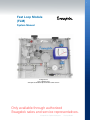
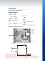
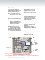
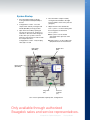
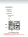
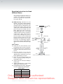
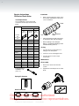
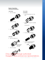
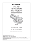
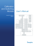
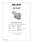
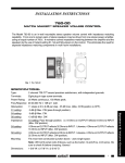
Fast Loop Module User’s Manual AA Swagelok Swagelok®® Pre-Engineered Pre-Engineered Subsystem Subsystem • Pre-engineered subsystems available in weeks, not months. • Field-tested design ensures optimum system performance. Only available through authorized Swagelok sales and service representatives. 2 Contents Fast Loop Module System Manual . . . . . . . . . . . . . . . . . 3 Introduction . . . . . . . . . . . . . . . . . . . . . . . . . . . . 4 Configurations . . . . . . . . . . . . . . . . . . . . . . . . . . . 5 Mounting . . . . . . . . . . . . . . . . . . . . . . . . . . . . . 10 Installation . . . . . . . . . . . . . . . . . . . . . . . . . . . . 12 System Startup . . . . . . . . . . . . . . . . . . . . . . . . . . 13 Operation . . . . . . . . . . . . . . . . . . . . . . . . . . . . . 15 Maintenance . . . . . . . . . . . . . . . . . . . . . . . . . . . . 16 Troubleshooting . . . . . . . . . . . . . . . . . . . . . . . . . . 20 System Component User Instructions . . . . . . . . . . . . . . . 24 Swagelok Instructions Swagelok Tube Fitting Instructions for 1 in. (25 mm) and smaller fittings, MS-12-01 . . . . . . . . . . . . . . . . . 24 Swagelok VCO Fittings Installation Instructions, MS-CRD-VCO . . . . . . . . . . . . . . . . . . . . . . . . . 25 Packing Adjustment for 40 Series Ball Valves, MS-INS-40 . . . . . . . . . . . . . . . . . . . . . . . . . . . 27 Packing Adjustment for 40G Series Ball Valves, MS-INS-40G . . . . . . . . . . . . . . . . . . . . . . . . . . 28 R3A Series Externally Adjustable Relief Valve Maintenance Instructions, MS-CRD-0013 . . . . . . . . . . . 29 R4 Series Relief Valve Maintenance Instructions, MS-CRD-0048 . . . . . . . . . . . . . . . . . . . . . . . . . 36 Plug Valve Subassembly Replacement and O-Ring Rebuild Instructions, MS-CRD-0012 . . . . . . . . . . . . . . 38 Repacking Instructions for N and HN Series Valves, MS-INS-N . . . . . . . . . . . . . . . . . . . . . . . . . . . . 39 CH Series Check Valve Service Instructions, MS-CRD-0025 . . . . . . . . . . . . . . . . . . . . . . . . . 41 Tornado™ Instructions Tornado Model 601 Element Replacement Kit Instructions Element Kit Part #601-5TX . . . . . . . . . . . . . . . . . . 47 Tornado Model 601 Flow Screen Replacement Instructions Flow Screen Kit Part #601-6XX . . . . . . . . . . . . . . . . 49 Tornado Model 602 Maintenance Instructions . . . . . . . . . . 51 Only available through authorized Swagelok sales and service representatives. A Swagelok Pre-Engineered Subsystem Fast Loop Module 3 Fast Loop Module (FLM) System Manual Configuration 4 1/2 in. Liquid System with Optional Grab Sample and Relief Outlets Shown Only available through authorized Swagelok sales and service representatives. A Swagelok Pre-Engineered Subsystem Fast Loop Module 4 Introduction Fast Loop Systems are designed to handle high flows in sample transport lines to reduce time delays for online analyzer systems. Located at the analyzer and offering a bypass, the Swagelok® Fast Loop Module (FLM) can isolate the sample system and introduce a purge gas for system cleaning. The FLM extracts a sample through a filter while using the high flow rate of the fast loop to keep the filter element clean. All FLM subsystems feature dual interlocked ball valves which enable the fast loop to be bypassed when the analyzer is not in service. This feature maintains flow through the fast loop system and improves overall system performance once the analyzer is back online. Only available through authorized Swagelok sales and service representatives. A Swagelok Pre-Engineered Subsystem Fast Loop Module 5 PR PR FP PR FP FP FM Configurations PR FP PR FP FP FP FP FM FP FFL MV FFL BV FM MV BV NV PSV CV PI CV NV FM SHV FC FM SSV SN PSV SHV PI V PV BV RV SSV CV PI PI NV PI FI NV1SN Filter - fast loop PV SSV RV SN SHV SN PV PSV RV PV CV Plug valve SSV SHV NV RV PV RVRelief valve, (optional) NV SSV BV SN PV SSV NV PSV BV SN NV NV PV NV SNSnubber fitting-gauge protector (standard for liquid service) BV PV FI PressureSHV indicator FI NV C NV1 C PSV C FI PV PSV NV1 CV SN SN NVNeedle valve - grab sample or BV CVoutlet purge SHV FI BV MV BV MV BV SN SHV C NV1 FI FI NV SHV FI NVNeedle valve - flow indicator PSV NV NV PI CV PSV FI SHV FFL C FFL NV1 MV BV SSV RV FFL CV PI NV1 FFL FIFlow indicator MV BV FC FM PSV MV C NV FP FI FI FI CVRV FI FP PI NV1 NV FP RV FFL FM C BV PSV FC Ball valve CVCheck valve C FI PI FI FI FI MV PR PR NV1 C C NV1 PI BV MV BV NV1 FP FI FC FM FI FFL FI FC BV FP FFL FC FM Configuration Symbols FM FC FM FFL FP The FLM is FFL available in four main configurations. See the Fast Loop Module Application FM PR Guide, MS-02-361, forFPadditional information. FC FP FM FM FM FP FP FC FM FC FM FM PR FM NV RV Configuration 1: Base Module, Bypass Only NV CV SSV SHV BV PV NV SN Needle valve (NV) RV SSV PV BV Flow indicator (FI) NV BV Ball valve (BV1/BV2) Pressure indicator (PI) Filter (FFL) NV (Liquid) Fast Loop Out Fast Loop In C FI NV (Gas) BV2 C BV1 PI Only available through authorized Swagelok sales and service representatives. SN (Liquid) To Analyzer FFL A Swagelok Pre-Engineered Subsystem Fast Loop Module 6 Configurations Configuration 1: Base Module, Bypass Only with Grab Sample and Relief Outlets Shown Grab sample needle valve (NV2) Flow indicator (FI) Ball valve (BV1/BV2) Relief valve (RV) Needle valve (NV1) Pressure indicator (PI) Filter (FFL) Grab Sample Outlet NV1 NV2 Fast Loop Out (Liquid) FI NV1 C (Gas) BV2 Fast Loop In C BV1 PI SN (Liquid) Relief Outlet To Analyzer FFL RV Only available through authorized Swagelok sales and service representatives. A Swagelok Pre-Engineered Subsystem Fast Loop Module 7 Configurations Configuration 2: Return from Analyzer To Process Grab sample needle valve (NV2) Flow indicator (FI) Ball valve (BV1/BV2) Relief valve (RV) Needle valve (NV1) Pressure indicator (PI) NV1 NV2 Fast Loop Out Filter (FFL) (Liquid) C FI NV1 (Gas) BV2 Fast Loop In CV C From Analyzer BV1 PI SN (Liquid) RV To Analyzer FFL Only available through authorized Swagelok sales and service representatives. A Swagelok Pre-Engineered Subsystem Fast Loop Module 8 Configurations Configuration 3: Return from Analyzer Switch Drain Grab sample needle valve (NV2) Ball valve (BV3/BV4) Flow indicator (FI) Ball valve (BV1/BV2) Relief valve (RV) Needle valve (NV1) Filter (FFL) Pressure indicator (PI) Plug valve (PV) NV1 NV2 (Liquid) FI Fast Loop Out NV1 C (Gas) BV2 CV2 Fast Loop In C BV1 Oily Drain (Vent) PV CV1 From Analyzer C BV3 PI SN (Liquid) FFL RV To Analyzer Oily Drain (Vent) Only available through authorized Swagelok sales and service representatives. A Swagelok Pre-Engineered Subsystem Fast Loop Module 9 Configurations Configuration 4: Gas or Liquid Purge, Manual Drain Grab sample needle valve (NV2) Ball valve (BV3/BV4) Flow indicator (FI) Ball valve (BV1/BV2) Purge needle valve (NV3) Needle valve (NV1) Relief valve (RV) Pressure indicator (PI) Filter (FFL) Plug valve (PV) NV1 NV2 (Liquid) FI NV1 Fast Loop Out (Gas) C BV2 BV4 Oily Drain (Vent) CV2 PV NV3 CV3 Purge Fast Loop In C CV1 BV3 PI SN (Liquid) RV From Analyzer C BV1 FFL To Analyzer Oily Drain (Vent) Only available through authorized Swagelok sales and service representatives. A Swagelok Pre-Engineered Subsystem Fast Loop Module 10 Mounting The FLM must be mounted to a vertical face or wall for function of the flowmeter and to allow for gravity to assist in draining the system. Mount the FLM as close to the analyzer inlet system or analyzer as possible. The FLM is designed to flow with fast loop (process) connections on the left and the outputs to the analyzer on the right. System operation is not recommended in any other orientation. The mounting holes are designed to fit over the bolt heads and assist in mounting. Attach with 1/4 in. fasteners with a maximum head size of 1/2 in. (not provided) in the four mounting holes on the plate. Dimensions, in inches (centimeters), are for reference only and are subject to change. 1/4 in. Fast Loop Module Top 4 mounting holes for 1/4 in./6 mm socket head cap screw or hex head bolt 0.40 (1.02) 0.35 (0.89) 1.50 (3.81) 7.50 (19.0) 13.0 (33.0) 13.5 (34.3) Left Side 1.71 (43.4) Right Side Grab sample outlet (option) Fast loop outlet Return from analyzer 0.69 (1.75) 11.9 (302) Fast loop inlet 9.90 (251) Relief outlet (option) Purge in Out to analyzer 0.92 (23.4) 4.56 (116) 5.24 (133) 7.97 (202) 11.0 (279) 12.8 (325) Drain/vent Drain/vent Only available through authorized Swagelok sales and service representatives. 7.15 (182) Weight 22 to 27 lb (10.0 to 12.2 kg) A Swagelok Pre-Engineered Subsystem Fast Loop Module 11 Mounting 1/2 in. Fast Loop Module Top 0.50 (1.27) 4 mounting holes for 1/4 in./6 mm socket head cap screw or hex head bolt 0.75 (1.90) 2.66 (6.76) 15.0 (38.1) 20.2 (51.3) 26.2 (66.5) Left Side Right Side 1.81 (4.60) Grab sample outlet (option) Fast loop outlet Return from analyzer 1.09 (2.77) 16.2 (41.1) Purge in Drain/vent 13.8 (35.1) Fast loop inlet 0.88 (2.24) 6.70 (17.0) 8.10 (20.6) 9.39 (23.9) 10.7 (27.2) Out to analyzer 18.7 (47.5) Relief outlet (option) Drain/vent Only available through authorized Swagelok sales and service representatives. 5.94 (15.1) Weight 65 to 75 lb (29.5 to 34.0 kg) A Swagelok Pre-Engineered Subsystem Fast Loop Module 12 Installation 1/4 inch and 1/2 inch systems have fractional Swagelok tube fittings or metric Swagelok tube fittings for the system connections. Note:For 1/4 in. systems, all inlet and outlet connections are 1/4 in. or 6 mm with the exception of the sample to analyzer connection, which is 1/8 in. or 3 mm. Note: F or 1/2 in. systems, the fast loop out, fast loop in, relief outlet, oily drain (bottom right), and grab sample outlet connections are 1/2 in. or 12 mm; return from analyzer, purge in, and oily drain (center right) connections are 1/4 in. or 6 mm; sample to analyzer connection is 1/8 in. or 3 mm. Note: A ll internal fittings (non-system connections) are fractional fittings. Install Swagelok tube fitting according to the Swagelok Tube Fitting Instructions for 1 in. (25 mm) and smaller fittings, page 24. Inlet Connections 1. Fast Loop In - connect to the sample transport line to be analyzed. 2. Sample to Analyzer - connect to the remainder of the sample conditioning system prior to the analyzer. 3. Return from Analyzer (option) - connect to the outlet line from the analyzer. There must be sufficient pressure to create flow back into the FLM return. 4. Purge In (option) - connect to a purge line. It will be used to purge the sample side of the system prior to servicing. Configuration 4 - The purge media may be either a liquid or a gas. Outlet Connections 5. Fast Loop Out - connect to the return transport line. This line must be at lower pressure than the process supply line and is typically downstream from the sample point. 6. Relief Outlet (option) - connect to a sample disposal. This line will open if an overpressure event activates the relief valve. 7. Grab Sample Outlet (option) - connect to a grab sample unit to collect samples for analysis. 8. Oily Drain × 2 (Vent) (option) - connect to an oily drain or sample disposal suitable for the system media. Fast loop out Grab sample outlet Return from analyzer Purge in Oily drain (vent) Sample to analyzer Fast loop in Oily drain (vent) Relief outlet Only available through authorized Swagelok sales and service representatives. 1/2 in. Fast Loop Module, Gas System, Configuration 4 A Swagelok Pre-Engineered Subsystem Fast Loop Module 13 System Startup 4. Place the FLM in sample mode by moving the black handle to the right. Pressure will be shown on the pressure gauge (PI). 1. Place the FLM in bypass mode by moving the black handle (BV1/BV2) to the left. 2. Configurations 3 and 4 - Close the sample return valve by moving the red handle (BV3/BV4) to the up position. 5. Adjust the flow to the desired rate. 3. Open flow to the FLM by opening all fast loop in, fast loop out, and process return lines. Since the FLM is in bypass mode, allow your system to run for a minimum of five minutes in order to flush the sample return lines. Configurations 3 and 4 - verify the plug valve (PV) is closed. 1/4 in. systems - use the metering valve that is integral to the flowmeter. 1/2 in. systems ■ Gas systems: use the needle valve (NV1) that is upstream of the flowmeter. ■ Liquid systems: use the needle valve (NV1) downstream of the flowmeter. Red handle (BV3/BV4) Needle valve (NV1) Black handle (BV1/BV2) Plug valve (PV) Pressure indicator (PI) 1/2 in. Fast Loop Module, Liquid System, Configuration 4 Only available through authorized Swagelok sales and service representatives. A Swagelok Pre-Engineered Subsystem Fast Loop Module 14 System Startup 6. Verify that flow is reaching the sample conditioning system downstream of the FLM. 7. Adjust the relief valve set pressure, if desired, according to the appropriate instructions. Note: T he relief valve is pre-set at the factory as specified in the ordering information. 1/4 in. - R3A Series Externally Adjustable Relief Valve Maintenance Instructions, page 29. 1/2 in. - R4 Series Relief Valve Maintenance Instructions, page 36. /2 in. systems with Note: 1 perfluorcarbon FFKM seals will contain R3A series relief valves. Red handle (BV3/BV4) Black handle (BV1/BV2) Relief valve (RV) Needle valve (NV1) Pressure indicator (PI) Plug valve (PV) 1/2 in. Fast Loop Module, Gas System, Configuration 4 Only available through authorized Swagelok sales and service representatives. A Swagelok Pre-Engineered Subsystem Fast Loop Module 15 Operation 1. To place the FLM in sample mode, move the black handle (BV1/BV2) to the right. This will switch the flow to the sample side of the FLM. 5. Configuration 4: To adjust purge flow, turn the handle of the purge needle valve (NV3), clockwise for less flow or counterclockwise for more flow. 2. To place the FLM in bypass mode, move the black handle to the left. This allows all FLM flow to bypass the sample side of the loop. 6. To collect a sample from the grab sample outlet, open the needle valve (NV2) . 3. Configurations 3 and 4: To drain the system while in bypass, open the plug valve (PV). Configuration 3 systems may not drain completely. If more effective draining is required, Configuration 4 would be more appropriate. 4. Configurations 3 and 4: To place the system in drain/purge mode, move the black handle to the left to put the FLM in bypass mode. Then move the red handle to the down position to switch the analyzer return line to drain mode and opens the purge lines. (Purge lines are in Configuration 4 only.) Red handle (BV3/BV4) 7. To return the FLM to sample mode, reverse steps 1 through 3. Failure to periodically inspect and maintain valve packing may result in leakage. Swagelok ball valves are designed to be used in the fully open or fully closed position. Grab sample needle valve (NV2) Black handle (BV1/BV2) Purge needle valve (NV3) Needle valve (NV1) Pressure indicator (P1) Plug valve (PV) Only available through authorized Swagelok sales and service representatives. 1/2 in. Fast Loop Module, Gas System, Configuration 4 A Swagelok Pre-Engineered Subsystem Fast Loop Module 16 Maintenance Warning Before servicing any installed system component you must ■ depressurize the system ■ purge the system (when possible). Follow these steps to depressurize your FLM: Ball Valve Packing Adjustment If a packing adjustment is needed on the 40 series ball valves (BV1/BV2 and BV3/BV4) it is not necessary to shut down or remove the system from service. Upper coupling 1. Place the FLM in bypass mode by moving the black handle (BV1/BV2) to the left. Fig. 1. 2. Configurations 1 and 2 - There is no direct method within the FLM to fully depressurize the system. Use external means to depressurize these configurations. 3. Configurations 3 and 4 - Place the system in drain/purge mode by moving the red handle (BV3/BV4) to the down position. Lower coupling 4. Configurations 3 and 4 - Open the purge valve (PV). Fig. 1 System shown in Bypass mode. Shown without tubing or system connections for clarity. 5. Configurations 4 - After a suggested minimum of five minutes, close the purge line by moving the red handle to the up position. 6. Verify that the FLM is depressurized by checking the pressure on the pressure gauge (PI). Interlock flange Black handle Upper coupling Black handle Lower coupling Fig. 2 System shown in Sample mode. Shown without tubing or system connections for clarity. Interlock flange Only available through authorized Swagelok sales and service representatives. A Swagelok Pre-Engineered Subsystem Fast Loop Module 17 Maintenance To access the valve packing, you must remove the black handle subassembly: 8. Adjust the valve packing according to: 1/4 in. - P acking Adjustment Card for 40G Series Ball Valves, page 28. 2. Configurations 3 and 4: Remove the interlock flange. Fig. 2. acking Adjustment Card for 1/2 in. - P 40 Series Ball Valves, page 27. 3. Remove the black handle shaft by turning it counterclockwise. Fig. 2. 9. Configurations 3 and 4, To adjust the valve packing on the 40G valves: 4. Loosen the two set screws on the upper coupling. Fig. 2. ■Loosen the interlock set screws. Fig. 5. 5. Loosen the set screw on the lower coupling. Fig. 2. ■ Remove the interlock gears. 1. Turn the black handle to the left to place the system in bypass mode. Fig. 1. 6. Slide the couplings toward the center. Fig. 3. Interlock set screws Fig. 5 Fig. 3 7. Lift out the black handle subassembly. Fig. 4. Note: C onfiguration 3, only the lower gear must be removed. ■ A djust the valve packing according to Packing Adjustment Card for 40G Series Ball Valves, page 28. Fig. 6. Access to valve packing Access to valve packing Fig. 4 Fig. 6 Only available through authorized Swagelok sales and service representatives. Reverse steps 1 to 8 to replace the handle subassemblies. A Swagelok Pre-Engineered Subsystem Fast Loop Module 18 Maintenance VCO® Fitting Maintenance When required, maintain the VCO fittings within the system according to VCO Fittings Installation Instructions, page 25. Verify that the O-ring is in place when reassembling the fitting. The locations of the VCO fittings within a Configuration 4 FLM are indicated in the drawing below. he VCO fitting locations may vary Note: T slightly between configurations. Configuration 4 1/2 in. Liquid System with Optional Grab Sample and Relief Outlets Shown Only available through authorized Swagelok sales and service representatives. A Swagelok Pre-Engineered Subsystem Fast Loop Module 19 Maintenance System Component Reference for Replacement Ordering Information Proportional relief valve (1/4 in. FLM - R3A series, 1/2 in. FLM - R4 series) Proportional Relief Valves — R Series, MS-01‑141 Plug valve (1/4 in. FLM - P4T series, 1/2 in. FLM - P6T series) Plug Valves — P4T and P6T Series, MS-01-59 VCO fitting VCO O-Ring Face Seal Fittings, MS-01-28 Needle valve — flow indicator (1/4 in. systems - M1 series) Variable Area Flowmeters — G Series and M Series, MS-02‑346 Needle valve — flow indicator (1/2 in. systems - 12N series) Needle valve — optional grab sample outlet (1/4 in. systems - 3N series, 1/2 in. systems - 12N series) Severe-Service Union Bonnet Needle Valves—N Series and HN Series, MS-01-164 Needle valve — optional purge outlet (3N series) Flow indicator (1/4 in. FLM - M1 series, 1/2 in. FLM - M3 series) Variable Area Flowmeters — G Series and M Series, MS-02‑346 Ball valve (40G or 40 series) One-Piece Instrumentation Ball Valves — 40G Series and 40 Series, MS-02-331 Pressure indicator (PGI series, B model) Pressure Gauges, Industrial and Process— PGI Series, MS-02-170 Check valve (CH series) Check Valves — C, CA, CH, CP, and CPA Series, MS-01-176 Snubber fitting Pressure Gauges, Industrial and Process — PGI Series, MS-02-170 Filter Kit Information Element Size 2 micron Module Size Filter Type 1/4 in. FLM 601 Filter 1/2 in. FLM 602 Filter Kit Type 10 micron 25 micron Ordering Number Gasket / Element Kit 601-5T2 601-5T10 601-5T25 Flow Screen Kit 601-62SS 601-610SS 601-625SS Element Kit 602-5T2-1 602-5T10-1 602-5T25-1 Only available through authorized Swagelok sales and service representatives. 5 Piece Element Kit 602-5T2 602-5T10 A Swagelok Pre-Engineered Subsystem 602-5T25 Fast Loop Module 20 Troubleshooting Symptom Cause Remedy Place the FLM into sample mode by moving the black handle to the right. Pressure indicator (PI) shows no pressure. Pressure indicator (PI) shows low pressure. Pressure indicator (PI) shows high pressure. FLM is in bypass mode. Check that both ball valves are turning when black handle is moved – if not, tighten set screws with valve in correct orientation. Fast loop is shut off. Open all valves in fast loop line external to the FLM. The sample supply line is obstructed. Check that there is pressure in sample supply line. There is an obstruction upstream of the FLM. Check that sample fluid is passing through the probe and isolation valves. There is no process pressure. Check that the process line is pressurized. Configuration 3 and 4, the plug valve (PV) may be open. Close the plug valve (PV). The needle valve (NV1) is fully open. Turn the needle valve handle clockwise to restrict flow and increase pressure. The relief valve (RV) is relieving pressure and flowing to the vent. Check the set pressure on the relief valve and increase if necessary. Pressure indicator (PI) is damaged. Check the pressure indicator (PI) and replace if necessary. There is low process pressure. Check the pressure in the process pipe near the sampling nozzle. If flow rate is acceptable, there may be a partial blockage in probe or sample transport lines to the FLM. Partially close the needle valve (NV1) and check for pressure increase on the pressure indicator (PI) – if pressure increases there may be an upstream flow restriction. There is a flow restriction external to the FLM (ex. process probe or regulator not properly sized for the system). Check the pressure at the probe or regulator outlet – if the system is losing pressure replace with a wider-bore probe or different regulator. During initial startup the flow is too low, the fast-loop supply line may be too narrow or too long. Replace the fast-loop supply and return lines with larger tubing. There is high process pressure. Reduce the pressure in the process pipe near the sampling nozzle. The needle valve (NV1) is restricting flow. Turn the needle valve handle counter clockwise to increase flow and release pressure. Pressure indicator (PI) is damaged. Check the pressure indicator (PI) and replace if necessary. If using a liquid fast-loop pump, the return line or process isolation valve may be blocked. Check that the process isolation valve and all valves in the return line are fully open. Then check for possible blockage. Only available through authorized Swagelok sales and service representatives. A Swagelok Pre-Engineered Subsystem Fast Loop Module 21 Troubleshooting Symptom Cause Remedy The needle valve (NV1) is closed too much. Turn needle valve counter clockwise to increase the flow. Configuration 3 and 4, the plug valve (PV) may be open. Close the plug valve (PV). If zero flow indicated, the flowmeter pointer is not following float position. 1/4 in. FLM, close the metering valve and wait for one minute. Slowly open the metering valve and adjust flow to desired rate. 1/2 in. FLM, close the needle valve and wait for one minute. Slowly open the needle valve and adjust flow to desired rate. Adjust the flow rate with the needle valve (NV1) and observe whether the flowmeter indicates the changes. The flowmeter float is stuck in the tube. Flush the system with solvent to remove oil and solid deposits. Remove the flowmeter and clean the inside of the flow tube. The loop pressure is acceptable but there is little or no flow. Replace the flowmeter. One of the bypass valves is not fully closed. Fast-loop pump (if used) is damaged. Move the black handle to the right and verify the two ball valves (BV1/BV2) are fully closed. Release set screws, reposition handle, and retighten set screws. Check the rotation speed of the fast-loop pump. Check the flow rate from pump – repair or replace pump, as necessary. The fast-loop return line or process return nozzle is partially or fully blocked. Check that all valves in fast loop system external to FLM are fully open. The process return pressure is too high. Find a lower pressure point for return to process. During initial startup the flow is too low, the fast-loop supply line may be too small or too long. Replace the fast-loop supply and return lines with larger tubing. Only available through authorized Swagelok sales and service representatives. A Swagelok Pre-Engineered Subsystem Fast Loop Module 22 Troubleshooting Symptom Cause Remedy The filter element is obstructed. Replace the filter element. If possible, increase the fast-loop flow and check for improvement. Filter element is becoming frequently obstructed (e.g. daily replacement needed). Fast-loop pressure and flow are acceptable, but there is little or no flow to the analyzer. If the analyzed sample returns to the FLM, there may not be enough pressure drop in the FLM to drive the sample flow through the analyzer. If the additional time delay is acceptable, decrease the filtered sample flow (consider reducing analyzer bypass flow). Change the element to one with a larger pore size – if analyzer can accept the additional particle load. Restrict the fast-loop flow to increase sample pressure by turning needle valve (NV1) handle clockwise – being careful not to reduce flow too much. Check that the sample return valve (BV3) is fully open – release set screws, reposition handle, and retighten set screws if necessary Consider changing the method of disposing of the analyzed sample. The check valve (CV1) is not cracking. Pressure at sample return point is too high. Maintain or replace the check valve. If the sample is returned via fast-loop return to process, reduce the return line pressure drop by installing a larger size tube or pipe for sample return line to process. Consider changing the method of disposing of the analyzed sample. There is no flow in the grab sample outlet. There is no purge flow. There is high flow resistance in the sample path to the analyzer external to the FLM. Check all sample conditioning equipment, analyzer flow path, and analyzer vent for a closed valve or obstruction. The needle valve (NV2) is closed. Open the needle valve by turning the handle counter clockwise. Pressure indicator (PI) shows zero or low pressure. See cause and remedy for Pressure indicator (PI) shows no or low pressure. The needle valve (NV3) is closed. Open the needle valve by turning the handle counter clockwise. There is insufficient purge fluid pressure. Check that the purge fluid is supplied to the FLM at a sufficient pressure. Drain valve is not open Configuration 4, open the plug valve (PV). The drain is blocked. Check that there is no closed valve in the drain line external to the FLM. Remove any blockage from the drain. The process sample is leaking into system during purge. The FLM is not fully in bypass. Move the black handle to the left. One of the ball valves (BV1/BV2) is not fully in bypass. Release set screws, reposition handle, and retighten set screws. Ball valves BV1 or BV2 need packing adjusted. Tighten the packing according to Maintenance, page 16. Only available through authorized Swagelok sales and service representatives. A Swagelok Pre-Engineered Subsystem Fast Loop Module 23 Troubleshooting Symptom The relief valve is open. Cause Remedy There is excess process pressure. The set pressure is too low. See cause and remedy for Pressure indicator (PI) shows high pressure. Increase the set pressure if necessary. Replace valve spring with the next higher range. There is backflow into the analyzer. Check valve (CV1) is stuck open. Maintain or replace the check valve. Verify orientation when the check valve is reinstalled. Pressure indicator (PI) pointer is vibrating excessively. Fast loop pressure is pulsating. Consider replacing PI with a liquid-filled gauge The snubber is incorrect for the sample viscosity. Replace the snubber with a more restrictive SUS range. Only available through authorized Swagelok sales and service representatives. A Swagelok Pre-Engineered Subsystem Fast Loop Module 24 Swagelok Tube Fitting Instructions for 1 in. (25 mm) and smaller fittings Fig. 1 Fig. 2 Fig. 3 Installation These instructions apply to both traditional fittings and to fittings with the advanced backferrule geometry. 1.Fully insert the tube into the fitting and against the shoulder; rotate the nut fingertight. Fig. 1. High-Pressure Applications and High Safety-Factor Systems: Further tighten the nut until the tube will not turn by hand or move axially in the fitting. 2.Mark the nut at the 6 o’clock position. Fig. 2. 3.While holding the fitting body steady, tighten the nut one and one-quarter turns to the 9 o’clock position. Fig. 3. Note: For 1/16, 1/8, and 3/16 in.; 2, 3, and 4 mm tube fittings, tighten the nut three‑quarters turn to the 3 o’clock position. Gaugeability On initial installation, the Swagelok gap inspection gauge assures the installer or inspector that a fitting has been sufficiently tightened. Position the Swagelok gap inspection gauge next to the gap between the nut and body. Fig. 4. • If the gauge will not enter the gap, the fitting is sufficiently tightened. • If the gauge will enter the gap, additional tightening is required. Reassembly Instructions — You may disassemble and reassemble Swagelok tube fittings many times. Fig. 4 Warning Always depressurize the system before disassembling a Swagelok tube fitting. 1.Prior to disassembly, mark the tube at the back of the nut; mark a line along the nut and fitting body flats. Fig. 5. Use these marks to ensure you return the nut to the previously pulled-up position. 2.Insert the tube with preswaged ferrules into the fitting body until the front ferrule seats against the fitting body. Fig. 6. 3.While holding the fitting body steady, rotate the nut with a wrench to the previously pulled-up position as indicated by the marks on the tube and the flats; at this point you will feel a significant increase in resistance. Fig. 7. 4.Tighten the nut slightly. Fig. 5 Fig. 6 Caution Do not use the gap inspection gauge with reassembled fittings. Fig. 7 Caution Do not mix or interchange parts with those of other manufacturers. Only available through authorized Swagelok sales and service representatives. For additional information, see the Gaugeable Tube Fittings and Adapter Fittings catalog, MS-01-140. A Swagelok Pre-Engineered Subsystem Fast Loop Module 25 Swagelok® VCO® Fittings Installation Instructions Bodies without weld fittings 1 11 12 1 2 1/16, 1/8, 3/16 in. (2, 3, 4 mm) 4 9 8 7 11 6 5 12 1 2 2 3 10 ≥ 1/4 in. ≥ (6 mm) 2 3 10 4 9 8 7 6 5 3 GTAW 4 5 6 Finger-tight Only available through authorized 7 Swagelok sales and service representatives. 45° A Swagelok Pre-Engineered Subsystem Fast Loop Module 26 Swagelok® VCO® Fittings Installation Instructions Bodies with weld fittings 1 2 GTAW 3 4 5 GTAW 6 7 8 Finger-tight Only available through authorized 9 Swagelok sales and service representatives. 45° A Swagelok Pre-Engineered Subsystem Fast Loop Module 27 40 Series Valve Packing Adjustment IMPORTANT This valve is adjusted for factory testing with nitrogen at 1000 psig (69 bar) or the rated pressure if lower than 1000 psig (69 bar). Packing must be readjusted for service at higher than test pressure. Warning: Packing adjustment may be required during the service life of the valve to prevent leakage. Before servicing any installed valve you must depressurize the system, cycle the valve, and purge the valve. Adjust the packing by turning the packing bolt clockwise in 1/16‑turn increments until leak-tight performance is achieved. Always verify proper operation upon installation. Only available through authorized Swagelok sales and service representatives. A Swagelok Pre-Engineered Subsystem Fast Loop Module 28 40G Series Valve Packing Adjustment IMPORTANT This valve is factory tested with nitrogen at 1000 psig (69 bar), or the rated pressure if lower than 1000 psig (69 bar). Periodic maintenance: Packing adjustments may be required during the service life of the valve to prevent leakage. Adjusting the Packing 1.Adjust the packing by turning the packing bolt clockwise in 1/16-turn increments until leak-tight performance is achieved. 2.Test valve for proper function and operation. Before removing any installed valve from the system, you must • depressurize the system • cycle the valve • purge the valve Only available through authorized Swagelok sales and service representatives. A Swagelok Pre-Engineered Subsystem Fast Loop Module 29 R3A Series Externally Adjustable Relief Valves Maintenance Instructions R3A Series Exploded View Tools Required Tool Size Part 3/4 in. Thin head (3/16 in. max) Lock nut 3/4 in. Cap Crow's foot 3/4 in. Thin head (3/16 in. max) Lock nut Hex bit socket 5/64 in. Handle set screw Plug Cap Label Lock wire hole Lock nut Open-end wrench Spring Spring support Bonnet Bonnet O-ring Quad seal Retainer Stem Torque wrench, capable of: 10 in.·lb (1.1 N·m) Set screw 100 in.·lb (11.3 N·m) Lock nut Pic n/a O-rings Seat retainer Seat O-ring Insert Lock wire hole Body Spring Kit Identification Spring Designator and Color Initial Cap Position (number of turns) Set Pressure Range psig (bar) Spring Kit Basic Ordering Number: 177-R3A-K1- Spring Kit A Blue 50 to 350 (3.4 to 24.1) 9 B Yellow 350 to 750 (24.1 to 51.7) 8.5 C Purple 750 to 1500 (51.7 to 103) 9 D Orange 1500 to 2250 (103 to 155) 6 E Brown 2250 to 3000 (155 to 206) 6 F White 3000 to 4000 (206 to 275) 6 G Red 4000 to 5000 (275 to 344) 6 5000 to 6000 (344 to 413) 6 Lockwire Spring Spring support Label Lead seal Only available through authorized Swagelok sales and service representatives. H Green A Swagelok Pre-Engineered Subsystem Fast Loop Module 30 R3A Series Externally Adjustable Relief Valves Maintenance Instructions Definition of Symbols Discard WARNING Before servicing any installed valve, you must • depressurize system • cycle valve • purge the valve 4. Existing spring Existing spring support WARNING Residual material may be left in the valve and system. CAUTION Do not scratch any sealing surfaces while following these instructions. Valve performance could be affected. Spring Installation Lubricate 5.Make sure all components are clean. 6. 1. New spring New spring support Lock nut Loosen 2 . 7. Existing label Cap Loosen 8. New label 9. 3. Cap Cap Thread to initial position indicated in Spring Kit Identification table. Bonnet Only available through authorized Swagelok sales and service representatives. A Swagelok Pre-Engineered Subsystem Fast Loop Module 31 R3A Series Externally Adjustable Relief Valves Maintenance Instructions Manual Override Conversion 10. Manual Override Kit Red handle Cap Lock nut Tighten against cap 1. Follow steps 1 through 4 in the Spring Installation section. Springs A, B, or C can be reused in step 3. 11.Test for set pressure. 12.To adjust set pressure, relieve system pressure and loosen lock nut. ∙ To increase set pressure, tighten cap as needed. ∙ To decrease set pressure, loosen cap as needed. 13.Repeat steps 10 through 12 as necessary to obtain desired set pressure. 2. Plug 3. Spring 14. Pull rod Lock nut Tighten to 100 in.·lb. (11.3 N·m.) 15. 4. Cap Rest on bonnet Cap Bonnet Lockwire Lead seal Body Only available through authorized Swagelok sales and service representatives. A Swagelok Pre-Engineered Subsystem Fast Loop Module 32 R3A Series Externally Adjustable Relief Valves Maintenance Instructions 5. Handle Thread onto pull rod Pull rod 6. Set screw Tighten to 10 in.·lb (1.1 N·m) 7. Cap Thread to initial position indicated in Spring Kit Identification table. 8. To adjust set pressure, see steps 10 through 13 in the Spring Installation section. Only available through authorized Swagelok sales and service representatives. A Swagelok Pre-Engineered Subsystem Fast Loop Module 33 R3A Series Externally Adjustable Relief Valves Maintenance Instructions Definition of Symbols Seat Replacement Tools Required Tool Discard Size Part 3/4 in. Thin head (3/16 in. max) Lock nut 3/4 in. Cap, Bonnet nut 7/8 in. Body wrench pad Crow's foot 3/4 in. Bonnet nut Hex wrench 5/16 in. Seat retainer Hex bit socket 5/16 in. Open-end wrench Lubricate With system compatible lubricant 1. Remove valve from system. 2. Lock nut Loosen 3. Seat retainer Cap Loosen Torque wrench, capable of: 250 in.·lb (28.2 N·m) Seat retainer 600 in.·lb (67.8 N·m) Bonnet nut Pic n/a O-rings 4. Seal Kit Bonnet O-ring Retainer Seat O-ring Bonnet nut Loosen Quad seal WARNING Before removing any installed valve, you must • depressurize system • cycle valve • purge valve 5. WARNING Residual material may be left in the valve and system. Bonnet Body CAUTION Do not scratch any sealing surfaces while following these instructions. Valve performance could be affected. Only available through authorized Swagelok sales and service representatives. A Swagelok Pre-Engineered Subsystem Fast Loop Module 34 R3A Series Externally Adjustable Relief Valves Maintenance Instructions 6. 11. Seat retainer Insert assembly Bonnet O-ring Stem 7. 12. Quad seal Retainer Seat retainer 8. Tighten to 250 in.·lb (28.2 N·m) 13. Seat retainer Seat O-ring Quad seal Retainer Insert Teeth facing away from quad seal 14. 9. Make sure all components are clean. 10. Seat O-ring Stem Lubricate top of stem Insert Only available through authorized Swagelok sales and service representatives. A Swagelok Pre-Engineered Subsystem Fast Loop Module 35 R3A Series Externally Adjustable Relief Valves Maintenance Instructions R3A Series Cutaway 15. Plug Cap Label Bonnet O-ring Lock nut 16. Bonnet Stem Spring Lock wire hole Spring support Bonnet O-ring Lock wire hole Quad seal Retainer Bonnet Seat retainer Seat O-ring Body Insert Body 17. Swagelok proportional relief valves should never be used as code safety relief valves. Some system applications require relief valves to meet specific safety codes. The system designer and user must determine when such codes apply and whether these relief valves conform to them. Bonnet Tighten to 600 in. ·lb (67.8 N·m) Swagelok proportional relief valves are not "Safety Accessories" as defined in the Pressure Equipment Directive 97/23/EC: 18.To adjust set pressure, see steps 10 through 13 in the Spring Installation section. 19.Install valve in system. Grip valve on wrench pad during installation. Only available through authorized Swagelok sales and service representatives. Wrench pad A Swagelok Pre-Engineered Subsystem Fast Loop Module 36 R4 Series Relief Valve Maintenance Instructions Cap Seal and Stem Replacement Instructions Contents: •1 quad seal •1 O-ring •1 bonded stem Lock Nut Bonnet Quad Seal and O-Ring Replacement 1. Remove valve from system. 2. Loosen cap to relieve spring pressure. 3. Remove bonnet from body. 4. Remove stem and retainer from bonnet. 5. Remove quad seal from bonnet. 6. Make sure all parts are clean before reassembly. 7. Install new quad seal into bonnet. (Lubricate with system compatible lubricant.) 8. Place retainer in bonnet, then insert stem into bonnet through retainer and quad seal. 9. Remove and replace bonnet O-ring. (Lubricate with system compatible lubricant.) 10. Thread bonnet into body and torque to 400 in.·lb. (45 N·m). 11. Adjust desired set pressure as described in steps 7 through 10 in the Spring Installation section on reverse side. 12. Install valve in system. Grip valve on wrench pad during installation. O-Ring Quad Seal Retainer Bonded Stem Body Stem and O-Ring Replacement 1. Remove valve from system. 2. Loosen cap to relieve spring pressure. 3. Remove bonnet from body. 4. Remove stem from bonnet. 5. Make sure all parts are clean before reassembly. 6. Place new stem into bonnet. 7. Remove and replace bonnet O-ring. (Lubricate with system compatible lubricant.) 8. Thread bonnet into body and torque to 400 in.·lb. (45 N·m). 9. Adjust desired set pressure as described in steps 7 through 10 in the Spring Installation section on reverse side. 10. Install valve in system. Grip valve on wrench pad during installation. Spring Kit Identification Spring Kit Ordering Number Color Code Nominal Cracking Pressure psig (bar) Initial Cap Position, number of turns 177-13K-R4-A Blue 50 to 350 (3.4 to 24.1) 12.5 177-13K-R4-B Yellow 350 to 750 (24.1 to 51.7) 13.5 750 to 1500 (51.7 to 103) 13.5 Only available through authorized Swagelok sales and service representatives. 177-13K-R4-C Purple A Swagelok Pre-Engineered Subsystem Fast Loop Module 37 R4 Series Relief Valve Maintenance Instructions Spring Installation Warning: Relieve system pressure before installing spring. Plug 10. Lock wire the cap and body together to maintain relief setting. Manual Override Conversion Warning: Relieve system pressure before installing manual override handle. Cap Spring Handle Label Set Screw Lock Wire Hole Cap Lock Nut Spring Support Bearing Label Bonnet Lock Wire Hole Pull Rod Spring Body 1. Loosen lock nut and remove the cap from bonnet. 2. Remove existing spring if necessary. 3. Make sure all components are clean. 4. Place spring support bearing in valve with bearing side UP. 5. Install proper spring for desired set pressure range. 6. Replace existing label with new label. Check this label against spring identification table for proper set pressure range. 7. Thread cap onto bonnet to initial position indicated in Spring Kit Identification Table. Tighten lock nut against cap and test for set pressure. 8. Relieve system pressure, unthread cap as needed, and retest. Repeat procedure as necessary to obtain desired set pressure. 9. Tighten lock nut against the cap to 100 in.·lb (11 N·m). Spring Support 1. Loosen lock nut and remove the cap from bonnet. 2. Remove the plug from the cap. 3. Remove existing spring and spring support bearing. 4. Place new bearing and thrust washers over pull rod, resting them on the spring support. 5. Install pull rod into bonnet. 6. Place blue “A” spring over pull rod, resting it on the thrust washer. 7. Place the cap over pull rod, resting it on bonnet. 8. Thread handle onto pull rod. Tighten set screw on handle to 20 in.·lb. (2.2 N·m) with a 5/64 in. hex wrench. 9. Engage the cap threads. To adjust the set pressure, refer to steps 7 through 10 in the “Spring Installation” section. Only available through authorized Swagelok sales and service representatives. A Swagelok Pre-Engineered Subsystem Fast Loop Module 38 Plug Valve Subassembly Replacement and O-Ring Rebuild Instructions It is recommended that a replacement kit be used rather than a rebuild kit. Insufficient lubrication, twisting of seals, etc., can adversely affect performance. Kit Contents O-ring Kit: Replacement Kit: O-rings (3 total, · Handle 2 sizes) · Roll pin · Plug · O-rings (3) · Snap ring Note: Brass plugs have green PTFE coating, 316 SS plugs have gray PTFE coating. Handle Roll pin O-rings (3 total, 2 sizes) Plug Snap ring Fig 1 Large O-rings Small O-ring Procedure Before servicing any installed valve, you must: · depressurize system · cycle valve · purge the valve. Fig 2 Replacement Kit Instructions 1.Remove snap ring using snap ring pliers or similar tool, and discard. See Fig 4. Turn handle to the open position. 2.Lift up handle to remove old plug and discard entire subassembly. 3.Clean body bore and lubricate lightly with a silicone-based lubricant. 4.Remove protective sleeve from new plug. Insert plug straight down into body. See Fig 3. Note: Do not pinch O-rings between body and plug. 5.Install snap ring with snap ring pliers or similar tool. See Fig 4. 6. Test the valve for proper operation. Step 2 O-Ring Kit Instructions 1.Remove snap ring using snap ring pliers or similar tool. See Fig 4. Set aside. Turn handle to the open position. 2.Lift up handle to remove plug, remove the O-rings from the plug, and discard O-rings. See Fig 3. 3.Clean body bore and lubricate lightly with a silicone-based lubricant. Also lubricate entire surface of new O-rings with a silicone-based lubricant. Install O-rings on plug, with the larger two around the top and bottom of the plug, the smaller one on the side. 4.Insert plug straight down into body. See Fig 3. Note: Do not pinch O-rings between body and plug. 5.Install snap ring with snap ring pliers or similar tool. See Fig 4. 6. Test the valve for proper operation. Step 4 Only available through authorized Swagelok sales and service representatives. Fig 3 A Swagelok Pre-Engineered Subsystem Fast Loop Module Fig 4 39 Repacking Instructions for N and HN Series Valves Kit Contents: PTFE Packing UHMWPE Packing Grafoil Packing PEEK Packing Packing (1) Packing (1) Packing1 Packing (2) Packing support (2) Lubricant (1) Lubricant (1) Packing support (2) Lubricant (1) Instruction sheet (1) Instruction sheet (1) Lubricant (2) Instruction sheet (1) MSDS (1) MSDS (1) Instruction sheet (1) MSDS (2) MSDS (1) 1Number WARNING BEFORE SERVICING ANY INSTALLED VALVE, YOU MUST: ∙ depressurize system ∙ cycle the valve ∙ purge the valve. Disassembly: 1. Loosen the lock nut and packing bolt. 2. Remove the bonnet assembly from the valve body. Do not remove the union nut from the bonnet. 3. Turn the stem into the bonnet until the handle slightly touches the packing bolt. 4. Loosen set screw and remove handle. 5. Remove packing bolt and lock nut. 6. Remove the stem from the bonnet. Turn the bonnet upside down to remove the packing(s), packing supports (in PTFE and PEEK packed valves), and the gland. e ver y careful when removing NOTE: B packing so as not to damage the inside of the bonnet. 7. Discard the packing(s) and packing supports (in PTFE and PEEK packed valves). DO NOT discard the gland. 8. Clean all reusable parts thoroughly in solvent and dry all parts. of packings will vary according to valve series. Reassembly: 9a. PTFE Packing: Lubricate the stem t h r e a d s w i t h M S - LT- N N S -1 a n d re-insert the stem through the bottom of the bonnet. Lubricate the valve body threads and the body to bonnet sealing area with MS-LT-NNS-1 and place the bonnet assembly onto the body. Tighten the union nut onto the body finger-tight. Place one of the packing supports into the bonnet. Place the packing into the bonnet by carefully pushing down with a blunt instrument. Be careful not to damage any stem or bonnet threads. Put the second packing support into the bonnet on top of the packing. Place the gland into the bonnet. Proceed to step 10. 9b.UHMWPE Packing: Lubricate the stem threads with MS-LT-NNS-1 and re-insert the stem through the bottom of the bonnet. Lubricate the valve body threads and the body to bonnet sealing area with MS-LT-NNS-1 and place the bonnet assembly onto the body. Tighten the union nut onto the body finger-tight. Place the packing into the bonnet with a blunt instrument. Be careful not to damage any threads). Place the gland into the bonnet. Proceed to step 10. 9c. Grafoil Packing: Lubricate the stem threads, stem shank, and each individual piece of grafoil packing with MS-LT-NNS-1. Re-inser t the stem through the bottom of the bonnet. Lubricate the valve body threads and the body to bonnet sealing area with MS-LT-NNS-1 and place the bonnet assembly onto the valve body. Tighten the union nut onto the body finger-tight. Push each packing into the bonnet one at a time, using the gland. Use all of Only available through authorized Swagelok sales and service representatives. A Swagelok Pre-Engineered Subsystem Fast Loop Module 40 Repacking Instructions for N and HN Series Valves the packings included in the kit. Be careful not to damage any threads. Place the gland into the bonnet. Proceed to step 10. 9d. PEEK Packing: Lubricate the stem threads, stem shank, and the packings with MS-LT-WL7. Re-insert the stem through the bonnet. Lubricate the valve body threads and the body to bonnet sealing area with MS-LT-NNS and place the bonnet assembly onto the body. Tighten the union nut onto the body finger-tight. Place one packing support inside the bonnet and press it down with a blunt instrument. Be careful not to damage any stem or bonnet threads. Insert the lubricated bottom packing and then the top packing. Press down into the bonnet. Insert the second packing support, press down. Insert the gland and press down into the bonnet. Proceed to step 10. All Assemblies: 10. Lubricate the outer threads on the packing bolt and screw into the bonnet. 11. Lubricate the top (2) or (3) threads on the bonnet and screw lock nut onto the bonnet. 12. Place the handle on the stem. Be cer tain that the set screw hole is aligned with the indentation in the stem before tightening the set screw. 13. Back stem out of the bonnet (2) or (3) turns, to prevent galling during the torquing procedure. 14. Torque union nut to body according to torque chart. 15. Tighten packing bolt to seal packing against given system pressures. 16. Hold packing bolt in place and tighten the lock nut against the packing bolt. Torque Chart Valve Series Torque, in.∙lb (N∙m) 3N 360 (40.6) 3HN, 6N 780 (88.1) 6HN 1080 (122) 12N 2200 (248) Set screw Handle Lock nut Handle pin Panel nut Union nut Packing bolt Gland PTFE packing Packing supports Upper Lower PEEK packing Grafoil packing1 Bonnet Soft-seat regulating stem UHMWPE packing Ball tip stem Regulating stem Body 1 Number of packings will vary according to valve series. Only available through authorized Swagelok sales and service representatives. A Swagelok Pre-Engineered Subsystem Fast Loop Module 41 Service Instructions CH Series Check Valve Contents ■ Component Identification ■ Tool Requirements ■Installation ■Testing ■ Kit Contents ■Maintenance ■Troubleshooting The valve in this procedure is shown with Swagelok Tube Fitting end connections. These instructions also apply to check valves with pipe ends and check valves with VCR and VCO ends. Component Identification End Connection Backup Ring Outlet Body O-ring Spring Poppet Stop Body Hex Poppet Body Hex Inlet Body End Connection Poppet Seal Only available through authorized Swagelok sales and service representatives. A Swagelok Pre-Engineered Subsystem Fast Loop Module 42 Service Instructions CH Series Check Valve Installation 1. Refer to the flow direction arrow on the check valve and install the valve in the correct orientation. Tool Requirements Tool size depends on the nominal end connection size and style. See the chart below. Outlet Tool Size and Quantity Wrenches for body Hex Qty. (2) Socket for End Connection Qty. (1) for body Hex Qty. (1) Inlet Nominal End Connection Size 2. Follow the fitting assembly instructions for Swagelok, VCR, and VCO fittings. 1/8 in. 11/16 in. 7/16 in. 11/16 in. 1/4 in. 11/16 in. 9/16 in. 11/16 in. 6 mm 11/16 in. 14 mm 11/16 in. 3/8 in. 1 in. 11/16 in. 1 in. 1/2 in. 1 in. 7/8 in. 1 in. 1/2 in. FNPT 1 1/16 in 1 1/16 in 1 1/16 in 1/2 in. BSP/ISO 1 1/16 in 1 1/16 in 1 1/16 in 8 mm 1 in. 16 mm 1 in. 10 mm 1 in. 19 mm 1 in. 12 mm 1 in. 22 mm 1 in. 3/4 in. 1 5/8 in. 1 1/8 in. 1 5/8 in. Maintenance 1 in. 1 5/8 in. 1 1/2 in. 1 5/8 in. 22 mm 1 5/8 in. 1 1/2 in. 1 5/8 in. Disassembly 25 mm 1 5/8 in. 40 mm 1 5/8 in. Torque wrench to read 200 in. ⋅ lb (22 N ⋅ m). Flow Direction Arrow 3. When installing a valve with pipe fittings or straight thread fittings, follow standard industry practices. Testing 1. Test the valve to ensure there is no leakage to the atmosphere. 2. Check for correct cracking pressure. 3. Test the valve to ensure it stops reverse flow. 1. Remove the check valve from the system. 2. Separate the inlet body from the outlet body. Spring Kit Contents Body Hex Wrenches Spring Seal Kit Contents Only available through authorized Swagelok sales and service representatives. O-ring Poppet Backup Ring A Swagelok Pre-Engineered Subsystem Fast Loop Module 43 Service Instructions CH Series Check Valve Outlet Body Reassembly 3. Remove the spring. Outlet Body 1. Place the backup ring on the outlet body. 4. Remove the O-ring. 2. Lubricate the O-ring with a compatible lubricant. 3. Slide the O-ring over the threads against the backup ring. 5. Remove the backup ring. 4. Insert the spring into the body. Inlet Body 6. Remove the poppet stop. 5. Lubricate the body threads with a system-compatible lubricant. Keep the poppet stop for later reassembly body threads 7. Remove the poppet. Only available through authorized Swagelok sales and service representatives. A Swagelok Pre-Engineered Subsystem Fast Loop Module 44 Service Instructions CH Series Check Valve Inlet Body 6. Insert the poppet, bonded side first, into the body. 9. Look into the valve outlet port to verify that the spring is aligned in the center of the poppet stop. Spring Poppet Stop 7. Insert the poppet stop, prongs first, into the body. 10. Tighten the valve bodies. Tighten the body halves to approximately 200 in.⋅lb (22 N⋅m) 8. Thread the outlet and inlet bodies together. Body Hex Wrench Body Hex Socket 11. Refer to the Installation and Testing sections. Note: Do not pinch the O-ring and backup ring between the outlet and inlet bodies during assembly The O-ring must fit tightly into the inlet body. Only available through authorized Swagelok sales and service representatives. A Swagelok Pre-Engineered Subsystem Fast Loop Module 45 Service Instructions CH Series Check Valve Troubleshooting Symptom Seal leakage Reverse flow Reference to Pg 46 Corrective Action Poppet elastomer was chemically attacked 2 Replace poppet with a material that is compatible with the system fluid. Poppet elastomer was damaged 3 Replace poppet. Poppet contamination 1 Clean poppet and valve inside surfaces. Possible Causes Fluid deposits buildup on seat Consider using two check valves in series. Upstream pressure is greater than the cracking pressure (when valve is not expected to be open) Consider using a spring with a higher cracking pressure. Age or wear Service during preventive maintenance. Clean and replace internal components as needed. Downstream pressure is less than the reseal pressure - when back pressure is required for sealing (lower cracking pressure springs) - and upstream pressure has dropped to 0. Consider using a spring with a higher cracking pressure. Spring not centered on the poppet stop Install spring per service instructions. Incorrect reassembly of valve Reassemble valve according to service instructions. Incorrect installation of valve Leakage to the atmosphere Helium leak test leakage 6 Use a backup wrench. Inspet end connection for damage, replace if damaged. End connection leakage Reinstall the fitting to the valve end connection. Contamination on body O-ring 4 Clean O-ring and reassemble valve per service instructions. Damaged O-ring 5 Replace O-ring. Reassemble valve according to service instructions. Check valve not compatible with helium leak test specifications 7 Consider using a positive shutoff valve. Cracking pressure of spring is too high. Consider using a spring with a lower cracking pressure. Valve size exceeds system requirements Consider using a smaller valve. Consider adding a flow restriction downstream of the valve. Valve chatter or noise at high flow rates Poppet and spring unstable in the flow stream Consider using a spring with a higher or lower cracking pressure. Consider using a larger or smaller valve. Fluid mixing Check valve used to separate incompatible fluids Consider using an appropriate positive shutoff valve. Check valves cannot isolate incompatible fluids. Valve chatter or noise at operating pressures close to the cracking pressure Only available through authorized Swagelok sales and service representatives. If the symptom persists, contact your independent Swagelok representative for assistance. A Swagelok Pre-Engineered Subsystem Fast Loop Module 46 Service Instructions CH Series Check Valve O-ring Poppet Good Contaminated Swollen Damaged Ref. 1 Ref. 2 Ref. 3 Good Contaminated Ref. 4 Damaged Ref. 5 Installation Using a Backup Wrench O-ring Permeation During Helium Leak Testing Helium Vacuum Ref. 7 Ref. 6 Safe Product Selection When selecting a product, the total system design must be considered to ensure safe, trouble-free performance. Function, material compatibility, adequate ratings, proper installation, operation, and maintenance are the responsibilities of the system designer and user. Only available through authorized Swagelok sales and service representatives. Caution: Do not mix or interchange parts with those of other manufacturers. A Swagelok Pre-Engineered Subsystem Fast Loop Module 47 Tornado Model 601 Element Replacement Kit Instructions Element Kit Part #601-5TX Only available through authorized Swagelok sales and service representatives. A Swagelok Pre-Engineered Subsystem Fast Loop Module 48 Tornado Model 601 Element Replacement Kit Instructions Element Kit Part #601-5TX Only available through authorized Swagelok sales and service representatives. A Swagelok Pre-Engineered Subsystem Fast Loop Module 49 Tornado Model 601 Element Replacement Kit Instructions Element Kit Part #601-6XX Only available through authorized Swagelok sales and service representatives. A Swagelok Pre-Engineered Subsystem Fast Loop Module 50 Tornado Model 601 Element Replacement Kit Instructions Element Kit Part #601-6XX Only available through authorized Swagelok sales and service representatives. A Swagelok Pre-Engineered Subsystem Fast Loop Module 51 Tornado Model 602 Maintenance Instructions Only available through authorized Swagelok sales and service representatives. A Swagelok Pre-Engineered Subsystem Fast Loop Module 52 Tornado Model 602 Maintenance Instructions Only available through authorized Swagelok sales and service representatives. A Swagelok Pre-Engineered Subsystem Fast Loop Module 53 Tornado Model 602 Maintenance Instructions Only available through authorized Swagelok sales and service representatives. A Swagelok Pre-Engineered Subsystem Fast Loop Module 54 Tornado Model 602 Maintenance Instructions Only available through authorized Swagelok sales and service representatives. A Swagelok Pre-Engineered Subsystem Fast Loop Module 55 Only available through authorized Swagelok sales and service representatives. A Swagelok Pre-Engineered Subsystem Fast Loop Module Warranty Information Swagelok products are backed by The Swagelok Limited Lifetime Warranty. For a copy, visit swagelok.com or contact your authorized Swagelok representative. Swagelok, VCO, VCR — TM Swagelok Company Tornado — TM A+ Corporation, LLC Grafoil — TM GrafTech International Holdings, Inc. © 2011 Swagelok Company April 2011, R1 MS-13-219 Only available through authorized Swagelok sales and service representatives.