1
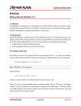
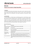
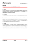
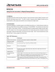
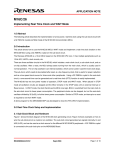
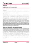
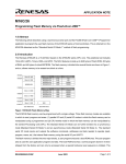
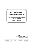
APPLICATION NOTE
M16C/26
Using Key Input Interrupts
1.0 Abstract
The following article introduces and shows how to setup key input interrupt on the M16C/26 (M30262) Flash
microcontroller (MCU). A sample program was written for the MSV-Mini26-SKP for evaluation purposes.
2.0 Introduction
The Renesas M16C/26 is a 16-bit MCU with multiple peripheral functions including handling interrupts generated
by several sources. One of the interrupt sources is the key input interrupt.
Key input interrupts can be used to ‘wake-up’ the M16C/26 from Wait or Stop Mode. Key input interrupts can be
used as alternative to monitor changes in the input pins (i.e. use an interrupt instead of polling the input pins for
changes). It can be used as additional external interrupt pins for applications with interrupt sources more than the
five external interrupt pins available on the M16C/26.
3.0 Key Input Interrupt Pins
The M16C/26 has four available key input pins that can be found on the upper four bits of Port 10 (P10_7, P10_6,
P10_5, & P10_4). These four pins have other functions: GPIO (General Purpose Input/Output) and analog inputs
to the internal AD converter. A block diagram of Port 10 is shown in Figure 1.
Figure 1 Port 10 Block
REU05B0052-0100Z
June 2003
Page 1 of 7
M16C/26
Using Key Input Interrupts
How the pins function is defined by setting special function registers in the M16C/26. We will focus on how to
setup and use these pins to generate key input interrupts. The two registers, Port 10 Direction Register (pd10 –
0x3F5) and Key Input Interrupt Control Register (kupic – 0x04D), needed to setup key input interrupts are shown
in Figure 2 and Figure 3. A diagram of key input interrupt block is shown in Figure 4.
Figure 2 Port 10 Direction Register, PD10
Figure 3 Key Input Interrupt Control Register, kupic
REU05B0052-0100Z
June 2003
Page 2 of 7
M16C/26
Using Key Input Interrupts
Figure 4 Key Input Interrupt Block
3.1 Key Input Interrupt Setup
As described earlier, M16C/26 registers are set to define how the upper four pins of Port 10 will function. To
setup the pins for key input interrupt function, the following must be set:
• The pins used for the key input interrupt must be set as inputs in the Port 10 direction register, PD10.
• The key input interrupt (and global interrupt) must be enabled.
If the key input interrupt (or the global interrupt) is disabled, the pins become general purpose inputs. To enable
it, an interrupt priority level (from 1 to 7) must be given to key input interrupt control register, kupic. The FSET I
instruction must be executed to enable global interrupts. Take note that interrupts are disabled by default after
reset. Refer to Interrupt Handler application note for details (see Reference).
3.2 Notes on Using the Key Input Interrupt Function
Setting up and using key input interrupts can be implemented easily. However, we need to mention a few notes
when using it.
The default state of key inputs is high (at least 0.8Vcc according to M16C/26 datasheet). A key input interrupt is
generated on the falling edge (high -> low transition) of one of the inputs. If one of the key inputs is always low, a
key input interrupt will not be generated.
As with any interrupt, the vector address for the key input interrupt must also be set so the MCU knows the
routine to process when the interrupt occurs. The interrupt vector is set in the sect30.inc startup file during
firmware development. Refer to Interrupt Handler application note for details (see Reference).
REU05B0052-0100Z
June 2003
Page 3 of 7
M16C/26
Using Key Input Interrupts
4.0 Key Input Interrupt Sample Program
A sample program was written for the MSV-Mini26-SKP Board as an example. The Red and Green LED’s are
turned on every time a key input interrupt is generated (i.e. when pushbutton S2 is pressed). Releasing the
pushbutton switch turns off the LED’s. To get a copy of the sample program, contact your Renesas
representative.
5.0 Conclusion
Key input interrupts can be used in a lot of applications. Setting up and using the function can be easily
implemented on the M16C/26.
6.0 Reference
Renesas Technology Corporation Semiconductor Home Page
http://www.renesas.com
E-mail Support
[email protected]
Data Sheets
• M16C/26 datasheets, M30262eds.pdf
User’s Manual
• M16C/20/60 C Language Programming Manual, 6020c.pdf
• M16C/20/60 Software Manual, 6020software.pdf
• Interrupt Handler App Note, M16C26_Interrupt_Handlers_in_C.doc
• MSV30262-SKP Users Manual, Users_Manual_Mini26B.pdf
REU05B0052-0100Z
June 2003
Page 4 of 7
M16C/26
Using Key Input Interrupts
7.0 Software Code
The key input interrupt sample program is shown below. The complete project, written in C, can be
compiled/linked using KNC30 Compiler and will be provided upon request. Please contact your Renesas
representative for details.
/*****************************************
* Mini 26 Rev. B Key Input Irq Program *
* main.c
*
* v1.0 03/06/2003
*
*****************************************/
/************************************************************************
* This Key Input Irq Program shows how to setup key input interrupts
*
* on the M16C/26. The program was written for the Mini 26 board.
*
*
*
* The program is simple: blink LEDs every time an interrupt occurs.
*
***********************************************************************/
/* Include the required header files */
#include "..\common\sfr262.h" // M16C/26 special function register definitions
/* Interrupt routines used for this demo must be defined with #pragma INTERRUPT as
shown below. Vectors must also be set in sect30_keyinirq.inc startup file to
point to the interrupt routine. */
#pragma INTERRUPT ki_irq
/* Function prototypes */
void ki_irq(void);
/* General definitions */
#define ON 0
#define OFF 1
/*****************************************************************************
Name:
Main - main program loop
Parameters:
None
Returns:
None
Description: Handles processing and contains the infinite loop while waiting for
key input interrupt.
*****************************************************************************/
main(){
/* To use key input interrupts, the port direction where the key inputs
are must be configured as inputs. The M16C/26 has 4 key inputs which can
be found on the upper 4 bits of port 10 (P10_7, P10_6, P10_5, P10_4).
We will set the direction for these 4 pins as inputs by setting it to 0.
On the Mini 26 Board, only P10_7 is used. P10_7 is connected to
pushbutton S2. The other 3 pins (P10_6, P10_5, & P10_4) are unused.
REU05B0052-0100Z
June 2003
Page 5 of 7
M16C/26
Using Key Input Interrupts
On the MSV30262 SKP Board, P10_7, P10_6, & P10_5 are
connected to S4, S3, & S2 respectively. P10_4 is not used.
The lower 4 bits are don't cares and can be set to inputs or outputs
depending on your hardware connection to these 4 pins. In our example,
P10_0 & P10_1 are set as inputs because on the Mini 26 and MSV30262
SKP Boards, these are used as ADC inputs. Ports P10_2 & P10_3 are unused
and we set these as outputs. */
pd10 = 0x0C;
/* 00001100;
Ports 10_7, 10_6, 10_5, 10_4 as inputs, where the
||||||||
key inputs are. Ports 10_3, 10_2, 10_1, 10_0 are
||||||||
don't cares. In our example, we set these to outputs.
||||||||
||||||||______P10_0, don't care - set to 0 (input)
|||||||_______P10_1, don't care - set to 0 (input)
||||||________P10_2, don't care - set to 1 (output)
|||||_________P10_3, don't care - set to 1 (output)
||||__________P10_4 (key input 0), set to 0 (input)
|||___________P10_5 (key input 1), set to 0 (input)
||____________P10_6 (key input 2), set to 0 (input)
|_____________P10_7 (key input 3), set to 0 (input) */
/* The next program step is not necessary as long as the pins are held at
a high level when not generating a key input irq.
On the MSV30262-SKP, the 3 inputs are held high with external pull-up
resistors and so, the step can be omitted.
On the Mini 26 Board, there is no external pull-up for pushbutton S2, and
so enable the internal pull-up for the upper bits of port 10. Again this
is only for the Mini 26 Board.
pu25 = 1;
*/
// enable internal pull-up for upper 4 bits of P10
/* We need to enable the key input interrupt. To accomplish this, we set
the key input interrupt control register to a non-zero value ranging from
1 to 7. The value you set controls the software interrupt priority level
- 1 (lowest) and 7 (highest).
*/
/* Initialize LED ports so we can use it for this demo */
pd7 |= 0x07;
// initialize LED's ports to outputs
p7 |= 0x07;
// turn off LED's
asm("FCLR I");
kupic = 2;
asm("FSET I");
while(1){
p7 |= 0x07;
}
//
//
//
//
disable interrupts before changing irq registers
enable key input irq by setting to non-zero value,
2 (interrupt priority level 2)
enable interrupts
// infinite loop
// turn off LED's while waiting for key input irq
}
REU05B0052-0100Z
June 2003
Page 6 of 7
M16C/26
Using Key Input Interrupts
/*****************************************************************************
Name:
ki_irq
Parameters:
None
Returns:
None
Description: This is an key input interrupt routine - processing when a key
interrupt is generated. A key input interrupt is generated when
one of the 4 pins goes to a low level.
NOTE: If one of the 4 inputs is always low, a key input interrupt
is NOT generated. It is generated by the falling edge (high->low)
of one of the key inputs.
For this demo on the Mini 26 Board, the key input interrupt is
generated when pushbutton S2 is pressed.
The routine turns Red and Green LEDs.
*****************************************************************************/
void ki_irq(void){
p7 = 0x02;
// turn on Red and Green LEDs
while(p10_7==0);
// wait here until pushbutton is released
}
REU05B0052-0100Z
June 2003
Page 7 of 7
Keep safety first in your circuit designs!
• Renesas Technology Corporation puts the maximum effort into making semiconductor products
better and more reliable, but there is always the possibility that trouble may occur with them. Trouble
with semiconductors may lead to personal injury, fire or property damage.
Remember to give due consideration to safety when making your circuit designs, with appropriate
measures such as (i) placement of substitutive, auxiliary circuits, (ii) use of nonflammable material or
(iii) prevention against any malfunction or mishap.
Notes regarding these materials
• These materials are intended as a reference to assist our customers in the selection of the Renesas
•
•
•
•
•
•
•
Technology Corporation product best suited to the customer's application; they do not convey any
license under any intellectual property rights, or any other rights, belonging to Renesas Technology
Corporation or a third party.
Renesas Technology Corporation assumes no responsibility for any damage, or infringement of any
third-party's rights, originating in the use of any product data, diagrams, charts, programs, algorithms,
or circuit application examples contained in these materials.
All information contained in these materials, including product data, diagrams, charts, programs and
algorithms represents information on products at the time of publication of these materials, and are
subject to change by Renesas Technology Corporation without notice due to product improvements
or other reasons. It is therefore recommended that customers contact Renesas Technology
Corporation or an authorized Renesas Technology Corporation product distributor for the latest
product information before purchasing a product listed herein.
The information described here may contain technical inaccuracies or typographical errors.
Renesas Technology Corporation assumes no responsibility for any damage, liability, or other loss
rising from these inaccuracies or errors.
Please also pay attention to information published by Renesas Technology Corporation by various
means, including the Renesas Technology Corporation Semiconductor home page
(http://www.renesas.com).
When using any or all of the information contained in these materials, including product data,
diagrams, charts, programs, and algorithms, please be sure to evaluate all information as a total
system before making a final decision on the applicability of the information and products. Renesas
Technology Corporation assumes no responsibility for any damage, liability or other loss resulting
from the information contained herein.
Renesas Technology Corporation semiconductors are not designed or manufactured for use in a
device or system that is used under circumstances in which human life is potentially at stake. Please
contact Renesas Technology Corporation or an authorized Renesas Technology Corporation product
distributor when considering the use of a product contained herein for any specific purposes, such as
apparatus or systems for transportation, vehicular, medical, aerospace, nuclear, or undersea
repeater use.
The prior written approval of Renesas Technology Corporation is necessary to reprint or reproduce in
whole or in part these materials.
If these products or technologies are subject to the Japanese export control restrictions, they must be
exported under a license from the Japanese government and cannot be imported into a country other
than the approved destination.
Any diversion or reexport contrary to the export control laws and regulations of Japan and/or the
country of destination is prohibited.
Please contact Renesas Technology Corporation for further details on these materials or the
products contained therein.