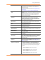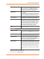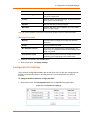
1
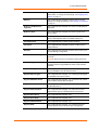
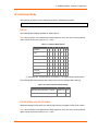
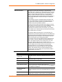
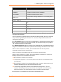
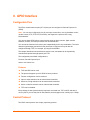
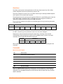
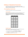
Guidelines
The GPIO control protocol is described from the PC side. Send means from PC to XPort
module. Response comes from XPort device server to PC.
The protocol allows for control of up to 32 GPIOs. How many are actually available depends
on the product. XPort module has only three.
The parameters are four bytes long and represent GPIOs 0-31, with GPIO0 in bit 0 of the first
byte (Little Endian). Parameter bits for configurable pins not configured as GPIOs are
undefined for Get commands and ignored on Set commands.
Every command consists of nine bytes: one command type of one byte and two parameters
of four bytes each.
Command
Parameter 1
0
1
2
3
Parameter 2
4
5
6
7
8
On some commands, one or all parameters are ignored.
For UDP, command type and parameters need to be in the same datagram.
Responses to valid commands are always five bytes long, consisting of the returned
command byte and as parameters in the current or updated values. In case of an invalid
command, only one byte with value 0FFh is returned.
Command
0
Parameter 1
1
2
3
4
When sending a command (TCP and UDP), wait for the response before sending the next
command.
Commands
Byte 0 Command Types
10h
Get functions
11h
Get directions (input or output)
12h
Get active levels (high active or low active)
13h
Get current states (active or not active)
19h
Set directions
1Ah
Set active levels
1Bh
Set current states
There is no Set functions command. Since the pin’s function depends on the hardware in
which the XPort unit is embedded, that configuration is only allowed using 77FE. Settings
changed by any of the Set commands are not stored and are lost when the unit is powered
down or rebooted.
XPort® Device Server User Guide
78