1
Plug-in Switch Module • Installation Guide
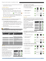
1. Using a level and a pencil, lightly mark two small dots to
align the upper edge of the module on the wall where you
want to mount it.
TIP: For easy housekeeping, provide sufficient clearance for
vacuum cleaners.
2. Slide the mounting plate off the
back of the module.
About the Setup Interface
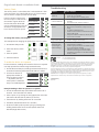
The setup interface has two buttons, Menu and Set, that each
have a corresponding 3-color LED (green, amber, red). This simple interface is used to link and configure devices as a system.
The buttons and LEDs are used to navigate and select linking
and setup options through a 3-tier menu system consisting of
different Modes > Menus > Options.
To use the interface, hold the module so both thumbs can click
the buttons without obscuring the LEDs. The illustration and
legend below describe how the buttons are used and the meaning of the LED responses.
3. With the tab lock side down,
mount the plate securely to the
wall.
A. Using the pencil marks to enunting
i screw
crew
rew
ew d
drill
rill
ill poi
p
ints.
sure it’s level, mark the two mounting
points.
To exit from anywhere in a menu, hold both buttons at the same
time for 2 seconds.
ho
ors with
h a 3/16” d
drill
rill bit
ri
ril
rill
B. Drill two holes for the wall anchors
and insert the wall anchors.
C. Insert the first screw loosely
and level the module.
D. Insert the second screw, and
then hand tighten the first
screw.
4. Slide module onto the mounting
plate until it clicks in place.
NOTE: Any EnOcean-based switch
can be linked to the module.
The Menu LED or Set LED display solid for a number of seconds in a certain color to indicate a mode or a confirmation.
The Menu LED blinks a number of times in a color to indicate a selected menu.
The Set LED blinks a number of times in a color to indicate
an option.
Linking
Two or more compatible devices can be linked and configured
to provide the desired control. There are two basic types of
devices in the system; transmitters and transceivers.
A number in a white box indicates the number of times to
click the Menu button or Set button.
A number in a black box indicates the number of seconds to
hold down the Menu button or Set button.
▪ Transmit-only: Transmitters are simple energy-harvesting
devices that send RF messages to communicate a condition,
level, or state. Transmitters can only be linked to transceivers.
Examples > Self-powered Light Switches, Occupancy Sensors
▪ Transmit & Receive: Transceivers are controlling devices
that send as well as receive RF messages. They also process
relevant control logic, and actuate the appropriate outputs
(switching a light on or off for example). Transceivers can be
linked with transmitters as well as other transceivers. A transceiver can have up to 30 devices linked to it.
Examples > Relays, Gateways
The Plug-In Switch Module is a Transceiver
(transmits & receives)
To link the occupancy sensor to a transceiver; the transceiver
must first be powered, within wireless range of the controls it is
to be linked to, and set to accepts links.
To link a transmitter to a transceiver
1. Access Basic Setup mode.
NOTE: By default, the Accept Link option in the Linking
menu is selected. Once activated, this option stays active for
two minutes to provide time to link multiple devices.
Ready to accept links.
2. For the transmitter to be linked, do one of the following according to the type of device:
A. Sensor: click the designated link button.
B. Key Card Switch: insert/remove the card 3 times quickly.
C. Rocker Pad: click the top button 3 times quickly.
Next, the desired transmitter, or another transceiver, is triggered
to send a special link message. The awaiting transceiver receives
and stores the link permanently so the devices can interact to
provide a variety of intelligent control options.
Device linked successfully.
Set LED displays solid
green for 3 seconds.
Ready to accept new links.
© 2013 Hubbell Building Automation
|
www.hubbell-automation.com
Page 2