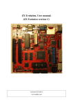
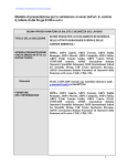
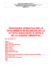
1
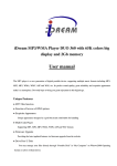
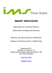
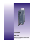
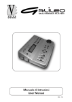
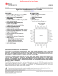
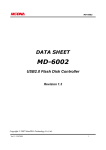
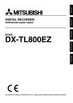
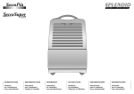
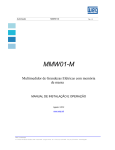
SAM2695 LOW POWER SINGLE CHIP SYNTHESIZER WITH EFFECTS AND BUILT-IN CODEC Single chip all-in-one design. o MIDI control processor, serial and parallel interface o Synthesis, General MIDI wavetable implementation o General MIDI compatible effects: reverb + chorus o Spatial Effect o 4-band stereo equalizer o Stereo DAC. DR: 86dB typ, THD+N: -75dB typ o Mike input. DR: 86dB typ, THD+N: -75dB typ o Mike echo State of the art synthesis for best quality/price products o 64-voice polyphony (without effects) o 38-voice polyphony + effects o On-chip CleanWave™ wavetable data, firmware, RAM delay lines Audio stereo line output. Typical applications: battery operated musical keyboards, portable phones, karaokes. QFN48 (6 x 6mm) package: small footprint, small pin count Low power o 18 mA typ Operating / 17 µA typ Power down o Single 3.3V power supply MIDI IN SAM2695 Audio Out Parallel MIDI Typical hardware configuration Cited trademarks belong to their respective owners, General MIDI logo under license of MIDI Manufacturers Association © 2013-2014 DREAM S.A.S. FRANCE - All rights reserved SAM2695 1- PIN DESCRIPTION 1-1- PINS BY FUNCTION – 48-lead QFN Package - 5VT indicates a 5 volt tolerant Input or I/O pin. DR4, DR8 indicates driving capability at VOL, VOH (see § 4- D.C. CHARACTERISTICS) Power supply group Pin name GND GND VD33 Pin # 9, 13, 18, 25, 36, 45, 48 exposed die pad AGND 8, 11, 20, 31, 35, 41, 46 4 VA33 6 Type Description PWR DIGITAL GROUND All pins should be connected to a ground plane PWR DIGITAL GROUND Ground supply; down bonded to the exposed die pad (heatsink). It is recommended, but not obligatory, to connect this pad to a ground plane during PCB layout PWR PERIPHERY POWER SUPPLY (+2.7V to 3.6V) All VD33 pins should be returned to nominal +3.3V. PWR ANALOG GROUND This pin should be connected to an analog ground plane PWR CODEC PERIPHERY ANALOG SUPPLY This pin should be connected to a nominal 3.3V power through a serial inductor filter (better result) or a 10 ohm resistor. Serial MIDI, parallel MIDI Pin name MIDI_IN D0-D7 Pin # 16 Type IN-5VT A0 24, 26-30, 32, 33 10 I/O IN-5VT CS/ 14 IN-5VT RD/ 15 IN-5VT WR/ 12 IN-5VT IRQ 42 OUT-DR4 -5VT-DR8 Description Serial TTL MIDI IN. Connected to the built-in synthesizer at power-up. This pin has a built-in pull up. It should be left open or tied HIGH if not used. 8-bit data bus to host processor. Information on these pins is parallel MIDI Select data(0) or control(1) for write, data(0) or status(1) for read. Chip select, active low. This pin has a built-in pull up. It should be left unconnected if not used. Read, active low. When CS/ and RD/ are low, data (A0=0) or status (A0=1) is read on D0-D7. Read data is acknowledged on the rising edge of RD/. Write, active low. When CS/ and WR/ are low, data (A0=0) or control (A0=1) is written from the D0-D7 bus to the SAM2695 on the rising edge of WR/. A rising edge indicates that a MIDI byte is available for read on D0-D7. Acknowledged by reading the byte. Analog audio group Pin name MICIN AOUTL AOUTR VCM 7 1 2 5 Pin # Type IN OUT OUT OUT VCMHPOUT 3 OUT Description Analog microphone input. Left channel audio line or headphones output Right channel audio line or headphones output Analog common-mode voltage. Should be stabilized by external capacitors 10µF // 100nF to AGND. Analog headphones common-mode voltage buffer output. 2 SAM2695 Miscellaneous group Pin name RST/PD/ X1-X2 XDIV OUTVC12 TEST NC Pin # Type Description IN-5VT Master reset and Power down. Schmitt trigger input. RST/PD/ should be held low during at least 10ms after power is applied. On the rising edge of RST/PD/ the chip enters its initialization routine. When RST/PD/ is low, Power-down is active: 8-bit port data lines are High-Z. IRQ is set to 0. The PLL is stopped and supply voltage is removed from analog and digital core. To exit from power down, RST/PD/ must be set to VD33. 39, 40 9.6 MHz or 12 MHz crystal connection. An external clock can also be used on X1. 47 IN System clock divider. - When grounded, it allows using 9.6MHz crystal - When connected to VD33, it allows using 12MHz crystal 34 PWR 3.3V to 1.2 V regulator output. The built-in regulator gives 1.2V for internal use only (core supply). 4.7µF or 10µF Decoupling capacitor must be connected between OUTVC12 and GND. 37 IN Test pin with a built-in pull-down. It should be grounded or left open for normal operation. 17, 19, 21-23; Not connected pins. 43, 44 38 1-2- PINOUT BY PIN # - 48-lead QFN Package Pin# 1 2 3 4 5 6 7 8 9 10 11 12 Signal Name AOUTL AOUTR VCMHPOUT AGND VCM VA33 MICIN VD33 GND A0 VD33 WR/ Pin# 13 14 15 16 17 18 19 20 21 22 23 24 Signal Name GND CS/ RD/ MIDI_IN NC GND NC VD33 NC NC NC D0 Pin# 25 26 27 28 29 30 31 32 33 34 35 36 Signal Name GND D1 D2 D3 D4 D5 VD33 D6 D7 OUTVC12 VD33 GND Pin# 37 38 39 40 41 42 43 44 45 46 47 48 Signal Name TEST RST/PD/ X1 X2 VD33 IRQ NC NC GND VD33 XDIV GND 3 SAM2695 1-3- MECHANICAL DIMENSIONS – 48-lead MQFN Package ZI 21140 Semur-en-Auxois FRANCE TITLE 48 LD MQFN (6x6mm) Package Outline L/F Material: A194 FH Package designation REV. MQFN48 4 SAM2695 1-4- MARKING FRANCE SAM2695 XXXXX-XXX • YYWW Pin 1 5 SAM2695 2- ABSOLUTE MAXIMUM RATINGS (All voltages with respect to 0V, GND=0V)* Parameter Temperature under bias Storage temperature Voltage on any 5 volt tolerant pin (5VT) Voltage on any non-5 volt tolerant pin Supply voltage (I/O) Supply voltage (CODEC analog 3.3V) Symbol VD33 VA33 Min -55 -65 -0.3 -0.3 -0.3 -0.3 Typ - Max +125 +150 5.5 VD33+0.3 3.6 3.6 Unit °C °C V V V V *NOTICE: Stresses beyond those listed under “Absolute Maximum Ratings” may cause permanent damage to the device. This is a stress rating only and functional operation of the device at these or any other conditions beyond those indicated in the operational sections of this specification is not implied. Exposure to absolute maximum rating conditions for extended periods may affect device reliability. 3- RECOMMENDED OPERATING CONDITIONS Parameter Digital supply voltage Analog supply voltage (CODEC) Operating ambient temperature Symbol VD33 VA33 tA Min 2.7 2.7 -25 Typ 3.3 3.3 - Max 3.6 3.6 +70 Unit V V °C 4- D.C. CHARACTERISTICS (TA=25°C, VD33=3.3V, X1=12 MHz, AOUTL/AOUTR load = 47kΩ) Parameter Low level input voltage High level input voltage on 5VT pins High level input voltage on non 5VT pins Low level output voltage at IOL = IOHL Min High level output voltage at IOH = IOHL Min Schmitt-trigger negative-to-threshold voltage Schmitt-trigger positive-to-threshold voltage Driving capability at VOL, VOH for DR4 pins Driving capability at VOL, VOH for DR8 pins Input leakage current OUTVC12 output voltage Digital power supply current Analog power supply current Power down supply current Pull-up, Pull-down or Keeper resistor Symbol VIL VIH VIH VOL VOH VTN VTP IOHL IOHL IIN VD12 ID33 IA33 Rudk Min 2 2 2.4 0.8 -10 1.14 30 Typ 1.1 1.6 ±1 1.2 10 8 17 75 Max 0.8 0.4 2 4 8 10 1.26 190 Unit V V V V V V V mA mA µA V mA mA µA kΩ 6 SAM2695 5- DAC. CHARACTERISTICS (TA=25°C, VA33=3.3V) Parameter Total Harmonic Distortion + Noise (at - 6 dB) Dynamic Range (-60dBFS with A-Weighted) Inter-channel isolation (1kHz) Full-scale output voltage VCM Maximum allowable DC current source VCM Reference voltage (with 10µF and 100nF capacitors) Output Gain Control - 1dB steps - Additional setting 1 - Additional setting 2 Maximum output power in Headphones mode Symbol THD + N Min - Typ -75 Max - Unit dB DR - 89 VA33 ÷ 2 – 50mV 86 0.85*VA33 VA33 ÷ 2 0.1 VA33 ÷ 2 + 50mV dB dB Vpp mA V +6 dB dB dB mW -40 -43.5 -58.5 - 30 6- ADC. CHARACTERISTICS (TA=25°C, VA33 = 3.3V) Parameter Total Harmonic Distortion + Noise (at - 6 dB) Dynamic Range (-60dBFS with A-Weighted) Full-scale input voltage Input Gain without boost Input Gain with boost Input Programmable Gain Amplifier (1dB steps) Frequency response ( -3dB bandwidth) MICIN input resistance with boost disabled MICIN input resistance with boost enabled Symbol THD + N Min - Typ - 75 DR - - 86 0.6*VA33 +4 +24 +22 -27 0.41 Max -70 +36 35 3.5 Unit dB dB Vpp dB dB dB Fs kOhm kOhm 7 SAM2695 7- TIMINGS 7-1- SLAVE 8-BIT PARALLEL INTERFACE This interface is typically used to connect the chip to an host processor. A0 ta v c s CS/ tc s lr d l RD/ tp r d tr d h c s h tr d ld v td r h D 0 -D 7 IR Q 8 - b it p a r a lle l in t e r f a c e r e a d c y c le tw r c y c A0 ta v c s CS/ tc s lw r l tp w r tw r h c s h W R/ td w s td w h D 0 -D 7 8 - b it p a r a lle l in t e r f a c e w r it e c y c le Parameter Address valid to chip select low Chip select low to RD/ low RD/ high to CS/ high RD/ pulse width Data out valid from RD/ Data out hold from RD/ Chip select low to WR/ low WR/ high to CS/ high WR/ pulse width Write data setup time Write data hold time Write cycle Symbol tavcs tcslrdl trdhcsh tprd trdldv tdrh tcslrwrl twrhcsh tpwr tdws tdwh twrcyc Min 0 5 5 50 5 5 5 50 10 0 3.5 Typ - Max 20 10 - Unit ns ns ns ns ns ns ns ns ns ns ns µs Notes: - When data is pending on parallel port, the host should read it within 1 ms. If not, the parallel port will be deactivated. Reactivating the port can be done with the following control sequence: 0FFh (Closed port), 03Fh (Open port). - For safe operation, write cycle time should not be lower than 3.5µs. 8 SAM2695 8- RESET AND POWER DOWN During power-up, the RST/PD/ input should be held low during 10ms. A typical RC/diode power-up network can be used. After the low to high transition of RST/PD/, the SAM2695 enters an initialization routine. It takes around 50 ms before a MIDI IN or MPU message can be processed. Audio will begin after 500 ms, maximum. If RST/PD/ is asserted low then the crystal oscillator and PLL will be stopped. The chip enters a deep power down sleep mode, as power is removed from the core. To exit power down, RST/PD/ has to be asserted high. 8-1- PIN STATUS IN POWER-DOWN Table below shows the status of each pin in Normal mode (RST/PD/ High) and in Powerdown mode (RST/PD/ Low) Pin MIDI IN CS/ RD/ WR/ IRQ A0 D[7:0] LHPOUT RHOUT VCMHPOUT VCM MICIN RST/PD/ X1 – X2 XDIV TEST Status in Normal mode IN with Pull-up resistor IN IN IN OUT IN I/O ANA OUT ANA OUT ANA OUT ANA OUT ANA IN IN Oscillator IN IN with Pull-down resistor Status in Power-down mode IN with Keeper resistor IN (floating) IN (floating) IN (floating) OUT – Low Level IN with Keeper resistor IN (floating) ANA OUT – VCM Level ANA OUT – VCM Level ANA OUT – VCM Level ANA OUT – VCM Level ANA IN IN driven Low Power-down IN with Keeper resistor IN with Pull-down resistor Note: - Keeper resistor can be pull-up or pull-down resistor. This depends on logic state at the pin where it is connected when switching to Power-down mode. o If logic state is ‘Low’ when entering Power-down mode, keeper resistor will be pull-down o If logic state is ‘High’ when entering Power-down mode, keeper resistor will be pull-up - In a designs where it is planned to use the Power-down mode, external pull up or pull down resistor should be added on each pin that have the “IN (floating)” status and that is not externally driven in Power-down mode. To avoid consumption in Normal mode these resistors can have high value like 1MOhm. 9 SAM2695 9- RECOMMENDED CRYSTAL COMPENSATION 10- ANALOG INPUT AND OUTPUTS The schematics of this section are the reference designs for SAM2695 analog input and outputs. The conformity with these schematics ensures the best performances. 10-1- LINE OUTPUT 10-2- HEADPHONES OUTPUT 10 SAM2695 10-3- HEADPHONES OR LINE OUTPUT 10-4- MICROPHONE INPUT 11 SAM2695 11- RECOMMENDED BOARD LAYOUT Like all HCMOS high integration ICs, following simple rules of board layout is mandatory for reliable operations: GND, VD33, VA33 distribution and decoupling All GND, VD33, VA33 pins should be connected. A GND plane is strongly recommended below the SAM2695. The board GND, VD33, distribution should be in grid form. Recommended decoupling is 4.7 or 10µF close to OUTVC12 pin. Each VD33 and VA33 pin requires 0.1µF. An additional 10µF-T capacitor should be placed on VD33, close to the crystal. Decoupling capacitors should be implemented close to the IC. Crystal The paths between the crystal, the crystal compensation capacitors and the SAM2695 should be short and shielded. The ground return from the compensation capacitors should be the GND plane from SAM2695. D0-D7 Bus A ground plane should be implemented below the D0-D7 bus, which connects both to the host and to the SAM2695 GND. Analog section A specific AGND ground plane should be provided, which connects by a single trace to the GND ground. No digital signals should cross the AGND plane. 12 SAM2695 SAM2695 USER’S MANUAL 1- PARALLEL AND SERIAL MIDI MODES The SAM2695 can be controlled both from the parallel interface (D0-D7, CS/, WR/, RD/, INT) or from the serial MIDI interface (MIDI IN). The parallel Interface consists of two byte registers and one IRQ (interrupt request) line: I/O address A0 = 0 A0 = 1 Write from host DATA8 CONTROL Read to host DATA8 STATUS Status Register TE RF X X X X X X TE: Transmit empty. If 0, data from SAM2695 to host is pending and IRQ is high. When host is reading the data in DATA8 register (A0 = 0), TE goes to1 and IRQ is low again. RF: Receiver full. If 0 then SAM2695 is ready to accept CONTROL or DATA from host. However, minimum time between two consecutive writes must be 3.5 µs (even if RF is not set). 1-1- SERIAL & PARALLEL MODES Serial mode: After power-up, hardware reset or parallel reset control, the SAM2695 is in serial mode: In this mode, the parallel MIDI interface is inactive and the IRQ line is floating. The serial MIDI IN is connected to the synthesis. In serial mode, the 8-bit parallel interface accepts two controls: 3Fh to switch to parallel mode SAM2695 is acknowledging 3Fh control by sending to host FEh in DATA8 register. BEh to send any control (see list of control message in chapter 2-2). BEh allows to send only one control, which means that each control sent in serial mode should start with BEh control. Parallel mode: In parallel mode, all data received by SAM2695 on its serial MIDI IN pin is sent to host through the 8-bit register DATA8 but is not sent to synthesis. Midi Data received by SAM2695 from host through register DATA8 is sent to the synthesis. Parallel mode accepts following controls: FFh (parallel mode reset) switch back to serial mode. Additional controls listed in paragraph 2.2. These additional controls, being independent of the MIDI data flow, allow to easily insert some special messages (for controlling some SAM2695 effect modules), in the middle of a MIDI data flow. 13 SAM2695 The following diagram illustrates serial and parallel mode: DATA8 IN (from Host) SYNTHESIS Serial MIDI IN DATA8 OUT (to Host) Serial Mode DATA8 IN (from Host) SYNTHESIS Serial MIDI IN DATA8 OUT (to Host) Parallel Mode 14 SAM2695 2- CONFIGURATION AND SPECIAL MESSAGES SAM2695 includes the following modules: 4-band Equalizer, Chorus effect, Reverb effect, Spatial effect, Mike input, Mike Echo. Some special messages allow to set parameters for these modules. Messages have two formats: - NRPN or SysEx midi messages: this format can be use either in serial mode or in parallel mode - Parallel controls: this format should be used in parallel mode only. 2-1 SPECIAL MIDI MESSAGES (received on serial MIDI in serial mode or on 8-bit data port in parallel mode) Special midi messages are sent using midi Nrpn messages. These NRPN messages are mainly using NRPN high=037h. For example, master volume can be set using NRPN "3707h", which means: - NRPN high = 037h: midi control 99 (63h) = 55 (37h) --> midi message = 0B0h 063h 037h - NRPN low = 07h: midi control 98 (62h) = 07 (07h) --> midi message = 0B0h 062h 07h - NRPN value=vv: midi control 6 (06h) =vv ---> midi message = 0B0h 006h vv vv being master volume value in range 0 to 127 (0 to 7Fh). Here is below list of all special NRPNs. For controlling reverb/chorus, use standard reverb/chorus midi system exclusive messages listed in paragraph 3 "Detailed MIDI implementation". NRPN # (High|Low) 3700h 3701h 3702h 3703h 3707h 3708h 3709h 370Ah 370Bh 3713h 3715h 3716h 3718h 3719h 371Ah 3720h 3722h 3723h 3724h 3726h 3728h 3729h 372Ah 372Ch 372Dh 3730h 3731h 3732h 3733h Description Equalizer Low band (bass) Equalizer Med Low band Equalizer Med High band Equalizer High band (treble) Master Volume Equalizer Low cutoff freq Equalizer Med Low cutoff freq Equalizer Med High cutoff freq Equalizer High cutoff freq Clipping mode select General MIDI reverb send General MIDI chorus send Post effects applied on GM 0=-12dB, 40h=0dB, 7Fh=+12dB 0=-12dB, 40h=0dB, 7Fh=+12dB 0=-12dB, 40h=0dB, 7Fh=+12dB 0=-12dB, 40h=0dB, 7Fh=+12dB 0 to 7Fh 0=0Hz, 7Fh=4.7 kHz 0=0Hz, 7Fh=4.2 kHz 0=0Hz, 7Fh=4.2 kHz 0=0Hz, 7Fh=18.75 kHz 0=soft clip, 7Fh=hard clip 0=no send,40h=default send,7Fh=max 0=no send,40h=default send,7Fh=max 0= Post effects not applied (1) 7Fh=Post effects applied (1) Post effects applied on Mike 0= Post effects not applied (1) 7Fh=Post effects applied (1) Post effects applied on Reverb/Chorus 0= Post effects not applied (1) 7Fh=Post effects applied (1) Spatial Effect volume (2) 0= no effect, 7Fh= maximum effect General MIDI volume 0 to 7Fh General MIDI pan 0=left, 40h=center, 7Fh=right Mike volume 0 to 7Fh Mike pan 0=left, 40h=center, 7Fh=right Mike Echo level 0 to 7Fh Mike Echo time 0=shortest to 7Fh=longest (380ms) Mike Echo feedback 0=no feedback to 7Fh=maximum feedback Spatial Effect delay (2) 0=shortest to 7Fh=longest Spatial Effect input (2) 0=stereo 7Fh=mono Slave1 Echo volume right 0 to7Fh (see appendix) Slave1 Echo volume left 0 to7Fh (see appendix) Slave2 Echo volume right 0 to7Fh (see appendix) Slave2 Echo volume left 0 to7Fh (see appendix) Power-up default 60h 40h 40h 60h 7Fh 0Ch 1Bh 72h 40h 00h 40h 40h 7Fh 00h 7Fh 00h 7Fh 40h 40h 40h 7Fh 2Bh 42h 1Dh 00h 00h 00h 00h 00h 15 SAM2695 3734h 3735h 3751h 3757h 375Fh Master Echo volume right 0 to7Fh (see appendix) Master Echo volume left 0 to7Fh (see appendix) Auto - test See section 7 System Exclusive Device ID 0 to 1Fh, 20h=all accepted Effect ON/OFF – Polyphony Select. See section 5 7Fh 7Fh 20h Notes: (1) Post effects are Spatial Effect + Equalizer (2) See Block diagram in Appendix SPECIAL MIDI MESSAGES DETAILS SYSTEM MESSAGES NRPN # CONTROL NAME (High|Low) 3707h MASTER_VOL Parameters (Data) Data (byte 0-7Fh,7Fh) Action Master volume - MASTER_VOL: Master volume. Data range : 0-7Fh. Default=7Fh. MIDI MESSAGES NRPN # CONTROL NAME (High|Low) 3722h GM_VOL 3723h GM_PAN Parameters (Data) -Data(byte 0-7Fh,7Fh) -Data(byte 0-7Fh,40h) Action General MIDI volume General MIDI pan - GM_VOL Range 0-7Fh, linear scale. Default value: GM_VOL=07Fh - GM_PAN 0=hard left, 40h=center, 7Fh=hard right. Same as GM system exclusive message « 40h 00h 06h » Default value: GM_PAN=40h SPATIAL EFFECT DEVICE See Block diagram in Appendix. NRPN # CONTROL NAME (High|Low) 3720h SUR_VOL 372Ch SUR_DEL 372Dh SUR_INP Parameters (Data) -Data(byte 0-7Fh,0) -Data(byte 0-7Fh,1Dh) -Data(byte 0/7Fh,0) - SUR_VOL: Spatial Effect volume. Default=0 - SUR_DEL: Delay time Default=1Dh - SUR_INP: Input type select 0 Stereo (default), Stereo wide, 7Fh Mono, Pseudo stereo Action Spatial Effect volume Spatial Effect delay Input mono/stereo select for Spatial Effect Input to delay line is left - right. Input to delay line is left + right. 16 SAM2695 ROUTING MESSAGES NRPN # CONTROL NAME (High|Low) 3718h GM_POST 3719h MIKECH_POST 371Ah EFF_POST Parameters (Data) -Data(byte 0/7Fh,7Fh) -Data(byte 0/7Fh,00h) -Data(byte 0/7Fh,7Fh) Action Post effects applied on General MIDI Post effects applied on Mike and Echo Post effects applied on Reverb-chorus - xxx_POST: Post effects are Spatial Effect and Equalizer. Post effects can be separately applied on each module. However general settings of post effects (EQ_xxx, EQF_xxx, EQU_TYPE, SUR_VOL, SUR_DEL, SUR_INP) are common for all modules. Data = 00h: post effects not applied on module. Data = 7Fh: post effects applied on module. MIKE & ECHO DEVICE For these controls being effective, Mike and Echo must first be set ON using nrpn 375Fh. NRPN # (High|Low) 3724h 3726h 3728h 3729h 372Ah 3734h 3735h 3730h 3731h 3732h 3733h CONTROL NAME MIKE_VOL MIKE_PAN ECH_LEV ECH_TIM ECH_FEED ECHM_RIGHT ECHM_LEFT ECHS1_RIGHT ECHS1_LEFT ECHS2_RIGHT ECHS2_LEFT Parameters (Data) -Data(byte 0-7Fh,40h) -Data(byte 0-7Fh,40h) -Data(byte 0-7Fh,7Fh) -Data(byte 0-7Fh,2Bh) -Data(byte 0-7Fh,42h) -Data(byte0-7Fh,7Fh) -Data(byte0-7Fh,7Fh) -Data(byte0-7Fh,00h) -Data(byte0-7Fh,00h) -Data(byte0-7Fh,00h) -Data(byte0-7Fh,00h) Action Mike volume Mike pan Echo level Echo time (max 7Fh 380ms) Echo feedback Master Echo volume right Master Echo volume left Slave1 Echo volume right Slave1 Echo volume left Slave2 Echo volume right Slave2 Echo volume left - ECH_xxx : Controls for echo applied on Mike input. ECH_LEV: 0 to 07Fh (Default 7Fh) ECH_TIM: 0 =shortest to 7Fh=longest (default 2Bh) ECH_FEED: 0=no feedback, 7Fh=maximum feedback (default 42h) - ECHx_LEFT, ECHx_RIGHT : Pan Controls for echo. Default setting of Echo is a stereophonic triple echo: echo is heard successively in left speaker, then center, then right speaker. These controls allow to change stereophonic position of each of the 3 echos (left, right and center). For example, for having only a monophonic echo located in center, send: ECHS1_RIGHT=0, ECHS1_LEFT=0 (supress slave1 echo) ECHS2_RIGHT=0, ECHS2_LEFT=0 (supress slave2 echo) ECHM_RIGHT=7Fh, ECHM_LEFT=7Fh (main echo to maximum volume). See also appendix 8-4 for details. 17 SAM2695 EQUALIZER DEVICE NRPN # (High|Low) 3700h 3701h 3702h 3703h 3708h 3709h 370Ah 370Bh CONTROL NAME EQ_LB EQ_MLB EQ_MHB EQ_HB EQF_LB EQF_MLB EQF_MHB EQF_HB Parameters (Data) -Level (byte 0-7Fh,60h) -Level (byte 0-7Fh,40h) -Level (byte 0-7Fh,40h) -Level (byte 0-7Fh,60h) -Data (byte 0-7Fh,0Ch) -Data (byte 0-7Fh,1Bh) -Data (byte 0-7Fh,72h) -Data (byte 0-7Fh,40h) Action Equalizer low band Equalizer med low band Equalizer med high band Equalizer high band Equalizer low band frequency Equalizer med low band frequency Equalizer med high band frequency Equalizer high band frequency Band level EQ_xxx: 00h 20h 40h 60h 7Fh -12dB -6dB 0dB +6dB +12dB Default =60h (+6dB) for LB-HB, =40h(0dB) for MLB-MHB EQF_xxx: Band LB MLB MHB HB Range 0-4.7Khz 0-4.2Khz 0-4.2Khz 0-18.75Khz Band frequency (0-7Fh), linear scale Default 0Ch 1Bh 72h 40h 18 SAM2695 2-2- CONTROLS (received on parallel CONTROL register) Controls are normally sent in parallel mode. Individual controls can also be sent on 8-bit port in serial mode if preceded by control BEh. CONTROL MESSAGES OVERVIEW A control message consists of one CONTROL byte followed by one DATA8 byte (parameter). Ctrl # 7h 10h 11h 12h 13h 14h 15h 16h 17h 18h 19h 1Ah 1Bh 1Ch 1Dh 25h 26h 28h 29h 2Ah 2Bh 2Ch 2Dh 2Eh 30h 31h 32h 34h 36h 38h 39h 3Ah 3Bh 3Fh 62h Master Volume Equalizer low band left (bass) Equalizer med low band left Equalizer med high band left Equalizer high band left (treble) Equalizer low band right (bass) Equalizer med low band right Equalizer med high band right Equalizer high band right (treble) Equalizer Low cutoff freq Equalizer Med Low cutoff freq Equalizer Med High cutoff freq Equalizer High cutoff freq Main Echo right volume Main Echo left volume General MIDI reverb send General MIDI chorus send Mike Echo level Mike Echo time Mike Echo feedback Slave1 Echo right volume Slave1 Echo left volume Slave2 Echo right volume Slave2 Echo left volume Spatial Effect volume (2) Spatial Effect delay (2) Spatial Effect input (2) Mike volume Mike pan General MIDI volume General MIDI pan Reverb general volume Chorus general volume Switch to UART mode Post effects applied on GM 65h Post effects applied on Mike and Echo 66h Post effects applied on Reverb/Chorus 69h 6Ah 74h 75h Reverb program select Chorus program select Chorus delay Chorus feedback Description 0 to FFh 0=-12dB, 40h=0dB, 7Fh=+12dB 0=-12dB, 40h=0dB, 7Fh=+12dB 0=-12dB, 40h=0dB, 7Fh=+12dB 0=-12dB, 40h=0dB, 7Fh=+12dB 0=-12dB, 40h=0dB, 7Fh=+12dB 0=-12dB, 40h=0dB, 7Fh=+12dB 0=-12dB, 40h=0dB, 7Fh=+12dB 0=-12dB, 40h=0dB, 7Fh=+12dB 0=0Hz, 7Fh=4.7 kHz 0=0Hz, 7Fh=4.2 kHz 0=0Hz, 7Fh=4.2 kHz 0=0Hz, 7Fh=18.75 kHz 0 to 7Fh 0 to 7Fh 0=no send,80h=default send,FFh=max 0=no send,80h=default send,FFh=max 0 to 7Fh 0 to 7Fh 0 to 7Fh 0 to 7Fh 0 to 7Fh 0 to 7Fh 0 to 7Fh 0= no effect, FFh= maximum effect 0=shortest to 7Fh=longest 0=stereo 7Fh=mono 0 to FFh 0=left, 40h=center, 7Fh=right 0 to FFh 0=left, 40h=center, 7Fh=right 0 to FFh 0 to FFh 0= Post effects not applied (1) 7Fh=Post effects applied (1) 0= Post effects not applied (1) 7Fh=Post effects applied (1) 0= Post effects not applied (1) 7Fh=Post effects applied (1) 0 to 7h 0 to 7h Power-up default FFh 60h 40h 40h 60h 60h 40h 40h 60h 0Ch 1Bh 72h 40h 7Fh 7Fh 80h 80h 7Fh 2Bh 42H 00h 00h 00h 00h 00h 1Dh 00h 80h 40h FFh 40h (3) (3) Compatible NRPN/SYSEX Nrpn 3707h Nrpn 3700h Nrpn 3701h Nrpn 3702h Nrpn 3703h Nrpn 3700h Nrpn 3701h Nrpn 3702h Nrpn 3703h Nrpn 3708h Nrpn 3709h Nrpn 370Ah Nrpn 370Bh Nrpn 3734h Nrpn 3735h Nrpn 3715h Nrpn 3716h Nrpn 3728h Nrpn 3729h Nrpn 372Ah Nrpn 3730h Nrpn 3731h Nrpn 3732h Nrpn 3733h Nrpn 3720h Nrpn 372Ch Nrpn 372Dh Nrpn 3724h Nrpn 3726h Nrpn 3722h Nrpn 3723h SysEx 40h 01h 33h SysEx 40h 01h 3Ah 7Fh Nrpn 3718h 00h Nrpn 3719h 7Fh Nrpn 371Ah 04h 02h (3) (3) SysEx 40h 01h 30h SysEx 40h 01h 38h SysEx 40h 01h 3Ch SysEx 40h 01h 3Bh 19 SAM2695 76h Chorus rate 77h Chorus depth 78h Reverb time 79h Reverb feedback. Only if reverb number=6 or 7 (delays) 7Eh Clipping mode select 0=soft clip, 7Fh=hard clip BEh Enable Dream control in stand alone mode FFh Reset UART mode Notes: (1) Post effects are Spatial Effect + Equalizer (2) See Block diagram in Appendix (3) See CONTROL MESSAGES DETAILS (3) (3) (3) (3) 00h SysEx 40h 01h 3Dh SysEx 40h 01h 3Eh SysEx 40h 01h 34h SysEx 40h 01h 35h Nrpn 3713h CONTROL MESSAGES DETAILS SYSTEM MESSAGES Ctrl # 07h BEh FFh 3Fh CONTROL NAME MASTER_VOL EN_CONTROL RESET UART_MOD Parameters (Data) Data (byte 0-FFh,FFh) None None None Action Master volume Enable dream control in stand alone mode Reset UART mode Switch to UART mode Answer Data= FEh - MASTER_VOL: Master volume. Data range : 0-FFh. Default=FFh. - EN_CONTROL: This control has been implemented to enable to send any parallel control even in Serial mode. It allows to send only one parallel control, which means that each control sent in serial mode should start with EN_CONTROL control. - RESET: Switch SAM2695 in serial mode - UART_MODE: Switch SAM2695 in parallel mode 20 SAM2695 SPATIAL EFFECT DEVICE See Block diagram in Appendix. Ctrl # 30h 31h 32h CONTROL NAME SUR_VOL SUR_DEL SUR_INP Parameters (Data) -Data(byte 0-FFh,0) -Data(byte 0-7Fh,1Dh) -Data(byte 0/7Fh,0) - SUR_VOL: Spatial Effect volume. Default=0 - SUR_DEL: Delay time Default=1Dh - SUR_INP: Input type select 0 Stereo (default), Stereo wide, 7Fh Mono, Pseudo stereo Action Answer Spatial Effect volume Spatial Effect delay Input mono/stereo select for Spatial Effect Input to delay line is left - right. Input to delay line is left + right. ROUTING MESSAGES Ctrl # 62h 65h 66h CONTROL NAME GM_POST MIKECH_POST EFF_POST Parameters (Data) -Data(byte 0/7Fh,7Fh) -Data(byte 0/7Fh,00h) -Data(byte 0/7Fh,7Fh) Action Answer Post effects applied on general MIDI Post effects applied on Mike and Echo Post effects applied on Reverb-chorus - xxx_POST: Post effects are Spatial Effect and Equalizer. Post effects can be separately applied on each module. However general settings of post effects (EQ_xxx, EQF_xxx, EQU_TYPE, SUR_VOL, SUR_DEL, SUR_INP) are common for all modules. Data = 00h: post effects not applied on module. Data = 7Fh: post effects applied on module. MIDI MESSAGES Ctrl # 38h 39h CONTROL NAME GM_VOL GM_PAN Parameters (Data) -Data(byte 0-FFh,FFh) -Data(byte 0-7Fh,40h) Action Answer General MIDI volume General MIDI pan - GM_VOL Range 0-FFh, linear scale. Default value: GM_VOL=0FFh - GM_PAN 0=hard left, 40h=center, 7Fh=hard right. Same as GM system exclusive message « 40h 00h 06h » Default value: GM_PAN=40h 21 SAM2695 MIKE & ECHO DEVICE For these controls being effective, Mike and Echo must first be set ON using nrpn 375Fh. Ctrl # 34h 36h 28h 29h 2Ah 1Ch 1Dh 2Bh 2Ch 2Dh 2Eh CONTROL NAME MIKE_VOL MIKE_PAN ECH_LEV ECH_TIM ECH_FEED ECHM_RIGHT ECHM_LEFT ECHS1_RIGHT ECHS1_LEFT ECHS2_RIGHT ECHS2_LEFT Parameters (Data) -Data(byte 0-FFh,80h) -Data(byte 0-7Fh,40h) -Data(byte 0-7Fh,7Fh) -Data(byte 0-7Fh,2Bh) -Data(byte 0-7Fh,42h) -Data(byte0-7Fh,7Fh) -Data(byte0-7Fh,7Fh) -Data(byte0-7Fh,00h) -Data(byte0-7Fh,00h) -Data(byte0-7Fh,00h) -Data(byte0-7Fh,00h) Action Answer Mike volume Mike pan Echo level applied on Mike Echo time applied on Mike Echo feedback applied on Mike Main Echo volume right Main Echo volume left Slave1 Echo volume right Slave1 Echo volume left Slave2 Echo volume right Slave2 Echo volume left - ECH_xxx: Controls for echo applied on Mike input. ECH_LEV: 0 to 07Fh (Default 7Fh) ECH_TIM: 0 =shortest to 7Fh=longest (default 2Bh), longest 7Fh 380ms ECH_FEED: 0=no feedback, 7Fh=maximum feedback (default 42h) - ECHx_LEFT, ECHx_RIGHT: Pan Controls for echo. Default setting of Echo is a stereophonic triple echo : echo is heard successively in left speaker, then center, then right speaker. These controls allow to change stereophonic position of each of the 3 echos (left, right and center). For example, for having only a monophonic echo located in center, send: ECHS1_RIGHT=0, ECHS1_LEFT=0 (supress slave1 echo) ECHS2_RIGHT=0, ECHS2_LEFT=0 (supress slave2 echo) ECHM_RIGHT=7Fh, ECHM_LEFT=7Fh (main echo to maximum volume). See also appendix 8-4 for details. 22 SAM2695 REVERB DEVICE Ctrl # 69h 3Ah 78h 79h 25h CONTROL NAME REV_TYPE REV_VOL REV_TIME REV_FEED GMREV_SEND Parameters (Data) -Data(byte 0-7,4) -Data(byte 0-FFh) -Data(byte 0-7Fh) -Data(byte 0-7Fh) -Data(byte 0-FFh,80h) Action Answer Reverb program select Reverb general volume Reverb time Reverb feedback General MIDI Reverb Send - REV_TYPE: Reverb program. Same as GM system exclusive message « 40h 01h 30h » or control 80. room1 room2 room3 hall1 hall2 plate delay pan delay 0h 1h 2h 3h 4h 5h 6h 7h Default=4 (hall2) REV_VOL: Reverb volume Same as GM system exclusive message « 40h 01h 33h » Default values: room1 room2 room3 hall1 hall2 plate delay 90h 90h 90h C0h 90h 90h FFh pan delay FFh - REV_TIME: Reverb time. Same as GM system exclusive message « 40h 01h 34h » Default values: room1 room2 room3 hall1 hall2 plate delay 7Fh 7Fh 7Fh 7Fh 7Fh 7Fh 18h pan delay 7Fh - REV_FEED: Reverb delay feedback. Only if reverb number=6 or 7 (delays) This control is same as GM system exclusive message « 40h 01h 35h » Default values: delay pan delay 22h 26h -GMREV_SEND: Modify reverb send level for General MIDI. 80h: original reverb send levels of MIDI sequence not modified 0 to 7Fh: original reverb send levels decreased 81h to FFh: original reverb send levels increased Default=80h 23 SAM2695 CHORUS DEVICE Ctrl # 6Ah 3Bh 74h 75h 76h 77h 26h CONTROL NAME CHR_TYPE CHR_VOL CHR_DEL CHR_FEED CHR_RATE CHR_DEPTH GMCHR_SEND Parameters (Data) -Data(byte 0-7,2) -Data(byte 0-FFh) -Data(byte 0-7Fh) -Data(byte 0-7Fh) -Data(byte 0-7Fh) -Data(byte 0-7Fh) -Data(byte 0-FFh,80h) Action Answer Chorus program select Chorus general volume Chorus delay Chorus feedback Chorus rate Chorus depth General MIDI Chorus Send - CHR_TYPE: Chorus program. Same as GM system exclusive message « 40h 01h 38h » or control 81. chorus1 chorus2 00h 01h Default = 2 (chorus3) chorus3 02h chorus4 03h FB chorus 04h flanger 05h short del 06h FB delay 07h - CHR_VOL: Chorus Volume Same as GM system exclusive message « 40h 01h 3Ah » - CHR_DEL: Chorus delay Same as GM system exclusive message « 40h 01h 3Ch » - CHR_FEED: Chorus feedback Same as GM system exclusive message « 40h 01h 3Bh » - CHR_RATE: Chorus rate Same as GM system exclusive message « 40h 01h 3Dh » - CHR_DEPTH: Chorus depth Same as GM system exclusive message « 40h 01h 3Eh » -GMCHR_SEND: Modify chorus send level for General MIDI. Data = 80h: original chorus send levels of MIDI sequence not modified Data = 00h to 7Fh: original chorus send levels decreased Data = 81h to FFh: original chorus send levels increased Default = 80h Default values: CHR_VOL CHR_DEL CHR_FEED CHR_RATE CHR_DEPTH chorus1 90h 4Bh 00h 03h 05h Chorus2 90h 40h 07h 09h 13h chorus3 90h 40h 09h 03h 13h chorus4 90h 2Bh 0Ch 09h 10h FB chorus 90h 7Fh 48h 02h 0Ch flanger 90h 56h 7Fh 01h 03h short del FFh 7Fh 00h 00h 00h FB delay FFh 7Fh 50h 00h 00h 24 SAM2695 EQUALIZER DEVICE Ctrl # 10h 11h 12h 13h 14h 15h 16h 17h 18h 19h 1Ah 1Bh CONTROL NAME EQ_LBL EQ_MLBL EQ_MHBL EQ_HBL EQ_LBR EQ_MLBR EQ_MHBR EQ_HBR EQF_LB EQF_MLB EQF_MHB EQF_HB Parameters (Data) -Level (byte 0-7Fh,60h) -Level (byte 0-7Fh,40h) -Level (byte 0-7Fh,40h) -Level (byte 0-7Fh,60h) -Level (byte 0-7Fh,60h) -Level (byte 0-7Fh,40h) -Level (byte 0-7Fh,40h) -Level (byte 0-7Fh,60h) -Data (byte 0-7Fh,0Ch) -Data (byte 0-7Fh,1Bh) -Data (byte 0-7Fh,72h) -Data (byte 0-7Fh,40h) Action Answer Equalizer low band left Equalizer med low band left Equalizer med high band left Equalizer high band left Equalizer low band right Equalizer med low band right Equalizer med high band right Equalizer high band right Equalizer low band frequency Equalizer med low band frequency Equalizer med high band frequency Equalizer high band frequency Band level EQ_xxx: 00h 20h 40h 60h 7Fh -12dB -6dB 0dB +6dB +12dB Default =60h (+6dB) for LB-HB, =40h(0dB) for MLB-MHB EQF_xxx: Band LB MLB MHB HB Range 0-4.7Khz 0-4.2Khz 0-4.2Khz 0-18.75Khz Band frequency (0-7Fh), linear scale Default 0Ch 1Bh 72h 40h 25 SAM2695 3- DETAILED MIDI IMPLEMENTATION MIDI messages are received by the built-in wavetable synthesizer from: Serial MIDI IN pin serial mode 8-bit parallel data port in parallel mode MIDI MESSAGE HEX CODE DESCRIPTION COMPATIBI -LITY NOTE ON 9nh kk vv MIDI NOTE OFF 8nh kk vv PITCH BEND Enh bl bh PROGRAM CHANGE Cnh pp CHANNEL AFTERTOUCH MIDI RESET CTRL 00 CTRL 01 CTRL 05 CTRL 06 CTRL 07 CTRL 10 CTRL 11 CTRL 64 CTRL 65 CTRL 66 CTRL 67 CTRL 80 Dnh vv MIDI channel n(0-15) note ON #kk(1-127), velocity vv(1-127). vv=0 means NOTE OFF MIDI channel n(0-15) note OFF #kk(1-127), vv is don’t care. Pitch bend as specified by bh|bl (14 bits) Maximum swing is +/- 1 tone (power-up). Can be changed using « pitch bend sensitivity ». Center position is 00h 40h. Program (patch) change. Specific action on channel 10 (n=9) : select drumset. Refer to sounds / drumset list. Drumsets can be assigned to other channels (see SYSEX MIDI channel to part assign and part to rhythm allocation) vv pressure value. Effect set using Sys. Ex. 40h 2nh 20h-26h MIDI FFh Bnh 00h cc Bnh 01h cc Bnh 05h cc Bnh 06h cc Bnh 07h cc Bnh 0Ah cc Bnh 0Bh cc Bnh 40h cc Bnh 41h cc Bnh 42h cc Bnh 43h cc Bnh 50h vv Reset to power-up condition Bank select : Refer to sounds list. No action on drumset. Modulation wheel. Rate and maximum depth can be set using SYSEX Portamento time. Data entry : provides data to RPN and NRPN Volume (default=100) Pan (default=64 center) Expression (default=127) Sustain (damper) pedal Portamento ON/OFF Sostenuto pedal Soft pedal Reverb program vv=00h to 07h (default 04h) GS MIDI MIDI MIDI MIDI MIDI MIDI/GM MIDI MIDI MIDI MIDI DREAM 00h: Room1 02h: Room3 04h: Hall2 06h: Delay CTRL 81 Bnh 51h vv CTRL 91 CTRL 93 CTRL 120 CTRL 121 CTRL 123 CTRL 126 CTRL 127 CTRL CC1 Bnh 5Bh vv Bnh 5Dh vv Bnh 78h 00h Bnh 79h 00h Bnh 7Bh 00h Bnh 7Eh 00h Bnh 7Fh 00h Bnh cch vvh GM GM/GS 01h: Room2 03h: hall1 05h: Plate 07h: Pan delay Chorus program vv=00h to 07h (default 02h) 00h: Chorus1 02h: Chorus3 04h: Feedback 06h: Short delay MIDI DREAM 01h: Chorus2 03h: Chorus4 05h: Flanger 07h: FB delay Reverb send level vv=00h to 7Fh Chorus send level vv=00h to 7Fh All sound off (abrupt stop of sound on channel n) Reset all controllers All notes off Mono on Poly on (default power-up) Assignable Controller 1. cc=Controller number (0-5Fh), vv=Control value (0-7Fh). Control number (cch) can be set on CC1 CONTROLLER NUMBER (Sys. Ex 40 1x 1F). The resulting effect is determined by CC1 controller function (Sys.Ex. 40 2x 40-4A) GS GS MIDI MIDI MIDI MIDI MIDI GS 26 SAM2695 MIDI MESSAGE HEX CODE CTRL CC2 Bnh cch vvh RPN 0000h RPN 0001h RPN 0002h NRPN 0108h NRPN 0109h NRPN 010Ah NRPN 0120h NRPN 0121h NRPN 0163h NRPN 0164h NRPN 0166h NRPN 18rrh NRPN 1Arrh NRPN 1Crrh NRPN 1Drrh NRPN 1Errh NRPN 37xxh SYSEX Standard Sysex Standard Sysex SYSEX SYSEX SYSEX SYSEX SYSEX SYSEX SYSEX DESCRIPTION Assignable Controller 2. cc=Controller number (00h-5Fh), vv=control value (0-7Fh). Control number can be set on CC2 CONTROLLER NUMBER (Sys.Ex. 40 1x 20). The resulting effect is determined by CC2 controller function (Sys.Ex.40 2x 50-5A). Bnh 65h 00h 64h 00h 06h vv Pitch bend sensitivity in semitones (default=2) Bnh 65h 00h 64h 01h 06h vv Fine tuning in cents (vv=00 -100, vv=40h 0, vv=7Fh +100 Bnh 65h 00h 64h 02h 06h vv Coarse tuning in half-tones (vv=00 -64, vv=40h 0, vv=7Fh +64 Bnh 63h 01h 62h 08h 06h vv Vibrate rate modify (vv=40h -> no modif) Bnh 63h 01h 62h 09h 06h vv Vibrate depth modify (vv=40h -> no modif) BnN 63h 01h 62h 0Ah 06h vv Vibrate delay modify (vv=40h -> no modif) Bnh 63h 01h 62h 20h 06h vv TVF cutoff freq modify(vv=40h -> no modif) Bnh 63h 01h 62h 21h 06h vv TVF resonance modify (vv=40h -> no modif) Bnh 63h 01h 62h 63h 06h vv Env. attack time modify(vv=40h ->no modif) Bnh 63h 01h 62h 64h 06h vv Env. decay time modify(vv=40h -> no modif) Bnh 63h 01h 62h 66h 06h vv Env. release time modif(vv=40h ->no modif) Bnh 63h 18h 62h rr 06h vv Pitch coarse of drum instr. note rr in semitones (vv=40h -> no modif) Bnh 63h 1Ah 62h rr 06h vv Level of drum instrument note rr (vv=00 to 7Fh) Bnh 63h 1Ch 62h rr 06h vv Pan of drum instrument note rr (40h = middle) Bnh 63h 1Dh 62h rr 06h vv Reverb send level of drum instrument note rr (vv=00 to 7Fh) Bnh 63h 1Eh 62h rr 06h vv Chorus send level of drum instrument note rr (vv=00 to 7Fh) Bnh 63h 37h 62h xx 06h vv Special Synthesis features controls (see §2-1) F0h 00h 20h 00h 00h 00h 12h 33h 77h pp Write into port pp 16-bit value (see § 6) : vv3 vv2 vv1 vv0 xx F7h -pp=port number (0 to 7Fh) - vv=16-bit value nibble (0 to Fh) (vv3=highest nibble to vv0=lowest nibble) F0h 7Eh 7Fh 09h 01h F7h General MIDI reset F0h 7Fh 7Fh 04h 01h 00h ll F7h Master volume (ll=0 to 127, default 127) F0h 41h 00h 42h 12h 40h 00h 00h dd dd dd Master tune (default dd= 00h 04h 00h 00h) -100.0 to +100.0 cents. dd xx F7h Nibblized data should be used (always four bytes). For example, to tune to +100.0 cents, sent data should be 00h 07h 0Eh 08h F0h 41h 00h 42h 12h 40h 00h 04h vv xx Master volume (default vv=7Fh) F7h F0h 41h 00h 42h 12h 40h 00h 05h vv xx Master key-shift (default vv=40h, no transpose) F7h F0h 41h 00h 42h 12h 40h 00h 06h vv xx Master pan (default vv=40h, center) F7h F0h 41h 00h 42h 12h 40h 00h 7Fh 00h xx GS reset F7h F0h 41h 00h 42h 12h 40 01h 10h vv1 vv2 Voice reserve: vv3 vv4 vv5 vv6 vv7 vv8 vv9 vv10 vv11 vv1= Part 10 (Default vv=2) vv12 vv13 vv14 vv15 vv16 xx F7h vv2 to vv10 = Part 1 to 9 (Default vv=2) vv11 to vv16= Part 11 to 16 (Default vv=0) F0h 41h 00h 42h 12h 40h 01h 30h vv xx F7h Reverb type (vv=0 to 7), default = 04h 00h: Room1 02h: Room3 04h: Hall2 06h: Delay SYSEX SYSEX SYSEX SYSEX COMPATIBI -LITY F0h 41h 00h 42h 12h 40h 01h 31h vv xx F7h F0h 41h 00h 42h 12h 40h 01h 33h vv xx F7h F0h 41h 00h 42h 12h 40h 01h 34h vv xx F7h F0h 41h 00h 42h 12h 40h 01h 35h vv xx F7h GS MIDI/GM MIDI MIDI GS GS GS GS GS GS GS GS GS GS GS GS GS DREAM DREAM GM GM GS GS GS GS GS GS 01h: Room2 03h: Hall1 05h: Plate 07h: Pan delay Reverb character, default 04h GS Reverb master level GS Reverb time GS Reverb delay feedback. Only if reverb number=6 or 7 (delays) GS 27 SAM2695 MIDI MESSAGE HEX CODE DESCRIPTION COMPATIBI -LITY SYSEX F0h 41h 00h 42h 12h 40h 01h 38h vv xx F7h Chorus type (vv=0 to 7), default = 02h GS 00h: Chorus1 02h: Chorus3 04h: Feedback 06h: Short delay SYSEX SYSEX SYSEX SYSEX SYSEX SYSEX F0h 41h 00h 42h 12h 40h 01h 3Ah vv xx F7h F0h 41h 00h 42h 12h 40h 01h 3Bh vv xx F7h F0h 41h 00h 42h 12h 40h 01h 3Ch vv xx F7h F0h 41h 00h 42h 12h 40h 01h 3Dh vv xx F7h F0h 41h 00h 42h 12h 40h 01h 3Eh vv xx F7h F0h 41h 00h 42h 12h 40h 1ph 02h nn xx F7h 01h: Chorus2 03h: Chorus4 05h: Flanger 07h: FB delay Chorus master level GS Chorus feedback GS Chorus delay GS Chorus rate GS Chorus depth GS MIDI channel to part assign, p is part (0 to 15), nn is MIDI channel (0 to 15, 16=OFF). This SYSEX allows to assign several parts to a single MIDI channel or to mute a part. GS Default assignment: part MIDI channel 0 9 (DRUMS) 1-9 0-8 10-15 10-15 SYSEX F0h 41h 00h 42h 12h 40h 1ph 15h vv xx F7h SYSEX F0h 41h 00h 42h 12h 40h 1ph 40h v1 v2 ... v12 xx F7h SYSEX F0h 41h 00h 42h 12h 40h 1ph 1Ah vv xx F7h F0h 41h 00h 42h 12h 40h 1ph 1Bh vv xx F7h F0h 41h 00h 42h 12h 40h 1ph 1Fh vv xx F7h F0h 41h 00h 42h 12h 40h 1ph 20h vv xx F7h F0h 41h 00h 42h 12h 40h 2ph 00h vv xx F7h F0h 41h 00h 42h 12h 40h 2ph 01h vv xx F7h F0h 41h 00h 42h 12h 40h 2ph 02h vv xx F7h F0h 41h 00h 42h 12h 40h 2ph 03h vv xx F7h F0h 41h 00h 42h 12h 40h 2ph 04h vv xx F7h F0h 41h 00h 42h 12h 40h 2ph 05h vv xx F7h SYSEX SYSEX SYSEX SYSEX SYSEX SYSEX SYSEX SYSEX SYSEX Part to rhythm allocation, p is part (0 to 15), vv is 00 (sound part) or GS 01 (rhythm part). This SYSEX allows a part to play sound or drumset. There is no limitation of the number of parts playing drumset. Default assignment : part 0 plays drums (default MIDI channel 9) all other parts play sound. Scale tuning, n is MIDI channel (0 to 15), v1 to v12 are 12 semi-tones GS tuning values (C, C#, D, ... A#, B), in the range -64 (00h) 0 (40h) +63(7Fh) cents. This SYSEX allows non chromatic tuning of the musical scale on a given MIDI channel. Default v1, v2, ... ,v12 = 40h, 40h,...,40h (chromatic tuning). Scale tuning has no effect if the part is assigned to a rhythm channel or if the sound played is not of chromatic type. Velocity slope from 00h to 7Fh (default = 40h) GS Velocity offset from 00h to 7Fh (default = 40h) GS CC1 Controller number (00-5Fh) (default = 10h) GS CC2 Controller number (00-5Fh) (default = 11h) GS Mod pitch control (-24,+24 semitone) (default = 40h) GS Mod tvf cutoff control (default = 40h) GS Mod Amplitude control (-100%-+100%) (default=40h) GS Mod lfo1 rate control (default = 40h). n is don’t care. Rate is common on all channels Mod lfo1 pitch depth (0-600 cents) (default=0Ah) GS Mod lfo1 tvf depth (default = 00h) GS GS 28 SAM2695 MIDI MESSAGE HEX CODE DESCRIPTION COMPATIBI -LITY SYSEX F0h 41h 00h 42h 12h 40h 2ph 06h vv xx F7h F0h 41h 00h 42h 12h 40h 2ph 10h vv xx F7h F0h 41h 00h 42h 12h 40h 2ph 11h vv xx F7h F0h 41h 00h 42h 12h 40h 2ph 12h vv xx F7h F0h 41h 00h 42h 12h 40h 2ph 14h vv xx F7h F0h 41h 00h 42h 12h 40h 2ph 15h vv xx F7h F0h 41h 00h 42h 12h 40h 2ph 16h vv xx F7h F0h 41h 00h 42h 12h 40h 2ph 20h vv xx F7h F0h 41h 00h 42h 12h 40h 2ph 21h vv xx F7h F0h 41h 00h 42h 12h 40h 2ph 22h vv xx F7h F0h 41h 00h 42h 12h 40h 2ph 24h vv xx F7h F0h 41h 00h 42h 12h 40h 2ph 25h vv xx F7h F0h 41h 00h 42h 12h 40h 2ph 26h vv xx F7h F0h 41h 00h 42h 12h 40h 2ph 40h vv xx F7h F0h 41h 00h 42h 12h 40h 2ph 41h vv xx F7h F0h 41h 00h 42h 12h 40h 2ph 42h vv xx F7h F0h 41h 00h 42h 12h 40h 2ph 44h vv xx F7h F0h 41h 00h 42h 12h 40h 2ph 45h vv xx F7h F0h 41h 00h 42h 12h 40h 2ph 46h vv xx F7h F0h 41h 00h 42h 12h 40h 2ph 50h vv xx F7h F0h 41h 00h 42h 12h 40h 2ph 51h vv xx F7h F0h 41h 00h 42h 12h 40h 2ph 52h vv xx F7h F0h 41h 00h 42h 12h 40h 2ph 54h vv xx F7h F0h 41h 00h 42h 12h 40h 2ph 55h vv xx F7h F0h 41h 00h 42h 12h 40h 2ph 56h vv xx F7h Mod lfo1 tva depth (0-100%) (default = 00h) GS Bend pitch control (-24,+24 semitone) (default = 42h) GS Bend tvf cutoff control (default = 40h) GS Bend Amplitude control (-100%-+100%) (default=40h) GS Bend lfo1 pitch depth (0-600 cents) (default=00h) GS Bend lfo1 tvf depth (default = 00h) GS Bend lfo1 tva depth (0-100%) (default = 0h) GS CAF pitch control (-24,+24 semitone) (default = 40h) GS CAF tvf cutoff control (default = 40h) GS CAF Amplitude control (-100%-+100%) (default=40h) GS CAF lfo1 pitch depth (0-600 cents) (default=00h) GS CAF lfo1 tvf depth (default = 00h) GS CAF lfo1 tva depth (0-100%) (default = 00h) GS CC1 pitch control (-24,+24 semitone) (default = 40h) GS CC1 tvf cutoff control (default = 40h) GS CC1 Amplitude control (-100%-+100%) (default=40h) GS CC1 lfo1 pitch depth (0-600 cents) (default=00h) GS CC1 lfo1 tvf depth (default = 00h) GS CC1 lfo1 tva depth (0-100%) (default = 00h) GS CC2 pitch control (-24,+24 semitone) (default = 40h) GS CC2 tvf cutoff control (default = 40h) GS CC2 Amplitude control (-100%-+100%) (default=40h) GS CC2 lfo1 pitch depth (0-600 cents) (default=00h) GS CC2 lfo1 tvf depth (default = 00h) GS CC2 lfo1 tva depth (0-100%) (default = 00h) GS SYSEX SYSEX SYSEX SYSEX SYSEX SYSEX SYSEX SYSEX SYSEX SYSEX SYSEX SYSEX SYSEX SYSEX SYSEX SYSEX SYSEX SYSEX SYSEX SYSEX SYSEX SYSEX SYSEX SYSEX Notes: NRPN sending method: CTRL#99=high byte, CTRL#98=low byte, CTRL#6=vv Example: NRPN 0108h = 40h -> CTRL#99=1, CTRL#98=8, CTRL#6=64 x or xx means « don’t care » 29 SAM2695 4- SOUNDS 4-1- MAIN SOUNDS - GENERAL MIDI (all channels except 10) PC: Program change PC 1 2 3 4 5 6 7 8 9 10 11 12 13 14 15 16 17 18 19 20 21 22 23 24 25 26 27 28 29 30 31 32 GENERAL MIDI (Grand) Piano 1 (Bright) Piano 2 (El. Grd) Piano 3 Honky-tonk Piano El. Piano 1 El. Piano 2 Harpsichord Clavi Celesta Glockenspiel Music Box Vibraphone Marimba Xylophone Tubular Bells Santur Drawbar Organ Percussive Organ Rock Organ Church Organ Reed Organ Accordion (french) Harmonica Tango Accordion Ac. Guitar (nylon) Ac. Guitar (steel) El. Guitar (jazz) El. Guitar (clean) El. Guitar (muted) Overdriven Guitar Distortion Guitar Guitar harmonics PC 33 34 35 36 37 38 39 40 41 42 43 44 45 46 47 48 49 50 51 52 53 54 55 56 57 58 59 60 61 62 63 64 GENERAL MIDI Acoustic Bass Finger Bass Picked Bass Fretless Bass Slap Bass 1 Slap Bass 2 Synth Bass 1 Synth Bass 2 Violin Viola Cello Contrabass Tremolo Strings Pizzicato Strings Orchestral Harp Timpani String Ensemble 1 String Ensemble 2 Synth Strings 1 Synth Strings 2 Choir Aahs Voice Oohs Synth Voice Orchestra Hit Trumpet Trombone Tuba Muted Trumpet French Horn Brass Section Synth Brass 1 Synth Brass 2 PC 65 66 67 68 69 70 71 72 73 74 75 76 77 78 79 80 81 82 83 84 85 86 87 88 89 90 91 92 93 94 95 96 GENERAL MIDI Soprano Sax Alto Sax Tenor Sax Baritone Sax Oboe English Horn Bassoon Clarinet Piccolo Flute Recorder Pan Flute Blown Bottle Shakuhachi Whistle Ocarina Lead 1 (square) Lead 2 (sawtooth) Lead 3 (calliope) Lead 4 (chiff) Lead 5 (charang) Lead 6 (voice) Lead 7 (fifths) Lead8 (bass+lead) Pad 1 (fantasia) Pad 2 (warm) Pad 3 (polysynth) Pad 4 (choir) Pad 5 (bowed) Pad 6 (metallic) Pad 7 (halo) Pad 8 (sweep) PC 97 98 99 100 101 102 103 104 105 106 107 108 109 110 111 112 113 114 115 116 117 118 119 120 121 122 123 124 125 126 127 128 GENERAL MIDI FX 1 (rain) FX 2 (soundtrack) FX 3 (crystal) FX4 (atmosphere) FX 5 (brightness) FX 6 (goblins) FX 7 (echoes) FX 8 (sci-fi) Sitar Banjo Shamisen Koto Kalimba Bag pipe Fiddle Shanai Tinkle Bell Agogo Steel Drums Woodblock Taiko Drum Melodic Tom Synth Drum Reverse Cymbal Gt. Fret Noise Breath Noise Seashore Bird Tweet Teleph. Ring Helicopter Applause Gunshot 30 SAM2695 4-2- MT-32 SOUND VARIATION #127 (all channels except 10) To select variation: send CTRL 0 = 127, then PC PC: Program change C0: controller 0 value (zero for General MIDI capital sounds) PC# Instrument name PC# Instrument name PC# Instrument name PC# Instrument name 1 5 9 13 17 21 25 29 33 37 41 45 49 53 57 61 65 69 73 77 81 85 89 93 97 101 105 109 113 117 121 125 Piano 1 E.Piano1 Organ 1 Church Org. 2 Harpsichord Clav. Synth Brass1 Synth Bass1 Fantasia Soundtrack Tinkle Bell Saw Wave Strings Violin Contrabass Steel-Str. Gt Acoustic Bs. Slap Bs. 1 Flute Recorder Tenor Sax Oboe Trumped French Horn Brass 2 Tinkle Bell Marimba Whistle Timpani Synth Drum Castanets Bird 2 6 10 14 18 22 26 30 34 38 42 46 50 54 58 62 66 70 74 78 82 86 90 94 98 102 106 110 114 118 122 126 Piano 2 E.Piano2 Organ 2 Church Org. Coupled Hps. Clav. Synth Brass2 Synth Bass2 Syn Calliope Atmosphere Ice Rain Charang Tremolo Str. Viola Harp Chorus Gt. Fingered Bs. Slap Bs. 2 Flute Pan Flute Baritone Sax English Horn Muted Trumpet French Horn Vibraphone Glockenspiel Koto Whistle Melo Tom Taiko Tinkle Bell Helicopter 3 7 11 15 19 23 27 31 35 39 43 47 51 55 59 63 67 71 75 79 83 87 91 95 99 103 107 111 115 119 123 127 Piano 3 Detuned EP2 Organ 3 Church Org. Coupled Hps. Celesta Synth Brass3 Synth Bass3 Choir Aahs Crystal Oboe Tubular Bells Slow Strings Cello Harp Funk Gt. Picked Bs. Fretless Bs. Piccolo Soprano Sax Clarinet Bassoon Trombone Tuba Vibraphone Tubular-Bell Taisho Koto Bottle Blow Melo Tom Taiko Orchestra Hit Bowed Glass 4 8 12 16 20 24 28 32 36 40 44 48 52 56 60 64 68 72 76 80 84 88 92 96 100 104 108 112 116 120 124 128 Detuned EP 1 Honky-Tonk Detuned Or. 1 Accordion Fr. Clav. Celesta Synth Brass4 Synth Bass4 Bowed Glass Bag Pipe Pan Flute Square Wave Pizzicato Str. Cello Nylon-str. Gt Sitar Fretless Bs. Fretless Bs. Piccolo Alto Sax Clarinet Harmonica Trombone Brass Kalimba Xylophone Shakuhachi Pan Flute Synth Drum Reverse Cym. Telephone Ice Rain 31 SAM2695 4-3- DRUM SET TABLE (MIDI CHANNEL 10) Prog 1: STANDARD SET 27 - D#1 28 - E1 29 - F1 30 - F#1 31 - G1 32 - G#1 33 - A1 34 - A#1 35 - B1 36 - C2 37 - C#2 38 - D2 39 - D#2 40 - E2 41 - F2 42 - F#2 43 - G2 44 - G#2 45 - A2 46 - A#2 47 - B2 48 - C3 49 - C#3 50 - D3 51 - D#3 52 - E3 53 - F3 54 - F#3 55 - G3 56 - G#3 57 - A3 58 - A#3 59 - B3 60 - C4 61 - C#4 62 - D4 63 - D#4 64 - E4 65 - F4 66 - F#4 67 - G4 68 - G#4 69 - A4 70 - A#4 71 - B4 72 - C5 73 - C#5 74 - D5 75 - D#5 76 - E5 77 - F5 78 - F#5 79 - G5 80 - G#5 81 - A5 82 - A#5 83 - B5 Kick drum2 Kick drum1 Side Stick Snare Drum 1 Hand Clap Snare Drum 2 Low Floor Tom Closed Hi Hat [EXC1] High Floor Tom Pedal Hi-Hat [EXC1] Low Tom Open Hi-Hat [EXC1] Low-Mid Tom Hi Mid Tom Crash Cymbal 1 High Tom Ride Cymbal 1 Chinese Cymbal Ride Bell Tambourine Splash Cymbal Cowbell Crash Cymbal 2 Vibraslap Ride Cymbal 2 Hi Bongo Low Bongo Mute Hi Conga Open Hi Conga Low Conga High Timbale Low Timbale High Agogo Low Agogo Cabasa Maracas Short Whistle[EXC2] Long Whistle[EXC2] Short Guiro [EXC3] Long Guiro [EXC3] Claves Hi Wood Block Low Wood Block Mute Cuica [EXC4] Open Cuica [EXC4] Mute Triangle [EXC5] Open Triangle[EXC5] Prog 17: POWER SET Prog 41: BRUSH Prog 49: ORCHESTRA Closed Hi Hat [EXC1] Pedal Hi-Hat [EXC1] Open Hi Hat [EXC1] Ride Cymbal Jazz BD 2 Jazz BD 1 Gated Snare Brush Tap Brush Slap Brush Swirl Snare Drum 2 Castanets Snare Drum 2 Timpani F Timpani F# Timpani G Timpani G# Timpani A Timpani A# Timpani B Timpani c Timpani c# Timpani d Timpani d# Timpani e Timpani f Prog 128: CM -64/32 (Partial) * * * * * * * * Kick drum Kick drum Rim Shot Snare Drum Hand Clap Elec Snare Drum Acoustic Low Tom Closed Hi-Hat [Exc1] Acoustic Low Tom Open Hi-Hat 2 Acoustic Middle Tom Open Hi-Hat 1 [Exc1] Acoustic Middle Tom Acoustic High Tom Crash Cymbal Acoustic High Tom Ride Cymbal * * Tambourine * Cowbell * * * Vibra Slap * Claves * * * * * * Applauses * (To be continued) 32 SAM2695 (Continued) Prog 1: STANDARD SET Prog 17: POWER SET Prog 41: BRUSH 84 - C6 85 - C#6 86 - D6 87 - D#6 88 - E6 89 - F6 90 - f#6 91 - G6 92 - G#6 93 - A6 94 - A#6 95 - B6 96 - C7 97 - C#7 98 - D7 99 - D#7 100 - E7 101 - F7 102 - F#7 103 - G7 104 - g#7 105 - A7 106 - A#7 Prog 49: ORCHESTRA Applauses Prog 127: CM -64/32 (Partial) * * * * * * * * * * Helicopter * Gun Shot * * * * * Birds * * * SeaShore Notes: *: No sound Blank: Same sound as "Standard Set" [EXC]: Sounds with same EXC number are mutually exclusive 33 SAM2695 5- NRPN 0375Fh: Effect on/off – Polyphony selection Midi message code (in hexadecimal): B0h 63h 37h, B0h 62h 5Fh, B0h 06h vv Each bit of vv byte is used for selecting an effect ON or OFF as following: 7 0 6 5 4 ECH REV CHR 3 OM 2 MIC 1 EQ2 0 EQ1 Each time an effect is ON polyphony will be decreased. In some configurations, polyphony is decreased by 1 for reason of internal mixing. REV bit=1: Reverb ON, polyphony decreased by 13 CHR bit=1: Chorus ON, polyphony decreased by 3 MIC bit=1: Mike ON, polyphony decreased by 1 ECH bit=1: Mike Echo ON, polyphony decreased by 3 OM bit : output mode select: - OM=0: Spatial effect OFF - OM=1: Spatial effect ON, polyphony decreased by 1. Spatial effect parameters can be controlled using NRPN 3720h (volume), 372Ch (delay time) and 372Dh (stereo/mono). (See paragraph 2-1). EQ2, EQ1 bits: Equalizer - EQ2=0, EQ1=0: equalizer off - EQ2=1, EQ1=0: 2 band equalizer, polyphony decreased by 4 - EQ2=1, EQ1=1: 4 band equalizer, polyphony decreased by 8 34 SAM2695 The table below shows some possible NRPN 375F values with their impacts on polyphony. NRPN 375F vv REV CH R [0000|0000] - 00h [0000|0010] - 02h [0000|0011] - 03h [0000|1000] - 08h [0000|1010] - 0Ah [0000|1011] - 0Bh [0000|1110] - 0Eh [0010|0000] - 20h [0010|0010] - 22h [0010|0011] - 23h [0010|1000] - 28h [0010|1010] - 2Ah [0010|1011] - 2Bh [0011|0000] - 30h [0011|0011] - 33h [0011|0111] - 37h [0011|1011] - 3Bh OFF OFF OFF OFF OFF OFF OFF ON ON ON ON ON ON ON ON ON ON OFF OFF OFF OFF OFF OFF OFF OFF OFF OFF OFF OFF OFF ON ON ON ON Spatia l Effect OFF OFF OFF ON ON ON ON OFF OFF OFF ON ON ON OFF OFF OFF ON [0100|0101] - 45h ON ON ON [0100|1110] - 4Eh [0111|0100] - 74h [0111|0110] - 76h [0111|0111] - 77h [0111|1110] - 7Eh [0111|1111] - 7Fh OFF ON ON ON ON ON OFF ON ON ON ON ON ON OFF OFF OFF ON ON EQ MI C ECH OFF OFF OFF 2-Band OFF OFF 4-Band OFF OFF OFF OFF OFF 2-Band OFF OFF 4-Band OFF OFF 2-Band ON OFF OFF OFF OFF 2-Band OFF OFF 4-Band OFF OFF OFF OFF OFF 2-Band OFF OFF 4-Band OFF OFF OFF OFF OFF 4-Band OFF OFF 4-Band ON OFF 4OFF OFF Band 4OFF OFF Band 2-Band ON ON OFF ON ON 2-Band ON ON 4-Band ON ON 2-Band ON ON 4-Band ON ON POL Y Comment 64 59 55 62 58 54 57 50 46 42 49 45 41 48 39 38 38 Max Poly 64 38 Reset All Default 55 44 40 36 39 35 Important note: For compatibility with SAM2195, value 45h is reserved for "reset all". Sending 45h is restoring the power-up status (Reverb/Chorus ON, Spatial Effect OFF, 4-Band EQ, Mike/Echo OFF) and re-initializing all midi parameters to default. The firmware will be stopped during reset procedure (about 50 ms), before being ready again to receive MIDI messages. 35 SAM2695 6- CODEC CONTROL SYSTEM EXCLUSIVE A system exclusive is implemented for writing a 16-bit value in any internal port of SAM2695. Midi message code (in hexadecimal): F0h 00h 20h 00h 00h 00h 12h 33h 77h pp vv3 vv2 vv1 vv0 xx F7h With: -pp=port number (0 to 7Fh) - vv=4-bit nibble of 16-bit value (0 to Fh) (vv3=highest 4-bit nibble to vv0=lowest 4-bit nibble) For example, system exclusive: F0h 00h 20h 00h 00h 00h 12h 33h 77h 56h 0Dh 03h 05h 0Ah xx F7h writes in port 56h, value 0D35Ah. It is not recommended to write in SAM2695 ports except in the 2 ports configuring the codec: - port 18 (12h): Codec Control 0 - port 20 (14h): Codec Control 1 PORT ADDRESS 18 (12h): CODEC CONTROL 0 | | | | | | 15 | 14 | 13 | 12 | 11 | 10 | 9 | 8 | 7 | 6 | 5 | 4 | 3 | 2 | 1 | 0 | | ADC | IN | ING5| ING4| ING3| ING2| ING1| ING0| DAC | DAC |OUTG5|OUTG4|OUTG3|OUTG2|OUTG1|OUTG0| | MUTE| MUTE| | | | | | | MUTE| SEL | | | | | | | | Reset Default Value (1B79h) | | 0 | 0 | 0 | 1 | 1 | 0 | 1 | 1 | 0 | 1 | 1 | 1 | 1 | 0 | 0 | 1 | Sytem exclusive restoring port 18 (12h) to default: F0h 00h 20h 00h 00h 00h 12h 33h 77h 12h 01h 0Bh 07h 09h xx F7h PORT ADDRESS 20 (14h): CODEC CONTROL 1 | | | | | | 15 | 14 | 13 | 12 | 11 | 10 | 9 | 8 | 7 | 6 | 5 | 4 | 3 | 2 | 1 | 0 | | HPF |MICBT| xxx |RSV12|RSV11|RSV10| RSV9| RSV8| RSV7| RSV6| RSV5| RSV4| RSV3| RSV2| RSV1| RSV0| | Reset Default Value (077Dh) | | 0 | 0 | xxx | 0 | 0 | 1 | 1 | 1 | 0 | 1 | 1 | 1 | 1 | 1 | 0 | 1 | This port is mainly used for controlling +20dB Mic Boost with bit 14 MICBT. For setting Mic Boost ON, send system exclusive: F0h 00h 20h 00h 00h 00h 12h 33h 77h 14h 04h 07h 07h 0Dh xx F7h For restoring default Mic Boost OFF, send system exclusive: F0h 00h 20h 00h 00h 00h 12h 33h 77h 14h 00h 07h 07h 0Dh xx F7h 36 SAM2695 CODEC CONTROL BIT DESCRIPTION OUTG[5:0]: Audio output gain control. Adjust the DAC amplifier output in logarithmical steps from 6dB to -40dB in steps of 1dB. Two additional gains, -43,5dB and -58,5dB are also available. Default value is 0dB. OUTG5 1 1 1 1 1 1 1 1 1 1 1 1 1 1 1 1 ….. 0 0 0 0 0 OUTG4 1 1 1 1 1 1 1 1 1 1 1 1 1 1 1 1 ….. 1 1 1 1 0 OUTG3 1 1 1 1 1 1 1 1 0 0 0 0 0 0 0 0 ….. 0 0 0 0 x OUTG2 1 1 1 1 0 0 0 0 1 1 1 1 0 0 0 0 ….. 0 0 0 0 x OUTG1 1 1 0 0 1 1 0 0 1 1 0 0 1 1 0 0 ….. 1 1 0 0 x OUTG0 1 0 1 0 1 0 1 0 1 0 1 0 1 0 1 0 ….. 1 0 1 0 x Output Gain, +6 dB +5 dB +4 dB +3 dB +2 dB +1 dB +0 dB -1 dB -2 dB -3 dB -4 dB -5 dB -6 dB -7 dB -8 dB -9 dB ….. -38 dB -39 dB -40 dB -43.5 dB -58.5 dB DACSEL: Active DAC output audio path. 0: DAC output signal not routed to audio output. Audio output muted 1: DAC output signal routed to audio output (default) DACMUTE: DAC system mute control 0: Disable DAC digital mute (default) 1: Enable DAC digital mute Note: When using DACMUTE bit, be sure gain OUTG[5:0] <= 039h (output gain <= 0dB) Using DACMUTE bit when OUTG[5:0] > 039h (output gain > 0dB) can generate big pop noise when DACMUTE bit going from 1 to 0. 37 SAM2695 ING[5:0]: Audio input gain control. Adjust the IPGA gain in the ADC signal path with logarithmical steps from +36dB to -27dB in steps of 1dB. Default value is 0dB. ING5 1 1 1 1 1 1 1 1 1 1 1 1 1 1 1 1 ….. 0 ….. 0 0 0 0 0 0 0 0 0 0 0 0 0 0 0 ING4 1 1 1 1 1 1 1 1 1 1 1 1 1 1 1 1 ….. 1 ….. 0 0 0 0 0 0 0 0 0 0 0 0 0 0 0 ING3 1 1 1 1 1 1 1 1 0 0 0 0 0 0 0 0 ….. 1 ….. 1 1 1 1 1 1 1 0 0 0 0 0 0 0 0 ING2 1 1 1 1 0 0 0 0 1 1 1 1 0 0 0 0 ….. 0 ….. 1 1 1 0 0 0 0 1 1 1 1 0 0 0 0 ING1 1 1 0 0 1 1 0 0 1 1 0 0 1 1 0 0 ….. 1 ….. 1 0 0 1 1 0 0 1 1 0 0 1 1 0 0 ING0 1 0 1 0 1 0 1 0 1 0 1 0 1 0 1 0 ….. 1 ….. 0 1 0 1 0 1 0 1 0 1 0 1 0 1 0 Input Gain, +36 dB +35 dB +34 dB +33 dB +32 dB +31 dB +30 dB +29 dB +28 dB +27 dB +26 dB +25 dB +24 dB +23 dB +22 dB +21 dB ….. 0 dB ….. -13 dB -14 dB -15 dB -16 dB -17 dB -18 dB -19 dB -20 dB -21 dB -22 dB -23 dB -24 dB -25 dB -26 dB -27 dB INMUTE: ADC microphone input mute 0: Normal (default) 1: Muted ADCMUTE: ADC system mute control 0: Disable ADC digital mute (default) 1: Enable ADC digital mute and ADC input mute RSV[12:0]: Reserved for test. Do not change default setting. MICBT: Microphone boost control. Add +20dB gain in ADC path 0: Mic Boost Off. 0dB (default). 1: Mic Boost On. +20dB. HPF: ADC high-pass filter control 0: High-pass filter disabled (Default). 1: High-pass filter enabled. 38 SAM2695 CODEC BLOCK DIAGRAM VCM buffer DACMUTE Digital Interpolation Filter Digital Sigma-Delta Modulator OUTG[5:0] DACSEL SCF DAC VCMHPOUT HPAMP AOUTR +6 to -40dB: 1dB/step -43.5, -58.5dB DACMUTE Digital Interpolation Filter Digital Audio Bus Digital Sigma-Delta Modulator OUTG[5:0] DACSEL SCF DAC HPAMP Digital Audio Interface AOUTL +6 to -40dB: 1dB/step -43.5, -58.5dB INMUTE ADCMUTE HPF ING[5:0] High-Pass Filter Digital Decimation Filter SigmaDelta Modulator MICBT IPGA MICBT +36 to -27dB: 1dB/step MICIN 0/+20dB Voltage Reference VCM 39 SAM2695 7- AUTO-TEST A built-in auto-test program is included which can be used for board production testing. To start auto-test, send NRPN 3751h = 23h Sine waveforms at different frequencies will be output to the DAC to indicate the test in progress, as follows: Test in progress On chip RAM On chip ROM PASS Output frequency 1.18 kHz 876 Hz 295 Hz If PASS frequency is detected, this means that part is OK. 40 SAM2695 8- APPENDIX 8-1 INSTRUMENTS REQUIRING 2 VOICES (2 LAYER INSTRUMENT) PC 4 5 6 9 10 11 15 19 20 22 24 31 37 40 52 54 55 56 61 63 64 73 77 78 79 80 81 82 83 84 85 86 87 88 89 91 92 93 94 95 97 98 99 100 101 102 104 113 115 118 127 Name Honky-tonk Piano El. Piano 1 El. Piano 2 Celesta Glockenspiel Music Box Tubular Bells Rock Organ Church Organ Accordion (french) Tango Accordion Distortion Guitar Slap Bass 1 Synth Bass 2 Synth Strings 2 Voice Oohs Synth Voice Orchestra Hit French Horn Synth Brass 1 Synth Brass 2 Piccolo Blown Bottle Shakuhachi Whistle Ocarina Lead 1 (square wave) Lead 2 (saw wave) Lead 3 (calliope) Lead 4 (chiff) Lead 5 (charang) Lead 6 (voice) Lead 7 (fifths) Lead8 (bass+lead) Pad 1 (new age) Pad 3 (polysynth) Pad 4 (choir) Pad 5 (bowed) Pad 6 (metallic) Pad 7 (halo) FX 1 (rain) FX 2 (soundtrack) FX 3 (crystal) FX4 (atmosphere) FX 5 (brightness) FX 6 (goblins) FX 8 (sci-fi) Tinkle Bell Steel Drums Melodic Tom Applause 41 SAM2695 8-2 SIGNAL PROCESSING SYNOPTIC Mike echo Output Echo Main out EQ MIDI reverb 3D Reverb chorus Chorus Output Selector Stereo bus Mono bus) 8-3 SPATIAL EFFECT BLOCK DIAGRAM Left In + + Input Nrpn 372Dh + Delay Nrpn 372Ch Volum e Nrpn 3720h Left Delay -1 Right Right In + 42 SAM2695 8-4 MICROPHONE ECHO STRUCTURE Dream echo structure includes 3 echos. Main one is the master echo: master echo time T is set with nrpn 3729h while feedback is set with nrpn 372Ah. Slave 1 and Slave 2 are 2 more echos delayed from master echo. S lav e 1 is M a ste r - 2 T /3 S lav e 2 is M a ste r - T /3 M a s te r S la v e 2 S la v e 1 T /3 2 T /3 0 T 2T 3T Volume of Master, Slave1 and Slave2 can be separately set using nrpn 3730h to 3735h. For example, for having mono echo (preset 0), slave1 and slave2 must be muted. Left and right volumes can be set independently for providing best stereo effect. 43 SAM2695 Dream Contact [email protected] Website http://www.dream.fr This publication neither states nor implies any warranty of any kind, including, but not limited to, implied warrants of merchantability or fitness for a particular application. Dream assumes no responsibility for the use of any circuitry. No circuit patent licenses are implied. The information in this publication is believed to be accurate in all respects at the time of publication but is subject to change without notice. Dream assumes no responsibility for errors and omissions, and disclaims responsibility for any consequences resulting from the information included herein. June 22th 2015 © Copyright 2013-2014 Dream S.A.S. France 45