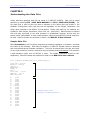
1
INTRACRANIAL SELF-STIMULATION
MED-STATE NOTATION T M PROCEDURE
DOC-128
Rev. 1.1
Copyright © 2008
All Rights Reserved
Med Associates, Inc.
P.O. Box 319
St. Albans, Vermont 05478
www.med-associates.com
MED ASSOCIATES INC.
ICSS PROCEDURES
- ii -
MED ASSOCIATES INC.
ICSS PROCEDURES
TABLE OF CONTENTS
Chapter 1 .............................................................................................. 1
Introduction ...................................................................................................... 1
Overview of the Procedures .............................................................................. 2
Independent Variables ..................................................................................... 3
References ..................................................................................................... 3
Chapter 2 .............................................................................................. 4
Getting Started .................................................................................................. 4
Software Installation ....................................................................................... 4
Backing Up the Software .................................................................................. 4
Chapter 3 .............................................................................................. 5
Beginning & Running an Experiment ..................................................................... 5
Translating The MED-PC IV (.mpc) File............................................................... 5
Using the MED-PC IV Load Wizard ..................................................................... 6
Viewing/Changing Variable Values ..................................................................... 9
Macros ........................................................................................................ 11
Modifying the MedState Notation Code ............................................................. 12
Chapter 4 ............................................................................................ 12
Understanding the MED State Notation TM Procedures............................................. 12
Chapter 5 ............................................................................................ 17
Understanding the Data Files ............................................................................. 17
Sample Data File ........................................................................................... 17
- iii -
MED ASSOCIATES INC.
ICSS PROCEDURES
- iv -
MED ASSOCIATES INC.
ICSS PROCEDURES
CHAPTER 1
Introduction
The purpose of this manual is to give an explanation of the MED State Notation™
Procedures that comprise the SOF-700RA-5 Intracranial Self Stimulation (ICSS)
Procedures. The files in this package can be found on the disk provided by MED
Associates, Inc.
These procedures are intended to be run in MED Associates MED-PC ® IV software. The
latest version of MED-PC ® IV gives researchers the ability to use pre-programmed
procedures such as these to make hardware control and data collection easy. These preprogrammed procedures can also be modified to meet the evolving demands of a
research protocol. Again, it is the intent of this manual to explain exactly what these
procedures implement, and provide guidance into how to interpret what the program
code achieves in order to let the user determine how to modify them to match their
research protocol demands.
The manual provides some examples of editing and
modifying the procedure’s programming code. The manual also defines the elements in
the raw data file produced by these procedures.
In addition to this manual, refer to the MED-PC ® IV User’s Manual for the installation
of the MED-Associates interface drivers, the MED-PC IV Software, and the Delphi ®
Compiler. Also refer to the User’s Manual for instructions on developing a Hardware
Configuration. Data file structure, file-saving format, and other related options are also
determined by the Hardware Configuration.
Running the Hardware Configuration
software utility that accompanies MED-PC IV sets the Hardware Configuration. Its
purpose is to assign the inputs and outputs on the interface cards in the interface cabinet
for each task controlled by MED-PC IV. The particular type of interface card that is
supplied in the interface cabinet may vary; please refer to the User’s Manual provided for
instructions on how to configure the type of card that is in the cabinet. A valid Hardware
Configuration must exist in order for MED-PC IV to interface correctly with the MED
Associates, Inc. hardware. This means that one should take the time to create a valid
Hardware Configuration before attempting to run the procedures included in this
package.
Should there be any problems, the staff at MED Associates, Inc. is available to answer
any questions that may arise. Please e-mail us at [email protected] with a
detailed description of the problem or desired goals so that concise and detailed
information may be provided.
The ICSS procedures are designed to be as easy to use as possible. MED Associates, Inc.
understands that researchers do not have the time to devote to programming and
hardware design, and for that reason, we have undertaken that burden for you. We
sincerely hope that you are satisfied with the products and services we provide, and look
forward to meeting your future experimental needs as your research program evolves.
- 1 -
MED ASSOCIATES INC.
ICSS PROCEDURES
Overview of the Procedures
SOF-700RA-5 is a package of two MEDState Notation TM (MSN) procedures written for the
control of intracranial self-stimulation (ICSS) in threshold determination.
MED Associates, Inc. strongly encourages the creation of a backup copy of the
procedures found on the ICSS CD. Having copies of the original procedures is helpful in
the case of computer failure, and will provide a default copy of the original procedures in
case changes to the programming code are necessary to implement a different
experimental protocol.
Reward.mpc
This procedure uses a Discrete Trial Method developed by Dr. Conan Kornetsky, Boston
University School of Medicine, in which the amplitude of both a free stimulus and a
response contingent stimulus (reward) are the same. It is used while testing a trained
subject.
The program starts off with a free stimulation. If the animal likes the stimulation and
responds, then it receives the same stimulation again as a reward. The program
provides the same stimulation for five trials and then the trial block ends. At the end of
the trial block the program checks how many times the animal responded and received a
reward stimulation.
In Descending trial blocks the program is looking to see how many times the animal did
not respond (i.e. the animal could not feel the stimulation). If the animal does not
respond three out of five times for two consecutive trial blocks, then the program has
found the lower limit and switches to Ascending trial blocks.
In Ascending trial blocks the program is looking to see how many times the animal did
respond to the stimulation (i.e. the animal could feel the stimulation). If the animal does
respond three out of five times for two consecutive trial blocks, then the program has
found the upper limit and switches to Descending trial blocks.
Between trial blocks the program decrements or increments the stimulation amplitude,
depending on the trial type, by the Step Size.
By default the program starts with Descending trial blocks so the User should select a
starting amplitude that is between the expected lower and upper stimulation values. It is
better to guess low than to guess high. For example if the User selects a starting
amplitude that is too high and the animal receives a stimulation that it does not like,
then it will not respond. The program will see that the animal is not responding and
assume that it has found the lower limit and switch to an Ascending trial block. The
problem is that the animal is not responding because he doesn’t like the stimulation, not
because he can’t feel it. The program switching to Ascending trial blocks and increasing
the amplitude will only make the problem worse.
The program will end after four reversals (i.e. A change from a Descending trial block to
a Ascending trial block or a change from a Ascending trial block to a Descending trial
block).
- 2 -
MED ASSOCIATES INC.
ICSS PROCEDURES
Detection.mpc
This procedure is a variation on the reward procedure in which the reward stimulus
remains constant and only the free stimulus changes while testing thresholds. This
procedure is used in training a test subject. It also determines the minimum stimulation
amplitude necessary to produce a response by the test subject.
Independent Variables
Independent
Variable
Description
Range
Default
Value
Step Size
The amount that the current will be
increased or decreased (in uA) during
testing.
-
10 uA
Pulse Width #1
The width of Pulse 1 in microseconds
60 – 32,000 us
200 us
Pulse Amplitude #1
The amplitude of Pulse 1 in microamps
1 – 1,000 uA
80 uA
Pulse Delay
The delay between Pulse 1 and Pulse 2 in
microseconds
60 – 32,000 us
100 us
Pulse Width #2
The width of Pulse 2 in microseconds
60 – 32,000 us
200 us
Pulse Amplitude #2
The amplitude of Pulse 2 in microamps
1 – 1,000 uA
80 uA
Frequency
Frequency in hertz
1 – 2,000 Hz
100 Hz
Pulse Train Duration
Duration of the stimulation in milliseconds
-
500 ms
Pulse Amplitude #2
for S2
This variable used in Detection.mpc
program only. This is the reward stimulus
duration. The value remains constant
during testing. Only Pulse Amplitude #1
and Pulse Amplitude #2 will change during
testing.
-
80 uA
References
Kornetsky, Conan and Bain, George (1990). Brain-Stimulation Reward: A Model for DrugInduced Euphoria, Modern Methods in Pharmacology, Volume 6, Testing and Evaluation
of Drugs of Abuse , Wiley-Liss, Inc., pp. 211-231.
Bird, Michael and Kornetsky, Conan (1990). Dissociation of the Attentional and
Motivational Effects of Pimozide on the Threshold for Rewarding Brain Stimulation,
Neuropsychopharmacology , Volume 3, pp. 33-40.
- 3 -
MED ASSOCIATES INC.
ICSS PROCEDURES
CHAPTER 2
Getting Started
Software Installation
Please refer to the MED-PC IV User’s Manual for a complete guide to installing the
MED-PC IV software, building a valid Hardware configuration with the Hardware
Configuration utility, and opening and compiling a MSN procedure in the Trans-IV utility.
To install the ICSS Procedures, insert the CD into the CD-ROM drive and click Install the
Intracranial Self Stimulation Software. The ICSS procedures are copied into the
C:\MED-PC IV\MPC folder.
Backing Up the Software
Med Associates strongly encourages creating backup copies of the programs in case of
disk failure. Having copies of the original programs may be useful in the future should
modifications be made to the existing programs.
- 4 -
MED ASSOCIATES INC.
ICSS PROCEDURES
CHAPTER 3
Beginning & Running an Experiment
Translating The MED-PC IV (.mpc) File
Programs written in MedState Notation must be translated using Trans IV before they can
be executed in this application. Be sure that a copy of the file being translated is present
in the directory “C:\MED-PC IV\MPC\.” Open Trans IV icon and select Translation |
Translate and Compile.
Select the program(s) to use for the experiment and click Make. Click OK to start the
translator, and it will automatically parse the MedState Notation and then open to a DOS
screen to compile the Pascal code. Depending on the speed of the computer, each of
these steps may not be seen. If any problems are encountered during this process, refer
to the on-screen help menu or the MED-PC Version IV User’s Manual, or contact MED
Associates, Inc. for assistance.
Figure 3.1 - Trans IV Control Panel for Translating and Compiling MedState Notation Code
- 5 -
MED ASSOCIATES INC.
ICSS PROCEDURES
Using the MED-PC IV Load Wizard
MED-PC IV is designed to help the researcher run an experiment by guiding selection
choices through its Experiment Loading Wizard. This section will describe how to initiate
the Detection.mpc application, however the following steps that will also apply to all
other .mpc procedures.
Open MED-PC IV and the MED-PC Experiment Loading Wizard’s Welcome screen, shown
in Figure 3.2 will appear.
Figure 3.2 - The MED-PC IV Loading Wizard Welcome Screen
To avoid this load wizard, deselect the checkbox labeled Run this experiment
automatically when starting MED-PC. Close this screen by clicking the Close button.
Closing this screen immediately reveals the MED-PC Run-Time Screen shown in Figure
3.9. If the choice to continue with the Loading Wizard is made, then click the Next
button.
- 6 -
MED ASSOCIATES INC.
ICSS PROCEDURES
The Box Selection screen will appear next, as shown in Figure 3.3. From this screen the
researcher chooses which boxes will be used in the experiment. Select the boxes that
will run the experiment by clicking in the radio button next to the box number. The
figure shows that the Hardware Configuration included only 1 box, which was selected.
Click Next to continue.
Figure 3.3 - The Box Selection Screen
The Select a Procedure screen appears next, as seen in Figure 3.4. This is where the
application to be run is selected. The screen displays a list of all the currently compiled
procedures. Select the desired procedure and then click Next.
Figure 3.4 - The Select a Procedure Screen
- 7 -
MED ASSOCIATES INC.
ICSS PROCEDURES
The Enter Experiment Data Screen should display next, as shown in Figure 3.5. The
purpose of this screen is to allow annotations to be added to the data file that is
produced by MED-PC IV. These annotations will help identify the Subject, Experiment,
and Experiment Group upon which data was collected. Comments can be added here as
well, and the data file can be given a customized file name to help identify it from other
data files. Enter the information desired, and click Next.
Figure 3.5 - Enter Experiment Data Screen
The next screen to appear is the Review Choices screen, as seen in Figure 3.6. This is a
method of confirming that the information received from the Box/Procedure Selected is
correct. If it is not correct, select Previous, and edit the data. If it is correct, select
Next.
Figure 3.6 - Review Choices Screen
- 6 -
MED ASSOCIATES INC.
ICSS PROCEDURES
The Alter Session Parameters Screen, shown in Figure 3.7, is the next screen to appear,
and is an important screen for the researcher.
The Alter Session Parameters screen
allows the researcher to alter the parameters by which a procedure executes. The Send
Start Command Screen appears next.
The options available on the screen vary
depending upon how many boxes are described in the Hardware Configuration.
Figure 3.7 - Alter Session Parameters Screen
In this example only 1 box is described in the Hardware Configuration, so Figure 3.8 will
appear next. If more than 1 box is in the Hardware Configuration, then Figure 3.9 will
appear.
Figure 3.8 - Send Start Command Screen for Single Box Configuration
- 7 -
MED ASSOCIATES INC.
ICSS PROCEDURES
Figure 3.9 - Send Start Command Screen for Multiple Box Configuration
In both cases (Figure 3.8 and Figure 3.9), the screens are where the researcher decides
to either load more boxes, send a start signal to boxes that are already loaded, or enter
the MED-PC IV run-time environment without sending a start signal by selecting “I am
finished with the wizard”. This option results in the screen shown in Figure 3.10.
Figure 3.10 - The MED-PC IV Run-Time Screen
- 8 -
MED ASSOCIATES INC.
ICSS PROCEDURES
Viewing/Changing Variable Values
Before a “start command” has been issued, any variable may be changed on the MED-PC
IV run-time screen. Simply highlight the value to change, and then enter the new value.
Once a session is in progress, change variables by selecting Configure | Change
Variables, or click the 4th tool bar item ΔX. In the lower left hand corner of the Change
Variables window, find the “Display Data from Box” display, and choose the chamber(s)
to modify. By clicking additional boxes in the “Additional Boxes to Update” section,
changes made to a single box are automatically loaded to all of the selected boxes.
Figure 3.11 - Changing Variables Screen
The value of any simple variable may be viewed from this screen by clicking an array on
the table and each element in that array can be viewed, as shown in Figure 3.12. To
change a value, simply highlight and replace the value in the lower right hand box or use
the up/down arrows to increment by 1. Click the Issue button for the change to take
effect. Click Named Variables to produce the display in Figure 3.13. Change variables
here as needed.
- 9 -
MED ASSOCIATES INC.
ICSS PROCEDURES
Figure 3.12 - Displaying Array A from Box 1
Figure 3.13 - Displaying Named Variables from Box 1
- 10 -
MED ASSOCIATES INC.
ICSS PROCEDURES
Macros
The simplest way to initially create a macro is to record keyboard functions while
performing the steps manually. Once the commands are in the macro, it is easy to
create a number of macros with the macro editor. The following example illustrates the
process of loading “Box 1” and changing the Step Size to 30.
To begin, open MED-PC IV and going directly to the run time screen. Close the load
wizard, if present. Before loading or opening the procedure, click Macro on the main
menu and select Turn On Macro Recorder or click the 8th tool bar item with the
cassette tape icon on top. A note on the bottom of the display indicates that the
recorder is running. Open “Detection.mpc” by clicking Files | Open Session. Change
the variables using any of the methods described above. When all settings have been
made, turn the recorder off again by using the main menu or tool bar. Save the macro
with a distinctive name.
The example in Figure 3.14 was named
“Detection_StepSize_30.mac” since the Step Size was changed to 30.
Figure 3.14 – Detection_StepSize_30.mac
Once this macro is built, use the macro editor to make simple changes such as replacing
reward or correct lever values. Review the Help file on screen or the MED-PC IV User’s
Manual for more information on macros and the features offered. A START command or
message box followed by a START command could be added to the macro (it was left off
here so changes could be verified before starting the procedure).
- 11 -
MED ASSOCIATES INC.
ICSS PROCEDURES
Modifying the MedState Notation Code
Permanent changes to the ICSS procedures can be made to the MedState Notation code.
To make the same change to the Step Size as shown above, do the following. Open
Trans IV and select File | Open to place Detection.mpc into the text editor. Scroll down
to approximately line 97 (note the line counter in the lower right hand corner of the
editor) to reveal the code shown in Figure 3.15.
Figure 3.15 – Detection_StepSize_30.mpc Line 97
On LIST P = change the 10 to a 30 and save the changes with the same or a new file
name such as Detection_StepSize_30.mpc. Remember, if creating a new .mpc file name
and are using a macro to load boxes, the file name in the macro also must be changed.
Translate and compile the new or changed file as described previously and run MED-PC
IV. Use the “Change Variables” screen to view/confirm the new values.
- 12 -
MED ASSOCIATES INC.
ICSS PROCEDURES
CHAPTER 4
Understanding the MED State Notation T M Procedures
The Detection.mpc and Reward.mpc programs are so similar that only the State Sets in the
Detection.mpc program are described in this chapter.
\ Copyright (C) 2008 MED Associates, All rights reserved.
\ Detection.mpc
\
\ Detection Procedure - Discrete Trial Method - Method of Limits
\ Based on procedures for Dr. Conan Kornetsky, Boston Univ., Sch. of Med.
\ Inputs
^Wheel = 1
\
\
\
\
Chambers with Levers will have the LeftLever
connected as Input 1. The constant ^Wheel
may be changed to ^LeftLever here and throughout
the procedure if desired.
\ Outputs
^LeftStimLight
^RightStimLight
^Feeder
^SonAlert
^HouseLight
=
=
=
=
=
1
2
3
4
5
\
\
\
\
The only output used in this
procedure is the HouseLight.
Output constants may be modified
to match individual systems.
\ P() = Control Variables with Assigned Aliases as Defined
Var_Alias Step Size (uA)
= P(0) \ Default = 10uA
Var_Alias Pulse Width #1 (us)
= P(2) \ Default = 200us
Var_Alias Pulse Amplitude #1 (uA)
= P(3) \ Default = 80uA
Var_Alias Pulse Delay (us)
= P(4) \ Default = 100us
Var_Alias Pulse Width #2 (us)
= P(5) \ Default = 200us
Var_Alias Pulse Amplitude #2 (uA)
= P(6) \ Default = 80uA
Var_Alias Frequency (Hz)
= P(7) \ Default = 100Hz
Var_Alias Pulse Train Duration (ms)
= P(8) \ Default = 500ms
Var_Alias Pulse Amplitude #2 for S2 (uA) = P(9) \ Default = 80uA
^Step
^Node
^PWidth1
^PAmp1
^PDelay
^PWidth2
^PAmp2
^Freq
^Dur
^PAmpS2
=
=
=
=
=
=
=
=
=
=
0
1
2
3
4
5
6
7
8
9
\ List Data Variables Here
\ A() = Data Variables Used as Listed
\ A(3) = # of Reversals
\ A(11) = Total Cluster Responses
\ A(12) = Total ITI Responses
\ A(13) = Total Responses
\ A(14) = Total Free Stimuli
\
C() = Master Data Array.
All data transferred to this array for Printing
\ List Working Variables Here
\ A() = Counter Variables Used as Listed
\ A(0) = # of Non-Responses in Descending Column or Responses in
\
Ascending Column in a 5 Trial Block (If A(0) >= 3 Increment A(2))
\ A(1) = # of Reward Stimulations in a 5 Trial Block
\ A(2) = # of Consecutive 5 Trial Blocks in which Criteria is Met
\
(If A(2) = 2, Procedure Changes from Ascending to Descending Trial
\
Block and Vice-Versa)
\ A(4) = Ascending/Descending Trial Block Tag
\
A(4) = 0 if Descending
\
A(4) = 1 if Ascending
\
Program Starts with a Descending Trial Block
\ A(5) = Trial Counter. If A(5) = 5 Record Data and set up for new Series
\ A(6) = ITI Interval
\ A(7) = Cluster Responses
\
(1st. & all Subsequent Responses for First 2" of ITI.)
\ A(8) = ITI Responses
\ A(9) = Tag for Responses made During Free Stimulus. 1 = Response Made
\
0 = No Response Made
\ A(10) = Block Counter. Each Block Contains 5 Trials
\ A(16) = Value of Stim. Current for Data Printout. Gets set to
\
the value of P(3) at Start of Procedure and after data
\
is transferred to the C-Array
\ A(17) = Value of Ascending/Descending trial block tag. Starts at
\
zero by default and gets set to the value of A(4) after
\
data is transferred to the C-Array
- 12 -
MED ASSOCIATES INC.
\
\
\
\
\
\
\
B
D()
J
P()
ICSS PROCEDURES
=
=
=
=
Response Latency counter (Resolution 0.01 sec.)
Response Latencies for each Trial Block (Subscript A(5))
Subscript for the Master Data Array C (i.e., Set C(J) = A(4))
Stimulator Parameters
LOW LIMIT DEFAULT: Set at 10 microamperes in S.S.1, S8.
HIGH LIMIT DEFAULT: Set at 200 microamperes in S.S.1, S13.
T() = List of Available ITI Intervals. Mean 15 seconds.
DIM A = 20
DIM C = 500
DIM D = 10
LIST P = 10, 0, 200, 80, 100, 200, 80, 100, 500, 80
LIST T = 7.5", 9", 10.5", 12", 13.5", 15", 16.5", 18", 19.5", 21", 22.5"
\ Z-Pulses Used in this Program
\ Z1 = Signal Start of a Free Stimulus.
\ Z2 = Signal Start of ITI Period.
\ Z3 = Signal for no Response Made During 7.5" Following Free Stim.
PRINTVARS
= C
PRINTOPTIONS = 80,FORMFEEDS
PRINTFORMAT = 6.2
\***************************************************
\
Detection Schedule
\ S1 - Set Default Values
\
Step Size
(10uA)
\
Pulse Width #1
(200us)
\
Pulse Amplitude #1
(80uA)
\
Pulse Delay
(100us)
\
Pulse Width #2
(200us)
\
Pulse Amplitude #2
(80uA)
\
Frequency
(100Hz)
\
Pulse Train Duration
(500ms)
\
Pulse Amplitude #2 for S2 (80uA)
\***************************************************
State Set 1 is the main portion of the program. It determines if this is an Ascending or Descending
trial, and whether or not the criteria has been met to switch to the other trial type. It also contains
the stimulation values and when to end the program.
States 3 – 5 are used to set up the free stimulation at the beginning of a trial and determine if this is
an Ascending or Descending trial.
S.S.1,
S1, \ Turn HouseLight ON when Procedure "STARTS"
#START: CLEAR 1,60; ON ^HouseLight;
SET P(^Node) = BOX, A(10) = 1, A(16) = P(^PAmp1) ---> S2
1": SHOW 1,Step Size,P(^Step),
2,Pulse Width 1,P(^PWidth1), 3,Pulse Amp 1,P(^PAmp1);
SHOW 4,Pulse Delay,P(^PDelay), 5,Pulse Width 2,P(^PWidth2), 6,Pulse Amp 2,P(^PAmp2);
SHOW 7,Frequency,P(^Freq),
8,Pulse Train Dur,P(^Dur),
9,S2...,P(^PAmpS2);
SHOW 10,Node,BOX ---> SX
S2,
0.1": ~Stimulate(MG, P[1], P[2], P[3], P[4], P[5], P[6], P[7], P[8]);~ ---> S3
S3,
\ Free Stimulation Given at Start of Procedure
0.01": ~StimOn(MG, BOX, 1);~; ADD A(5), A(14); Z1 ---> S4
S4,
\ Pause during Stimulation. Note: Duration of Stimulation
\ is passed with Stimulate command parameter P[8] (P(^Dur)).
\ Reset Stimulator parameters for S2
\ Test for a Response during Free Stimulation.
0.5": ~Stimulate(MG, P[1], P[2], P[9], P[4], P[5], P[9], P[7], P[8]);~;
IF A(9) = 1 [@Response, @NoResponse]
@Resp: ---> S5
@NoResponse: IF A(4) = 0 [@T, @F]
@T: ---> S6
\ Descending Trial
@F: ---> S11 \ Ascending Trial
#R^Wheel: ADD A(7), A(11); SET A(9) = 1 ---> SX
S5,
\ If Response occurs during the Free Stim. Pause 0.5", Deliver
\ a Reward Stimulation and Terminate the Trial.
0.5": ADD A(1); ~StimOn(MG, BOX, 1);~; Z2;
IF A(4) = 0 [@T, @F]
@T: ---> S9
\ Descending Trial
@F: ADD A(0) ---> S14 \ Ascending Trial
- 13 -
MED ASSOCIATES INC.
ICSS PROCEDURES
States 6 – 9 are used to control the Descending Trials.
At the end of each trial State 7 tests the following:
• If the number of trials in the block have been completed (IF A(5) >= 5).
• If the three trials with no response criteria has been met (IF (A(0) >= 3).
• If the two consecutive blocks criteria has been met (IF A(2) >= 2).
• If the four reversal criteria has been met (IF A(3) >= 4).
State 8 tests the following:
If the absolute lower limit for the amplitude has been reached (IF P(^PAmp1) <= 10). If it has,
then an automatic reversal happens.
•
If the four reversal criteria has been met (IF A(3) >= 4).
•
The user may change any of these criteria by changing the appropriate IF statements in States 7 and
8. The same IF statements in States 12 and 13 must also be changed.
Note: The number of trials in a block (IF A(5) >= 5) cannot be changed without also changing how
the data is saved in the C Array.
\---------------------------------------------------------------------------------------------------------------S6,
\ Start of Descending Trial
7.5": ADD A(0); Z2; Z3 ---> S9
#R^Wheel: ADD A(1), A(7), A(11); ~StimOn(MG, BOX, 1);~; Z2 ---> S9
S7,
0.01": IF A(5) >= 5 [@EndTrialBlock, @ContTrialBlock]
@EndTrialBlock: IF A(0) >= 3 [@CriteriaMet, @CriteriaNotMet]
@CriteriaMet: SET A(0) = 0; ADD A(2);
IF A(2) >= 2 [@TwoCriteriaMet, @TwoCriteriaNotMet]
@TwoCriteriaMet: SET A(2) = 0; ADD A(3);
IF A(3) >= 4 [@EndProcedure, @ContinueProcedure]
@End: RANDD A(6) = T ---> S17
@Cont: RANDD A(6) = T; SET A(4) = 1 ---> S16
\ Change to Ascending Trial
@TwoCriteriaNotMet: ---> S8
@CriteriaNotMet: SET A(0) = 0, A(2) = 0 ---> S8
@ContTrialBlock: RANDD A(6) = T ---> S15
\ Add Trial Count, set new ITI Value
S8,
\ Test Lower Limit and Decrease Current
0.01": IF P(^PAmp1) <= 10 [@LowerLimit, @Continue]
@LowerLimit: ADD A(3); IF A(3) >= 4 [@EndProcedure, @ContinueProcedure]
@End: RANDD A(6) = T ---> S17
@Cont: RANDD A(6) = T; SET A(4) = 1 ---> S16
\ Change to Ascending Trial
@Continue: SET P(^PAmp1) = P(^PAmp1) - P(^Step);
SET P(^PAmp2) = P(^PAmp2) - P(^Step);
~Stimulate(MG, P[1], P[2], P[3], P[4], P[5], P[6], P[7], P[8]);~;
RANDD A(6) = T ---> S16
S9,
\ Wait for S2 Pulse Train to End if Delivered
\ Return to S1 parameters
\ Continue Descending Trial
0.5": ~Stimulate(MG, P[1], P[2], P[3], P[4], P[5], P[6], P[7], P[8]);~ ---> S7
- 14 -
MED ASSOCIATES INC.
ICSS PROCEDURES
States 11 – 14 are used to control the Ascending Trials.
At the end of each trial State 12 tests the following:
• If the number of trials in the block have been completed (IF A(5) >= 5).
• If the three trials with no response criteria has been met (IF (A(0) >= 3).
• If the two consecutive blocks criteria has been met (IF A(2) >= 2).
• If the four reversal criteria has been met (IF A(3) >= 4).
State 13 tests the following:
If the absolute lower limit for the amplitude has been reached (IF P(^PAmp1) <= 200).
If it has, then an automatic reversal happens.
• If the four reversal criteria has been met (IF A(3) >= 4).
•
Any of these criteria may be changed by changing the appropriate IF statements in States 12 and 13.
The same IF statements in States 7 and 8 must also be changed.
Note: The number of trials in a block (IF A(5) >= 5) cannot be changed without also changing how
the data is saved in the C Array.
\---------------------------------------------------------------------------------------------------------------S11,
\ Start of Ascending Trial
7.5": Z2; Z3 ---> S14
#R^Wheel: ADD A(0), A(1), A(7), A(11); ~StimOn(MG, BOX, 1);~; Z2 ---> S14
S12,
0.01": IF A(5) >= 5 [@EndTrialBlock, @ContTrialBlock]
@EndTrialBlock: IF A(0) >= 3 [@CriteriaMet, @CriteriaNotMet]
@CriteriaMet: SET A(0) = 0; ADD A(2);
IF A(2) >= 2 [@TwoCriteriaMet, @TwoCriteriaNotMet]
@TwoCriteriaMet: SET A(2) = 0; ADD A(3);
IF A(3) >= 4 [@EndProcedure, @ContinueProcedure]
@End: RANDD A(6) = T ---> S17
@Cont: RANDD A(6) = T; SET A(4) = 0 ---> S16
\ Change to Descending Trial
@TwoCriteriaNotMet: ---> S13
@CriteriaNotMet: SET A(0) = 0, A(2) = 0 ---> S13
@ContTrialBlock: RANDD A(6) = T ---> S15
\ Add Trial Count, set new ITI Value
S13,
\ Test Upper Limit and Increase Current
0.01": IF P(^PAmp1) >= 200 [@UpperLimit, @Continue]
@UpperLimit: ADD A(3); IF A(3) >= 4 [@EndProcedure, @ContinueProcedure]
@End: RANDD A(6) = T ---> S17
@Cont: RANDD A(6) = T; SET A(4) = 0 ---> S16
\ Change to Descending Trial
@Continue: SET P(^PAmp1) = P(^PAmp1) + P(^Step);
SET P(^PAmp2) = P(^PAmp2) + P(^Step);
~Stimulate(MG, P[1], P[2], P[3], P[4], P[5], P[6], P[7], P[8]);~;
RANDD A(6) = T ---> S16
S14,
\ Wait for S2 Pulse Train to End if Delivered
\ Return to S1 parameters
\ Continue Ascending Trial
0.5": ~Stimulate(MG, P[1], P[2], P[3], P[4], P[5], P[6], P[7], P[8]);~ ---> S12
States 15 – 17 are used to time the Inter-Trial Interval and save the data from each trial. Responses
during the ITI are punished by resetting the ITI.
\---------------------------------------------------------------------------------------------------------------S15,
\ ITI Interval for Trials 1-4 of Trial Block.
#R^Wheel: ---> S15
\ Punish Responses in ITI by Resetting Timer
A(6)#T: SET A(9) = 0 ---> S3 \ End ITI Interval
S16,
\ ITI Interval & Data Saving for End of Block of 5 Trials.
#R^Wheel: ---> S16 \ Punish Responses in ITI by Resetting Timer
A(6)#T: SET C(J)
= A(17), C(J+1) = A(16), C(J+2) = A(1), C(J+3) = D(1);
SET C(J+4) = D(2), C(J+5) = D(3), C(J+6) = D(4), C(J+7) = D(5);
SET C(J+8) = A(7), C(J+9) = A(8), A(1) = 0, A(7) = 0, A(8) = 0;
SET J = J + 10;
IF J = 500 [@AbortProcedure, @StartNewTrialBlock]
@Abort: PRINT ---> S20
@StartNew: SET C(J) = -987.987, A(5) = 0;
SET A(16) = P(^PAmp1), A(17) = A(4);
SET A(9) = 0; ADD A(10);
ZEROARRAY D ---> S3
- 15 -
MED ASSOCIATES INC.
ICSS PROCEDURES
S17,
\ Save Data from last Trial Block and Generate Printout
A(6)#T: SET C(J)
= A(4), C(J+1) = A(16);
SET C(J+2) = A(1), C(J+3) = D(1);
SET C(J+4) = D(2), C(J+5) = D(3);
SET C(J+6) = D(4), C(J+7) = D(5);
SET C(J+8) = A(7), C(J+9) = A(8);
SET C(J+10) = -987.987; PRINT ---> S20
S20,
\ End Procedure
1": ---> STOPABORTFLUSH
State Set 2 records the latency to the response during the trial.
\***************************************************
\
RESPONSE LATENCY
\***************************************************
S.S.2, \ Record Response Latency in Array D until End of 5 Trial Block
S1,
\ when transferred to Print Array. See S.S.1, S16 & S17.
#Z1: ---> S2 \ Start "Clock" with Occurance of Free Stimulus
S2,
#R^Wheel: SET D(A(5)) = B, B = 0 ---> S1
#Z3: SET B = 0 ---> S1 \ No Response Made
0.01": SET B = B + 0.01 ---> SX
State Set 3 counts the Cluster Responses and the number of Responses during the ITI. Cluster
Responses is the first response that happens during the trial and all of the responses during the first 2
seconds of the ITI.
\***************************************************
\
COUNT CLUSTER/ITI RESPONSES
\***************************************************
S.S.3, \ Counters transferred to Print Array and Reset at End of
S1,
\ each 5 Trial Block. See S.S.1, S16.
#Z2: ---> S2
S2,
#R^Wheel: ADD A(7), A(11) ---> SX
2": ---> S3
\ Count Cluster Responses
S3,
#R^Wheel: ADD A(8), A(12) ---> SX
#Z1: ---> S1
\ Count ITI Responses
State Set 4 counts the total number of Responses.
\***************************************************
\
COUNT TOTAL RESPONSES
\***************************************************
S.S.4,
S1,
#START: ---> S2
S2,
#R^Wheel: ADD A(13) ---> SX
\ Count Total Responses
State Set 5 updates the display with the most current information for the running trial.
\***************************************************
\
DATA DISPLAY
\***************************************************
S.S.5,
S1,
#START: ---> S2
S2,
0.5": SHOW
SHOW
SHOW
SHOW
1,Column #,A(3)+1,
4,Stim Amplitude,A(16),
12,Cluster Resp,A(7),
15,Two Criteria Met,A(2)
2,D/A Tag,A(4),
5,Reward,A(1),
13,ITI Resp,A(8),
---> S3
3,Block #,A(10);
11,Resp Latency,D(A(5));
14,Criteria Met,A(0);
S3,
0.1": SHOW 21,Total Cluster Resp,A(11), 22,Total ITI Resp,A(12), 23,Total Resp,A(13);
SHOW 24,Total Free Stimuli,A(14), 31,Trial #,A(5),
32,ITI Interval,A(6)/1";
SHOW 33,Resp Dur Free Stim,A(9) ---> S2
- 16 -
MED ASSOCIATES INC.
ICSS PROCEDURES
CHAPTER 5
Understanding the Data Files
Unless otherwise specified, data will be saved to C:\MED-PC IV\DATA. Data can be saved
manually by selecting FILE | SAVE DATA MANUALLY or FILE | SAVE DATA (FLUSH). The
file name that is used to save the data in depends on the option that was chosen in the
Hardware Configuration Utility and may also be dependent on the Subject, Experiment, and
Group name provided in the MED-PC IV load wizard. Within each data file, the headings are
created for each Subject, Experiment, Group, Box, etc., (see below). Data files may be opened
with note pad, word pad, or any word processor or spreadsheet; however, be sure they are
always saved “unformatted” in case a data extraction utility such as MED-PC to Excel might ever
be used. Data file formats are explained in detail in the MED-PC IV User’s Manual.
Sample Data File
Select Annotated on the file options page during hardware installation to produce a raw data
file similar to the following. Data files are located in C:\MED-PC IV\Data\ unless an alternate
path was defined during hardware installation. They may be opened with note pad, word pad,
or any word processor; however, make sure they are always saved unformatted in the occasion
a data extraction utility such as MPC2XL is used. The header information should be selfexplanatory. Data-file formats are explained in detail in the MED-PC IV User’s Manual.
File: C:\MED-PC IV\DATA\!2006-12-06_09h09m.Subject 7
Start Date: 12/06/06
End Date: 12/06/06
Subject: 7
Experiment: 5
Group: 1
Box: 1
Start Time: 9:09:59
End Time: 9:36:59
MSN: Detection
Session identification information that was entered during the load wizard.
B:
E:
F:
G:
H:
I:
J:
K:
L:
M:
N:
O:
Q:
R:
S:
U:
V:
W:
X:
Y:
Z:
B = Response Latency Counter
J = Subscript for the Master Data Array C
0.000
0.000
0.000
0.000
0.000
0.000
130.000
0.000
0.000
0.000
0.000
0.000
0.000
0.000
0.000
0.000
0.000
0.000
0.000
0.000
0.000
- 17 -
MED ASSOCIATES INC.
ICSS PROCEDURES
A:
0:
5:
10:
15:
20:
0.000
5.000
5.000 10500.000
14.000
73.000
0.000
80.000
0.000
0.000
10.000
15.000
1.000
4.000
2.000
88.000
0.000
1.000
0.000
70.000
0.000
C:
Most of these values are used for the
control/flow of the program. At the end
of the program the values that still mean
something are:
A(3): Number of Reversals
A(11): Total Cluster Resp
A(12): Total ITI Resp
A(13): Total Responses
A(14): Total Free Stimuli
The C Array contains the main data that
is saved from the program. Data is
saved in blocks of 10. Here is what the
data means:
0:
5:
0.000
0.000
80.000
2.190
4.000
5.070
5.790
9.000
4.430
4.000
10:
15:
0.000
1.860
70.000
0.000
2.000
2.980
0.000
4.000
0.000
1.000
20:
25:
0.000
0.000
60.000
0.000
0.000
0.000
0.000
0.000
0.000
0.000
30:
35:
1.000
0.000
60.000
7.760
1.000
0.000
0.000
1.000
0.000
0.000
40:
45:
1.000
0.000
70.000
0.000
1.000
0.000
0.000
2.000
1.940
0.000
50:
55:
1.000
7.590
80.000
2.180
4.000
0.000
3.670
15.000
1.070
5.000
60:
65:
1.000
1.060
90.000
2.380
4.000
2.350
1.440
12.000
0.000
0.000
70:
75:
0.000
1.290
90.000
1.540
5.000
1.810
5.790
8.000
1.190
1.000
C(J+4): Response Latency for
2nd Trial
80:
85:
0.000
1.750
80.000
5.860
4.000
0.000
4.420
4.000
4.270
0.000
C(J+5): Response Latency for
3rd Trial
90:
95:
0.000
0.000
70.000
1.140
2.000
0.000
0.000
2.000
2.360
0.000
100:
105:
0.000
0.000
60.000
0.000
0.000
0.000
0.000
0.000
0.000
0.000
110:
115:
1.000
0.000
60.000
0.000
1.000
0.000
0.000
1.000
5.560
0.000
120:
125:
1.000
1.230
70.000
6.410
3.000
0.000
3.190
5.000
0.000
2.000
130:
135:
1.000
3.160
80.000
1.460
5.000
1.240
1.600
10.000
1.390
2.000
0.000
1.240
0.000
1.600
0.000
1.390
0.000
3.160
0.000
1.460
0.000
10.000
200.000
1.000
80.000
200.000
100.000
80.000
500.000
100.000
80.000
D:
0:
5:
10:
P:
0:
5:
- 18 -
C(J): 0 = Descending Trial
Block
1 = Ascending Trial
Block
C(J+1): Stim Amplitude Value
this Trial Block
C(J+2): # Reward Stims this
Trial Block
C(J+3): Response Latency for
1st Trial
C(J+6): Response Latency for
4th Trial
C(J+7): Response Latency for
5th Trial
C(J+8): Number of Cluster
Responses this Trial
Block
C(J+9): Number of ITI Responses
this Trial Block
The D Array is used to save the response
latency for each trial (1 – 5). The values
are saved to the C Array at the end of
each Trial Block.
The P Array contains the starting
stimulation values.
MED ASSOCIATES INC.
ICSS PROCEDURES
T:
0: 7500.000 9000.000 10500.000 12000.000 13500.000
5: 15000.000 16500.000 18000.000 19500.000 21000.000
10: 22500.000
- 19 -
The T Array contains the ITI values that
were used in the program. The values
were converted to MED Ticks once the
program was loaded.