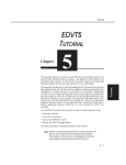
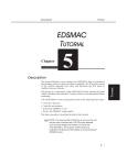
1
3D Viewer
Version 6.0
Software To Draw With, Experience to Draw From
The CAD Zone 4790 SW Watson
Beaverton, OR 97005
Phone: (800) 641-9077
(inside the US) (503) 641-0334
FAX: (503) 641-9077
Copyright© 2002, The CAD Zone, Inc.
All Rights Reserved
Index
2D
Camera Views 3 - 7, 3 - 8, 3 - 10
Diagrams 1 - 3
Icon 3 - 15 (see also, Speedbar)
3D
Attributes 3 - 3
Blocks 4 - 9
Builder 2 - 2, 4 - 5, 4 - 8
Building Tools 3 - 3
Linetypes 4 - 2
Overpass 4 - 10
Settings 2 - 3
Snapshot 3 - 14
Speedbar 2 - 4
Tutorial 3 - 2
View 2 - 2
Viewer 2 - 4
E
S
Elevate Object/Point 2 - 3
3D Linetypes 4 - 3
Body Symbols 4 - 8
Walls 4 - 4
Show 2D View 2 - 5
Snapshot 3 - 15
Button 2 - 4
Manager 2 - 2, 3 - 14
F
Flat view 3 - 14
Flat View Buttons 2 - 4
G
Adding
3D Walls 3 - 3
Windows 4 - 5
Custom Line Types 3 - 6
Additional Help Resources 1 - 4
Apply to Selected Object(s) 2 - 3
Arrow Keys 2 - 7, 3 - 11
Auto Snaps 4 - 3
B
I
Isometric view 3 - 13
Isometric View Buttons 2 - 4
Lamp Post 4 - 9
Line-of-sight 4 - 11
M
Manipulating The 3D View 2 - 5
Mouse Methods 2 - 6
Move (arrow) Keys 3 - 10
Move Buttons 2 - 4
N
Navigating 2 - 6, 3 - 13
With The Numeric Keypad 2 - 7
Background Color 2 - 10
C
Camera 2 - 10, 3 - 7
Elevation 2 - 5
Height 3 - 9
Icon 3 - 14 (see also, Speedbar)
Position 3 - 7
Changing your 3D View 3 - 7
Colors 2 - 10
Compatibility 1 - 3
Creating Buildings 4 - 8
Custom Line Types 3 - 6
D
Diagram Program 1 - 3
Display Roof 4 - 9
Stacking
3D Objects 4 - 2
Rectangles 4 - 8
Ground Plane Color 2 - 10
L
A
Speedbar 3 - 13
Commands 2 - 6
Step Angle 2 - 11, 3 - 10
Step Distance 2 - 11, 3 - 10
System Requirements 1 - 4
T
Taking A Snapshot 2 - 8
Target 3 - 7
Elevation 2 - 5
Symbol 3 - 8
Thumbnails 3 - 14
W
Walking through your drawing 3 - 10
Wall
Height 2 - 2
Paint 2 - 3
Paint box 4 - 4
Numeric keypad 3 - 10 (see also,
Mouse Methods)
Wireframe 2 - 10
Wireframe Drag 2 - 10
Witness POV’s 4 - 11
P
Z
Positioning
the Camera And Target 2 - 5
Zoom Commands 2 - 4, 2 - 6, 3 - 13
Zoom Full 2 - 7
Zoom In 2 - 7
Zoom Out 2 - 7
Zoom Window 2 - 7
Preference values 3 - 10
Preferences Toolbox 2 - 10
R
Render Methods 2 - 10
Return To 2D 2 - 5
Roof 2 - 3 (see also, Display Roof)
Rotate
Buttons 2 - 4
Camera Around Target 2 - 11
Keys 3 - 10
Target Around Camera 2 - 11
Chapter 4 - How Do I?
Chapter 4 How Do I?
“How do I add windows?” “How do I put an object on top of another?” This chapter is for the users who want to draw more complex and detailed 3D diagrams. It goes beyond the viewing capabilities of the program and focuses more on how to draw actual 3D
objects. It has tips and instructions on using the 3D Builder tool in
the 2D program to get the results you want.
In this Chapter
• Stacking 3D Objects
• Custom 3D Linetypes
• Elevating Linetypes
• Elevating Walls
• Adding a Window
• Elevating Body Symbols
• Creating a Lamp Post
• Drawing a 3D Overpass
• Witness Points of View
• Glossary of 3D Terms
4- 1
Chapter 4 - How Do I?
Stacking 3D Objects
Any objects in the program (like symbols, bodies, walls, lines, curves and
circles) can be given 3D values for elevation and height. The height value
determines the height to which the object is extruded in 3D space and the
elevation determines if the object is placed above or below the ground plane.
For example, an object with an elevation of 4' will be placed 4' above the
ground plane. You can use the height and elevation values to make one 3D
object sit on top of another 3D object. This is known as “stacking.”
In the examples below we will show how you can use stacking to get the 3D
results you want. For example, by default a body has an elevation of 0, which
places it on the ground or floor. If you select that same body and use the 3D
Builder toolbox to give it an elevation of 2', the body can now be shown lying
on top of a bed. A section of building can be stacked on top of another section
of building. A skybridge between two buildings is created by extruding the
walls of the bridge and elevating the entire bridge to the required height. To
create an archway or bridge, use the elevation values to stack one block on
top of two supporting blocks. Stacking is even used to create windows by
stacking an opening, or hole, on top of a section of wall, then elevating
another section of wall on top of the opening.
Using 3D Linetypes
Many custom line types in the Diagram Program convert automatically in the
3D Viewer to 3D objects. The illustration below shows some of the line types
that convert to 3D entities. Other custom line types will be displayed in the
3D Viewer just as they are in 2D. For example, footprints and skidmarks will
still be displayed as flat, 2D objects.
Some of the custom line types that convert to 3D objects are:
• cyclone fence (10' tall) • concrete wall (4' tall) • barbed-wire fence (4' tall)
• power poles
• guardrails
• highway dividers
• cones
• barrels
• concertina (razor) wire
• car1 line type
• car2 line type
• motorcycle line type.
4- 2
Figure 4.1 - Custom Linetypes that convert to 3D
Chapter 4 - How Do I?
Elevating 3D Linetypes
In certain cases you may wish to elevate a custom line type. For example you
might want to raise the concertina wire line type so it sits on top of the
cyclone fence. The cyclone fence is 10' tall, so the concertina wire should be
raised to an elevation of 10'. This is another example of stacking one object
on top of another.
To create a fence with concertina wire on top:
Draw a line on the screen using the cyclone fence line type.
Select the concertina wire line type from the line types menu.
Draw the concertina wire line directly on top of the cyclone
fence line.
Make sure to use your
Auto Snaps command to
snap to the endpoints of
the first line so the
concertina line is drawn
exactly over the existing
cyclone fence line.
Select the
concertina line by
clicking on it with
your mouse.
Figure 4.2 - Elevating 3D linetypes.
It may be difficult to select an object that’s directly on top of another object.
You may want to drag a crossing selection window (drag the window right to
left) to select both lines and then de-select the cyclone fence by holding down
the shift key and clicking on it. Another method is to actually move one line
off the other, elevate the concertina wire, then move the two lines to be back
on top of each other.
Once the concertina
wire is selected, click
on the 3D Builder
toolbox and set the
Elevation to 10'. The
height should be 0'.
Press the “Apply to
Selected Object(s)”
button.
Switch to the 3D Viewer to see
that the concertina wire is positioned on top of the cyclone fence.
4- 3
Chapter 4 - How Do I?
Elevating Walls
You use the 3D Builder toolbox to elevate the interior walls of your crime
scene. This figure shows the 2D view and 3D view without elevated walls.
Figure 4.3 - 2D and 3D views without 3D walls.
To elevate walls in your diagram:
3D Builder
Toolbox
Select all of the walls in the diagram by holding down the Shift
key and clicking on each of the wall segments with your
mouse pointer.
Select the 3D Builder icon from the speedbar.
When the 3D Builder toolbox appears on the screen click
inside the wall height field and set the wall height to 8’0"
If you don’t want the walls to be transparent, check the Wall Paint box and
select a wall color. The wall paint color defaults to a teal green color. If
another wall color is
desired, simply click the
down arrow to display the
drop down color menu.
Choose a different color
from the menu by
clicking on it.
3D Viewer Icon
4- 4
Click the Apply to
Selected Object(s)
button to finish
the command.
Switch to the 3D
Viewer to see the
result.
Figure 4.4 - The result of adding 3D walls
Chapter 4 - How Do I?
Adding a Window
3D windows are best constructed as blank openings, or holes, in your 3D
walls that allow you to “see” through them. It is especially important to learn
how to create 3D windows to give your 3D diagrams a more realistic look. In
this example we will create a window by adding a wall height to two line
segments and stacking them to create the window opening.
Draw a line by using Auto Snaps to snap between points A
and B.
Click on the line you just drew to select it and move it away
from the wall. (This will make it easier to apply 3D values to it
later.)
Repeat this process to draw a second line between points A
and B.
These two lines make up the wall segments below and above the window.
The blank space between the wall sections will act as the window. First we’ll
create the 3' tall lower portion of the wall below the window opening:
Click on the first line segment to select it, and open up the 3D
Builder toolbox. Apply a wall height of 3' to it and an elevation
of 0'.
Next we will create the 1' top portion of the wall and elevate it 4' above the
Figure 4.5 Adding a Window
first wall section for a total elevation of 7':
Click on the second line segment (the one you moved) to
select it, and open up the 3D Builder again. Apply a wall
height of 1' and an elevation of 7'.
4- 5
Chapter 4 - How Do I?
This creates a 3' section of wall, a 4' opening for the window, then another 1'
section of wall for a total wall height of 8' .
Next, we’ll move the upper wall segment back between points A and B.
Again, we’ll assume Auto Snaps is turned on so you can snap the line exactly
to the points.
Click on the second line segment (the one with the 1' height)
to select it.
Select the Move command from the Edit pull-down menu. This
command lets you move a selected object by selecting a
reference point and snapping it exactly to some other point.
For the reference point, snap to the endpoint of the line at
point A.
Snap to point B on the wall to move the line segment back to
it’s original position.
Figure 4.6 - Finishing the placement of the window symbol
4- 6
Chapter 4 - How Do I?
Figure 4.7 shows the resulting window opening as it appears
in the 3D Viewer.
Change the view so you can see the tree through the window.
Figure 4.7 - The window opening as it appears in the 3D Viewer.
Figure 4.8 shows an example of walls which have been constructed using two
lines spaced 6" apart. Each section of wall must be a completely enclosed
rectangle. The windows were made with the same process described above,
except that you use a rectangle for each section of wall instead of a single
line. Then one rectangle is given an elevation value that places it above the
window opening.
Figure 4.8 - Drawing double-line 3D walls.
4- 7
Chapter 4 - How Do I?
Elevating Body Symbols
Normally a full view body symbol has a 3D elevation of 0', meaning it is
lying directly on the ground or floor. Using the 3D builder toolbox we can
elevate a body 2' so it appears to be lying on top of the bed.
In the 2D diagram program, place a bed symbol and then use
the Body command (on the right-hand toolbox) to place a
body symbol on top the bed.
Draw a selection window around the entire body symbol to
select it (but do not select the bed) and click on the 3D Builder
toolbox icon.
Click in the Elevate Object field and enter a value of 2'.
Click the “Apply to Selected Object” button.
Launch the 3D Viewer to see the view of the body lying on top
the bed.
Figure 4.9 - Elevating the body symbol
Use Stacking to Create Buildings
Now that you have learned how to use an elevation value to stack objects, the
next examples will not give all of the step by step instructions. Instead, we
will provide easy tips and hints on how to create a variety of 3D objects.
The building in Figure 4.10 was created by stacking rectangles. Using the 3D
Builder toolbox, each rectangle was given a different wall height, elevation,
4- 8
Chapter 4 - How Do I?
and wall color, as shown in the chart. The Display Roof feature was also
checked for each rectangle. The resulting combination of 3D blocks are
combined to form a realistic 3D building in the 3D Viewer.
Figure 4.10 - Drawing a 3D building.
In Figure 4.11 we have added a second building with an attached skybridge.
The skybridge is simply drawn in 2D as a rectangle and snapped to each
building. Then you assign a wall height and elevation to the rectangle to
elevate it off the ground.
Figure 4.11 - Drawing a 3D skybridge.
Creating a Lamp Post
Figure 4.12 shows a 2D drawing of a lamp post that was created from circles
of varying diameters. Each circle is given a wall height (to form a cylinder)
and elevation (to stack them) to form a realistic lamp post in the 3D view. By
giving the circles different heights and elevations we give the 3D post a
telescopic look. The chart shows the 3D Builder settings used to create the
3D lamp post.
4- 9
Chapter 4 - How Do I?
Figure 4.12 - Creating a 3D lamp post.
Drawing a 3D Overpass
An overpass can quickly be generated by elevating a piece of road to a higher
position. Vehicles can also be elevated to the same height so they sit on top of
the elevated road. In Figure 4.13 there are two supports holding up an
elevated road section. Each support is simply drawn as a 2D rectangle and
assigned height values. The road section is then given an elevation value that
is equal to the height of the supports so the road sits on top of the supports.
Figure 4.13 - Creating a 3D Overpass
4- 10
Chapter 4 - How Do I?
Witness POV’s (Point-of-Views)
A powerful way to use the 3D Viewer is to show the point of view of a
person who witnessed a crime or crash. This is useful to prove or disprove
that a witness could indeed see what they claim to have seen. It’s better to use
your 3D Viewer to determine if a witness is not telling the truth about what
they saw, instead of learning about it in the courtroom.
Figure 4.14 shows the point-of-view of three different witnesses to a crime.
Using different camera elevations and drawing line-of-sight lines, we can
generate 3D snapshots of what each witness could see from their vantage
point.
Figure 4.14 - The Witness P.O.V 3D diagram.
In example 4.14 , all three witnesses heard multiple gunshots near the vicinity
of a moving van on their street. Witness 1 was standing in a second story
bedroom of her house looking out the window. Witness 2 was sitting in his
parked car (on the street) getting ready to go to work. Witness 3 was stepping
4- 11
Chapter 4 - How Do I?
out the front door of her house to get the morning paper. After the gun shots
there was a body lying in front of the moving van and a small car speeding
away.
The 2D diagram and 3D views have already been constructed. We simply
need to adjust the camera and target locations to obtain the desired POV for
each witness. You can drag the camera and target symbols to the desired
position in the 2D Camera View window, as we discussed previously in
Chapter 3. For this example, drag the green target symbol to be on the victim
and set the target elevation to 2' (at the right side of the speedbar). The target
will remain in the same position for each witness.
Camera Elevation
Target Elevation
Witness 1 POV
Next, drag the camera symbol to the location of Witness 1 to set up a
snapshot that shows her POV. Witness 1 was standing at the second floor
window of her house. Her eye level is about 13' (8' high first floor + 5' eye
level). Set the camera elevation (at the right side of the speedbar) to 13'. The
resulting view shows that her line-of-sight was probably obstructed by trees
so she was not able to see the scene clearly. Click the Camera icon to take a
snapshot of this witness’ POV.
If you find it hard to fine tune the location of the camera (if it jumps around),
move it as close as you can to the correct location then use your arrow keys to
adjust to the final position. You may want to reduce your Step Distance to 1’
or less in the Preferences toolbox.
4- 12
Chapter 4 - How Do I?
Witness 2 POV
Witness 2 was sitting in the driver’s seat of his car. To get his POV drag the
camera symbol to the witness and set the camera elevation to 3' (eye level
while sitting). The target elevation and position remain the same. From this
view you can see that this witness was unable to see the victim clearly
because of the truck in front of him. Click the camera icon to take another
snapshot.
Witness 3 POV
Witness 3 was standing on her front walkway. To simulate her POV, drag the
camera symbol to her position and set the camera elevation to 5'. The target
position remains the same. From this viewpoint you can see that this witness
probably had the best view of the event.
4- 13
Chapter 4 - How Do I?
Glossary
3D coordinates - The mode of measurement used to specify the length,
width, and height of objects created by 3D modeling.
3D modeling - A CADD capability that allows you to draw objects in three
dimensions, having length, width, and height.
3D Viewer - The CAD Zone’s program which automatically generates a 3D
image from a 2D diagram. The 3D Viewer allows the user to view the scene
from any point and perspective and create a walk-through of the scene.
CAD ( or CADD ) - Acronym for Computer-Aided Design and Drafting.
Default - A predefined value, or parameter, or situation that is assumed by
the program unless you specifically select an alternative.
Elevation - A 2D type of view that is usually taken horizontally looking at
the vertical face of the scene. An example would be the overhead view of a
floor plan and the elevated view of each of the walls that surround it.
Isometric - A view of an object tilted at 30 degrees on both sides.
Oblique View - A view of an object drawn by taking parallel projections
from an elevation.
Perspective - A view of an object showing true angles as they would appear
from a specific point. This usually simulates how the drawing would look to
the human eye.
Plan View - A 2D view of your diagram that is taken from above looking
down, with no perspective aspect. Plan views are commonly used to show the
inside of a building, with the view taken from the ceiling straight down.
Pointing Device - a hardware device such as a mouse or trackball that is used
to control the movement of the mouse pointer and to select points on the
screen.
Prompt - a message displayed by the program informing you what to do
next, such as pick a point or enter information.
Rendering - displays your diagram in 3D by filling individual surfaces with
color.
Selection Box - A rectangle displayed on the screen which is used to select
entities for editing, display, saving and so on. A selection box is defined by
selecting an upper and opposite lower corner point. Any entities completely
within the area or box are selected.
Snap - A common command used to select and connect endpoints of an
object (like two walls) together at a common point.
Snapshot - An image created in the 3D Viewer that is saved as .jpg file.
Snapshot images can also be placed as an image in your 2D diagrams.
View - The portion and aspect of the diagram that is displayed on the screen
based on the actual viewpoint, the type of view selected, and the type of
drawing selected.
Wireframe - a rendering that shows all of the lines used to represent the
image of the design, including those that would not be visible from the actual
viewpoint. Selecting a wireframe view allows you to see through what would
normally be a solid surface.
4- 14
Chapter 4 - How Do I?
Zooms - Commands used to change the portion of the drawing displayed on
the screen from the entire drawing to a small, close-up, detail view. While
view commands change the size at which objects are displayed on the screen,
they do not change the actual size or location of any object in the drawing.
(Also called View Commands.)
4- 15
Chapter 3. - The 3D Tutorial!
Chapter 3 The 3D Viewer Tutorial!
This chapter shows you how to use the 3D Builder and other tools in
The CAD Zone 2D diagram program to create a 3D model of a
scene. You will learn how to extrude 3D objects from simple 2D
shapes and how to use symbols and line types to complete a 3D
scene. Once in the 3D Viewer, you will learn how to manipulate
your 3D model to view it from any position.
In this Chapter
• Adding 3D Walls
• Custom Linetypes
• Changing 3D Views
• Walking through your
drawing
• The Zoom Commands
• Taking A 3D Snapshot
3- 1
Let’s Get Started!
Chapter 3 - The 3D Tutorial!
This tutorial applies to the 3D Viewer and its functions; no lessons on
drawing the initial 2D diagram are taught here. It is assumed that you have
already learned basic drawing skills in your diagram program. Please refer to
the User’s Manual for the particular diagram program that you are using for
more information on how to create a 2D diagram.
In this tutorial, you will be practicing your 3D techniques on a sample
drawing called “Get Going 3D” which was copied to your hard disk when
you installed your program. Figure 3.1 shows the Get Going 3D sample file
that we will be using.
Start The Diagram Program and load the Get Going 3D Tutorial drawing as
follows:
Once the program loads, the “Let’s Get Started” dialog box
appears on the drawing screen.
Click the “Open Existing Drawing” button.
Scroll through the diagrams listed in the “open a diagram”
window.
Scroll down and click on the name to select the file called:
Get Going 3D.CZD
Click the OK button to open the drawing.
You should then see the 2D diagram in Figure 3.1 load on the screen.
Figure 3.1 - The “Get Going 3D” Diagram
3- 2
Chapter 3 - The 3D Tutorial!
Adding 3D Walls
Drawings created in the 2D Diagram Program contain many objects that convert to 3D automatically, like line types and symbols. There are some objects
however, that must have 3D attributes manually assigned to them in order for
them to show up in the 3D Viewer.
You can apply 3D height and elevation values to any entities in your 2D drawing to create buildings, tanks, stacks, sky bridges, room interiors, and almost
anything you can imagine. To do this you use the “3D Builder” tool. The 3D
Builder also has settings for selecting wall and roof paint color.
Now we will add 3D attributes to the walls in the diagram using the 3D building
tools.
Select a wall in the diagram by clicking on it with your mouse
as shown in Figure 3.2.
Figure 3.2 - Selecting the wall
3D Builder Icon.
3- 3
Select the 3D Builder icon from the speedbar.
When the 3D Builder toolbox appears on the screen enter a
wall height of 8'.
Chapter 3 - The 3D Tutorial!
Let’s apply color to our wall by checkmarking the Wall Paint option.
The wall paint color defaults to a teal green color. If another wall color is desired, simply click the down arrow to display the drop down color menu. Choose
a different color from the menu by clicking on it.
Click the Apply to Selected Object(s) button to finish the
command.
Now let’s switch to the 3D Viewer and look at the wall we just modified.
Click the 3D Viewer icon on the speedbar.
3D View Icon.
It takes a moment for the program to automatically build the 3D drawing, so a
progress bar appears. The more 3D objects that you have in your diagram the
longer this process may take.
When the 3D Viewer launches, our drawing is automatically opened. Notice
the vertical wall, which is the result of the 3D height value we applied to it.
Now, let’s return to the 2D Diagram Program and continue to add additional
height and elevation info to objects in the 2D drawing.
Figure 3.3 - Viewing the wall in 3D
3- 4
Chapter 3 - The 3D Tutorial!
You make changes to the diagram by simply returning to the 2D program. Viewing your diagram in the 3D Viewer makes no changes to the actual 2D drawing
so it will be exactly the same as before. Here you modify the diagram to get the
3D results you want by adding height and elevation values to other objects, then
switch to the 3D Viewer again to see the changes. This process can be repeated
as many times as you like, working back and forth between the 2D program and
the 3D Viewer until your diagram is perfect.
Now we’ll finish building the additional 3D walls by following these steps:
Click on one wall, hold down the Shift key on the keyboard
and click on the remaining wall sections to select all of them
together.
Click on the 3D Builder icon and enter a height of 8' for the
walls.
Select the desired wall paint.
Click “Apply to Selected Objects” to apply the 3D data to all
the walls.
You can select multiple objects by holding down the Shift key as you click on
them. Refer to the Electronic Help and the User’s Manual for tips on using the
selection commands. When you select multiple objects and add 3D data to them,
those objects are automatically grouped together. Do not use the Ungroup command on the Edit menu to ungroup these objects, or their 3D data will be lost.
Figure 3.4 show the result of building the 3D walls in the 3D Viewer.
Figure 3.4 - Viewing the 3D walls
3- 5
Chapter 3 - The 3D Tutorial!
Adding Custom Line Types
Many of the custom line types convert in the 3D Viewer to look like the 3D
objects they represent. Some of the custom line types that convert to 3D objects
are:
• cyclone fences (10’ tall) • concrete wall (4’ tall) • barbed-wire fence (4’ tall)
• guardrails
• highway dividers
• power poles
• traffic barrels
• concertina (razor) wire
• traffic cones
• car2 line type
• motorcycle line type
• car1 line type
Other custom line types will be displayed in the 3D Viewer as flat objects, like
they are in 2D. For example, footprints, skidmarks, and railroad tracks are displayed as flat 2D objects, even in the 3D Viewer.
Next let’s go back to 2D mode and add a 3D fence to the diagram.
2D View Icon.
Click the 2D icon from the 3D Viewer Speedbar to return to the
2D Diagram Program.
Click on the Line Types button on the right-hand menu.
Select the Fence 10' line type icon.
Select the Single Line command from the left-hand Draw
menu tool bin.
Place your mouse pointer in the drawing near point “A” as
shown in Figure 3.5.
Figure 3.5 - Drawing the fence
Click your left-mouse button once to start drawing the fence,
drag the mouse over to point “B” as shown in the figure.
3- 6
Chapter 3 - The 3D Tutorial!
Click your left-mouse button a second time to finish placing
the fence line type.
Now Click the 3D Viewer icon to see the fence in the 3D Viewer.
Figure 3.6 - Viewing the fence in 3D
Changing your 3D View
Now we will experiment with the 3D navigation tools that allow you to move
through the 3D diagram and view the scene from different angles. We’ll start by
setting the Camera and Target heights and locations.
The Camera and
Target tools.
When you open a drawing in the 3D
Viewer you can select a camera position
(the view from where you are standing)
and a target position (the point at which
you are looking). You can also define an
elevation for both the camera and the target. Depending on how you set these elevations, you can view the scene at eye
level, as a witness might have seen it, or
from above or even from below the scene.
You change the location of the target and
camera by dragging their symbols in a
“2D Camera View” window. Whenever The 2D Camera View window
one of these targets is moved the 3D
model is redrawn to show the new view as it relates to the repositioned target
and camera.
The target symbol represents the point at which you are looking, or the focus of
the scene. To change the position of the target:
3- 7
Chapter 3 - The 3D Tutorial!
Move your mouse pointer inside the 2D Camera View box that
is initially in the upper-left corner of the 3D screen.
Position your mouse pointer over the top of the red target
symbol.
Click and hold down the left-mouse button, then drag the
target symbol to a new location.
Notice that as you move the target symbol the 3D view is automatically updated to be focused on the new point. Using the same method you can move the
camera symbol around to see how it affects your view of the scene.
Drag the Camera and Target Icons to a
new location...
the diagram view dynamically changes.
The elevation of the camera and target can be set by changing their respective
values on the speedbar at the upper-right of the screen. For example, to look
straight ahead (level) from eye level you might set the camera elevation to 5
feet and the target elevation to 5 feet. If you were looking down towards the
3- 8
Chapter 3 - The 3D Tutorial!
ground at a body you might set the target to an elevation of 1 foot and the
camera elevation to 5 feet.
To simulate a view from a helicopter looking down to the ground you could set
the target elevation to 1' and the camera elevation to 400 ft. If you were looking
up at a cat in a tree you might set the camera elevation to 5 ft and the target
elevation to 25 ft.
Let’s adjust the camera height:
Position your mouse pointer inside the camera elevation field
on the speedbar and click your left mouse button.
Type in a new elevation value of 5' and move your mouse
pointer back onto the viewing screen.
The 3D view is updated to reflect the new camera elevation of 5'. Using this
same method you can also experiment with changing the Target elevation to
see how it affects the 3D view.
Figure 3.7 - The updated Camera Elevation View
You can also change the camera and target elevations by clicking the up or
down “slider arrows” on the speedbar. By default, clicking these arrows adjusts
the elevation value in 10' steps. This stepping increment can be changed in the
Preferences toolbox.
3- 9
Chapter 3 - The 3D Tutorial!
Walking through your drawing
You can navigate through your 3D view using the Move (arrow) keys and Rotate keys located on the speedbar, or you can use a special keyboard method
using the arrow keys on your keyboard’s numeric keypad, if you have one.
(Note, many laptop computers do not have a numeric keypad.) The arrow keys
(up, down, left, right) move you towards and perpendicular to the target. The
(+) and (-) keys rotate the view. If you want to use the numeric keypad, be sure
that the Num Lock function on your keyboard is turned off.
First, let’s adjust the elevation and preference values for a walk-through:
The Camera and
Target tools.
Preferences Icon
At the upper-right of the Speedbar, set
the camera and target elevation to 5ft
high, which is about eye level.
Select the Preferences icon at the
upper-right of the speedbar to open
the Preferences toolbox.
Click in the Step Distance field and
change the value to 1'.
Click in the “Step Angle” field and
change the value to 3 degrees.
Under the Camera/Target heading
click on “Rotate Target around
Camera.”
Click OK to apply the new preference
settings and close the Preferences
dialog box.
Preference Settings
If the Step Distance is too big you may find yourself jumping through walls and
out of position as you click the arrow keys. Larger Step Distances are great for
walking through large plants, cities, and other larger settings. For moving around
in even smaller spaces, for example inside a car, you might want to set your
Step Distance and Angle to 1 inch and 1 degree.
The “Rotate Target around Camera” method moves you through the drawing
in a manner simulating the Viewer turning their body (head and eyes) around
the view. The other option, “Rotate Camera around Target,” gives a “lazy Susan” effect. This effect is ideal for looking at the entire drawing from a high
elevation.
Using the method discussed previously, adjust the target point and the initial
camera position using the 2D Camera View.
Drag the green target symbol to the point where you want to
look, on top of the entertainment center, in this case.
Drag the red camera symbol near the chair in the living room.
3- 10
Chapter 3 - The 3D Tutorial!
This is the point where you imagine yourself initially
standing.
Figure 3.8 - The initial view of the walk-through
From this view you can see the coffee table, the door to the bathroom, and a
portion of the entertainment center. The rest of the entertainment center is hidden by the bedroom wall. Now let’s walk through your diagram using the keyboard arrow keys:
Press the Up arrow key on the numeric keypad.
The “Up”
Arrow key
Moving with the
Arrow keys
This moves the camera and target symbols 1’ in the direction of the target. If
you imagine a line between the camera and target symbols, the Up and Down
arrow keys step the camera along that line, either towards or away from the
target. The Left and Right arrow keys step the camera in a direction that is
perpendicular to this imaginary line. The distance and angle between the camera and the target always remains constant.
Press the Up arrow several times to simulate taking several
steps forward toward the entertainment center.
If you were to continue moving in this fashion, you would probably “run into”
the bedroom wall. You can continue pressing the Up arrow and walk right
through it, or use the left arrow key to move in a perpendicular direction.
Use a combination of the Up and Left arrow keys to move
along the wall until the camera symbol is in the center of the
opening so you can see the entire entertainment center as
shown in Figure 3-9.
3- 11
Chapter 3 - The 3D Tutorial!
Figure 3.10 - The view after walking forward.
Another way to change the direction you are “walking” is to rotate your view
with the + and - keys on the numeric keypad. Press the + key to rotate the target
3 degrees counter-clockwise (the rotation stepping value we set in the preferences toolbox). Rotating the target is like moving your head and changing your
view.
Press the + key on the numeric keypad to rotate the view
counter-clockwise until you can see the bed.
rotating with the
Arrow keys
Figure 3.11 - The resulting view after rotating.
You may need to press the + key 15 or more times to do this, or you can go to
the Preferences dialog box and change the Step Angle to a larger increment.
Once you have turned in the direction you want to look, you can continue to use
the up arrow keys to move toward the target in 1' increments.
3- 12
Chapter 3 - The 3D Tutorial!
You can also navigate around the scene by placing your mouse pointer in the
scene and dragging the mouse up, down, left, or right. Dragging the mouse
upward toward the top of the screen is the same as increasing the elevation of
the camera, as if you are moving up away from the scene.
Place your mouse pointer near the center of the screen and
hold down your left-mouse button.
Slowly drag the mouse upward and notice the view update.
Notice the value for the camera elevation at the upper-right of
the screen has increased.
Dragging the mouse left or right rotates the view of the scene according to the
options that are set in the Preferences dialog.
Slowly drag the mouse to the right, then to the left and notice
the view update.
In this case we set the rotation method to rotate the target around the camera
and use a rotation increment of 3 degrees. You can change these options and
drag the mouse left or right again to see the effect on the view.
Try these different techniques to move around your drawing for awhile to experiment with obtaining a specific view. Remember that you get the best views
if you don’t get too close to objects in the drawing. Viewing the diagram from
further back allows you to better see the relationship of different elements at the
scene.
Using the Speedbar View and Zoom Commands
The 3D Viewer has a variety of commands that allow you to quickly display an
isometric view, display a flat 2D view, and zoom to a specific 3D View. Isometric views of a scene tend to represent the objects as they appear to the eye.
The surface features (such as walls) are drawn at equal angles from horizontal,
with the Z-axis being vertical and the X and Y-axes being at 30 degrees from
horizontal.
Select one of the isometric view icons from the speedbar.
The resulting view is displayed.
You can think of the flat views as displaying the scene from inside a glass cube.
Looking at each side of the cube gives you a different 2D view of the scene.
3- 13
Chapter 3 - The 3D Tutorial!
Select one of the flat view icons from the speedbar.
The resulting 2D view is displayed.
Experiment with the different view commands on your own. They may help
provide somewhat of a shortcut to obtaining a desired view. Sometimes when
using the mouse and numeric keypad navigation tools you may find it frustrating to get exactly the view you want. Selecting one of the flat view or isometric
view commands may help you get the desired view.
There are also Zoom commands on the speedbar which can be used to change
how the scene is displayed on the screen, just as they are used in the 2D program. While zoom commands change the relative size of objects as they are
displayed on the screen, they do not change the actual size or location of any
object in the drawing. Refer to Chapter 2 for a complete description of each of
the Zoom commands.
Keep in mind that a zoomed view is somewhat cropped so it may not be as
realistic of a display. In general, it is better to move around the drawing with the
navigation tools than to zoom, unless you just want to see more detail.
Taking a 3D Snapshot
You use the Snapshot command to take a “photo” of the current view in a .jpg
image format. These snapshots are automatically numbered and saved as jpg
files in a Snapshots folder on your hard disk.
The Snapshot Manager toolbox (found in the 2D diagram program) displays
thumbnails of all the snapshots you take in the 3D Viewer. From there any
snapshot can be viewed and placed back into the 2D drawing. Because the snapshots are jpg images they can easily be inserted into reports, Power Point presentations, or included as an attachment in an email.
In the 3D Viewer take snapshots of some views, as follows:
The Snapshot Icon
Use the various navigation commands to change the view of
the scene to one that you wish to save as a snapshot.
Click the Camera icon on the speedbar.
Change to a different view and click the Camera icon again to
take another snapshot. Repeat this to take as many snapshots
as you wish.
A snapshot of the current view will be saved to the Snapshots sub-folder of the
general program folder. The snapshot files are given the name of the 2D diagram with an underscore and then a sequential number, as follows:
3- 14
Chapter 3 - The 3D Tutorial!
get going 3D_0001.jpg
get going 3D_0002.jpg get going 3D_0003.jpg
To view your snapshots you can return to the 2D diagram program and use the
Snapshot Manager there:
Click the 2D icon on the speedbar.
Upon returning to the 2D program, click the camera icon on
the speedbar to open the Snapshot Manager toolbox.
The Snapshot
Manager Icon in the
Diagram Program
All 3D snapshots that you have taken
of the current diagram are displayed as
thumbnail icons below the preview
window.
Click on any snapshot to
see a larger view of that
image in the preview
window.
You can place the image shown in the
preview window back into the current
drawing:
Previewing snapshots in
the Snapshot Manager
Click the Place button.
Move your mouse pointer onto the diagram, positioning it
where you want to place the image.
Click your left-mouse button to finish placing the snapshot in
the diagram.
Figure 3.12 - Placing the snapshot in the diagram.
3- 15
Chapter 3 - The 3D Tutorial!
Snapshots are automatically scaled to 1/8 the overall size of the drawing on the
screen. Once placed in the drawing, the snapshots can be selected in the diagram and then moved and re-sized.
The Show all option
on the Snapshot
Manager
The Show All box on the Snapshot Manager allows you to see all snapshots
currently in the Snapshots folder. These would include snapshots of the current
drawing as well as any snapshots taken of other drawings. You can select any
snapshot and click the Remove button to completely delete that image from
your hard disk. You can select multiple snapshots to delete by using the Shift
and Control key selection methods.
Click on the Close button when you are ready to exit the
Snapshots dialog.
That completes the 3D Tutorial. You now know how to create 3D objects,
such as walls, elevate objects in 3D space, navigate around your 3D scene,
and take snapshots so you can save any 3D view. In the next chapter we will
demonstrate some more complex 3D concepts such as how to create windows, skybridges, and overpasses, and show a point-of-view.
3- 16
Chapter 2 - The Quick Tour!
Chapter 2 The Quick Tour!
This chapter familiarizes you with the fundamental tools and concepts that are used in The 3D Viewer. It offers you a “quick tour” of
the program screen and commands designed to help you learn the
program quickly and easily.
In this Chapter
• Starting in 2D
• The 3D Viewer
• 3D Viewer Speedbar
• Manipulating 3D Views
• The Zoom Commands
• Navigation Methods
• Taking A Snapshot
• Program Preferences
2- 1
Chapter 2 - The Quick Tour!
On the following pages you will find a “quick tour” of The 3D Viewer. This
tour is intended to get you familiar with the basic tools and concepts you need
to understand in order to use the program efficiently. When finished with this
chapter, move on to Chapter 3 to see how to apply these commands to create
an actual 3D model from a 2D diagram.
It All Starts In 2D
As mentioned above, the 3D Viewer runs side-by-side with the 2D Diagram
Program – either The Crime Zone, The Crash Zone, The Fire Zone, or The
Insurance Zone. Let’s first look at the tools that you will use in the 2D
Diagram Program prior to launching the 3D Viewer.
3D View - Clicking this button takes you from the 2D program into the
3D Viewer. The 2D program is not shut down, but remains active with the
2D plan view drawing still open. From the 3D Viewer, simply click the
2D button on the speedbar to return to the 2D program. After making any
additional changes to your diagram, you may open it in the 3D Viewer
again. This process can be repeated as many times as you like, working
back and forth between the Diagram Program and the 3D Viewer until
your diagram is perfect.
Snapshot Manager - this brings up a dialog box which contains
previews of all the snapshots taken in the 3D Viewer. Snapshots can be
taken from any position in the 3D view. These snapshots are automatically numbered and saved as .JPG images to a special snapshots folder on
your hard disk. The Snapshots dialog box displays thumbnail sketches of
all the snapshots you have taken in the 3D Viewer. Any snapshot can also
be placed back into a 2D drawing. Because they are .JPG files, these
images can easily be inserted into reports or attached to email.
3D Builder - This toolbox lets you turn assigned 3D information to
standard 2D entities in the diagram, such as lines, curves, and arcs. The
3D Builder allows you to enter 3D elevation and height data to any
selected 2D objects. You can add a height value to walls, elevate objects
off the ground, stack objects on top of each other, or create custom 3D
objects.
To Use The 3D Builder Toolbox:
1. Select the object(s) for which you want to add 3D data. You must have the
object(s) selected before opening up the 3D Builder dialog.
2. Click the 3D Builder button on the speedbar.
3. Set the following options on the toolbox to the desired settings:
Wall Height - sets the wall height of the selected object(s). This feature
causes lines, arcs, curves, circles, and rectangles to be “extruded” up to
the specified height. Most commonly this feature would be used to model
2- 2
Chapter 2 - The Quick Tour!
a building, but there are many other things you can create with this
feature, including bus stops, light poles, silos, stacks, tanks, almost
anything you can imagine that has height. You cannot extrude a point,
symbol, text, or dimension.
Elevate Object/Point - sets
the elevation of the selected
object(s). This will work on
all selected objects. Use this
feature to elevate an object
on top of a building such as
a roof access or skybridge
between two buildings. This
feature, combined with the
Wall Height feature are
powerful tools for creating
unique 3D models.
Wall Paint - when checked, The 3D BuilderToolbox
this option adds a solid fill
of the selected color to the selected walls or other extruded objects.
Roof - when checked, this option fills in the top of the enclosed objects
that were extruded using the Wall Height feature. This feature makes
buildings look like buildings instead of hollow tubes. The roof will appear
in the color selected for roofs.
Apply to Selected Object(s) - click on this button when all the settings
are correct. This will apply all the specified 3D data to the selected
entities and close the 3D Builder dialog.
Cancel - closes the 3D toolbox without any of the changes being applied
to the selected objects.
4. Click the Apply to Selected Objects button to finish the command.
Whenever you select objects, like all of the walls of a building, and assign
them 3D data, those objects are grouped together. Do not ungroup them or
their 3D data will be lost!
To change the 3D settings of an object that already contains 3D data, just
click on the object and then open the 3D Builder toolbox. The current settings
for that object will be displayed in the 3D Builder toolbox. Make any changes
to the current data and then click the Apply button.
To quickly check the 3D settings of an object, just click on the desired object
to select it, move the mouse pointer inside of the object’s selection handles,
then read the data on the Command Line, the yellow bar at bottom of screen.
Only 3D objects generated with the 3D Builder will display 3D info, non-3D
objects will display their own unique attribute information. If you don’t see
this information right away, try moving the mouse slightly.
2- 3
Chapter 2 - The Quick Tour!
The 3D Viewer
Once you launch the 3D Viewer you will see your diagram with custom line
types and symbols converted to a 3D model. You’ll also see the 3D result of
any objects to which you assigned 3D data using the 3D Builder. There are
four things that you can accomplish in the 3D Viewer:
1) Manipulate the view of the scene using the various navigation tools
available.
2) Take Snapshots, or images, of the scene.
3) Change the 3D Preferences used to set options for rendering, colors,
and navigation.
4) Return to the 2D diagram program for further editing and viewing of
snapshots.
The 3D Viewer Speedbar
At the top of the screen is the Speedbar which contains icons for all the
commands needed to manipulate the 3D view, take snapshots, set preferences, and go back to 2D. Starting from the left, the speedbar commands are
as follows:
Move Buttons are used to move forward, left, right, and backward. One
click moves in that direction a length specified in the 3D Viewer preferences dialog. These buttons give the impression of walking or driving
through the scene depending on the stepping distance.
Using the Move buttons to move through the diagram maintains the
current perspective set up with the camera and target, that is, the space
between the camera and the target remains constant.
Rotate Buttons are used to rotate the in the manner specified in Preferences. One click rotates the view the number of degrees, in a clockwise or
counterclockwise direction, as specified in Preferences.
Snapshot Button takes a snapshot “photo” or image of the current view
in .JPG format.
Flat View Buttons are used to generate a flat (2D) view from one of five
specified sides: front, top, left, right, and back.
Isometric View Buttons are used to display different sides of the
diagram tilted at 30 degree angles.
Zooms are used to quickly change the view on the screen, positioning you
closer or farther away from objects in the diagram.
2- 4
Chapter 2 - The Quick Tour!
Camera Elevation adjusts the height of the camera above or below the
ground plane. If you make the camera elevation negative, you must turn
off the display of the ground plane in Preferences. The camera and target
are used to move around your model, as described later in the section on
navigation.
Target Elevation adjusts the height of the target above or below the
ground plane.
Show 2D View toggles the 2D Preview window on and off.
Preferences are used to set render methods, movement, and color settings
in the 3D Viewer.
Close And Return To 2D Program - use this button to go back into the
2D program and close the 3D Viewer. All editing is performed in the 2D
program. You must return to the 2D program in order to edit or change
any of the elements of the 3D scene.
Manipulating The 3D View
Once you are happy with all the 3D elements in the diagram (height,
elevation, and colors), you will want to manipulate the model in 3D space.
This may mean viewing the model from high above it to see the entire scene,
or viewing it from an elevation of 5' for an eye-level view. You will also want
to rotate the model to see the scene from different angles. This is accomplished with one of four navigation methods:
Positioning The Camera And Target
A 2D preview window shows a 2D plan view
of the drawing with the current position of the
camera and target symbols. The red camera
symbol represents the location of the point
where you are standing, or from where you are
viewing the scene. The green target symbol
represents the location of the point where you
are looking. Use your mouse to drag the camera
and target to a new position in the 2D view and
watch the 3D view change in real time.
Camera Elevation
Toolbox
2- 5
The elevation of the camera and target can be set to any value above or
below the ground plane. You can set these elevations by entering a value in
feet and inches in the appropriate boxes on the speedbar. Normally you want
to position the target near the focal point of the scene, which might be a
vehicle or a body. Set the elevation of the camera to around 5' to obtain an
“eye-level view” of the model. This can show a “virtual” picture of the view a
witness had at the scene. Setting the camera elevation higher, perhaps to 20',
Chapter 2 - The Quick Tour!
allows you to view the scene from above, providing an overview of the entire
3D diagram.
To simulate a view from a helicopter you could set the target elevation to 1'
and the camera elevation to 400 ft. If you were looking up at a cat in a tree
you might set the camera elevation to 5 ft and the target elevation to 25 ft.
You’ll be surprised at how real the views are and how helpful. The target and
camera are also great for showing “POV’s” (point of views) from different
witness locations.
Mouse Methods Of Navigating
Methods of Navigating
with the mouse.
The mouse can also be used to navigate through the diagram. Position the
mouse pointer anywhere in the 3D view (not within the 2D preview window).
Hold down the left-mouse button and move the mouse up (towards the top of
the screen) or down to dynamically change the camera elevation. This is just
like moving the camera, or your viewpoint, closer or farther away from the
scene. When you pause your mouse you can see the new camera elevation
value displayed on the speedbar.
Move the mouse left to right to rotate the drawing clockwise or counterclockwise about an imaginary vertical axis. The method of rotation is
determined by the setting in Preferences, either “Rotate Camera around
Target” or “Rotate Target around Camera.”
Navigating With The Speedbar Commands
There are Move, Rotate, and Zoom command icons on the speedbar, along
with various flat view and isometric view buttons. You can use any of these
commands to manipulate your 3D View.
Zoom Commands
Just like in the 2D program, the Zoom commands are used to change the
portion of the drawing that is displayed on the screen. While view commands
change how objects are displayed on the screen, they do not change the actual
measurement or location of any object in the drawing.
The Isometric
View Icons.
2- 6
The isometric view commands can be very helpful if you ever “get lost” in
your model, or are having a hard time getting the view you want. Click on
one of the isometric view icons to return to that “baseline” view and start
your navigating again.
Chapter 2 - The Quick Tour!
You perform any of the Zoom commands just like in the 2D diagram
program, as follows:
Zoom Window - Use this feature to enlarge the display of a particular
portion of the diagram. Place the mouse pointer above and to the left of
the area you want to view and click the left-mouse button. Drag the
mouse down and to the right until you enclose the desired portion of the
model in the zoom window. Click again to finish the zoom window. The
scene is redrawn so the area that was in the zoom window is enlarged to
fill the screen.
Zoom Full - This zoom increases your view to show everything in your
model on the screen. For instance, if you have drawn a house within a
property line, the furthermost borders of the property line now appear at
the edges of your drawing window, allowing you to see everything inside
the property line.
Zoom In - This command increases your view of the scene in a stepwise
manner. Each time you perform this command you move in a step closer.
The default Zoom In/Zoom Out factor is 20% although you can change
this value in 3D Preferences.
Zoom Out - This command is the opposite of Zoom In; it decreases your
view in a stepwise manner. Each time you perform this command you
move a step further back from the previous view.
Navigating With The Numeric Keypad
You may also use the numeric keypad on your keyboard as a way of navigating through your drawing. You must have the “Num Lock” function on your
keyboard turned OFF for these keys to function. The following keys perform
these functions:
The Arrow Keys ( numbers
4, 8, 6, and 2 ) - These
buttons give the impression of
walking or driving through
the scene, depending on the
value entered for the Step
Distance in Preferences.
Using the arrow keys to move
through the drawing maintains the current perspective
set up with the camera and
target. In other words, the
distance and angle between
the camera and the target
remains constant. This is ideal
for simulating walking or
driving through the scene.
2- 7
The Numeric Keypad Map
Chapter 2 - The Quick Tour!
The 1 and 7 number keys - adjusts the elevation of the target.
The 9 and 3 number keys - adjusts the elevation of the camera.
The - and + keys - are used to rotate the target around the camera clockwise and counterclockwise. Each click rotates the view the number of
degrees specified in Preferences. This feature gives the impression of
rotating the camera about a vertical axis that is through the target.
The number 5 key - turns the 2D Preview window on and off.
The Zero number key - Pressing this key takes a snapshot of the current
view.
Taking A Snapshot
The Snapshot command simulates taking a “photo,” by saving an image of
the current view in .JPG format. Snapshots can be taken from any position in
the drawing. These snapshots are automatically numbered and saved as JPG’s
to a snapshots folder. The 2D program Snapshots Manager displays thumbnails of all the snapshots you take in the 3D Viewer. Any snapshot can be
viewed and placed back into the 2D drawing. Because they’re .JPG’s they can
easily be inserted into reports and Power Point presentations, or included as
an attachment in an email.
To use snapshots:
3D Viewer Icon
Snapshot Icon
Return to 2D Icon
Opening the
Snapshot Manager
2- 8
1. Switch to the 3D Viewer and use any of the navigation
methods to change the view of the drawing.
2. When the desired view is achieved, click the Snapshot icon.
A snapshot of the current view will be saved to the snapshot folder of your
hard disk.
3. Click the “Return to 2D” icon from the speedbar.
4. Upon returning to the 2D program, click the camera icon on
the speedbar to open the Snapshot Manager toolbox.
All 3D snapshots taken of the current drawing will be displayed as thumbnail
images in the preview window.
Chapter 2 - The Quick Tour!
The Place
Snaphot Icon
5. Click on any
snapshot icon to
see a larger view of
it in the preview
window as shown
here.
6. Place a snapshot in
the current drawing
by clicking on the
snapshot thumbnail
and then clicking
the Place button.
Snapshots are automatically
scaled to 1/8 the overall size
of the drawing on the screen.
Once placed, a snapshot can
be selected in the diagram and
then moved and re-sized.
Previewing a Snapshot in the
Snapshot Manager
6. Click on the Close button to exit the Snapshots dialog.
Placement of the snapshot in the 2D diagram
The Show All
Snapshots Option
2- 9
Note: Check the Show All box to see all snapshots currently in the snapshots
folder. These would include snapshots of the current drawing as well as any
snapshots taken of other drawings. Select any snapshots you want to delete
and click the Remove button. You can select multiple snapshots by holding
down the Shift key on the keyboard.
Preferences Toolbox
Chapter 2 - The Quick Tour!
The Preferences toolbox is where you manipulate the settings used by 3D
Viewer. The following items can be set on the Preferences toolbox:
Render Methods - these settings affect
how the 3D models are displayed.
Render displays the drawing by filling all
surfaces with solid colors. Walls,
surfaces of symbols, and any objects that
have been assigned a height are
filled with color. You assign the rendering color of walls and other objects
that you create by using the 3D Builder
toolbox in the 2D program. The
rendering color of symbols is preassigned and cannot be changed.
• Render With Facets - displays
the drawing with solid-color fills
and the facets that make up the 3D
sides. This gives the drawing a
more defined, realistic look,
although it can be somewhat slower
to redraw the model.
The Preferences Toolbox
• Wireframe - just displays the
skeleton of the 3D objects in the
drawing with no shading. On a complicated drawing this method can
speed up the redraw time dramatically.
• Wireframe Drag - when turned on, this option switches to the
wireframe display mode just while you change the view. This can speed
up the transition from one view to another. Turn this off if you want to
see the solid-color fills as you change views.
Colors - the settings used to change the display colors.
• Background Color sets the color of the background or sky.
• Ground Plane Color sets the color of the ground plane, which is the
surface on which the model sits.
Camera/Target - These are the settings used to control the incremental
movement of the camera and target when you use the mouse, the Move and
Rotate buttons on the speedbar, or the numeric keypad to rotate the scene.
2- 10
Chapter 2 - The Quick Tour!
• Rotate Camera Around Target - With this option selected, the
target remains stationary and the camera (viewpoint) is moved each
time you use one of the rotation methods. This option is ideal for
viewing the entire diagram. The model is always rotated around the
vertical, or Z, axis. You can think of this like a Lazy Susan with the
target at the center and the camera on the outer edge. If you continue to
click the Rotate button you will “walk” the camera completely around
the target, giving you a 360 degree view of the entire model.
• Rotate Target Around Camera - The camera (viewpoint) remains
stationary and the target is moved each time you select one of the
rotation methods. This method is ideal for setting up a “walk through”
where you navigate through the scene. It is like standing in one place
and rotating your body around to view each side of a room.
• Step Distance - is the distance the camera and target move each time
you use the Move keys on the speedbar or the arrow keys on the
keyboard. On a big drawing you might want to move in 5 foot or 10
foot increments. If you’re trying to position yourself in a vehicle for a
view out the window you might set the step distance smaller, say to 2",
in order to make minor adjustments.
• Step Angle - is the number of degrees the view changes each time you
use one of the rotate buttons on the speedbar or the rotate keyboard
keys.
2- 11
Chapter 1 - Welcome!
Chapter 1 Welcome to The 3D Viewer!
This chapter introduces you to the new Diagram Program 3D
Viewer. It explains the basic ideas behind 3D, program features, and
how to get help with the program if you need it.
In this Chapter
• Introduction
• Why 3D?
• Compatibility
• System Requirements
• Help Resources
1- 1
Why 3D?
Chapter 1 - Welcome!
Professionals from many different industries often use three-dimensional
diagrams to visualize scenes and to make presentations. It helps them understand how an object will appear from different angles. If all you have are 2D
sketches on paper, visualizing a scene as it really looked can be difficult.
3D gives you a new perspective on the simpler plan-view drawings that you
create in 2D. It allows you to view your diagrams in a dynamic rather than
static state and look at them from different viewpoints. You can rotate a
drawing on the screen just like you would an actual model, and display views
from different angles. In a 3D program you can look across a room, look from
one vehicle into another, and “walk” through your scene.
The power of 3D views comes from the ability to examine your scenes from
many different angles. Looking at the scene from various perspectives is part
of verifying it’s accuracy. Using these views allows you to determine if a
particular diagram is suitable for your purposes such as a fire department
training class, a courtroom presentation, or for tactical SWAT planning.
The CAD Zone’s new 3D Viewer generates a 3D model of a 2D drawing.
Lines, text, dimensions, hatches and fills, are all automatically converted to
3D. Most CAD Zone symbols will also automatically convert to 3D in the
Viewer. Line types with 3D definitions will also convert to 3D objects. For
example, the cone, barrel, fence, and concrete divider line types all show up
in the 3D Viewer as 3D objects, automatically!
To keep the process simple and easy to learn, there is no editing or modifications done to the drawing while you are in the 3D Viewer. You make changes
1- 2
Chapter 1 - Welcome!
by switching back to the 2D plan diagram. When you finish editing your
diagram, you open it in the 3D Viewer again. This process can be repeated as
many times as you like - working back and forth between 2D and 3D until
your 3D view is perfect.
Before You Start
The 3D Viewer was created as an enhancement to Version 6.0 of The CAD
Zone’s Diagram Programs, and is designed to run “side-by-side” with any of
them. It is opened and run from within the Diagram Program with just a
simple mouse click. Any 2D diagram already loaded on the drawing screen is
automatically converted to 3D. There is very little that you need to do to
create a 3D model since most of the process is automated for you.
The 3D Viewer is meant to be used with diagrams created with Version 6.0
and above of any of the CAD Zone’s diagram programs. If your drawing was
created with an earlier version (or was imported from another CAD program)
you will need to edit the diagram before it will appear properly in a 3D view.
The older 2D objects, such as symbols and line types, will still appear in the
3D Viewer, but as 2D images. You need to manually replace these 2D objects
with similar objects from Version 6.0 or above in order to have them displayed as 3D images.
If you have not done so, you should upgrade to the newest release of the
particular 2D diagram program that you are using. This ensures that all of
your diagrams will be fully 3D capable, as you create them. Upgrade pricing
is available for registered users at a reduced price. Please call our Sales
Department at (800) 641-9077, or email [email protected] for additional
information.
How Do I Get Started?
Make sure to start by taking The Quick Tour in Chapter 2, and working
through the Tutorials and Tips in Chapter 3, and 4. Doing this will familiarize
you with the basic tools and concepts needed to complete your diagrams
successfully.
Compatibility
While the 3D Viewer was designed primarily for the viewing of drawings that
were created in any of The CAD Zone’s diagram programs, it can also be
used with many other software applications. You can import drawings from
other 3D CAD programs including AutoCAD 2000®, as well as 3D data
from Total Station systems and Laser Technology’s Quick Map program.
Any .DXF, .DWG, and .RAW (Laser Technology) files that contain 3D data
(point and line elevations) can be imported and viewed in the 3D Viewer. All
of the 3D data is retained and displayed in the 3D Viewer. Side views will
quickly show points and lines that are above or below other points in the
1- 3
Chapter 1 - Welcome!
drawing, which is very useful when displaying elevations and slopes in a
scene.
CAD Zone diagrams with all their 3D data can also be exported to other 3D
programs, such as AutoCAD, and any program that supports the DXF file
format. To export a diagram to another application, use the “Save As” command with the “Files of Type” option set to .DXF or .DWG . These files are
compatible with AutoCAD and require no conversion or other preparation.
Many other software applications allow for direct importing of DXF files as
well, making your CAD Zone diagrams very flexible.
System Requirements
A Pentium PC with Windows 98, 2000, NT 4.0 or later. A VGA monitor with
graphics card, a Windows compatible mouse, 64 MB of RAM and 30 MB of
hard disk space (depending on the options you choose during installation.)
Additional Help Resources
The following resources will help you get the information you need about
The CAD Zone’s diagram programs and answers to all of your questions:
The CAD Zone web site at: http://www.cadzone.com
Email support: [email protected]
Phone Support: (503) 641-0334 (Mon - Fri, 9:00 a.m. - 5:00 p.m. PST)
FAX: (503) 641-9077
1- 4
Contents
Chapter 1 - Welcome to The 3D Viewer! ........................................................................... 1 - 1
Why 3D? .............................................................................................................................. 1 - 2
Before You Start ................................................................................................................... 1 - 3
How Do I Get Started? ......................................................................................................... 1 - 3
Compatibility ......................................................................................................................... 1 - 3
System Requirements .......................................................................................................... 1 - 4
Additional Help Resources ................................................................................................... 1 - 4
Chapter 2 - The Quick Tour! .............................................................................................. 2 - 1
It All Starts In 2D .................................................................................................................. 2 - 2
The 3D Viewer ...................................................................................................................... 2 - 4
The 3D Viewer Speedbar ..................................................................................................... 2 - 4
Manipulating The 3D View ................................................................................................... 2 - 5
Positioning The Camera And Target .................................................................................... 2 - 5
Mouse Methods Of Navigating ............................................................................................. 2 - 6
Navigating With The Speedbar Commands ......................................................................... 2 - 6
Zoom Commands ................................................................................................................. 2 - 6
Navigating With The Numeric Keypad .................................................................................. 2 - 7
Taking A Snapshot ............................................................................................................... 2 - 8
Preferences Toolbox .......................................................................................................... 2 - 10
Render Methods ................................................................................................................. 2 - 10
Colors ................................................................................................................................. 2 - 10
Camera/Target ................................................................................................................... 2 - 10
Chapter 3 - The 3D Viewer Tutorial! .................................................................................. 3 - 1
Let’s Get Started! ................................................................................................................. 3 - 2
Adding 3D Walls ................................................................................................................... 3 - 3
Adding Custom Line Types .................................................................................................. 3 - 6
Changing your 3D View ........................................................................................................ 3 - 7
Walking through your drawing ............................................................................................ 3 - 10
Using the Speedbar View and Zoom Commands .............................................................. 3 - 13
Taking a 3D Snapshot ........................................................................................................ 3 - 14
Chapter 4 - How Do I? ........................................................................................................ 4 - 1
Stacking 3D Objects ............................................................................................................. 4 - 2
Using 3D Linetypes .............................................................................................................. 4 - 2
Elevating 3D Linetypes ......................................................................................................... 4 - 3
Elevating Walls ..................................................................................................................... 4 - 4
Adding a Window ................................................................................................................. 4 - 5
Elevating Body Symbols ....................................................................................................... 4 - 8
Use Stacking to Create Buildings ......................................................................................... 4 - 8
Creating a Lamp Post ........................................................................................................... 4 - 9
Drawing a 3D Overpass ..................................................................................................... 4 - 10
Witness POV’s (Point-of-Views) ......................................................................................... 4 - 11