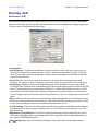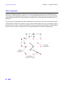
1
Table of Contents
QuickScene2.0
Contents
Chapter 1 - Welcome to Quick Scene 2.0! ...................................................................................................... 1 - 1
Introduction to Quick Scene 2.0 .......................................................................................................................... 1 - 2
Getting Started .................................................................................................................................................... 1 - 2
To our New User .................................................................................................................................................. 1 - 3
What is CAD? ..................................................................................................................................................... 1 - 3
Why use CAD? ................................................................................................................................................... 1 - 3
How do I get started? .......................................................................................................................................... 1 - 3
Compatibility ....................................................................................................................................................... 1 - 3
System Requirements ......................................................................................................................................... 1 - 4
Additional Help Resources .................................................................................................................................. 1 - 4
Chapter 2 - The Quick Tour! ............................................................................................................................. 2 - 1
Steps To Creating A Diagram ............................................................................................................................... 2 - 2
Conventions Used In This Manual ........................................................................................................................ 2 - 2
Correcting Mistakes ............................................................................................................................................ 2 - 4
The Quick Scene Program Screen ...................................................................................................................... 2 - 5
The Drawing Window and the Mouse Pointer ....................................................................................................... 2 - 5
Pull-down menus ................................................................................................................................................. 2 - 5
The Speedbar ...................................................................................................................................................... 2 - 6
Angle Locking .................................................................................................................................................... 2 - 6
Left-Hand Toolbox ................................................................................................................................................ 2 - 6
Selecting Commands from the Toolboxes ............................................................................................................ 2 - 6
Symbol Manager ................................................................................................................................................. 2 - 7
The Symbol Manager .......................................................................................................................................... 2 - 7
Pull-Down Menus, Icons, Toolboxes, or Two-Letter Codes? ................................................................................. 2 - 8
Let’s Get Started ................................................................................................................................................. 2 - 8
Chapter 3 - Program Features ......................................................................................................................... 3 - 1
New (File New, FN) ............................................................................................................................................. 3 - 2
Open (File Open, FO) .......................................................................................................................................... 3 - 3
Close (File Close, FC) ......................................................................................................................................... 3 - 4
Save (DS) ............................................................................................................................................................ 3 - 5
Save As (FA) ....................................................................................................................................................... 3 - 6
Merge (FM) ......................................................................................................................................................... 3 - 7
Import Images (BI) ............................................................................................................................................... 3 - 8
Export Images (VB) ............................................................................................................................................. 3 - 9
Print (PR) .......................................................................................................................................................... 3 - 10
Print Tiling ......................................................................................................................................................... 3 - 12
Advanced Tiling Features .................................................................................................................................. 3 - 14
Print Setup (PT) ................................................................................................................................................ 3 - 16
Exit (FX) ............................................................................................................................................................ 3 - 17
Undo (OO)......................................................................................................................................................... 3 - 18
Redo (RE) ......................................................................................................................................................... 3 - 19
Cut (Ctrl + X) ..................................................................................................................................................... 3 - 20
Copy (Ctrl + C) .................................................................................................................................................. 3 - 21
Paste (Ctrl + V) ................................................................................................................................................. 3 - 22
Quick Edit ......................................................................................................................................................... 3 - 23
Delete (Erase, ER) ............................................................................................................................................ 3 - 24
Break (BR) ........................................................................................................................................................ 3 - 25
Fillet (FI) ........................................................................................................................................................... 3 - 26
Trim/Extend (TR) ............................................................................................................................................... 3 - 28
Double It Up (Offset, OF) ................................................................................................................................... 3 - 29
Window Stretch (WS) ........................................................................................................................................ 3 - 31
TOC - 1
Table of Contents
Quick
Scene2.0
Cutout (CT) ....................................................................................................................................................... 3 - 32
Quick Copy (MC) .............................................................................................................................................. 3 - 34
Explode Symbol (EX) ........................................................................................................................................ 3 - 36
Draw Menu ........................................................................................................................................................ 3 - 37
Line Single (LS) ................................................................................................................................................ 3 - 37
Line Continuous (LC) ......................................................................................................................................... 3 - 38
Arrow (AW) ....................................................................................................................................................... 3 - 39
Rectangle Normal (R2) ...................................................................................................................................... 3 - 40
Rectangle Set Angle (R3) .................................................................................................................................. 3 - 42
Circle (C2) ......................................................................................................................................................... 3 - 44
Arc 3-Point (A3) ................................................................................................................................................ 3 - 45
Curve (CV)......................................................................................................................................................... 3 - 46
Easy Intersection (IW) ....................................................................................................................................... 3 - 47
Easy Streets (EZS) ........................................................................................................................................... 3 - 52
Symbol Manager ............................................................................................................................................... 3 - 54
Templates ......................................................................................................................................................... 3 - 58
3D View (M3) .................................................................................................................................................... 3 - 60
Quick Label (QL) ............................................................................................................................................... 3 - 61
Quick Dimension (QD) ...................................................................................................................................... 3 - 64
Hatch Trace Boundary (HB) ............................................................................................................................... 3 - 67
Hatch Pick Area (HD) ........................................................................................................................................ 3 - 68
Redraw (RD) ...................................................................................................................................................... 3 - 69
Zoom All (ZA) .................................................................................................................................................... 3 - 70
Zoom Window (ZW) ........................................................................................................................................... 3 - 71
Zoom In (ZI) ....................................................................................................................................................... 3 - 72
Zoom Out (ZO) .................................................................................................................................................. 3 - 73
Bring to Front (TF) ............................................................................................................................................. 3 - 74
Send to Back (TB) ............................................................................................................................................ 3 - 75
Preferences (PX) ............................................................................................................................................... 3 - 76
Reset (RV) ........................................................................................................................................................ 3 - 78
Angle Trap On/Off (OT) ...................................................................................................................................... 3 - 79
Layer Manager (MGL) ....................................................................................................................................... 3 - 80
Grid Commands ................................................................................................................................................ 3 - 83
Grid Display (GR) .............................................................................................................................................. 3 - 84
Snap Grid (SG) ................................................................................................................................................. 3 - 85
Grid Size (GS) .................................................................................................................................................. 3 - 86
Grid Origin (GO) ................................................................................................................................................ 3 - 87
Tile Vertical ....................................................................................................................................................... 3 - 88
Tile Horizontal ................................................................................................................................................... 3 - 89
Cascade ........................................................................................................................................................... 3 - 90
Close All Windows ............................................................................................................................................ 3 - 91
Chapter 4 - Creating a Collision Diagram ....................................................................................................... 4 - 1
Lesson 1: Using a Pre-Drawn Template ............................................................................................................... 4 - 2
Lesson 2: Using the “Build Intersection” option. ................................................................................................... 4 - 5
Lesson 3: Adding Symbols ................................................................................................................................ 4 - 10
Lesson 4 - Adding Text to the diagram .............................................................................................................. 4 - 12
Lesson 5 - Placing a Dimension in the Diagram. ............................................................................................... 4 - 14
Lesson 6 - Setting the Line Type/Color of an Object .......................................................................................... 4 - 15
Part 2: Creating a Quick Collision Scene ..................................................................................................... 4 - 16
Easy Intersection Tutorial .................................................................................................................................. 4 - 16
Placing Symbols ............................................................................................................................................... 4 - 20
Place numbers in the Quick Cars ...................................................................................................................... 4 - 21
Placing the remaining symbols ......................................................................................................................... 4 - 22
Saving Your Work .............................................................................................................................................. 4 - 23
Changing Line Types ......................................................................................................................................... 4 - 24
TOC - 2
QuickScene2.0
Table of Contents
Adding Skid Marks ............................................................................................................................................
Placing Text ......................................................................................................................................................
Dimensioning ....................................................................................................................................................
Adding a Leader ................................................................................................................................................
Print Your Diagram ............................................................................................................................................
4 - 24
4 - 25
4 - 26
4 - 27
4 - 28
Chapter 5 - Using the 3D Viewer ..................................................................................................................... 5 - 1
Why 3D? ............................................................................................................................................................. 5 - 2
Compatibility ....................................................................................................................................................... 5 - 2
It All Starts In 2D ................................................................................................................................................. 5 - 3
The 3D Viewer ..................................................................................................................................................... 5 - 3
The 3D Viewer Speedbar ..................................................................................................................................... 5 - 4
Navigating With The Speedbar Commands .......................................................................................................... 5 - 4
Zoom Commands ................................................................................................................................................ 5 - 4
Taking A Snapshot .............................................................................................................................................. 5 - 5
TOC - 3
QuickScene2.0
Chapter 1. - Welcome!
Chapter 1 Welcome to Quick Scene 2.0!
This chapter introduces you to the new Quick Scene Version 2.0 drawing
software. It explains the basic ideas behind CAD, system resource
requirements, and how to get help with the program if you need it.
In this Chapter
• Introduction
• Getting Started
• To Our New Users
What Is CAD?
Why Use CAD?
• Compatibility
• System Requirements
• Help Resources
1- 1
Chapter 1. - Welcome!
QuickScene2.0
Introduction to Quick Scene 2.0
Quick Scene 2.0 was created to fill the needs of Insurance Claims Adjusters,
private investigators, attorneys and any other professionals who need to
create accident scene diagrams faster and easier than ever before. The program contains many special tools that allow the user to easily create accurate
diagrams perfectly to scale, and will save time at the incident scene and in the
office. Even if you are new to computers, Quick Scene 2.0 makes it easy for you
to create professional looking diagrams with a minimum of effort.
Since you have chosen Quick Scene 2.0, you are probably already using other
Windows software applications, like a word processor. You will find that
many features of The Diagram Program are similar to those found in other
Windows programs. This will make it easier for you to learn to use Quick
Scene 2.0 since you will already be familiar with how to use Windows.
Getting Started
Whether you are new to Quick Scene 2.0 or an experienced CAD user, Quick
Scene 2.0 User’s Manual contains vital information you need to know to be
productive in your efforts.
1- 2
Chapter 1. - Welcome!
QuickScene2.0
To our New User
What is CAD?
CAD (Computer Aided Drafting) is an automated drawing system that eliminates the redundant tasks done in manual drafting. When drawing on paper,
you have to redraw an object each time it is used in a drawing. In CAD you
draw an object once, and reuse it as often as you need in the drawing. Your
CAD program is like a toolbox - it contains powerful commands for each of
your conventional drafting tools like the T-square, Templates, and so on.
Quick Scene 2.0 was created for the investigation industry as a low cost, easy to
use alternative to “off-the-shelf” drawing programs like AutoSketch or Visio.
Because of its ease of use and industry specific features, Quick Scene 2.0 is the
only drawing program available for creating accurate professional diagrams and
actually helping to win more cases in the courtroom.
Why use CAD?
The biggest advantage to using CAD is in its accuracy, neatness, and the ability to
modify and update existing drawings quickly and easily. CAD uses precise lines,
not the dots or pixels used in a paint program, so your drawings always look good
in the courtroom. The diagrams drawn in Quick Scene 2.0 are also extremely
accurate and can be updated or modified with new information in just minutes.
With CAD you never need to do something twice! Now, with Quick Scene 2.0
you can import drawings from most other CAD programs including AutoCAD®,
AutoSketch®, Generic CADD®, and previous versions of The CAD Zone’s
Diagram Program® - all with no conversion!
How do I get started?
Make sure to start by taking The Quick Tour in Chapter 2, and working
through the Tutorials in Chapter 4. Doing this will familiarize you with the
basic tools and concepts needed to complete your diagrams successfully. As
you become more experienced with the program, refer to Chapter 3 and the
on-line help for a complete reference of all the program commands.
Compatibility
With Quick Scene 2.0 you can import drawings from most other CAD programs
including AutoCAD®, AutoSketch®, Generic CADD®, and previous versions of
The CAD Zone’s Diagram Program - all with no conversion! Also, the new Quick
Scene 2.0 will allow you to save to .BMP, .WMF, and .JPEG formats for easy
placement into text documents!
1- 3
Chapter 1. - Welcome!
QuickScene2.0
System Requirements
A Pentium PC with Windows 98, 2000, XP, NT 4.0 or later. A VGA monitor
with graphics card, a Windows compatible mouse, 32 MB of RAM and 50 MB of
hard disk space (depending on the options you choose during installation.)
Additional Help Resources
The following resources will help you get the information you need about Quick
Scene 2.0 and assistance with all of your program questions.
The CAD Zone web site at: http://www.cadzone.com
Email support: [email protected]
Phone Support: (503) 641-0334 (Mon - Fri, 9:00 a.m. - 5:00 p.m. PST)
FAX: (503) 641-9077
1- 4
QuickScene2.0
Chapter 2. - The Quick Tour!
Chapter 2 The Quick Tour!
This chapter offers you a “quick tour” of the program designed to familiarize you with the fundamental tools and concepts that are used in Quick
Scene 2.0.
In this Chapter
• The Quick Tour
• Steps To Create A
Diagram
• Conventions Used In
This Manual
• The Program Screen
2- 1
Chapter 2. - The Quick Tour!
QuickScene2.0
Chapter 2: The Quick Tour
On the following pages you will find a “quick tour” of Quick Scene 2.0. This tour is
intended to get you familiar with the basic tools and concepts you need to understand in order to use the program efficiently.
Your success with the program depends on how you apply the information
included in this manual. Quick Scene 2.0 is a tool, and like any tool it takes practice to become an expert. As you spend more time using the program, you will gain
the ability to create all your diagrams more quickly and efficiently than ever.
As you start to work through the methods and features introduced to you in
this chapter, keep in mind that only the most basic commands are being
introduced here. Refer to this manual and the on-line help to learn how to
draw with even greater accuracy and speed using the rest of the program
command features.
Steps To Creating A Diagram
Here are the general steps for creating a diagram, although you may want to
change the order of some of the steps to best apply to your particular diagram:
1) Start Quick Scene 2.0 and use the “Let’s Get Started” wizard to set up a
new drawing, load a drawing template, or run the Easy Intersection toolbox.
2) Draw the basic features of the scene using the program’s custom
drawing tools. These could include a street, intersection, or even a
building.
3) Use features from the Speedbar or the Draw Pull-Down menu to draw
nearby streets, drives, parking lots, fences, railroad tracks, and other
details around the scene.
4) Insert symbols for the various portions of the diagram such as vehicles,
road signs, curbing, and road conditions.
5) Label your diagram and add dimensions with the text and dimension
features in the program.
6) Save your diagram to disk and print it.
Conventions Used In This Manual
As you begin working in Quick Scene 2.0, some terms may be unfamiliar to you,
especially if you are new to CAD. Use the following guidelines to become
acquainted with the basic terms and ideas presented in this manual.
2- 2
Chapter 2. - The Quick Tour!
QuickScene2.0
Normally, in this manual, you will be given a summary of the task to perform and
then the exact step-by-step instructions will be listed. These instructions are shown
in a different font, and are indented for easier identification. For example, you are
commonly given an instruction like this:
Click on the vehicle to select it.
Here, you would move your mouse pointer until it is on the vehicle symbol
and then click your left-mouse button once quickly.
Double click on the Vehicles Symbols Folder
Here, you would place your mouse pointer on the folder named Vehicles and
rapidly click the left-mouse button twice. Another common instruction is:
Select the “Draw” pull-down menu.
Here, move your mouse pointer up to the menu headings at the top of the
program screen, place your mouse pointer on the menu called “Draw” and
click the left-mouse button. Once the menu is displayed, you can then click
on a command name to select it.
You may also be instructed to select commands this way:
Select “Easy Intersection” from the left-hand toolbox.
Here, position your mouse pointer so it is on the Easy Lines button (located
on the left-hand toolbox) and click once with your left-mouse button.
When you are prompted to click on an icon, or when you are prompted to
select a command, the equivalent toolbar icon will be shown in the column.
When you are drawing or editing objects, you may be instructed in this way:
Click near point A.
Here, click your mouse near the approximate location on your screen
identified by the letter “A” on the designated figure. To attach exactly to a
specific point (like the endpoint of a line) you will be instructed like this:
Snap to point A
There are several ways to snap, or attach, exactly to a specific point. The
easiest way to do this is to use the “Autosnaps” feature. When this command
is turned on, you position the mouse pointer’s crosshairs near the point
labeled “A” and click the left-mouse button. This causes the mouse to “jump” or
snap exactly to the closest endpoint, center of a circle, or center of an arc.
2- 3
Chapter 2. - The Quick Tour!
QuickScene2.0
You can also type 2-letter keyboard shortcuts to perform most of Quick
Scene’s commands. When you are prompted to select a command, the
equivalent two-letter keyboard shortcut will be shown in uppercase
parenthesis. For example, if you see this, you would type SA:
Save (SA)
Correcting Mistakes
As you begin to draw, you are bound to make mistakes, so Quick Scene 2.0
provides you with the commands Undo (OO), and Redo (RE), found on the Edit
Pull-Down menu.
The Undo command will let you undo the last command that was performed
during the current drawing session. If you need to Undo multiple commands,
select Undo again to undo the second command. For example, if you need to
undo the erasing of ten individual objects, you would have to select Undo ten
times to bring them all back.
The Edit commands can also be used to help correct mistakes. Use commands
like Erase, Copy, Trim/Extend, and Stretch to change objects in the diagram
that were not placed exactly the way you want them to be.
If the screen looks a little cluttered after all the erasing, undoing, rotating, and
so on, select the Refresh command either from the View pull-down menu, or
the Speedbar.
Remember that you can also use the Esc key to abort a command. If you select the
wrong item from the menu, pick the wrong point, or want to start a command over,
press the Esc key. For commands that require multiple operations or points to be
set, pressing Esc backs you up a single step, instead of completely terminating the
command. For instance, if you’re drawing the outline of a building using the Line
command and you set a point incorrectly, just press Esc and re-select that point.
Each time you press Esc while in the Line mode, you’ll go back to the previous
point that was set until the Line command is finally aborted.
2- 4
Chapter 2. - The Quick Tour!
QuickScene2.0
The Quick Scene Program Screen
When you start Quick Scene, the first thing to appear on your computer monitor is
Quick Scene’s program screen. The program screen has everything you need to
draw a complete diagram conveniently located on one screen, - all the program
commands and tools, and the drawing window.
Menu Bar
Every command can be
selected from the pull-down
menus.
Speed Bar
Left-Hand Toolbox
Contains the Draw/Edit, Set Line/
Color, Symbols, Templates, Easy
Intersection, and Learning Center
toolboxes.
Drawing
Window
The area where you create your
diagrams.
Message Bar
Displays step-by-step instructions
for using the program commands.
The Drawing Window and the Mouse Pointer
The Drawing Window is the large, blank area that covers the center portion of the
screen. This is the area where you draw your diagram. Everything else you see on
the screen are the individual tools that help you get the exact diagram that you
want.
Inside the Drawing Window is a floating pointer that you control by moving your
mouse. The mouse pointer is used to select features from the menus and toolboxes,
perform the drawing functions, and place objects in the diagram. The mouse
pointer starts as an arrow, but may change shape depending on which feature you
are using. The Arrow Pointer is used to represent the “selection mode” which
means the program expects you to select an object or command from the program
screen.
Pull-down menus
All of the program’s commands and special features can be executed from the Pulldown menus. Most of these commands and special features can also be selected
from the speedbar and left toolboxes. Most of the commonly used commands can
also be performed by typing in their two-letter code on the keyboard.
2- 5
Chapter 2. - The Quick Tour!
QuickScene2.0
The Speedbar
The Speedbar, located just below the pull-down menus, provides a shortcut for the
most powerful, commonly used commands. The speedbar commands can also be
selected from the pull-down menus and the left toolbox, but the speedbar provides
the fastest way of selecting them.
Angle Locking
The Angle Locking Draw feature simplifies drawing lines by automatically
straightening the line you are drawing when you come within five degrees of
horizontal or vertical.
For instance, when you select the line command you click once on the
drawing screen to place the first point of the line. At this point you can move
the cursor in any direction. Notice that anytime your cursor moves within 5
degrees of horizontal or vertical, it will automatically straighten out. When
your line is at the desired angle, click the left-mouse button a second time to
finishing placing it.
Left-Hand Toolbox
The Left-Hand Toolbox runs along the left portion of the drawing window. While
all of the commands can be found on the Pull-Down menus, the Left-hand Toolbox
offers a quicker way to select many of them. The commands found on the toolbox
are arranged in “Bins” (groups) of similar features such as drawing and editing,
setting line/color properties, Symbols, Templates, Easy Intersections, and The
Learning Center.
Left-Hand Toolbox.
Selecting Commands from the Toolboxes
To see all of the command icons in a bin, position the mouse pointer on the desired
bin, and click the left-mouse button. All of the command icons are displayed at the
top of the toolbox.
Opening the Draw Bin
Selecting Commands
from the Bins.
2- 6
To select a command from the displayed bin, just click the left-mouse on the
command’s icon.
Chapter 2. - The Quick Tour!
QuickScene2.0
Symbol Manager
Quick Scene includes many pre-drawn symbols that you can insert into any of your
diagrams. Once placed into a diagram, symbols can be moved, rotated, erased, or
copied just like any individual line or circle.
Since so many symbols are included in the program, they have been divided into
several different groups and are sorted in the Symbol Manager. To open a different
set of symbols, simply click on a different group label.
To place a symbol, first click on the desired symbol category icon on the Symbol
Manager to open it. Next, pick the desired symbol
from the Icons that appear in the bottom window of the
Symbol Manger. Before you identify the symbol’s
location in the diagram the program shows you a ghost
image outline of the symbol to show you its size and
orientation. Move your cursor back into the drawing
window to see the symbol’s ghost image. You can also
change the symbol’s rotation or color by clicking the
appropriate icons on the Symbol Manger before you
even place the symbol in the drawing!
To place a symbol click once in the drawing to anchor
the symbol. Move the cursor to establish the symbol’s
direction and click again.
Dynamic Symbol Scale
2- 7
You can also adjust the size of any symbol as you place
it by selecting the Dynamic Symbol Scale feature,
located on the Symbol Manger. Select the Dynamic
Symbol Scale Icon and set the symbol’s first handle, as
you would do normally. Now as you move the mouse
pointer the size of the symbol’s ghost image grows or
shrinks depending on the position of the mouse pointer.
Click the second point when the symbol’s ghost image The Symbol Manager
has reached the desired size and angle. The Dynamic
Symbol Scale feature is a “toggle” switch command and remains in effect until you
select the command again to turn it off.
QuickScene2.0
Chapter 2. - The Quick Tour!
Pull-Down Menus, Icons, Toolboxes, or Two-Letter Codes?
So, what is the best way to select a command - use the menus, toolboxes,
Speedbar Icons, or keyboard commands? There really is no “best” way. You
simply use whatever method is the most convenient at the time. The more you use
the two-letter commands and the speedbar, the more likely you are to memorize
the commands associated with them. Using them can provide a significant shortcut
over searching through the pull-down menus. Throughout this manual, all of the
different methods will be used so you can become familiar with the flexibility of the
program.
Let’s Get Started
The Let’s Get Started dialog box is designed to help you get started drawing faster
than ever before! With shortcuts to setting up a new drawing, your existing
drawings, the electronic User’s Manual, quick-time tutorial movies, and links to online technical support, the learning center will help you master Quick Scene 2.0 in
no time!
When you first open the program the “Let’s get started” screen is displayed. From
there you can select to: Create a new drawing, open an existing drawing, or open
the Learning Center.
Opening an Existing Drawing
Choose this option to load an existing drawing that you created previously with
Quick Scene 2.0.
Click the “Open Existing Drawing” button on the Let’s Get
Started” dialog box.
Scroll through the diagrams listed in the “Open a Drawing”
window, or click the Browse button to search for another
folder. The Other Drawings button allows you to open files of
other types like Laser Technology .RAW files.
Select the diagram you wish to open and click the OK button
to load it into the Diagram Program.
2- 8
Chapter 2. - The Quick Tour!
QuickScene2.0
Start From Scratch
Choose this option to create a new drawing with Quick Scene 2.0.
Click the “Start From Scratch” button on the Let’s Get Started
dialog box.
Step One prompts you to click in the Drawing Name field and type in
the desired name of your drawing.
Step Two prompts you to pick the approximate site size. Choose
from small, medium, large or custom size options.
Step Three prompts you to select a method of adding an
intersection. You are given three options:
• Pre-drawn Template - Opens the “Load a Template” toolbox,
allowing you to choose from several pre-drawn intersections.
• Build an Intersection - Opens the Easy Intersection toolbox,
allowing you to create your own custom intersection.
• No Method - Draws a border to the size that you chose in Step
One, allowing you to create a diagram completely from scratch.
Click the OK button to load the intersection you just created in
the drawing screen with the drawing name you assigned it.
The Learning Center
Choose the Learning Center option to gain access to Help File Topics, Electronic
Tutorials, Movies, Manuals, and to the CAD Zone’s internet Web Site, which
features a Discussion forum with more on-line help.
Click the “Learning Center” button on the Let’s Get Started
dialog box.
Click the topic that you would like to see displayed in the
learning center window. For example, clicking the Movies topic
2- 9
QuickScene2.0
Chapter 2. - The Quick Tour!
displays all of the quick-time available.
Scroll through all of the movie titles displayed in the learning
center window. Click on the desired movie title to run that
movie.
If you don’t want the Learning Center dialog box to appear again, click the
checkmark option labeled “don’t show this dialog again”
2- 10
QuickScene2.0
Chapter 3. - Program Features
Chapter 3 Program Features
This chapter introduces you to the program features and explains the
program commands in detail.
In this Chapter
• Instruction on how to
use every command in the
program.
3- 1
QuickScene2.0
Chapter 3. - Program Features
File Menu
New (File New, FN)
Use the New command to start a new drawing from scratch. Quick Scene assigns the first file created
within a drawing session the name UNTITLED1, the second file UNTITLED2, and so on.
Quick Scene automatically sets up the drawing environment for a new file based on preferences you
have specified when saving other drawings, or on defaults shipped with the program.
To start a new drawing:
Start Quick Scene without specifying an existing drawing file to load.
or
If Quick Scene is running, choose the New command.
3-2
QuickScene2.0
Chapter 3. - Program Features
Open (File Open, FO)
Use the Open command to continue work on a drawing, or to load an AutoCAD, Generic CADD, or
DXF-format file as a Quick Scene file.
To open an existing drawing file, using the Open command:
1.
Choose the Open command.
2. If necessary, in the List Files of Type list, change the file type.
(By default, Quick Scene lists files with the CZD extension. You can also select AutoCAD (.DWG)
files, .DXF files, Generic CADD (.GCD) files, Quick Scene (.CZD) files, or previous CAD Zone
(.DW2) files.)
3. If necessary, change the path and drive in order to locate the file you wish to open.
4. In the list box, double-click the file name, or select the file name and click OK.
Tip:
If you want the program to remember the file path so the same path is displayed the next time you open
a file, check the “Save Current Path” box.
3-3
QuickScene2.0
Chapter 3. - Program Features
Close (File Close, FC)
Use the Close command to close the active drawing file, either prior to exiting Quick Scene or before
opening another drawing. Having only one drawing file open at a time will conserve memory.
To close the current drawing:
Choose the Close command.
Quick Scene remains active after the drawing file closes, but will only display the File and Help menus.
3-4
QuickScene2.0
Chapter 3. - Program Features
Save (DS)
Use the Save command to save your drawing data. Save often during a drawing session as protection
against power outages or computer crashes, and save at the end of a drawing before exiting Quick Scene.
This command saves the drawing to disk under the current name.
To save the current drawing:
Choose the Save command.
If the file has been previously saved and named, Quick Scene saves the file under the current name.
If the file has not yet been saved, Quick Scene displays a Save File dialog box where you can name the
file and set the path location, as described for the Save As command.
3-5
QuickScene2.0
Chapter 3. - Program Features
Save As (FA)
Use the Save As command to rename and save a drawing with another name, or to save a copy of an
existing drawing so that it can be used as the base of a new drawing. Save As preserves the last-saved
version of the file, and saves a copy under the name you give it.
You can also use this command to save the file into a different file format, so that it can be used with
other computer-aided drawing programs.
To save a drawing under a new name:
1. Choose the Save As command.
A dialog box appears with a list of existing drawings displayed in the current path. This dialog box
functions just like that found in other Windows programs.
2. If necessary, change drives or paths to place the drawing in the location of your
choice.
3. If necessary, change the drawing extension in the Type box to one of the other supported file types.
This causes the file to be saved in the selected file type so that the drawing can be read by other drawing
or CAD programs.
4. Type a name for the file in the File Name box.
5. Click OK.
The drawing is saved in the chosen format, name, drive and path. The new file name is displayed at the
top of the drawing window.
3-6
QuickScene2.0
Chapter 3. - Program Features
Merge (FM)
Use the Merge command to combine the contents of two drawings. The name and drawing environment
of the first drawing loaded are maintained, and all the symbols and attributes of the second drawing are
added to those of the first (conflicts, such as duplicate symbol names are resolved in favor of the first
drawing).
To merge another drawing file into the current drawing:
1. Choose the Merge command. Remember that both files that you are trying to merge
must both be .CZD files.
2. If necessary, change the path and drive in order to locate the file you wish to merge.
3. In the list box, double-click the file name, or select the file name and click OK.
Once loaded, the merged file will be represented by an “extent” box that is attached to the cursor at the
lower left corner. (An extent box is a box that represents the outer edges of your drawing.)
4. Drag the extent box of the merged file to the desired location, then click to place the
merged drawing in place.
Tip:
If you want the same file path to be displayed the next time you merge a file, check the “Save Current
Path” box. Also remember that you can only merge files that are both .CZD files.
3-7
QuickScene2.0
Chapter 3. - Program Features
Import Images (BI)
Use this command to import Bitmap (.BMP) and JPEG (.JPG) files into a diagram. Once placed in a
diagram these images can be viewed, printed, or moved. However, you can not modify the images in any
way. They are treated as a single object in the diagram.
To import an image:
1. Choose the Import Images command from the File menu.
2. Click (or snap) to place two, diagonal points in the diagram where you want to place
the image.
A dialog box appears that allows you to select the desired image file.
3. Using standard Windows methods, select the proper drive and folder, then select the
desired image file. Normally only .BMP and .JPG files are listed.
The image is inserted into the diagram at the location specified earlier.
Files from other CAD programs, such as AutoCAD and Visual CADD, or files of type .DXF can be
imported into Quick Scene with the Open File command.
3-8
QuickScene2.0
Chapter 3. - Program Features
Export Images (VB)
Use this command to export diagrams out of the program in Bitmap (.BMP) Metafile (.WMF) and JPEG
(.JPG) format. Once saved these images may be used by other applications such as Microsoft Word or Lotus
Notes.
To export an image:
1. Choose the Export Images command from the File menu.
A dialog box appears that allows you to select the desired image format that you wish to save in.
2. Using standard Windows methods, select the proper drive and folder, then select the
desired image file. Normally only .BMP and .JPG files are listed.
The image is saved in the specified file type.
.
3-9
QuickScene2.0
Chapter 3. - Program Features
Print (PR)
The Print dialog can also be accessed from the main speedbar icon by typing the 2 letter command, PR.
The dialog maintains all the settings for accessing and controlling the printed output. The available
options allow for full control over standard print features such as orientation and size along with a
variety of options for improving print output and performance.
Printer - the printer section displays the currently active printer. To change the printer select the
“Setup..” button.
Page Size - the page size is dependent on the installed printer. To change the page size or review other
sizes supported by the current driver select the “Setup…” button.
Print Scale - the print scale setting displays the current scale factor for printing. The value is only used
when the scale option is selected. Values are entered in paper units versus real world coordinates. For
example, 1 in. = 48 in. will print the drawing at quarter inch scale (48"/12" = 4’). The Real World units
always reflect the smallest unit in the current system settings. For example, when the current units are
“ft.-in.” the smallest unit is the inch.
Fit to Paper, Current View or Scale - defines the mode the current print job is to use. The drawing can
be scaled automatically to fit the current paper size, scaled to display the current view to fit the page or
to a factor entered.
Portrait or Landscape - determines the paper orientation between horizontal (landscape) or vertical
(portrait).
Print to File - send the output to a file on disk. Quick Scene will prompt for a file path and name after
the “Print” button is selected.
3 - 10
QuickScene2.0
Chapter 3. - Program Features
Print Continued
Time/Date Stamp - includes a time and date stamp on the printed page. The location of the time stamp
are controlled by settings in Windows.
Selection Only - prints only the selected entities in the drawing.
Copies - sets the number of copies to print.
Preview - shows a preview of the drawing as it will print using the current settings.
Center - centers the drawing on the given page based on the current margin settings.
Setup - used to select a new printer or initiate the driver setup for the active printer. The print routine
utilizes the Windows drivers provided by the printer manufacturers. These drivers contain printer specific settings that may improve overall print performance. The drivers vary between printer and printer
manufacturer. For details on options available through the driver please refer to the printer manufacturers documentation.
Update - used to update the print preview screen after changes have been made to the print settings.
Print Setup - Use this command to display the Print Setup dialog box. The Print Setup dialog is used to
select a new printer or initiate the driver setup for the active printer. The print routine utilizes the Windows drivers provided by the printer manufacturers. These drivers contain printer specific settings that
may improve overall print performance. The drivers vary between printer and printer manufacturer. For
details on options available through the driver please refer to the printer manufacturers documentation.
To display the Print Setup dialog box:
1. Choose the Print Setup command, or click Setup in the Print dialog box.
Make changes as necessary to the settings for printer.
2. Click Properties to display a dialog box of printer-specific options like , paper size,
3 - 11
QuickScene2.0
Chapter 3. - Program Features
Print Continued
page orientation, and paper source. The driver information is also available through the
Window Print Manager. In Windows 95 select the start button on the taskbar and choose
Setting ~ Printers.
3. Click OK to accept the printer setup options.
Tip:
The Print command uses the standard Windows drivers for output to the printer. If your printed drawing
does not look like the one on the screen or if you have other problems printing, you may need to obtain
updated printer drivers from your printer manufacturer. You can normally call your manufacturer for
more information or visit their web page and download new drivers from there.
Print Tiling
When printing diagrams to an exact scale, it is possible to specify a scale that does not allow the diagram to fit
on one sheet of paper. In this case the program automatically uses Print tiling to divide the drawing up so it can
be printed on multiple sheets. If you don’t have access to a large-scale plotter, print tiling gives you the ability to
print your diagrams on multiple sheets and tape them together to construct a larger print.
A single sheet of 8.5" x 11" paper is commonly referred to as an A-size sheet of paper. A B-size sheet of
paper is 11" x 17", or two A-size sheets taped together side-by-side. A C-size sheet of paper is 17" x
22", or four sheets of A-size taped together in two columns and two rows. This process continues
upward. If you don’t have a large paper plotter, print tiling gives you the ability to piece together any
number of A-size sheets to construct your own “plot.”
Using the Print Tiling Feature:
3 - 12
QuickScene2.0
Chapter 3. - Program Features
Print Continued
1. To use Print Tiling, the Scale radial button must be selected. The other two selections
do not allow tiling. Fit to Paper will fit the entire diagram on a single sheet of paper.
Current View will display the current zoomed view of the diagram on the drawing screen
and print out on a single sheet.
2. The Print Scale must be set to a scale that requires more then one sheet of paper to
print the drawing. As the scale value decreases, the number of required panels increases. For example, it takes more panels to print a diagram at a scale of 1" = 20' than
at a scale of 1" = 50'.
3. After setting the scale, click on the Update button to see your results. You will need to
click Update each time you enter a new scale to see the effect that scale value has on the
print.
Tip:
If you want to optimize how your drawing fits on the paper, try switching between Portrait and Landscape orientation. In some cases this will result in fewer panels needed to print out the drawing.
4. The message below the preview window shows the number of panels required with
the number of columns (number of panels horizontally) and number of rows (number of
panels vertically) shown in parenthesis.
5. By default all the panels will be printed. If you want to just print individual panels,
click on the ones you want to print to select them.
6. Select the Print button to print out all of your selected panels. A message will appear
telling you how many panels you’re about to print, giving you a chance to Cancel the
print if this number is not what you intended.
3 - 13
QuickScene2.0
Chapter 3. - Program Features
Print Continued
Advanced Tiling Features
Close After Print
If this box IS NOT checked, you will be returned to the print dialog after each print so you can continue
with other print jobs. If this box IS checked then the print dialog box automatically closes each time you
click the Print button and you are returned to the drawing screen. Whenever the print dialog is closed,
the drawing re-center’s itself and any previously selected tiles are deselected. Other settings may be affected as
well.
Printing Individual Panels: You can click on individual
panels in the print preview window. Each panel you click
on is highlighted with a yellow background. When you
select the Print button, only the selected (highlighted) panels
will print. This will come in handy if you want to print out a
particular piece of the drawing or if you want to avoid
printing blank panels.
Tip:
You may have blank panels depending on the shape
(content) of the drawing especially if you drag the drawing
to fit better in the panels and intentionally drag the drawing out of some panels.
Positioning the Drawing: Once the scale and the number of panels has been established you can drag
the drawing around inside the panels. Depending on the shape of the drawing, you might be able to get
the drawing to fit better by moving it within the panels. Just move your cursor over the display, hold
down your left mouse button, and drag the drawing to a new position.
Page Marks and Stamps
3 - 14
QuickScene2.0
Chapter 3. - Program Features
Print Continued
Since your printer can’t print all the way to the edge of a sheet of paper (there is always a required margin) you
will need to trim your panels before taping them together. In the Stamp section of the print dialog you’ll find
selections for Page Marks including None (no page marks), Corner, or Outline.
Use Corner marks if you have a paper cutter that allows you to lay down a sheet of paper, line
up the corners, and pull down the blade to trim the edge away.
Use Outline if you intend to use scissors to trim the excess paper away.
The Stamp selections, if checked, will print the selected stamp(s) at the bottom of EACH page,
including the page number, filename, date printed, and drawing scale. If you have many panels to print,
you may not want all of the stamps (such as filename and date) printed on each page. In this case, click
on just one panel to select it, and print that panel with all the stamps. Then turn off those stamps and
print the remaining panels with just the page numbers.
3 - 15
QuickScene2.0
Chapter 3. - Program Features
Print Setup (PT)
Use the Printer Setup command to display the Printer Setup dialog box. The Printer Setup dialog is used
to select a new printer or initiate the driver setup for the active printer. The print command uses the
Windows drivers provided by your printer manufacturer. These drivers contain printer specific settings
that may improve overall print performance. The drivers vary between printer and printer manufacturer.
For details on options available through the driver please refer to the printer manufacturer’s documentation.
To display the Printer Setup dialog box:
1. Choose the Printer Setup command, or click Setup in the Print dialog box.
Make changes as necessary to the settings for the printer.
2. Click Options to display a dialog box of printer-specific options like , paper size, page
orientation, and paper source. The driver information is also available through the Window Print Manager. In Windows 95 select the start button on the taskbar and choose
Settings…Printers.
3. Click OK to accept the printer setup options.
3 - 16
QuickScene2.0
Chapter 3. - Program Features
Exit (FX)
Use the Exit command to exit Quick Scene. If unsaved drawings are loaded, Quick Scene prompts you
to save the drawing files before closing the program.
To exit Quick Scene :
Choose the Exit command.
3 - 17
QuickScene2.0
Chapter 3. - Program Features
Edit Menu
Undo (OO)
Use the Undo command to reverse one or more of your last commands. Any operation that changes the
drawing can be reversed. For example, erased objects are restored, drawn objects are removed and
moved objects are replaced in their original positions. Operations that do not change the entities in the
drawing such as zoom commands, selections, hiding/displaying of layers, settings, and so on, are not
affected by the Undo command.
To reverse the last operation performed:
Choose the Undo command.
The last operation is undone; a drawn object will disappear, an erased object will reappear, etc.
Tip:
If you accidentally undo an operation, you can use the REDO command to cancel the undo.
3 - 18
QuickScene2.0
Chapter 3. - Program Features
Redo (RE)
Use the Redo command immediately after an Undo command to reverse the effect of the Undo command by “redoing” the command. If several consecutive operations were undone, Redo can be used
repeatedly to restore each one.
To redo the last operation undone:
Choose the Redo command.
The last undo operation is canceled.
3 - 19
QuickScene2.0
Chapter 3. - Program Features
Cut (Ctrl + X)
Use the Cut command to move objects to different locations in your drawing or to other drawings or
other Windows applications. Cut removes the selected objects from the drawing and places them onto
the Windows clipboard. Use the Paste command to copy these objects from the clipboard back into a
drawing or into another Windows application.
To cut objects from the drawing onto the clipboard:
1. Select the objects to be removed from the drawing and placed on the clipboard.
2. Choose the Cut command.
The selected objects disappear from the drawing and are placed on the clipboard.
3 - 20
QuickScene2.0
Chapter 3. - Program Features
Copy (Ctrl + C)
Use the Copy command to copy objects from your drawing to other locations in your drawing, to other
drawings or to other Windows applications. Copy places these objects onto the Windows clipboard. Use
the Paste command to paste them from the clipboard back into your current drawing, into other drawings
or into other applications.
To copy objects onto the clipboard:
1. Select the objects to be copied to the clipboard.
2.
Choose the Copy command.
The selected objects remain in the drawing but are also copied to the clipboard.
3 - 21
QuickScene2.0
Chapter 3. - Program Features
Paste (Ctrl + V)
Use the Paste command to copy information from the Windows clipboard into your drawing or into
other Windows applications.
To paste objects from the clipboard into your drawing:
1. Choose the Paste command.
A box indicating the extent (width and height) of the clipboard contents appears, attached at the upper left corner to the cursor. You drag this box to position the contents
in the drawing.
2.
Click to paste the clipboard objects into the drawing.
The clipboard contents are pasted into the drawing. The objects remain in the clipboard,
ready to be placed elsewhere.
3 - 22
QuickScene2.0
Chapter 3. - Program Features
Quick Edit
Use this command to preset the properties (the color, and line type, etc. ) to be used for drawing future
objects.
To preset object properties:
1. Choose the Set Line/Color button from the Left-Hand menu.
2. Select the properties that you want to apply, such as a new line type or color.
These properties will be applied to any objects drawn from then on, until the properties
are changed again.
3 - 23
QuickScene2.0
Chapter 3. - Program Features
Delete (Erase, ER)
Use the Delete (or Erase) command to delete unwanted objects.
To delete objects from your drawing:
1. Select the objects to be deleted.
2. Choose the Delete command or press the Delete key on the keyboard. The objects
will be deleted.
Tip
Like other drawing and editing commands, Erase is reversible. To restore an item or selection that has
been erased, click the Undo button on the Modify menu or hold down Ctrl and press Z on the keyboard.
3 - 24
QuickScene2.0
Chapter 3. - Program Features
Break (BR)
Use the Break command when you want to break a gap or hole in an object. For example, you may want
to insert an opening in a wall for a door or window.
To create a break in an object:
1. Select the object that you want to break.
2. Place a point at or near where you want the break to begin.
This point need not be exactly on the object; the break will start at the point closest to
the point you place. However, if you want to break the opening at an exact location be
sure to place Markers (use Easy Lines command) and then Snap exactly to them.
3. Move your mouse and a dynamic preview of the break appears, shadowing the cursor movement.
4. Place a point at or near where you want the break to end.
3 - 25
QuickScene2.0
Chapter 3. - Program Features
Fillet (FI)
Use the Fillet command to create rounded corners between lines, arcs, and rectangles.
To fillet two objects:
1. Choose the Fillet command.
2. A dialog box appears where you can set the Fillet Radius:
Enter a new radius in the “Fillet Radius” text box.
3. Click the first line or arc to be filleted.
4. Click the second line or arc to be filleted.
3 - 26
QuickScene2.0
Chapter 3. - Program Features
Fillet continued
Move your cursor around the intersection and notice the preview of the fillet arc moves
from corner to corner.
5. Click when the preview fillet arc is in the correct location.
The filleted objects will be trimmed automatically to meet the fillet arc exactly at the
tangent points.
3 - 27
QuickScene2.0
Chapter 3. - Program Features
Trim/Extend (TR)
Use the Trim/Extend command when you want to trim or extend an object so it ends exactly at another
object. You can use this command to trim or extend lines, continuous lines, arcs, and curves. For example, when creating an intersection you can trim or extend a line that represents one side of a street so
it ends exactly at another line.
To trim or extend an object to another “target object”:
1. Choose the Trim/Extend command.
2. Click the object to be trimmed.
Tip:
If you are trimming the object, be sure to click on the side of the object that you wish to keep.
3. Click the target object.
The first object will be trimmed or extended so it ends exactly at the second target
object.
3 - 28
QuickScene2.0
Chapter 3. - Program Features
Double It Up (Offset, OF)
Use the Double It Up command to draw parallel objects to lines, continuous lines, polygons, curves, circles,
arcs, and ellipses.
To draw a parallel object:
1. Select the object or objects to be copied and used as the “base” for the parallel object.
2. Choose the Double It Up command.
A Settings Bar will appear that displays the current “Offset distance.” This is the distance
between the original object and the new, parallel object that is to be drawn.
The Settings Bar also displays a check box marked “Fixed”. When this box is checked,
the offset distance is set to the value specified in the “Offset distance” box, and moving
the cursor will simply allow you to pick on which side of the original object you want the
parallel object to be drawn. If the Fixed box is not checked, the parallel object moves
freely as you move the cursor, and the distance between the two objects is dynamically
displayed in the Offset distance box.
Tip:
If more than one object is selected to be doubled up, a fixed offset distance must be entered, i.e. there is no
rubberbanding preview as with single objects.
3 - 29
QuickScene2.0
Chapter 3. - Program Features
Double It Up continued
3. If you want to specify a numeric offset distance, check the Fixed box, and enter the
desired offset distance in the Offset distance box.
4. Move your cursor from side to side of the original object and notice the preview of the
parallel object being drawn.
5.
When the parallel object is in the desired location, click to place it.
3 - 30
QuickScene2.0
Chapter 3. - Program Features
Window Stretch (WS)
Use the Window Stretch command to stretch objects to a new size or shape. The area to be stretched is
defined by two points set in opposite corners of a selection box. Then a point is set for the original
location of the reference point. A second point is set for the new position of this point. The objects
contained in the area are stretched so that the first point that was set is moved to the new location.
To stretch selected objects:
1. Select the Stretch command from the Edit/Modify menu or the Left-Hand Toolbox.
2. Set two points to draw a box that encloses the endpoints of the objects to be
stretched (Step 1 below).
3. Set a reference point to define the original location (Step 2 below).
4. Set a point for the new location of the reference point (Step 3 below).
3 - 31
QuickScene2.0
Chapter 3. - Program Features
Cutout (CT)
Use this command to “cut-out” a selected portion of a drawing. The cut-out section remains selected so you can
save it as a new diagram file or modify it using any of the commands found on the Edit menu.
The Cut-out command works on any line, hatch, fill or text in the drawing, allowing for a more precise
selection than was available in previous versions of the program.
To cut-out a section of diagram:
1. Choose the Cut-out command from the Edit menu.
The message bar prompts you to place a polygon (selection window) around the region to be cut-out.
2. Click to place the first corner of the cut-out box just to the outside of the objects you
wish to select.
3. Move your mouse to the other corner of the selection area and notice the selection
window rubberbanding from your original point.
3 - 32
QuickScene2.0
Chapter 3. - Program Features
Cutout continued
4. When all the objects you wish to select are completely enclosed in the window, click
the mouse again to finish the selection.
Any lines or objects that are enclosed in this box are now broken and remain selected so you can move,
modify, or save them as a new diagram file.
3 - 33
QuickScene2.0
Chapter 3. - Program Features
Quick Copy (MC)
Use this command to make multiple copies of objects at user defined points within the drawing. Unlike the
standard Copy or Rows & Columns Copy, this command allows you to continue to place individual copies by
simply clicking until the command is ended.
To make quick, multiple copies of an object:
1. Select the object or objects you wish to duplicate.
2. Click the Quick Copy Tool.
3. Click to define a reference point - the point at which the objects will be copied from.
An image of the object now follows your cursor around the drawing area.
4. Click to place the reference point of the duplicate objects at the new point.
3 - 34
QuickScene2.0
Chapter 3. - Program Features
Quick Copy continued
5. Repeat step 4 as many times as desired
6. To end the command either double-click the mouse to place the last copy, or press the
Enter key.
Tip: Press Escape on the keyboard if you wish to change the original reference point.
3 - 35
QuickScene2.0
Chapter 3. - Program Features
Explode Symbol (EX)
You use the Explode command to explode continuous lines or symbols that have already been placed in a
drawing. You must explode symbols before you can change properties of the objects that make them up (like
color, line width or line type). Symbols can be scaled or rotated but you cannot make design changes within a
symbol unless you first explode it.
To explode symbols or continuous lines already placed in the drawing:
1. Select the symbol(s) or continuous lines that you wish to explode.
2. Choose the Explode command.
The objects are exploded into the entities that make them up. You can then select the
individual objects and use the Edit command to change their properties.
You can also explode symbols as you place them so that instead of a symbol, the individual objects that make
it up are placed in the drawing. To explode symbols as you place them:
1. Bring up the Symbol Manager.
2. Click the Explode Upon Placement button (the stick of dynamite) and make sure it is
pressed which shows the option is turned on.
3. Select a symbol and place it in the drawing normally.
Click anywhere on the symbol that was just placed and notice that only an individual
object is selected, not the entire symbol. This shows that the symbol is exploded.
3 - 36
QuickScene2.0
Chapter 3. - Program Features
Draw Menu
Line Single (LS)
Use the Single Line command to draw a single line by specifying a start and end point.
To draw a single line:
1. Choose the single line command.
2. Click or snap to place the starting point.
3. Click or snap to place the ending point.
Tip:
If you are drawing lines to exact measurements, you can use direction-distance entry to place the ending
point. Just place the starting point, move the cursor in the direction you want the line to go and type in
the line’s length on the keyboard.
Tip:
When drawing lines you can use the Angle Draw buttons to restrict the cursor so it only moves at specific angles. This allows you to draw lines at exact angles.
3 - 37
QuickScene2.0
Chapter 3. - Program Features
Line Continuous (LC)
Use the Continuous Line command to create a continuous line consisting of one or more line segments.
Continuous lines may be selected and edited as single objects.
To draw a continuous line:
1. Select the Continuous Line command.
2. Click or snap to place the starting point.
3. Click or snap to place the end point of the first line segment.
This point also becomes the starting point for the second line segment.
4. Place additional points to create the line segments of the continuous line.
5. To stop drawing line segments either double-click to place the last point or press the
Enter key.
Tip:
If you inadvertently place a point in the wrong location, you do not need to abort the command and start
over. Press the Esc key on the keyboard to “backspace” through the line segments you have placed, then
make the correction and continue.
3 - 38
QuickScene2.0
Chapter 3. - Program Features
Arrow (AW)
Use the Arrow command to create an arrow consisting of only one line segments.
To draw an Arrow:
1. Select the Arrow command.
2. Set the Arrow properties on the Arrow Toolbox if desired.
3. Click or snap to place the starting point.
4. Either double-click to or press the Enter key to finish drawing the Arrow.
3 - 39
QuickScene2.0
Chapter 3. - Program Features
Rectangle Normal (R2)
Use the Normal (Two-Point) Rectangle command to create a rectangle with exact horizontal and vertical
sides.
To draw a normal rectangle:
1. Choose the Normal Rectangle command.
2. Place any corner of the rectangle. Move the cursor and notice the rectangle take
shape.
3. Place the opposite corner.
Tip:
The ideal way to create a two-point rectangle to exact measurements is by using X and Y (horizontal and
vertical) coordinate entry. In this mode, the second point (representing the diagonally-opposite corner)
of the rectangle can be specified by entering the width and height of the rectangle, as follows:
3 - 40
QuickScene2.0
Chapter 3. - Program Features
Rectangle Normal continued
1. Click on the Coordinate Display toggle button on the Settings Bar to switch to X - Y
coordinate entry mode.
2. Move the cursor up into the X coordinate text box and type in the length of the horizontal side of the rectangle.
3. Move the cursor up into the Y coordinate box and type in the length of the Vertical
side of the rectangle.
4. Press Enter to complete the rectangle.
5. Click on the Coordinate Display toggle button to switch back to the normal Angle/
Distance mode of coordinate entry.
3 - 41
QuickScene2.0
Chapter 3. - Program Features
Rectangle Set Angle (R3)
Use the Set Angle (Three-Point) Rectangle command to create a rectangle at any angle by defining its
length and height with three points.
To draw a Set Angle rectangle:
1. Choose the Set Angle Rectangle command.
2. Place a point at any corner (vertex) of the rectangle.
3. Move the cursor in the direction of the next corner and click to place that corner.
4. Move the cursor perpendicular to the side you just drew. Notice the rectangle take
shape.
5. Place a third point to complete the rectangle.
3 - 42
QuickScene2.0
Chapter 3. - Program Features
Rectangle Set Angle continued
Tips
In most cases, the second and third points can be placed using direct distance entry or a snap command.
To use direct distance entry, click to place the first corner, move the cursor in the desired direction and
type in the length of the side on the keyboard.
To draw a rectangle at a common angle such as 45 degrees, click to place the first endpoint then click on
the desired Angle Draw button on the Settings bar. This restrains the cursor to move exactly at those
angles. Click to turn Angle Draw mode off when you are finished.
3 - 43
QuickScene2.0
Chapter 3. - Program Features
Circle (C2)
Use the Two-Point Circle command to create a circle when you know the location of the center point
and the circle’s radius, or the location of any point on the circumference (perimeter) of the circle.
To draw a two-point circle:
1. Choose the Two-Point Circle command.
2. Place the center point of the circle.
3. Place the second point on the circumference of the circle.
Tip
There are several ways you can place the second point:
Using direct distance entry, you can simply type the radius on the keyboard.
If you know the diameter, you can use direct distance entry, and let Quick Scene calculate the radius for
you. For example: if the diameter is 2' 3 3/4", you could type (2' 3 3/4")/2 as the radius.
Use any of the snap commands to place a perimeter point precisely at any location.
3 - 44
QuickScene2.0
Chapter 3. - Program Features
Arc 3-Point (A3)
Use the Three-Point Arc command to create an arc when you know the beginning point, a point on the
arc, and the endpoint.
To draw a three-point arc:
1. Choose the Three-Point Arc command.
2. Place the starting point for the arc.
3. Place any intermediate point on the arc.
A preview of the arc appears, connected on one end to the cursor.
4. Place the endpoint of the arc.
3 - 45
QuickScene2.0
Chapter 3. - Program Features
Curve (CV)
Use the Curve command to create a smooth curve that passes through each point you place.
To draw a curve:
1. Choose the Curve command.
2. Place the starting point of the curve.
3. Place as many points on the curve as needed to define it. (The curve will pass
through these points).
4. Double-click to place the last point or press the Enter key to complete the curve.
Tips
Quick Scene provides snap, break, and trim commands that can be applied to curves. For example, you
can trim a curve to a line, circle, or even to another curve.
3 - 46
QuickScene2.0
Chapter 3. - Program Features
Easy Intersection (IW)
When you first open the program the “Let’s get started” toolbox is displayed.
Click the “Start from Scratch” button on the Let’s Get Started dialog box.
Step One prompts you to click in the Drawing Name field and type in the desired name of your
drawing.
Click in the Drawing Name field and type: tutorial
Step Two prompts you to pick the approximate site size. Choose from small, medium, large or custom
size options.
Click the “Medium - 200 ft. long” radio button option.
Step Three prompts you to select a method of adding an intersection.
Select the “Build Intersection” radio button option and click the OK button to open the
“Easy Intersection” toolbox.
The Easy Intersection wizard allows you to create an intersection by simply clicking and selecting from the
various options. (You may also display the Easy Intersection Toolbox at any time by clicking on the button
labeled Easy Intersection on the left-hand toolbox.)
3 - 47
Chapter 3. - Program Features
QuickScene2.0
Easy Intersection continued
Features on the Easy Intersection toolbox:
1. Display Window - This is where you view the intersection model as it is being built.
2. Road Segment boxes - Check mark the road segment boxes to add a road segment to the intersection.
3. Lane Number Option - Click the arrows to increase or decrease the number of lanes in each road segment.
4. Lane Properties Option - Click the round Lane Properties button to change the line types and widths in the
selected road segment.
5. Rotation Handles - Drag this square to rotate the road segment to a new angle.
6. Road Length Bar - Move the slider arrow to increase or decrease the overall road length.
7. Place Intersection Button - Click to place the completed intersection in your drawing.
1. Display
Window
2. Road Segment
3. Lane Number
4. Lane
Boxes
Option
Properties
5. Rotation
Handles
3 - 48
8. Option
6. Road
ButtonLength
Bar
7. Place Intersection
Button
Chapter 3. - Program Features
QuickScene2.0
8. Options button - brings up the following dialog box with the following options
Sets the overall lane width for all
lanes.
Sets the length of an individual road
segment. ( for use with the Road Length
slider bar. )
Sets the fillet (rounded corners)
radius.
Sets lane centerlines to be dashed or
solid.
Draws the outside line in a bold line
type.
Lane Width - Sets the overall width for all the lanes of the roads.
Road Length - Set the maximum length of the road segments. This number determines how big you
can make the intersection when using the Road Length slider. (Ex. By setting the maximum length to
1000 feet, picking two segments opposite of each other would create an overall intersection length of
2000 feet.
Fillet Radius - Used to round the corners of the intersection. Un-check the box next to Fillet Radius if
you want square corners (90 degrees).
Center Lane Type - Set to determine either dashed or solid center lines. If you want a different line
type (such as a double solid center line), select the line to be changed and choose one of line types from
the Quick Pick or the Line Types menus.
To Draw an intersection using the Easy Intersection toolbox;
1. Select Easy Intersection from the Left-hand Toolbox.
2. Build the intersection you want to place in the diagram by checkmarking the
desired road segment boxes.
3. Click the arrows in the Lane boxes to increase or decrease the number of lanes in
each road segment.
4. Click the round Lane Properties button to change the line types and widths in the
selected road segment.
Use the Lane Properties feature to change lane widths and centerline types for each lane in the selected
road segment. The number of lanes displayed in the toolbox relate directly to the selected road segment. For
instance if your road segment contains four lanes, then four editable lane segments will appear in the lane properties toolbox.
3 - 49
Chapter 3. - Program Features
QuickScene2.0
You can enter a width and line type for each individual lane up to ten lanes. The red "guideline" in the preview
indicates the first edge of the road segment and cannot be changed until after the intersection is placed in the
diagram. The remaining lines are shown in order as you move away from the red guideline.
To change the lane width in the properties toolbox:
A. Click in the Width column for the lane to be edited and backspace over the existing
text.
B. Type in the new width (ex. 12') of the lane and press Enter or click in another lane
width column.
Editing the Lane Width.
3 - 50
QuickScene2.0
Chapter 3. - Program Features
To change the line type of a selected lane:
A. Click in the Line Type column of the lane to be changed to
display a drop-down a list of centerline and guardrail types.
B. Click on a desired line type from the drop-down menu to
select it.
Click the OK button at the bottom of the toolbox to apply the
new setting to the road segment.
5. Move the Road Length slider to the left or right to increase
or decrease the length of the road segment.
Changing the line type
6. Click and hold on the red rotate handle to adjust the angle of a section, if needed.
7. Click on the Place Intersection button to place the intersection on the drawing screen.
At this point you can add symbols, text, and dimensions. You can also use the edit/modify commands to stretch
different segments of the intersection or break and cut out sections of the roads to show driveways or other
openings.
3 - 51
QuickScene2.0
Chapter 3. - Program Features
Easy Streets (EZS)
The Easy Street toolbox allows you to convert a selected line, arc, curve, or circle into a roadway. You select
options on the toolbox to define the number of lanes, individual lane widths, and centerline types.
To draw a street or road using Easy Streets:
1. Draw a single line, arc, or curve that will be the guide, or reference object, for the
street.
2. Click on the reference object to select it.
You may draw multiple objects attached together to define the street, for example by attaching an arc or curve
to a line. Once the lanes are defined with the Easy Streets toolbox, you can quickly apply them to each part of
the street.
3. Select the Easy Streets command from the right-hand Toolbox.
4. Click in the box to “turn on” each lane. A lane that is turned on is marked with an X.
You can define a road of up to ten (10) lanes.
5. Enter a width for each individual lane.
6. Click in the Line Type column for each lane to bring up a pull down list of centerline
types. Select a centerline type for each lane.
The number of lanes and centerline types is displayed in a preview window at the top of the Easy Street
toolbox.
7. If you have not already selected the reference line in the diagram, you can do so now.
Three buttons at the bottom of the toolbox allow you to change how the lanes are applied to the reference line,
whether the reference line is at the top, center, or bottom of the lanes.
8. Click on the “OK - Apply” button.
The lanes you’ve defined will appear on the screen referenced off the guideline you selected. You can still toggle
between the different reference line buttons at the bottom of the toolbox and see the effect in the drawing. You
can also change the line type and lane settings on-the-fly and see the changes reflected in the diagram.
9. When you’re satisfied with the street click on the “FINISH” button. Note: The “Apply
Road” button changes to “FINISH” once the lanes have been applied.
From this point you can select the next line, arc, or curve and then click the Apply button to apply the same
lanes to another section of the street. Alternatively, or you can build a completely new model.
Other features available on the Easy Streets Toolbox:
3 - 52
QuickScene2.0
Chapter 3. - Program Features
Easy Streets continued
Erase Guideline - The “Erase Guidelines” button is located next to the “Apply Road” button. This button is a
toggle that is ON when depressed. If it is ON then the selected guideline will be erased when you click on
“FINISH.”
Reset - The first time you click the “Reset” button all of the lanes will reset themselves to 12 ft. wide. Then
second time you click “Reset” the lanes will reset back to two lanes with a dashed centerline. Note, if you have
more than two lanes but they’re all set to 12 ft., then the first time you click on “Reset” the values will go back
to two lanes with a dashed centerline.
Intersection Clean - This feature is the same as the Multi-Lane Intersection Clean command on the Modify
menu. Use it to erase the unwanted lines that run through the center of the intersection. Refer to the help on that
topic for more information.
3 - 53
QuickScene2.0
Chapter 3. - Program Features
Symbol Manager
Symbols are collections of objects that are grouped together, named, saved, and then placed and manipulated
as a single object. You can insert them repeatedly in the same drawing, or save them on disk for use in future
drawings. This saves you the time that would be necessary to draw the same objects over and over, and also
provides some additional advantages. For example, each symbol is defined just once in the drawing definition,
so that repeated placements of the same symbol have little impact on drawing file size. The same symbol can be
inserted in different locations, and at different rotations and sizes. You can create symbols yourself from objects
you have drawn or use the pre-drawn symbols included with The Diagram Program.
Symbols can consist of anything you want, such as a vehicle, a fire hydrant, or even an entire intersection. When
you create a symbol you assign it two “handle” points that determine how the symbol is aligned when you place
it into a drawing. Once placed in a diagram you can only modify a symbol if you first “explode” it into its various
components.
For more information on how to use symbols see the descriptions of the specific commands below. In general,
you work with symbols in The Diagram Program like this:
Create symbols with the Create Symbol command found on the Draw menu, under the Symbol Tools sub-menu
(YC command on your keyboard). To create a symbol you select the objects to make it up, assign the symbol a
name and assign it two handle points. See the Create Symbol command description below for more information.
Preview what symbols are available to you and select symbols to place in your diagrams from the Symbol
Manager. The pre-drawn symbols that are included with The Diagram Program are all stored in sub-groups
under the Symbols folder of your main program folder. See the description of the Symbol Manager toolbox
below for more information.
Preview what symbols are available to you and select symbols to place in your diagrams from the Symbol
Manager. To place a symbol in your drawing simply select it from the appropriate folder in the Symbol Manager
(by clicking on its name) and then place the symbol handles by clicking or snapping to specific points in your
drawing. From Symbol Manager you can also select options that affect how the symbol is to be placed such as
it’s color and whether it is mirrored on placement. You can also choose whether you want to dynamically size
and rotate the symbol as it is placed, or place it at its default size and rotation.
Once you have placed a symbol into a drawing you can divide it back into its individual component entities with
the Explode command. First select the symbol (or symbols), select the Draw menu, select Symbol Tools, and
then select Explode. You can also explode symbols as you place them by selecting the Auto Explode icon from
the Symbol Manager.
3 - 54
Chapter 3. - Program Features
QuickScene2.0
Symbol Manager continued
Select symbols for placement and choose from the various symbol options on the Symbol Manager dialog box.
To display the Symbol Manager click on the button labeled Symbols on the left-side toolbox. To return to the
standard toolbox when you are finished placing symbols click on the Close button at the bottom of the Symbol
Manager.
Current Symbol Group Shows the currently selected
folder. Any symbols shown in the
list below are located under this
folder.
Symbol List - Shows all
the symbols available in
the selected folder.
- Causes all
symbols to be mirrored
about either a vertical
line or a horizontal line
when they are placed.
Mirror
Dynamic Scale -
Symbol Color -
Press this button when
you want to dynamically
change the size (or scale)
of symbols as you place
them in the drawing.
Click on this button
to select a color to be
applied to any
symbol being placed.
To place a symbol in a diagram:
The first step to placing a symbol in your diagram is to select the desired symbol from
the Symbol Manager list.
1. Select the Symbols button from the left-hand toolbox to bring up the Symbol Manager
(or select it from the Draw menu).
3 - 55
QuickScene2.0
Chapter 3. - Program Features
Symbol Manager continued
2. Select the symbol group where the desired symbol files are located by clicking on the
group name in the upper portion of the Symbol Manager.
3. Click on any symbol in the lower symbol list.
4. Move the cursor back into the drawing window and you will see a ghost image of the
symbol attached to the cursor.
Once a symbol has been selected you can double click the mouse to place it at its default
orientation. The default rotation of the symbol is the orientation as it is shown in the
preview window. To place the symbol at another angle, you either use one of the Angle
Draw Buttons or use the mouse to rotate the symbol, as follows:
5. Click or snap to an existing point to place the first handle of the symbol (where the
cursor is located).
6. Move the cursor and notice that you can rotate the symbol as you move the mouse.
Look at the Angle box (labeled A:) in the upper-left area of the screen to see the current
rotation of the symbol.
3 - 56
QuickScene2.0
Chapter 3. - Program Features
Symbol Manager continued
7. Type in an exact rotation angle in the Angle box or move the mouse until the symbol
has the desired rotation angle.
-Or7. Click one of the Angle Draw Buttons to constrain the symbol to a specific rotation
angle. For example, select the Vertical/Horizontal Angle Draw Button to rotate the symbol
at 90°.
8. Move the cursor to establish the symbol’s direction.
9. Click the left-mouse button to finish placing the symbol.
3 - 57
QuickScene2.0
Chapter 3. - Program Features
Templates
The “Load a Template” toolbox allows you to preview and select pre-drawn templates roads and intersections.
The pre-drawn templates that are included with the Diagram Program are all stored in sub-folders under the
main Templates folder. You may also display the Templates Toolbox at any time by clicking on the button
labeled Templates on the left-hand toolbox.
To place a template in your drawing simply select it from the appropriate folder in the templates toolbox (by
clicking on its name) and clicking Open Template. Then place the template in the diagram by clicking or snapping to a specific point in your drawing.
1. Select the Template button from the right hand toolbox to open the “Load a
Template” toolbox.
2. Select the desired Template folder from the Template toolbox clicking on the folder
name in the upper portion of the templates toolbox.
3. Click on any template name and notice a preview of the symbol appears in the
upper-right of the toolbox.
4. Click the Open Template button and move the cursor back into the drawing
window. Notice an outline of the template attached to the cursor.
5. Click the left-mouse button ( or snap to an existing point ) to place the template in
the drawing window.
Current Folder - Shows
the currently selected folder.
Any templates shown in the
list below are located in this
folder
Template Preview Shows all the templates
available in the selected
folder. If no templates are
displayed in this list you
must double-click on one
of the sub-folders shown
above.
Create Folder - Allows you to create a
new folder that you name. All new
folders are created under the Templates
directory.
The Template Toolbox
3 - 58
Mirror Vertically or
Horizontally - If these buttons
are pressed all templates will be
mirrored about either a vertical
line or a horizontal line when
they are placed.
Preview Window - Shows what
the selected template looks like.
This view is updated if you
change the symbol’s rotation or
mirroring.
Save Template - Allows you to create
your own custom template and add it
to the currently selected template
folder.
QuickScene2.0
Chapter 3. - Program Features
Templates
To create a new folder in the Templates directory:
1. Click the Create Folder button on the Template toolbox.
2. A “Create Folder” Dialog box will appear prompting you to enter a name for the
folder.
3. Click in the blank field, type the desired name of the folder, and click the OK button.
4. The new folder is saved under the Templates directory.
To create and save a new Template:
1. In the Template toolbox navigate to the desired folder where you want the custom
template to be saved.
1. Click the Save Template button on the Template toolbox.
2. A “Save Template” dialog box will appear prompting you to save the new template
in the currently selected folder. If this folder is not correct, click the Cancel button and
repeat Step One.
3. Click in the “Enter Template Name” field and type the desire name of the custom
template.
4. Click the OK button to save the new template in the selected template folder.
3 - 59
QuickScene2.0
Chapter 3. - Program Features
3D View (M3)
Takes you from the 2D program to the 3D Viewer. The 2D program is not shut down but remains active with
the 2D plan view drawing still loaded. You can make changes to the 2D plan diagram at anytime, by simply
clicking the "Close and Return to 2D Program" button on the 3D viewer speedbar. After making any additional
changes to your diagram, you may load it into the 3D viewer again. This process can be repeated as many times
as you like working back and forth between the Diagram Program and the 3D Viewer until your diagram is
perfect.
3 - 60
QuickScene2.0
Chapter 3. - Program Features
Quick Label (QL)
You can use the Quick Label command to create any text for notes and labels in your drawings.
To place text with the Quick Label command:
1. Choose the Quick Label command.
2. Click in the Enter Text field in the upper portion of the text toolbox.
Larger and
Smaller Buttons
3. Type in the desired text.
4. If necessary, adjust the size of the text by clicking on the “larger” or “smaller” text
buttons.
When you move the cursor down into the drawing window a bounding box appears which expands as
you change the text in the text box. This box shows the currently selected size and rotation for the text.
5. Click or snap a point to anchor the lower-left corner of the text.
6. Move the cursor and notice that you can rotate the text around the anchor point.
7. When the text has the desired rotation angle, click or snap to finish placing it. To
place the text horizontally you can simply press the Enter key for the final point.
Checkmarking the “Repeat” option on the toolbox allows you to keep placing the same text or leader
3 - 61
QuickScene2.0
Chapter 3. - Program Features
Quick Label (QL) continued
over and over again in the diagram.
To edit text once it is placed in the drawing simply select the desired text by clicking on it and re-select
the Text button from the left-hand toolbox. The text toolbox appears with the selected text in the Text
field. Make any changes to the text and the OK button to place the new text back in the diagram.
The Text toolbox contains many predefined text labels but you can also add and remove your own
labels.
To add a label to the text toolbox:
1. Type the desired label in the Enter Text field.
2. Click the Add Label button.
3. When prompted to add the label, click the yes button.
The label now appears in the predefined label list.
To remove a predefined label:
1. Select the label to be removed from the label list.
2. Click the Remove Label button.
3. When prompted to remove the label, click the Yes button.
The label is now removed from the label list.
You may also place a Leader using the Quick Label feature by checkmarking the “Show Arrow” option.
Leaders (or “call-outs”) are notes that identify or call attention to objects or areas in the drawing. An
arrowhead-tipped line connects the object to a block of text.
To place a leader:
1. Checkmark the Show Arrow option on the Templates toolbox.
2. Type the leader text in the EnterText field.
3. Change the Text height on the dialog box, if desired.
4. Move the cursor and notice a ghost image of the leader attached to the cursor.
5. Click or snap to set the tip of the arrowhead.
6. Click to set the second endpoint of the leader.
3 - 62
QuickScene2.0
Chapter 3. - Program Features
Quick Label (QL) continued
The leader text will appear next to the leader shoulder. As you move the cursor to the left or right, the
leader text will “flip” to the opposite side of the shoulder. Remember that the final segment or “shoulder” will be drawn automatically to connect the leader lines to the text block.
7. When the text is placed where desired, click to place the leader text.
3 - 63
QuickScene2.0
Chapter 3. - Program Features
Quick Dimension (QD)
Use the Dimension command to measure a distance and display it in the drawing. Often, linear dimensions are
used to show the length of an object, like a wall. They can also show the distance between objects, or any other
distance.
To place a linear dimension:
1. Choose the Dimension Linear command.
2. The dimension settings are displayed on the Dimension Toolbox; make any changes
you wish, such as text height, then proceed with the dimensioning operation.
3. Place the starting point for the dimension. The first point should be placed precisely
with one of the Snap commands, since it will be the basis for the measurement.
3 - 64
QuickScene2.0
Chapter 3. - Program Features
Quick Dimension continued
4. Snap to select the ending point for the dimension.
As you move the cursor, a dynamic preview of the dimension now appears, constrained
to move perpendicular to the dimension direction. You can place the dimension on
either side of the line you are measuring. If you don’t like the dimension settings (such
as the size of the text) you can dynamically change them on the dialog box. Move the
cursor back down into the drawing window to see the changes take effect on the dimension.
Tip:
You can overwrite the text of the dimension by clicking in the dimension text field and entering a new
value. This text will be placed in the dimension instead of the actual measurement between the two
points.
5. Drag the dimension line to the desired location away from the dimensioned object
and place a point to set the dimension line and complete the dimension.
3 - 65
QuickScene2.0
Chapter 3. - Program Features
Quick Dimension continued
Also available on the Dimension dialog box is are the “Move Text” and “Slide Text” features. These features are
only available as an editing feature to be used on Dimension text that has already been placed in the diagram.
To use either Move Text or Slide Text
1. Click on the existing dimension text that you wish to edit.
2. Select the Edit feature from the Speedbar or Draw/Edit menu.
3. When the Dimension Text dialog box appears on the screen, click either the Move
Text or Slide Text button depending on which command you wish to use.
The Move Text option allows you to move the text away from the dimension legend line.
The Slide Text option allows you to slide the text along the dimension legend line.
3 - 66
QuickScene2.0
Chapter 3. - Program Features
Hatch Trace Boundary (HB)
Use the Hatch Trace Boundary command to draw a hatch pattern or solid fill within an area that you specify by
placing points, as follows:
1. Choose the Hatch Trace Boundary command.
2. Select the desired hatch pattern from the Draw/Edit commands on the left-hand
toolbox.
3. Select the desired color from the Set Line/Color commands on the left-hand toolbox.
4. Click or snap to place points to define the boundary that will enclose the hatch pattern.
Rubberband lines are displayed connecting the cursor to the last point placed and to
the first point placed. These lines provide a preview of the area to be hatched.
5. When finished defining the area to be hatched, press Enter or double click to place
the final point.
The defined area will be filled with the selected pattern or solid color.
3 - 67
QuickScene2.0
Chapter 3. - Program Features
Hatch Pick Area (HD)
Use the Hatch Pick Area hatch command to add a hatch pattern or solid fill to closed objects such as circles,
polygons, rectangles, polygons, etc.
Tip:
Closed objects located inside other closed objects remain unhatched.
To draw a hatch pattern within selected objects:
1. Choose the Pick Area command. (Remember that the objects must be closed (sharing
the same beginning and end point).
2. Select the desired hatch pattern from the Draw/Edit commands on the left-hand
toolbox.
3. Select the desired color from the Set Line/Color commands on the left-hand toolbox.
4. Click inside the area to be hatched.
The enclosed object will be filled with the currently selected hatch pattern or solid fill.
Tip:
If there are 100 or more objects on screen when you select the Pick Area command Quick Scene will
prompt you to narrow the list of entities to include using selection methods.
3 - 68
QuickScene2.0
Chapter 3. - Program Features
View Menu
Redraw (RD)
Use the Redraw command to refresh the screen. When you move or erase an object, its old location is
redrawn with the background color. This effect tends to break up or obscure remaining objects that it
overlapped or intersected. You can use the Redraw command to clean up the screen after this happens.
This command is especially useful when editing lines drawn on top of each other or objects that overlap.
When you execute the Redraw command, the objects are redrawn in the order you drew or edited them.
To redraw the display:
Choose the Redraw command.
The screen is immediately redrawn.
Tip:
For a large drawing press the Esc key during redrawing to terminate the process. This can save you time
if you only need to redraw a portion of the drawing.
3 - 69
QuickScene2.0
Chapter 3. - Program Features
Zoom All (ZA)
Use the Zoom All command to see the entire drawing. This helps you get an overview of what you have
drawn, and also helps you find objects that may have been accidently placed far from the main drawing
area. These objects can cause problems when you load a drawing or try to plot or print using the “Fit to
Page” option.
To Zoom All:
Choose the Zoom All command.
The screen is redrawn so the entire drawing (everything on the currently displayed
layers) fills the screen.
3 - 70
QuickScene2.0
Chapter 3. - Program Features
Zoom Window (ZW)
Use the Zoom Window command to select a portion of the drawing and enlarge it so it fills the entire
screen. To zoom in on a portion of the drawing:
1. Choose the Zoom Window command.
2. Click once above and to the right of the area to be enlarged.
3. Move the cursor downward and to the left and notice the zoom window take shape.
4. When the desired portion of the drawing is completely enclosed in the zoom window,
click again to complete the window.
The area enclosed by the window is enlarged to fill the screen.
Note:
Place the two points that form the Zoom Window on any two diagonal corners.
3 - 71
QuickScene2.0
Chapter 3. - Program Features
Zoom In (ZI)
Use the Zoom In command to quickly magnify the current screen image by a factor of 2. The image on
the screen is made twice its size and is magnified relative to a point at the center of the screen.
To zoom in on an image:
1. Choose the Zoom In command.
The drawing is redrawn at the new magnification.
3 - 72
QuickScene2.0
Chapter 3. - Program Features
Zoom Out (ZO)
Use the Zoom Out command to quickly reduce the current screen image by a factor of 1/2. The image on
the screen is made half its size and is reduced relative to a point at the center of the screen.
To zoom out on an image:
1. Choose the Zoom Out command.
The drawing will be redrawn at the reduced magnification.
3 - 73
QuickScene2.0
Chapter 3. - Program Features
Bring to Front (TF)
As you draw, type, or import objects, each object is positioned in a stacking order (the order in which objects
overlap one another on the same layer within a page). You can change the order at any time. Bring to Front
moves selected objects to the front of any overlapping objects.
To use the bring to front command:
1. Select the object that is to be brought to the front of the overlapping object.
2. Select the Bring to Front command from the View menu.
3. The selected object is brought to the front of the overlapping object.
3 - 74
QuickScene2.0
Chapter 3. - Program Features
Send to Back (TB)
As you draw, type, or import objects, each object is positioned in a stacking order (the order in which objects
overlap one another on the same layer within a page). You can change the order at any time. Send to Back
moves selected objects to the back of any objects it is overlapping.
To use the send to back command:
1. Select the object that is to be sent to the back of the overlapping object.
2. Select the Send to Back command from the View menu.
3. The selected object is sent to the back of the overlapping object.
3 - 75
QuickScene2.0
Chapter 3. - Program Features
Drawing Aids
Preferences (PX)
These options control the amount of visual feedback you receive on screen as you draw or edit. Turning these
functions off can reduce the time required to edit large selection sets, since highlighting or dragging large groups
of objects can take a considerable amount of time.
System Options
• Search Tolerance - Sets the maximum distance in on-screen inches (meters), the cursor may be from an
object for The Diagram Program to snap to it or select it. This also sets the tolerance used for Auto Snap
mode; if Auto Snaps is turned on, the program searches for the closest endpoint or object that is within the
Search Tolerance distance.
• Cursor Size - Specifies, in on-screen inches (meters), the size of the cursor’s horizontal and vertical
crosshairs. For example, a value of 1.0 sets the cursor size to 1 inch. To specify a full-screen cursor, type 0.
• Auto Backup - If Backup is checked, The Diagram Program will automatically save your work with the
existing file name. When checked, all named drawings, in all document windows will be saved at the specified
interval. Only drawings that are named and have changed (i.e., entities added, deleted, moved, etc.) will be
automatically saved. Named drawings to which no changes have been made will not be saved. If you have
not yet assigned a name to the drawing, Auto Backup will perform a “Save As” and prompt you to enter a file
name.
• Min - Specifies the interval, in minutes, at which drawings will be automatically saved. The Diagram Program
will not save at the specified interval if a dialog box, such as the Text Editor or Assign Script, is open or a tool
is active. Once the dialog is closed or the operation completed the file is saved.
• Use File Locking - When checked, subsequently opened drawings cannot be modified by another Diagram
Program user on your network until the drawing is saved or closed. Other users can only open, view, and
copy the drawing.
• Right Button = Snap End Point - Programs the right-mouse button to perform a Snap End Point (closest
point) instead of bringing up the context sensitive menu. This is especially useful for compatibility with previous versions of The Diagram Program.
• Show opening Screen - Specifies whether the Learning Center splash screen is loaded upon opening.
3 - 76
QuickScene2.0
Chapter 3. - Program Features
Display Colors Options
These options let you change the color of the drawing background, cursor, selected objects, and the
rubberband line. Clicking on any item displays a drop-down list of available colors.
Note:
Choosing a background color changes only how the drawing appears on the screen. Because The Diagram
Program does not print or plot the background, the background color does not affect printed output.
Display options
These options let you determine how or whether certain items are displayed on the screen as well as in a print or
plot of the drawing. Turning off the display of some of these items can reduce the visual clutter in the drawing
and increase the speed of redraws.
• Construction Points - Specifies if geometric construction handle points are displayed and printed or plotted.
• Symbol Handles - Specifies if symbol handle points are displayed.
• Selection Handles - Specifies if selection handle points are displayed when an object or objects are selected.
• Scrollbars - Specifies if the scrollbars are to be displayed on the screen or not.
• Points - Specifies if drawing points are to be displayed on the screen or not.
Import/Export Tab
This tab allows you to set the base measurement units that the drawing will imported as. You can also choose
whether color numbers are to be preserved in the translations (this option may be more important for users of
pen plotters, even though this may cause object colors to change), or if the colors numbers should be changed
so that the on-screen colors are preserved during the translation (this option should be selected if it is more
important for the drawing to look the same after translation).
3 - 77
QuickScene2.0
Chapter 3. - Program Features
Reset (RV)
Use this command to restore all the default environment settings that are in effect when you first install The
Diagram Program. These settings include all options found on the Settings tabs (selected from the Utilities
menu), file locations, object color, line type, line width, layer settings, default text settings like height, font,
rotation, justification, default dimension settings, and so on.
As you draw and change settings, if you find that you want to restore the program settings back to the way they were:
1) Select the Drawing Aids menu.
2) Select the Reset command (or click the Reset button on the Speedbar).
3) When asked if you want to restore default settings, click Yes.
3 - 78
QuickScene2.0
Chapter 3. - Program Features
Angle Trap On/Off (OT)
The Angle Locking Draw feature simplifies drawing lines by automatically straightening the line you are drawing
when you come within five degrees of horizontal or vertical.
For instance, when you select the line command you click once on the drawing screen to place the first point of
the line. At this point you can move the cursor in any direction. Notice that anytime your cursor moves within 5
degrees of horizontal or vertical, it will automatically straighten out. When your line is at the desired angle, click
the left-mouse button a second time to finishing placing it.
Angle Trap On / Off is a toggle; click the command once to turn it on, again to turn it off.
3 - 79
QuickScene2.0
Chapter 3. - Program Features
Layer Manager (MGL)
The Layer Manager offers a way of isolating different objects in the drawing onto different levels or pages.
Imagine a stack of clear sheets of paper, each sheet being a different layer. Much like human anatomy sections
in encyclopedias which allow you to pull away layers of the body such as skin, veins, muscle, down to the
skeleton. While layering is a lot more powerful than turning pages in a book, the concept is the same.
Layers are essential if you have a complex diagram of entities or one that might consist of different time frames
such as a car crash. You could set up a layer for the roads, a layer for the cars before the crash, a layer for the
cars at impact, and a layer for the cars after the crash at their resting positions. You would also set up layers for
text and dimensions.
To open Layer Manager:
1. Select Layer Manager from the Drawing Aids pull-down menu.
A dialog box appears, displaying a list of the layers used in your drawing. The current layer is displayed in
boldface, and layers with data on them are marked with asterisks (*). Listings for hidden layers are grayed.
Buttons on Layer Manager
The buttons on the layer dialog are used to control layer display (on/off), and the current layer . You can also
find these features and some bonus features on a pop up menu by right clicking in the layer dialog.
Layer Display
The Layer Display button is an on/off toggle. When the selected layer is currently displayed, clicking on this
button will hide it and visa versa. A hidden layer’s name or number is displayed in italics.
Important: You cannot hide the current layer. In order to hide the current layer first set a different layer to be
current, and then go back and hide the layer.
Make Selected Layer Current
Clicking on this button will make the selected layer the current layer. You can also double click on a layer to
make it current. Anything drawn or placed in the diagram are placed on the current layer. When starting a new
drawing Layer 0 is the default layer.
3 - 80
QuickScene2.0
Chapter 3. - Program Features
Layer Manager continued
Set Layer Properties (located on the Speedbar) Different properties may be set for different layers. Color, line type, and line width properties can be set using
the properties dialog box.
To set Layer Properties;
1. Click on layer 10 to select it.
2. Click on the Properties button from the Speedbar
3. Set color to red and line width 2.
4. Click OK on the properties dialog to accept the properties settings.
5. Click the “Apply” button to apply the desired properties to the selected layer.
You may also select a different layer, change property settings, and apply settings for that layer without closing
the properties box. When finished be sure to click the OK button or the layer properties dialog will remain
open.
With these properties set, anything you draw on that layer will be red and have a thick line width. If you don’t
set layer properties then the current property settings in the program will still be in effect.
Once layer properties are set for a layer an icon will appear on that layer showing the color set in layer properties. If line type is set in layer properties then a “T” will be displayed in the icon. If line width is set in layer
properties then a “W” will be displayed in the icon as well.
Setting Different Properties
On the Layer Properties Settings Bar, you may select options from the drop - down list to set the layer properties. Click the Apply button to assign those properties to the selected layer. Click OK to close the Layer
Properties Settings Bar.
Changing Properties of Objects on Layers with Property Settings
If you want to change properties of an object that has automatically been assigned the properties set for that
layer, select the object(s) and then select Edit Properties from the Edit/Modify pull-down menu. Set the desired
properties from the Settings Bar or from the dialog box that is displayed.
Determining the Layer of a Selected Object
To determine what layer an item is on you can; select the object and click the Edit Properties button. The layer
of the selected object will be displayed in the layer field of the Properties dialog.
3 - 81
QuickScene2.0
Chapter 3. - Program Features
Layer Manager continued
Naming Layers
To name or rename a layer, click once on the layer to select it, then again click within the selected text field to
activate the text cursor (the same process that is used by Window Explorer ). Type in the desired layer name
and press Enter.
Important: You cannot rename a layer using a number for the first character. If you want to show a number
followed by text then begin the name with a dash or underscore. Example: _2ndLevel
3 - 82
QuickScene2.0
Chapter 3. - Program Features
Grid Commands
Quick Scene features an optional ‘’snap grid’’ or network of imaginary points that can be a helpful reference
when drawing. When the grid is on, the screen is covered with small red dots which provide a guide for setting
points and placing symbols. Since the grid points are imaginary, they will not appear on the drawing when it is
printed out.
The grid is called a snap grid because when it is turned on you can only move the cursor exactly from one grid
point to another. In other words, whenever you try to draw an object (like a line, circle, or rectangle) or place a
symbol, the cursor ‘’snaps’’ exactly to the grid points. This is very useful if you want to place several symbols so
they are exactly 10' apart; you simply set up a 10' snap grid and place the symbols on the grid points.
3 - 83
QuickScene2.0
Chapter 3. - Program Features
Grid Display (GR)
The Grid Display command is used to turn the visible display of the grid on or off. As you zoom the display in or
out the grid display is adjusted to show either more or fewer grid points.
To toggle the grid display:
Choose the Grid Display command.
The grid display status is reversed (if it was previously hidden, the grid is now displayed
and so on).
3 - 84
QuickScene2.0
Chapter 3. - Program Features
Snap Grid (SG)
When Snap Grid is on, the cursor can move only from one grid point to another (The grid need not be visible
for Snap Grid to be in effect. See Grid Display). This constraint is toggled on or off with the Snap Grid command.
To constrain cursor movement to grid points:
Choose the Snap Grid command.
Cursor movement will be constrained to only move between the grid points (see exception below), even if Grid Display is toggled off.
Note
Some commands conflict with Snap Grid, and are resolved as follows:
· Manual coordinate entry of coordinates (such as Direction-Distance entry) overrides the Snap Grid. Points
placed manually will be located as entered, regardless of the status of the Snap Grid toggle.
· Other snaps override Snap Grid.
· Orthogonally-constrained operations (Angle Draw commands) maintain the orthogonal constraint even if Snap
Grid is on. If cursor free is off, then the cursor will stay on the orthogonal axis (rather than on grid points) but
will “jump” to positions that are as close as possible to the nearest grid points. If cursor free is on, then the
cursor will move from one grid point to another, while the end of the orthogonally-constrained rubber band line
“shadows” it.
3 - 85
QuickScene2.0
Chapter 3. - Program Features
Grid Size (GS)
Use the Grid Size command to set the spacing of grid points to any convenient spacing in the X (horizontal) and
Y (vertical) directions.
To set the grid size:
1. Choose the Grid Size command.
A Settings Bar will appear with the current settings for the X and Y grid spacing displayed.
2. Edit the X and Y grid spacing as desired. When finished, click OK.
The new grid spacing will be set as specified, with the new grid originating about the drawing origin (by default)
or the most-recently specified grid origin point.
3 - 86
QuickScene2.0
Chapter 3. - Program Features
Grid Origin (GO)
Use the Grid Origin command to move the display/snap grid so that a specified point of the drawing falls exactly
on a grid point (The grid does not actually have an origin, as such. This command simply aligns the grid with
any point you choose). By properly aligning and sizing the grid, and turning Snap Grid on, you can quickly and
accurately place objects at multiples of base X and Y offsets from a specified point. With this command, for
example, you could quickly place sprinkler head symbols in a fire protection design or place trees or shrubs in a
site drawing.
To align the grid with a specified point:
1. Choose the Grid Origin command.
2. Click or snap to place a point where you want a grid point to be located.
Quick Scene will move the grid so that a grid point is located precisely at the specified point. Even if you were
to change the grid size, a grid point will be located on this point until you turn off the grid or reissue the Grid
Origin command.
3 - 87
QuickScene2.0
Chapter 3. - Program Features
Windows Menu
Tile Vertical
(The commands on the Windows menu are similar to those found in other Windows applications. Use
them to display multiple open drawings at once.)
Use the Tile Vertical command to see open drawing files with the screen initially split into equal vertical
windows. (You can readjust the size and shape of the windows using normal Windows procedures.)
Each drawing is displayed in its new window in the same view (zoom) that was in effect the last time the
drawing was active.
To display all open drawings in a vertical format:
1. Choose the Tile Vertical command.
2. The drawing area will be split into equal vertical windows, one for each open drawing.
You can re-size the windows by dragging the window edges or corners with the pointer,
or move the windows by dragging the title bars, according to standard Windows conventions.
3 - 88
QuickScene2.0
Chapter 3. - Program Features
Tile Horizontal
You use the Tile Horizontal command to see all open drawing files with the screen initially split into
equal horizontal windows. You can re-size the windows by dragging the window edges or corners with
the pointer, or move the windows by dragging the title bars, according to standard Windows conventions. The active window - the window that is set to accept program commands - is indicated with
highlighted borders and title bar. Each drawing appears in its window in the same view (zoom) that was
in effect the last time the drawing was active.
To display all open drawings in a horizontal format:
1. Choose the Tile Horizontal command.
2. The drawing area will be split into equal horizontal windows, one for each open drawing. You can re-size the windows by dragging the window edges or corners with the
pointer, or move the windows by dragging the title bars, according to standard Windows conventions.
3 - 89
QuickScene2.0
Chapter 3. - Program Features
Cascade
Use the Cascade command when you want quick access to all open drawing files in a stacked format
with the active drawing on top. You can re-size the windows by dragging the window edges or corners
with the pointer, or move the windows by dragging the title bars, according to standard Windows conventions. The active window - the window that is set to accept program commands - is indicated with
highlighted borders and title bar.
Each drawing is displayed in its new window in the same view (zoom) that was in effect the last time the
drawing was active.
To display all open drawings in a cascaded format:
1. Choose the Cascade command.
2. Click on any visible part of a window to make that window active, and to bring it to
the top of the stack.
3 - 90
QuickScene2.0
Chapter 3. - Program Features
Close All Windows
Use this command to close all active windows currently displayed on the drawing screen.
1. Choose the Close All Windows command.
2. All active Windows are saved and closed.
3 - 91
QuickScene2.0
Chapter 4. - Creating a Collision Diagram
Chapter 4 Creating a Collision Diagram
This chapter guides you through the process of creating a quick
collision scene. It demonstrates shortcuts and tools that are useful for
creating simple collision sketches where exact measurements are not
required. Part One presents you with individual lessons addressing
specific features, while Part Two offers you a complete Quick Scene
tutorial to work through.
In this Chapter
Part 1
• Pre-drawn Templates
• Easy Intersections
• Adding Symbols
• Adding Text
• Placing Dimensions
• Changing Line/Color
Part 2
• Creating a New Drawing
• Features of the Easy
Intersection Toolbox
• Easy Intersection tutorial
• Changing the Centerline
• Placing Vehicle Symbols
• Placing Text
• Placing Dimensions
• Printing your Diagram
4-1
QuickScene2.0
Chapter 4. - Creating a Collision Diagram
Lesson 1: Using a Pre-Drawn Template
When you first open the program the “Let’s get started” toolbox loads on the
program screen.
Click the “Start from Scratch” button on the Let’s Get Started
dialog box.
Step One prompts you to click in the Drawing Name field and type in the
desired name of your drawing.
Click in the Drawing Name field and type: tutorial
Step Two prompts you to pick the approximate site size. You can choose
from small, medium, large or custom size options.
Click the “Medium - 200 ft. long” radio button option.
Step Three prompts you to select a method of adding an intersection. You are
given three options:
• Pre-drawn Template - Opens the “Load a Template” toolbox,
which allows you to choose from several pre-drawn intersections.
• Build an Intersection - Opens the Easy Intersection
toolbox, so you can create your own custom intersection.
• No Method - Draws a border to the size that you chose in Step
One, so you can create a diagram completely from scratch.
Select the “Pre-drawn Template” radio button option and click
the OK button to open the “Load a Template” toolbox.
The “Load a Template” toolbox allows you to preview and select pre-drawn
4-2
Chapter 4. - Creating a Collision Diagram
QuickScene2.0
templates roads and intersections. The pre-drawn templates that are included with
Quick Scene are all stored in sub-folders under the main Templates folder. You
may also display the Templates Toolbox at any time by clicking on the button
labeled Templates on the left-hand toolbox.
Current Folder - Shows
the currently selected folder.
Any templates shown in the list
below are located in this folder
Template Preview Shows all the templates
available in the selected
folder. If no templates are
displayed in this list you
must double-click on one of
the sub-folders shown
above.
Create Folder -
Allows you to create a new
folder that you name. All new folders are created
under the Templates directory.
Mirror Vertically or
Horizontally - If these
buttons are pressed all
templates will be
mirrored about either a
vertical line or a
horizontal line when they
are placed.
Preview Window Shows what the selected
template looks like. This
view is updated if you
change the symbol’s
rotation or mirroring.
Save Template - Allows you to
create your own custom template and
add it to the currently selected
template folder.
The Template Toolbox
To place a template in your drawing simply select it from the appropriate folder in
the templates toolbox (by clicking on its name) and clicking Open Template. Then
place the template in the diagram by clicking or snapping to a specific point in your
drawing.
The first step to placing a Template in your diagram is to
select the desired Template from the Template Toolbox.
1. Select the folder where the templates are located by doubleclicking on the folder name in the upper portion of the
templates toolbox.
2. Click on any template name and notice a preview of the
symbol appears in the upper-right of the toolbox.
3. Click the Open Template button and move the cursor back
into the drawing window. Notice an outline of the template
attached to the cursor.
4. Click the left-mouse button ( or snap to an existing point ) to
place the template in the drawing window.
4-3
QuickScene2.0
Chapter 4. - Creating a Collision Diagram
To create a new folder in the Templates directory:
1. Click the Create Folder button on the Template toolbox.
2. A “Create Folder” Dialog box will appear prompting you to
enter a name for the folder.
3. Click in the blank field, type the desired name of the folder,
and click the OK button.
4. The new folder is saved under the Templates directory.
To create and save a new Template:
1. In the Template toolbox navigate to the desired folder where
you want the custom template to be saved.
1. Click the Save Template button on the Template toolbox.
2. A “Save Template” dialog box will appear prompting you to
save the new template in the currently selected folder. If this
folder is not correct, click the Cancel button and repeat Step
One.
3. Click in the “Enter Template Name” field and type the desire
name of the custom template.
4. Click the OK button to save the new template in the
selected template folder.
4-4
QuickScene2.0
Chapter 4. - Creating a Collision Diagram
Lesson 2: Using the “Build Intersection” option.
When you first open the program the “Let’s get started” toolbox is displayed.
Click the “Start from Scratch” button on the Let’s Get Started
dialog box.
Step One prompts you to click in the Drawing Name field and type in the
desired name of your drawing.
Click in the Drawing Name field and type: tutorial
Step Two prompts you to pick the approximate site size. Choose from small,
medium, large or custom size options.
Click the “Medium - 200 ft. long” radio button option.
Step Three prompts you to select a method of adding an intersection.
Select the “Build Intersection” radio button option and click
the OK button to open the “Easy Intersection” toolbox.
The Easy Intersection wizard allows you to create an intersection by simply
clicking and selecting from the various options. (You may also display the
Easy Intersection Toolbox at any time by clicking on the button labeled Easy
Intersection on the left-hand toolbox.)
4-5
Chapter 4. - Creating a Collision Diagram
QuickScene2.0
Features on the Easy Intersection toolbox:
1. Display Window - This is where you view the intersection model as it is being
built.
2. Road Segment boxes - Check mark the road segment boxes to add a road
segment to the intersection.
3. Lane Number Option - Click the arrows to increase or decrease the number
of lanes in each road segment.
4. Lane Properties Option - Click the round Lane Properties button to change
the line types and widths in the selected road segment.
5. Rotation Handles - Drag this square to rotate the road segment to a new
angle.
6. Road Length Bar - Move the slider arrow to increase or decrease the overall
road length.
7. Place Intersection Button - Click to place the completed intersection in your
drawing.
1. Display
Window
2. Road Segment
Boxes
5. Rotation
Handles
4-6
8. Option
Button
3. Lane Number
Option
6. Road Length
Bar
4. Lane Properties
7. Place Intersection
Button
QuickScene2.0
Chapter 4. - Creating a Collision Diagram
8. Options button - brings up the following dialog box with the following options
Sets the overall lane width for all lanes.
Sets the length of an individual road segment.
( for use with the Road Length slider bar. )
Sets the fillet (rounded corners) radius.
Sets lane centerlines to be dashed or solid.
Draws the outside line in a bold line type.
Lane Width - Sets the overall width for all the lanes of the roads.
Road Length - Set the maximum length of the road segments. This
number determines how big you can make the intersection when using the
Road Length slider. (Ex. By setting the maximum length to 1000 feet,
picking two segments opposite of each other would create an overall
intersection length of 2000 feet.
Fillet Radius - Used to round the corners of the intersection. Un-check
the box next to Fillet Radius if you want square corners (90 degrees).
Center Lane Type - Set to determine either dashed or solid center lines.
If you want a different line type (such as a double solid center line), select
the line to be changed and choose one of line types from the Quick Pick or
the Line Types menus.
To Draw an intersection using the Easy Intersection toolbox;
1. Select Easy Intersection from the Left-hand Toolbox.
2. Build the intersection you want to place in the diagram by
checkmarking the desired road segment boxes.
3. Click the arrows in the Lane boxes to increase or decrease
the number of lanes in each road segment.
4. Click the round Lane Properties button to change the line
types and widths in the selected road segment.
Use the Lane Properties feature to change lane widths and centerline types for each
lane in the selected road segment. The number of lanes displayed in the toolbox
relate directly to the selected road segment. For instance if your road segment
contains four lanes, then four editable lane segments will appear in the lane properties toolbox.
4-7
QuickScene2.0
Chapter 4. - Creating a Collision Diagram
You can enter a width and line type for each individual lane up to ten lanes. The red
"guideline" in the preview indicates the first edge of the road segment and cannot
be changed until after the intersection is placed in the diagram. The remaining lines
are shown in order as you move away from the red guideline.
To change the lane width in the properties toolbox:
A. Click in the Width column for
the lane to be edited and
backspace over the existing
text.
B. Type in the new width (ex. 12')
of the lane and press Enter or
click in another lane width
column.
Editing the Lane Width.
4-8
QuickScene2.0
Chapter 4. - Creating a Collision Diagram
To change the line type of a selected lane:
A. Click in the Line Type column
of the lane to be changed to
display a drop-down a list of
centerline and guardrail types.
B. Click on a desired line type
from the drop-down menu to
select it.
Click the OK button at the bottom
of the toolbox to apply the new
setting to the road segment.
5. Move the Road Length slider to
the left or right to increase or
Changing the line type
decrease the length of the road
segment.
6. Click and hold on the red rotate handle to adjust the angle of
a section, if needed.
7. Click on the Place Intersection button to place the
intersection on the drawing screen.
At this point you can add symbols, text, and dimensions. You can also use the edit/
modify commands to stretch different segments of the intersection or break and cut
out sections of the roads to show driveways or other openings.
4-9
Chapter 4. - Creating a Collision Diagram
QuickScene2.0
Lesson 3: Adding Symbols
Symbols are collections of objects that are grouped together, named, saved, and
then placed and manipulated as a single object. You can insert them repeatedly in
the same drawing, or save them on disk for use in future drawings. This saves you
the time that would be necessary to draw the same objects over and over, and also
provides some additional advantages. For example, each symbol is defined just
once in the drawing definition, so that repeated placements of the same symbol
have little impact on drawing file size. The same symbol can be inserted in different
locations, and at different rotations and sizes. Symbols can consist of anything you
want, such as a vehicle, a street sign, or even an entire intersection.
Preview what symbols are available to you and select symbols to place in your
diagrams from the Symbol Manager. To place a symbol in your drawing simply
select it from the appropriate group in the Symbol Manager (by clicking on its
name) and then place the symbol handles by clicking or snapping to specific points
in your drawing. From Symbol Manager you can also select options that affect how
the symbol is to be placed such as it’s color and whether it is mirrored on placement. You can also choose whether you want to dynamically size and rotate the
symbol as it is placed, or place it at its default size and rotation.
Current Symbol Group Shows the currently selected
folder. Any symbols shown in the
list below are located under this
folder.
Symbol List - Shows all
the symbols available in
the selected folder.
Mirror - Causes all
symbols to be mirrored
about either a vertical
line or a horizontal line
when they are placed.
4-10
Dynamic Scale -
Symbol Color -
Press this button when
you want to dynamically
change the size (or scale)
of symbols as you place
Click on this button
to select a color to be
applied to any
them in the drawing.
symbol being placed.
QuickScene2.0
Chapter 4. - Creating a Collision Diagram
To place a symbol in a diagram:
1. Select the Symbols button from the left-hand toolbox to bring
up the Symbol Manager.
2. Select the symbol group where the desired symbol files are
located by clicking on the symbol group name in the upper
portion of the Symbol Manager.
3. Click on any symbol name and move the cursor back into the
drawing window.
4. You will see a ghost image of the symbol attached to the cursor.
5. Click or snap to an existing point to place the first handle of the
symbol.
6. Move the cursor and notice that you can rotate the symbol as
you move the mouse.
7. Move the mouse until the symbol has the desired rotation angle
and click the left-mouse button to finish placing the symbol.
8. Select and place additional symbols, or click the close button to
exit the symbol manager
4-11
Chapter 4. - Creating a Collision Diagram
QuickScene2.0
Lesson 4 - Adding Text to the diagram
Use the Text command to place text for notes and labels in your drawings.
To place text in the diagram:
The Quick
Label Icon
1. Choose the Quick Label command from the Draw/Edit menu on
the left-hand toolbox.
2. Click in the Enter Text field in the upper-left corner of the text
toolbox.
3. Type in the text “Point of Impact” or choose one of the predefined labels by clicking on the desired label from the list.
4. If necessary, adjust the size of the text by clicking on the
“larger” or “smaller” text buttons.
Move the cursor into the drawing window and notice a bounding box appears
which expands as you change the text in the text box. This box shows the
currently selected size and rotation for the text. You can change the text
properties at any time before you place the final point and the bounding box
is updated to reflect the changes. Any settings you choose will apply to the
whole line of text.
5. Click or snap a point to anchor the lower-left corner of the text.
6. Move the cursor and notice that you can rotate the text around
the anchor point.
7. When the text has the desired rotation angle, click or snap to
finish placing it. To place the text horizontally you can simply
press the Enter key for the final point.
8. Place additional text or click the Close button to exit the Text
Toolbox.
Enter Text type the text you
want to place in
the diagram.
Predefined
Text Labels allows you to
choose one of
these predefined
labels to use in
the drawing.
The Edit Icon
4-12
Text Height adjust the size of
the text by clicking
the larger or
smaller icons.
Add or Remove Label allows you to add or remove
labels from the list of
predefined labels.
To edit text once it is placed in the drawing simply select the desired text by
clicking on it and re-select the Text button from the left-hand toolbox or click the
Quick Edit Button on the Draw/Edit menu on the left-hand toolbox. The text
toolbox appears with the selected text in the Text field. Make any changes to the
text and click the OK button to complete the changes.
QuickScene2.0
Chapter 4. - Creating a Collision Diagram
The Text toolbox contains many predefined text labels but you can also add and
remove your own labels.
To add a label to the text toolbox:
1. Type the desired label in the Enter Text field.
2. Click the Add Label button.
3. When prompted to add the label, click the yes button.
4. The label now appears in the predefined list.
To remove a predefined label:
1. Select the label to be removed from the label list.
2. Click the Remove Label button.
3. When prompted to remove the label, click the Yes button.
The label is now removed from the label list.
To place a leader:
1. Checkmark the Show Arrow option on the Templates
toolbox.
2. Type the leader text in the Enter Text field.
3. Change the Text height on the dialog box, if desired.
4. Move the cursor and notice a ghost image of the leader
attached to the cursor.
5. Click or snap to set the tip of the arrowhead.
6. Click to set the second endpoint of the leader. The leader
text will appear next to the leader shoulder. As you move the
cursor to the left or right, the leader text will “flip” to the
opposite side of the shoulder. Remember that the final
segment or “shoulder” will be drawn automatically to connect
the leader lines to the text block.
7. When the text is placed where desired, click to place the
leader text.
4-13
Chapter 4. - Creating a Collision Diagram
QuickScene2.0
Lesson 5 - Placing a Dimension in the Diagram.
Use the Dimension Linear command to measure a distance and display it in
the drawing. Normally, linear dimensions are used to show the length of an
object, like a skidmark, or to show the distance between objects.
The Quick
Dimension Icon
To place a linear dimension:
1. Choose the Dimension command from the Draw/Edit menu
of the left hand toolbox
2. The first point should be placed precisely using the
AutoSnap command, since it will be the basis for the
measurement. Select AutoSnaps to turn it on.
3. Snap to select the ending point for the dimension.
4. As you move the cursor, a dynamic preview of the
dimension now appears, constrained to move perpendicular
to the dimension direction. You can place the dimension on
either side of the line you are measuring.
5. If needed, you can dynamically change the size of the text
by clicking the “Larger” and “Smaller” text buttons.
6. You can overwrite the text of the dimension by clicking in
the dimension text field and entering a new value. This text
will be placed in the dimension instead of the actual
measurement between the two points.
7. Drag the dimension line to the desired location away from
the dimensioned object, and place a point to set the
dimension line and complete the dimension.
Set Dimension Text - Enter text
here to overwrite the existing
dimension text.
Text Height - adjust the size of
the text by clicking the larger or
smaller icons.
4-14
QuickScene2.0
Chapter 4. - Creating a Collision Diagram
Lesson 6 - Setting the Line Type/Color of an Object
The Set Line/Color menu is used to set the line color, line type, and the line
thickness for new objects that you draw or for selected objects that you want to
change. Once a line type is selected, any new entity drawn will be drawn with that
line type until another line type is selected. For instance, if you want to draw a
dashed line in a thick red style you set those properties in this toolbox, then select
the Line command. Also in this bin you’ll find custom line types to help improve
your productivity. There are line types that are simply patterns such as dashes and
dots, or more complex line types like railroad tracks, fences, footprints, guard rails,
and so on. These line types work with any of the Draw commands such as Continuous Line, Arc, Curve, Circle, Rectangle, and Polygons. Even though some of
the Line Types are complex, they can broken, moved, and modified just like any
other single object drawn in the program.
To draw a line using different properties:
1. Select Set Line/Color from the left-hand toolbox.
2. Select the desired line type from the Line Type toolbox.
3. Select one of the draw commands from the left-hand
toolbox.
4. Draw any object on the screen, such as a line or arc.
5. The object will be drawn with the selected Line Type.
To change the Line Type of an existing object:
1. Click to select the object whose line type you want to
change.
2. Select Set Line/Color from the left-hand toolbox.
3. Select the desired line type from the line types menu.
4. The selected objects are changed to have the selected Line
Type.
4-15
Chapter 4. - Creating a Collision Diagram
QuickScene2.0
Part 2: Creating a Quick Collision Scene
Many times an extensive accident reconstruction diagram is not needed, but a
quick sketch showing the important elements of the scene will suffice. This is
usually the case where exact measurements are not required. Nonfatal collisions, DMV accident reports, and sketches used by auto insurance companies
are all examples of the “quick scene.”
Easy Intersection Tutorial
Follow these steps to create the quick scene diagram shown on Page 4-24
using the Easy Intersection feature. When you first open the program the
“Let’s get started” toolbox loads on the program screen.
Click the “Start From Scratch” button on the Let’s Get Started
dialog box.
Step One prompts you to click in the Drawing Name field and type in the
desired name of your drawing.
Click in the Drawing Name field, delete the name currently
shown, and type: tutorial
Step Two prompts you to pick the approximate site size. You can choose
from small, medium, large or custom size options.
Click the “Large - 400 ft. long” radio button option.
Step Three prompts you to select a method of adding an intersection. You are
given three options:
Pre-drawn Template - Opens the “Load a Template” toolbox,
allowing you to choose from several pre-drawn intersections.
Build an Intersection - Opens the Easy Intersection
toolbox, allowing you to create you own custom intersection.
No Method - Draws a border to the size that you choose in Step
One, allowing you to create a diagram completely from scratch.
4-16
QuickScene2.0
Chapter 4. - Creating a Collision Diagram
Select the “Build Intersection” radio button option.
Click the OK button to open the Easy Intersection toolbox.
Note: You may also display the Easy Intersection Toolbox at any time by clicking
on the button labeled Easy Intersection on the left-hand toolbox.
Build the intersection by checkmarking the road segment
boxes as shown in figure 4.1.
Figure 4.1 - Checkmarking the Road Sections
Next, change the number of lanes to four, by clicking the Lane
Number arrow buttons next to each road segment, shown in
figure 4.2.
Figure 4.2 - Changing the number of lanes.
4-17
QuickScene2.0
Chapter 4. - Creating a Collision Diagram
Since not all road segments are at 90 degree angles to each other, let’s change the
angle of the lower road segment.
To rotate a road segment:
1. Place your mouse pointer on the red rotation handle of the
lower road segment and notice it changes to a round arrow
icon.
2. Hold your left-mouse button, then drag the road segment to
the desired angle as shown in figure 4.3
Figure 4.3 - Rotating the road sections.
3. Change the centerline type of the road segments by clicking
the Lane Properties button and selecting the Double Solid line
type from the drop-down line type menu as shown in figure 4.4
Figure 4.4 - Changing the centerline type.
4-18
QuickScene2.0
Chapter 4. - Creating a Collision Diagram
4. Next, shorten the length of the road segments by clicking
the Road Length slider bar and moving it to the left as shown
below in figure 4.5.
Figure 4.5 - Adjusting the road length.
Next, place the intersection onto the drawing screen.
1. Click the Place Intersection button as shown in figure 4.6.
Figure 4.6 - The Place Intersection button.
2. The Easy Intersection toolbox closes. A ghost image of the
intersection appears on the screen, attached to your cursor.
Position the image within the border and click your left-mouse
button to place it.
At this point you can change line types of the centerlines, add symbols, text, and
dimensions. You can also stretch different segments of the intersection to different
lengths and break or cut out sections of the roads to show driveways or other
openings.
4-19
Chapter 4. - Creating a Collision Diagram
QuickScene2.0
Placing Symbols
Now you are going to place the symbols for the vehicles that collided. In this
tutorial we’ll place the vehicles at their point of collision, but first we’ll zoom in on
the intersection so that we can see the area we are working in more clearly.
Zoom Window Icon
1. Select Zoom Window (ZW) command from the speedbar.
2. Click the mouse pointer below the lower, left-hand corner of
the intersection, near Point A, as shown in figure 4.7.
3. Move the mouse pointer up and to the right of the
intersection, and click near Point B.
Figure 4.7 - Performing the Zoom Window command.
The display should now show an expanded view of the intersection, showing
everything that you enclosed in the window. You will frequently use the View
commands, like Zoom Window, that make it easier to place symbols and see the
details of your diagrams. You can think of these like using the zoom lens of a
camera. The View Menu contains all the View commands, as well as a command
that refreshes the Drawing Window.
1. Select Symbols from the Left-hand toolbox.
2. If not already open, click on the Quick Pick symbol group to
open it.
3. Click on the Quick Car symbol to select it.
4. Position your mouse pointer near point A as shown in
Figure 4.8, and click the left-mouse button.
5. Move the cursor horizontally to the left to position the
symbol on the street.
6. Once the symbol is in position, click the left mouse button
again to finish placing it.
4-20
QuickScene2.0
Chapter 4. - Creating a Collision Diagram
Figure 4.8 - Placement of the quick car symbols.
Referring to Figure 4.8, place a Quick Car symbol vertically near point B, as
follows:
1. Select the Quick Car symbol from the symbol manager. 2.
Click once near point B to anchor the first point (also the
rotation point in this case).
3. Move the mouse vertically downward and click the leftmouse button to finish placing the symbol.
Place numbers in the Quick Cars
Next, you’re going to place a 1 and a 2 inside the cars to label the Quick Car
symbols. You could place ordinary text in your diagram, but in this case we’ll use
pre-drawn symbols just like the Quick Car symbol. This is faster than selecting the
text feature and typing in a number. Refer to Figure 4.9 for which car gets which
number.
4-21
Figure 4.9 - Labelling the quick car symbols.
QuickScene2.0
Chapter 4. - Creating a Collision Diagram
1. Select the “1” symbol from the Quick Pick symbol group and
place it on the horizontal car.
2. Select the “2” symbol and place it on the vertical car.
If you are not happy with the way the numbers are positioned in the cars, move
them to a new position using these steps:
1. Position the mouse pointer above and to the left of the
desired number.
2. Hold down the mouse button and drag the pointer
diagonally until it is below and to the right of the number
symbol. Let up on the mouse button and all the objects that
were fully enclosed in the window are selected, just the
number symbol in this case.
3. Move your mouse pointer inside the eight selection nodes.
When the pointer changes shape to a four-way arrow, press
and hold down your mouse button.
4. Drag the symbol to it’s new location, then let up on the
mouse button.
5. Click on a blank area of the drawing to deselect the symbol
and finish the command.
Placing the remaining symbols
All symbols in the program are placed the same way. Just repeat the procedure to
place the remaining symbols. The results are shown in Figure 4.10. The symbols
are arranged alphabetically, so use the scroll arrow to scroll down to the bottom of
the symbol list to locate the North Arrow symbol.
Select the North Arrow Symbol and place it in the drawing.
Figure 4.10 - Placing the remaining symbols.
4-22
Chapter 4. - Creating a Collision Diagram
QuickScene2.0
Next, place the Crash Area symbol (from the Conditions group) where the cars
collided.
The Crash
Area Icon
1. Click on the Incident group icon to display it’s contents.
2. Select the Crash Area symbol and place it in the drawing
where the cars collided.
3. Click the Close button to close the Symbol Toolbox.
Saving Your Work
Before continuing, save your diagram to ensure that none of your work is
lost. To be on the safe side, get in the habit of saving your diagram at regular
intervals, at least every 10 - 15 minutes.
To save your diagram:
1. Select the File pull-down menu.
2. Select the Save (DS) command.
Assuming you already gave the drawing a name, The Crime Zone saves it
to disk and you can proceed with more drawing.
Quick Scene includes an automatic save feature that is set to save your work with
the existing file name every sixty seconds. If you have not yet assigned a name to
the drawing, Auto Backup will perform a “Save As” and prompt you to enter a file
name.
However, you don’t want to become to dependent on the auto backup feature.
You never know when your computer might hang up or a power loss will
occur, and you don’t want to lose your latest work. You may also want to quit for
the night, or take a break and come back to the diagram later. Saving it to the hard
disk lets you do just that.
4-23
Chapter 4. - Creating a Collision Diagram
QuickScene2.0
Changing Line Types
Now let’s change the centerline of the lower road segment to a divider as shown in
figure 4.11:
Zoom All Icon
Divider -top
Line Type Icon
1. First select the Zoom All command from the speedbar.
2. Select the center lines on the bottom road segment by
clicking on it with the left-mouse button.
3. Once selected, click the Set Line/Color button located on
the left-hand toolbox.
4. Click the “Divider-top” line type icon, and notice that the
centerline changes to a “jersey wall” line type.
Figure 4.11 - Changing the centerline types.
Adding Skid Marks
Now Add skid marks to the diagram, as shown in figure 4.12:
1. Select the desired skid mark line type from the Set Line/
Color menu on the left-hand toolbox.
2. Select the Arc command from the Draw/Edit menu on the
left-hand toolbox.
3. Place the starting point for the arc near the rear of Car 2.
4. Place the middle point of the arc at any intermediate point
on the arc. (A preview of the arc appears, connected on one
end to the cursor.)
5. When the arc is in the desired position click again to place
the endpoint of the arc.
4-24
QuickScene2.0
Chapter 4. - Creating a Collision Diagram
6. Place another skidmark for the other tire of car 2.
7. When finished drawing the Skid Marks change the line type
back to Normal by clicking the Norm icon from the left-hand
toolbox.
Tip:
If you don’t like the
position of the
second point you
place on the arc,
press Esc on the
keyboard. Then you
can place the point
again.
Figure 4.12 - Adding skidmarks to the drawing.
Refer to the lesson on set lines/color for more information on placing skid marks
and other line types in your drawing. Finally, you can add the finishing touches to
your diagram by placing text and dimensions.
Placing Text
Next let’s label the streets. As shown in Figure 4.13, the angled street is labeled
“135th” and the horizontal street is labeled “Wilson Ave.” First, label the horizontal
street.
Quick Label
Icon
4-25
1. Select Draw/Edit from the left-hand toolbox, and then select
the Quick Label Command.
2. Click once inside the text entry window. Type in the word
“Wilson Ave.”
3. Move your mouse pointer onto the drawing screen and
Chapter 4. - Creating a Collision Diagram
QuickScene2.0
Figure 4.13 - Adding text to the diagram.
Text Size Icon
notice a box attached to it that represents the size of the text.
4. Change your text height to 7 by clicking the text size box,
until it displays 7.
5. Next move your mouse pointer so it is positioned below the
horizontal street, near point A in Figure 4.13. Click once to
anchor the first letter of the text, move horizontally to the right,
and click again to finish.
6. Click in the Enter Text field again, delete the Wilson Ave. text,
and type in the word “135th.”
7. Click once where you want the starting point of the text, near
point B in figure 4.13.
8. Move your mouse pointer downward at an angle parallel to
the street. Click your left-mouse button. The text should then
be placed as shown in Figure 4.13.
9. Click the Close button to close the text toolbox.
Dimensioning
You may want to add some quick dimensions for reference purposes. If we had
created this drawing using exact, real world measurements, we could let the
program calculate the dimensions for us. However we are just creating a simple
sketch, so you may need to enter in the dimension values.
The Quick Dimension feature is found on the Draw/Edit bin on the left-hand
toolbox. To ensure the accuracy of the dimension, we’ll select the Autosnap
command so we can snap to exact points in the diagram.
4-26
Chapter 4. - Creating a Collision Diagram
QuickScene2.0
Autosnap Icon
1. Select the Autosnap icon from the speedbar. Make sure that
the message bar at the bottom of the screen reads
“AutoSnaps On” If not, click the AutoSnap icon again to turn it
on.
2. Select the Dimension command from the left-hand toolbox.
Next, we’ll measure the width of the road as follows:
1. Snap to Endpoint at point A, as shown in Figure 4.14.
Figure 4.14 - Adding dimensions to the diagram.
2. Move the cursor straight up and snap to the line near point
B, as shown in Figure 4.14.
3. The Dimension dialog box is displayed. You can click in the
box and enter a new dimension text. You can also change the
height of the text.
4. Click OK when finished setting the text options.
5. Now move your mouse pointer towards the left side of your
screen to set the location of the dimension text. When you’re
satisfied with the location of the dimension text, click your leftmouse button to place it.
6. Click the AutoSnap icon to turn it off.
Adding a Leader
The Show Arrow feature, also a option on the Quick Label toolbox, lets you draw
an arrow leader with a note attached. Use the Show Arrow feature to label the
point of collision as shown in Figure 4.15.
4-27
Chapter 4. - Creating a Collision Diagram
QuickScene2.0
1. Select the Quick Label command from the Draw/Edit bin of
the left-hand toolbox. Checkmark the Show Arrow option
located on the bottom of the toolbox.
2. Click in the Enter Text field and type “Point of Collision”.
3. Use the Text Size buttons to change the height of the text to
a size of 4.
4. Move the mouse pointer onto the drawing screen and click
near Point “C” to place the arrowhead, as shown in Figure 4.15
Figure 4.15 - Placement of the text leader.
5. Move the mouse pointer down and to the left and click again
for the “shoulder” of the arrow.
6. Move the mouse pointer to the left to position the text and
click again.
7. Click the Close button on the leader toolbox to close it.
If you make a mistake while entering a point, just press the Esc key on the keyboard. Every time you press the Esc key the program backs up one step. This
works well when placing text, drawing lines, placing symbols, placing dimensions,
and so on. Esc has no effect, however, once you’ve completed the command.
Print Your Diagram
Now you are ready to print your drawing, but since you have added a lot to it, let’s
save it once more.
Print Icon
Select the Save icon from the speedbar.
Now let’s print the Diagram:
1. Select Print from the File pull-down menu or click the Printer
icon at the top left of the screen.
4-28
QuickScene2.0
Chapter 4. - Creating a Collision Diagram
2. The Print Options box appears.
The Print Dialog Box.
From this dialog box you can set a variety of options that control how your diagram
will be printed. For example, you can enter an exact scale for printing or choose to
fit the diagram to the paper.
3. For this case the radio buttons “Fit to Paper” and
“Landscape” should be selected.
4. Click on the “Print” button to send the diagram to your
printer.
Congratulations! You’ve just completed the Quick Scene tutorial! Figure 4.16
shows what the completed diagram should look like.
Figure 4.16 - The completed tutorial diagram.
4-29
QuickScene2.0
Chapter 5. - Using the 3D Viewer
Chapter 5 Using the 3D Viewer
This chapter introduces you to the new Diagram Program 3D Viewer. It
explains the basic ideas behind 3D, program features, and how to get
help with the program if you need it.
In this Chapter
• Introduction
• Why 3D?
• Compatibility
• Starting in 2D
• The 3D Viewer
• 3D Viewer Speedbar
• The Zoom Commands
• Taking A Snapshot
5-1
Chapter 5. - Using the 3D Viewer
QuickScene2.0
Why 3D?
Professionals from many different industries often use three-dimensional diagrams
to visualize scenes and to make presentations. It helps them understand how an
object will appear from different angles. If all you have are 2D sketches on paper,
visualizing a scene as it really looked can be difficult.
3D gives you a new perspective on the simpler plan-view drawings that you create
in 2D. It allows you to view your diagrams in a dynamic rather than static state and
look at them from different viewpoints. You can rotate a drawing on the screen just
like you would an actual model, and display views from different angles. In a 3D
program you can look across a room, look from one vehicle into another, and
“walk” through your scene.
The CAD Zone’s new 3D Viewer generates a 3D model of a 2D drawing. Lines,
text, dimensions, hatches and fills, are all automatically converted to 3D. Most
CAD Zone symbols will also automatically convert to 3D in the Viewer. Line types
with 3D definitions will also convert to 3D objects. For example, the cone, barrel,
fence, and concrete divider line types all show up in the 3D Viewer as 3D objects,
automatically!
To keep the process simple and easy to learn, there is no editing or modifications
done to the drawing while you are in the 3D Viewer. You make changes by switching back to the 2D plan diagram. When you finish editing your diagram, you open it
in the 3D Viewer again. This process can be repeated as many times as you like working back and forth between 2D and 3D until your 3D view is perfect.
Compatibility
While the 3D Viewer was designed primarily for the viewing of drawings that were
created Quick Scene 2.0, it can also be used with many other software applications. You can import drawings from other 3D CAD programs including AutoCAD
2000®, as well as 3D data from Total Station systems and Laser Technology’s
Quick Map program.
Any .DXF, .DWG, and .RAW (Laser Technology) files that contain 3D data (point
and line elevations) can be imported and viewed in the 3D Viewer. All of the 3D
data is retained and displayed in the 3D Viewer. Side views will quickly show
points and lines that are above or below other points in the drawing, which is very
useful when displaying elevations and slopes in a scene.
CAD Zone diagrams with all their 3D data can also be exported to other 3D
programs, such as AutoCAD, and any program that supports the DXF file format.
To export a diagram to another application, use the “Save As” command with the
“Files of Type” option set to .DXF or .DWG . These files are compatible with
AutoCAD and require no conversion or other preparation. Many other software
applications allow for direct importing of DXF files as well, making your CAD
Zone diagrams very flexible.
5-2
QuickScene2.0
Chapter 5. - Using the 3D Viewer
On the following pages you will find a “quick tour” of The 3D Viewer. This tour is
intended to get you familiar with the basic tools and concepts you need to understand in order to use the program efficiently. When finished with this chapter, move
on to Chapter 3 to see how to apply these commands to create an actual 3D
model from a 2D diagram.
It All Starts In 2D
As mentioned above, the 3D Viewer runs side-by-side with the 2D Quick Scene
Program. Let’s first look at the tools that you will use in the 2D Program prior to
launching the 3D Viewer.
3D View - Clicking this button takes you from the 2D program into the 3D
Viewer. The 2D program is not shut down, but remains active with the 2D plan
view drawing still open. From the 3D Viewer, simply click the 2D button on the
speedbar to return to the 2D program. After making any additional changes to your
diagram, you may open it in the 3D Viewer again. This process can be repeated as
many times as you like, working back and forth between Quick Scene and the 3D
Viewer until your diagram is perfect.
Snapshot Manager - this brings up a dialog box which contains previews of all
the snapshots taken in the 3D Viewer. Snapshots can be taken from any position in
the 3D view. These snapshots are automatically numbered and saved as .JPG
images to a special snapshots folder on your hard disk. The Snapshots dialog box
displays thumbnail sketches of all the snapshots you have taken in the 3D Viewer.
Any snapshot can also be placed back into a 2D drawing. Because they are .JPG
files, these images can easily be inserted into reports or attached to email.
The 3D Viewer
Once you launch the 3D Viewer you will see your diagram with custom line types
and symbols converted to a 3D model. You’ll also see the 3D result of any objects
to which you assigned 3D data using the 3D Builder. There are three things that you
can accomplish in the 3D Viewer:
1) Manipulate the view of the scene using the various navigation tools
available.
2) Take Snapshots, or images, of the scene.
3) Return to the 2D diagram program for further editing and viewing of
snapshots.
5-3
Chapter 5. - Using the 3D Viewer
QuickScene2.0
The 3D Viewer Speedbar
At the top of the screen is the Speedbar which contains icons for all the commands
needed to manipulate the 3D view, take snapshots, set preferences, and go back to
2D. Starting from the left, the speedbar commands are as follows
Move Buttons are used to move forward, left, right, and backward. One
click moves in that direction a length specified in the 3D Viewer preferences dialog. These buttons give the impression of walking or driving
through the scene depending on the stepping distance.
Using the Move buttons to move through the diagram maintains the current
perspective set up with the camera and target, that is, the space between
the camera and the target remains constant.
Flat View Buttons are used to generate a flat (2D) view from one of five
specified sides: front, top, left, right, and back.
Isometric View Buttons are used to display different sides of the diagram
tilted at 30 degree angles.
Zooms are used to quickly change the view on the screen, positioning you
closer or farther away from objects in the diagram.
Snapshot Button takes a snapshot “photo” or image of the current view in
.JPG format.
Close And Return To 2D Program - use this button to go back into the
2D program and close the 3D Viewer. All editing is performed in the 2D
program. You must return to the 2D program in order to edit or change any
of the elements of the 3D scene.
Navigating With The Speedbar Commands
There are Move, Rotate, and Zoom command icons on the speedbar, along with
various flat view and isometric view buttons. You can use any of these commands
to manipulate your 3D View.
Zoom Commands
Just like in the 2D program, the Zoom commands are used to change the portion of
the drawing that is displayed on the screen. While view commands change how
objects are displayed on the screen, they do not change the actual measurement or
location of any object in the drawing.
The Isometric
View Icons.
5-4
The isometric view commands can be very helpful if you ever “get lost” in your
model, or are having a hard time getting the view you want. Click on one of the
isometric view icons to return to that “baseline” view and start your navigating
again.
Chapter 5. - Using the 3D Viewer
QuickScene2.0
You perform any of the Zoom commands just like in the 2D diagram program, as
follows:
Zoom Out - This command is the opposite of Zoom In; it decreases your
view in a stepwise manner. Each time you perform this command you move
a step further back from the previous view.
Zoom In - This command increases your view of the scene in a stepwise
manner. Each time you perform this command you move in a step closer.
The default Zoom In/Zoom Out factor is 20% although you can change this
value in 3D Preferences.
Taking A Snapshot
The Snapshot command simulates taking a “photo,” by saving an image of the
current view in .JPG format. Snapshots can be taken from any position in the
drawing. These snapshots are automatically numbered and saved as JPG’s to a
snapshots folder. The 2D program Snapshots Manager displays thumbnails of all
the snapshots you take in the 3D Viewer. Any snapshot can be viewed and placed
back into the 2D drawing. Because they’re .JPG’s they can easily be inserted into
reports and Power Point presentations, or included as an attachment in an email.
To use snapshots:
3D Viewer Icon
Snapshot Icon
1. Switch to the 3D Viewer and use any of the navigation
methods to change the view of the drawing.
2. When the desired view is achieved, click the Snapshot icon.
A snapshot of the current view will be saved to the snapshot folder of your
hard disk.
Return to 2D Icon
Opening the
Snapshot Manager
5-5
3. Click the “Return to 2D” icon from the speedbar.
4. Upon returning to the 2D program, click the camera icon on
the speedbar to open the Snapshot Manager toolbox.
All 3D snapshots taken of the current drawing will be displayed as thumbnail
images in the preview window.
Chapter 5. - Using the 3D Viewer
QuickScene2.0
The Place
Snapshot Icon
5. Click on any snapshot icon to see
a larger view of it in the preview
window as shown here.
6. Place a snapshot in the current
drawing by clicking on the
snapshot thumbnail and then
clicking the Place button.
Snapshots are automatically scaled to 1/8 the
overall size of the drawing on the screen. Once
placed, a snapshot can be selected in the diagram
and then moved and re-sized.
7. Click on the Close button to exit
the Snapshots dialog.
The Show All
Snapshots Option
5-6
Note: Check the Show All box to see all snapshots currently in the snapshots folder. These
Previewing a Snapshot in the
would include snapshots of the current drawing as
Snapshot Manager.
well as any snapshots taken of other drawings.
Select any snapshots you want to delete and click
Index
QuickScene1.0
Index
Symbols
D
3D 5 - 1
Data 5 - 2
Navigating 5 - 4
Snapshots 5 - 5
View (M3) 3 - 60, 5 - 3
Viewer Speedbar 5 - 4
Delete (Erase, ER) 3 - 24
Dimension 4 - 14, 4 - 26
Linear (DL) 3 - 64
Place a 4 - 14
Quick (QD) 3 - 64
Text 4 - 14
Display Window 3 - 47, 4 - 6
Double It Up (Offset, OF) 3 - 29
Draw an intersection 4 - 7
Drawing Window 2 - 5
Dynamic Symbol Scale 2 - 7, 4 - 10
A
Additional Help Resources 1 - 4
Angle Draw Bar 2 - 6
Angle
Trap On/Off (OT) 3 - 79
Locking 2 - 6
Arc 3-Point (A3) 3 - 45
Arrow (AW) 3 - 39
B
Break (BR) 3 - 25
Bring to Front (TF) 3 - 74
Build Intersection 4 - 2, 4 - 5, 4 - 16
C
Cascade 3 - 90
Center Lane Type 4 - 7
Center line types 4 - 24
Circle (C2) 3 - 44
Close (File Close, FC) 3 - 4
Close All Windows 3 - 91
Close And Return To 2D 5 - 4
Collision 4 - 1
Diagram 4 - 1
Scene 4 - 16
Compatibility 1 - 3, 5 - 2
Continuous Line (LC) 3 - 38
Conventions Used 2 - 2
Copy (Ctrl + C) 3 - 21
Correcting
Errors 2 - 4
Mistakes 2 - 4
Create
A Diagram 2 - 2
A New Drawing 4 - 2, 4 - 16
Folder 3 - 59
Current Symbol Group 4 - 10
Curve (CV) 3 - 46
Cut (Ctrl + X) 3 - 20
Cutout (CT) 3 - 32
INDEX - 1
E
Easy Intersection (IW) 3 - 48
Features on 4 - 6
Tutorial 4 - 16
Easy Streets (EZS) 3 - 52
Edit commands 2 - 4
Esc key 2 - 4
Exit (FX) 3 - 17
Explode Symbol (EX) 3 - 36
Export Images (VB) 3 - 9
F
Fillet (FI) 3 - 26
Radius 4 - 7
Flat View Buttons 5 - 4
G
Get Started 1 - 2, 2 - 8
Grid
Commands 3 - 83
Display (GR) 3 - 84
Origin (GO) 3 - 87
Size (GS) 3 - 86
Snap Grid (SG) 3 - 85
H
Hatch
Pick Area (HD) 3 - 68
Trace Boundary (HB) 3 - 67
Help Resources 1 - 4
I
Icons 2 - 8
Import 1 - 3
Images (BI) 3 - 8
Intersections
Easy Intersection (IW) 3 - 48
Place Intersection 4 - 19
Place Intersection Button 3 - 48
Isometric View Buttons 5 - 4
L
Lane
Number 3 - 48, 4 - 6, 4 - 17
Properties 3 - 49, 4 - 6, 4 - 7,
Width 3 - 50, 4 - 7, 4 - 8
Layer Manager (MGL) 3 - 80
Leader 4 - 13, 4 - 27
Left-Hand Toolbox 2 - 6
Line (LS) 3 - 37
Line type 3 - 51, 4 - 9, 4 - 24
Setting Type/Color 4 - 15
M
Merge (FM) 3 - 7
Mirror 4 - 10
Mistakes
correcting 2 - 4
Mouse Pointer 2 - 5
Move Buttons 5 - 4
N
New (File New, FN) 3 - 2
No Method 4 - 2, 4 - 16
Normal Rectangle (R2) 3 - 40
O
Open (File Open, FO) 3 - 3
Opening an Existing Drawing 2 - 8
Options button 3 - 49, 4 - 7
P
Paste (Ctrl + V) 3 - 22
Place
A linear dimension 4 - 14
A snapshot 5 - 6
Intersection 4 - 19
Intersection Button 3 - 48, 4 - 6
Symbols 4 - 20
Preferences (PX) 3 - 76
Print (PR) 3 - 10, 4 - 28
Advanced Tiling Features 3 - 14
Setup (PT) 3 - 16
Tiling 3 - 12
Quick
Scene1.0
Program Screen 2 - 5
Properties 4 - 15
Toolbox 3 - 50, 4 - 8
Pull down menus 2 - 5, 2 - 8
Q
Quick Cars 4 - 21
Quick Copy (MC) 3 - 34
Quick
Dimension (QD) 3 - 64
Edit 3 - 23
Label (QL) 3 - 61
R
Rectangle Normal (R2) 3 - 40
Rectangle Set Angle (R3) 3 - 42
Redo (RE) 2 - 4, 3 - 19
Redraw (RD) 3 - 69
Refresh 2 - 4
Reset (RV) 3 - 78
Return To 2D 5 - 4
Road
Length 3 - 51, 4 - 7, 4 - 19
Length Bar 3 - 48, 4 - 6
Segment boxes 3 - 48, 4 - 6
Rotate
Road sections 4 - 18
Handles 3 - 51, 4 - 6, 4 - 9
Index
Symbol 2 - 7, 4 - 10
Color 4 - 10
List 4 - 10
Manager 2 - 7, 3 - 54, 4 - 10
Place 4 - 20
System Requirements 1 - 4
T
Template 3 - 58, 4 - 2
Load 3 - 58
Toolbox 3 - 58, 4 - 3
Save 3 - 59
Text (TL) 3 - 61, 4 - 12, 4 - 25
Add or Remove Label 4 - 12
Enter 4 - 12
Height 4 - 12
Labels 4 - 13
Leader 4 - 13, 4 - 27
Quick Label (QL) 3 - 61
The Drawing Window 2 - 5
The Learning Center 2 - 9
The Quick Tour 2 - 2
The Speedbar 2 - 6
Tile Horizontal 3 - 89
Tile Vertical 3 - 88
Toolboxes 2 - 6
Trim/Extend (TR) 3 - 28
Two-Letter Codes 2 - 8
U
S
Undo (OO) 2 - 4, 3 - 18
Save (DS) 3 - 5
Save As (FA) 3 - 6
Save Template 3 - 59
Saving 4 - 23
Scale 2 - 7
Selecting Commands 2 - 6
Send to Back (TB) 3 - 75
Set
Line/Color 4 - 15
Properties 3 - 23
Skid Marks 4 - 24
Snap Grid (SG) 3 - 85
Snapshot
Button 5 - 4
Folder 5 - 6
Manager 5 - 3
Placing a 5 - 6
Previewing 5 - 6
Show All 5 - 6
Speedbar Commands 5 - 4
Start From Scratch 2 - 9
Stretch (SS) 3 - 31
W
INDEX - 2
What is CAD? 1 - 3
Why use CAD? 1 - 3
Window Stretch (WS) 3 - 31
Z
Zoom
All (ZA) 3 - 70
Commands (in 3D) 5 - 4
In (ZI) 3 - 72
Out (ZO) 3 - 73
Window (ZW) 3 - 71