1
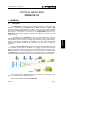
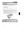
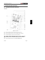
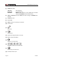
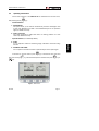
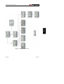
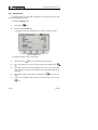
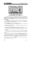
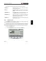
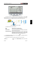
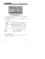
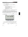
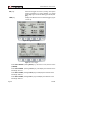
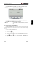
PROLITE-75
OPTICAL ANALYSER
99 Washington Street
Melrose, MA 02176
Phone 781-665-1400
Toll Free 1-800-517-8431
Visit us at www.TestEquipmentDepot.com
- 0 MI1652 -
USER’S MANUAL. PROLITE-75
O F
C O N T E N T S
1
GENERAL.................................................................................................................. 1
1.1 Description ....................................................................................................... 1
1.2 Specifications ................................................................................................... 2
2
SAFETY RULES........................................................................................................ 5
2.1 Generals........................................................................................................... 5
2.2 Descriptive Examples of Over-Voltage Categories .......................................... 6
3
INSTALLATION ......................................................................................................... 7
3.1 Power Supply ................................................................................................... 7
3.1.1
Charging the battery ............................................................................... 7
3.1.2
Recommendations using the battery ...................................................... 8
3.2 Installation and starting up. .............................................................................. 8
3.2.1
Adjusting contrast ................................................................................... 8
4
OPERATING INSTRUCTIONS.................................................................................. 9
4.1 Description of the controls and elements ......................................................... 9
4.2 Operating Instructions .................................................................................... 11
4.2.1
SETUP mode........................................................................................ 14
4.2.2
GPON METER Module......................................................................... 15
4.2.2.1 LOSSES Function ................................................................................ 17
4.2.2.2 ONT function ........................................................................................ 18
4.2.2.3 REFERENCE function.......................................................................... 20
4.2.2.4 THRESHOLD function.......................................................................... 21
4.2.2.5 LOGGER function................................................................................. 22
4.2.3
FAULT LOCATOR Module ................................................................... 25
4.3 Connecting Devices. ...................................................................................... 27
5
MAINTENANCE....................................................................................................... 29
5.1 Instructions for returning by mail .................................................................... 29
5.2 Method of maintenance.................................................................................. 29
5.2.1
Cleaning the cover................................................................................ 29
5.3 Components which user can not replace ....................................................... 29
5.3.1
Not replaceable fuses by user .............................................................. 29
English
T A B L E
USER’S MANUAL. PROLITE-75
USER’S MANUAL. PROLITE-75
OPTICAL ANALYSER
PROLITE-75
1 GENERAL
1.1
Description
In the design of the PROLITE-75, it was paid special attention to create a
practical and accurate instrument and, at the same time, easy to use. In this way, it has
been created a menu that allows accessing to the different operating modes directly,
through a simple system (ambidextrous) of softkeys, cursor keys and an alphanumeric
keypad. Once inside a function of the instrument, it is very easy to modify any
parameter.
All this makes the PROLITE-75 a great tool for installing and maintaining this type
of installations. Results will be displayed just plugging the fibre cable from the
distribution centre to the OLT input connector and the fibre cable from the user to the
ONT input connector. Then, pressing a key you will see the results on the screen. When
the PROLITE-75 is taken measures it acts as a pass-through instrument and extracts a
small percentage of the signal to measure, so the optic fibre service is not interrupted.
Figure 1.-
The instrument has an USB output connector to connect it to a computer. In this
way you can obtain reports or update firmware.
Next are explained functions of the PROLITE-75.
04-2009
Page 1
English
The PROLITE-75 is a tool to install, maintain and analyse general fiber optic
systems, and particularly FTTx-GPON systems. GPON networks use FTTx / PON
technology, delivering speed higher than 1 Gbps. In such networks, Upstream signals
are sent by the ONT (Optical Network Termination) in bursting mode, that is, it sends a
large amount of information in short time. The GPON METER module of the
PROLITE-75 has a function designed specifically to analyse the behaviour of these
signals over time.
USER’S MANUAL. PROLITE-75
The GPON METER performs filtered and individualized measurements for the
three wavelengths used in fibre (1490, 1550 nm for Downstream and 1310 nm for
Upstream) and displays them simultaneously on screen. It allows you to define and
store different threshold values.
The ONT shows graphically the Upstream signal over time. This function is
especially designed for GPON technology, in which the signal is transmitted in burst
mode.
The LOSSES function allows measuring insertion losses, defining a reference
value.
By the FAULT LOCATOR module you can generate a visible laser beam, and
allows you to change it in the form of continuous laser beam or pulses. Connecting the
laser output to the cable to check, you can find cuts or breaks, identify fibres, etc.
LOGGER function stores up to 100 measurements on the memory. In each data
acquisition is stored each wavelength measure and its related data. It can be reviewed
later, transferred to a PC and printed.
The PROLITE-75 can be expanded with two more modules: an OTDR module
and an channel analyser module.
The design of the PROLITE-75 is adapted for fieldwork: is compact and resistant
to adverse conditions. Backlight LCD of 5” inches and contrast dial provides an
excellent visibility for reading. Sizes of arrow keys and selection keys are adequate and
they are prepared for ambidextrous usage. An ergonomic silicone case, perfectly
adapted, protects the instrument from hitting or accidental falling and facilitates holding
it. Slider silicone covers keep input and output connectors from dust and other external
agents and they are built into the instrument. The Li-Ion battery is rechargeable and it
has a long operation time.
In conclusion, the PROLITE-75 is the ideal tool for any installation of optic fibre,
because is ergonomically designed, robust, easy to use and economical. It has all the
functions needed to make an installation and onward maintenance.
1.2
Specifications
GPON
Operating Wavelength Range
ONT Input
OLT Input
Insertion Loss
(ONT-OLT)
Polarization dependent loss
Isolation
1330 nm — 1490/1550 nm
1490 nm — 1550 nm
Page 2
1270 nm — 1350 nm.
1480 nm — 1500 nm & 1535 nm — 1565 nm.
<1,2 dB.
<0,2 dB.
>50 dB.
>50 dB.
04-2009
USER’S MANUAL. PROLITE-75
Connectors ONT, OLT
Internal Fibre optic:
Dinamic Range
ONT Input
OLT Input
SC/APC.
SMF-28e
From —30 dBm to 10 dBm.
From —40 dBm to 20 dBm.
FAULT LOCATOR
LASER type
Wavelength
Optical Power
Modulation
Connector
FP.
650 nm.
-2 dBm (monomode fibre / class 2).
1 Hz / 50 %.
Universal Receptacle 2,5 mm.
ALIMENTATION
7.4 V — 4,8 Ah.
Graphic indicator on screen.
11 h approx.
Disconnecting
after
not
using
10 minutes, configurable.
By fast internal charger.
22 W.
AL-103: 100 a 240 V AC / 50-60 Hz / 12 V DC.
Battery Charging
Consumption
Mains Adapter
for
ENVIRONMENTAL CONDITIONS
This equipment can be used on the following environmental conditions, on these
conditions the specifications could also be applied:
Altitude
Temperature range
Max. relative humidity
Up to 2.000 m.
From 5 °C to 40 °C.
80 % (up to 31 °C),
Decreasing lineally up to 50% at 40 °C.
MECHANICAL FEATURES
Dimensions
Weight
W. 160 x H. 230 x D. 50 mm.
1,4 kg. (battery and safety case included).
INCLUDED ACCESORIES
1x
1x
1x
1x
1x
1x
1x
AL-103
AA-103
0 FD0090
CA-05
CC-209
RM-027
PG4332
External DC power supply.
Feeder cable car.
Carrying case.
Mains cord.
Cordless Data Transfer USB to PC.
Software for PC PROLITE-75.
Transport suitcase.
RECOMMENDATIONS ABOUT THE PACKING
It is recommended to keep all the packing material in order to return the
instrument, if necessary, to the Technical service.
04-2009
Page 3
English
Li Ion Battery
Low Battery Indicator
Operating time
Auto Power Off
USER’S MANUAL. PROLITE-75
Page 4
04-2009
USER’S MANUAL. PROLITE-75
2 SAFETY RULES
2.1 Generals
*
The safety could not be assured if the instructions for use are not closely
followed.
*
The external DC charger is Class I equipment. For safety reasons plug it to a
supply line with the corresponding ground terminal.
Use the mains adapter in Over-Voltage Category II installations and Pollution
Degree 1 environments. It is for INDOOR USE.
*
When using some of the following accessories use only the specified ones to
ensure safety.
Power adapter
Car cigarette lighter adapter
*
Observe all specified ratings both of supply and measurement.
*
Use this instrument under the specified environmental conditions.
*
The user is not authorised to manipulate inside the instrument:
English
Mains cord
Any change on the equipment should be carried out by qualified personnel.
*
Follow the cleaning instructions described in the Maintenance paragraph.
04-2009
Page 5
USER’S MANUAL. PROLITE-75
*
Symbols related with safety:
DIRECT CURRENT
ALTERNATING CURRENT
DIRECT AND ALTERNATING
GROUND TERMINAL
ON (Supply)
OFF (Supply)
DOUBLE INSULATION
(Class II protection)
CAUTION
(Risk of electric shock)
PROTECTIVE CONDUCTOR
CAUTION REFER TO MANUAL
FRAME TERMINAL
FUSE
EQUIPOTENTIALITY
2.2
Specific Prescriptions
*
Use the FAULT LOCATOR output with caution. See description on the 4.1.
section.
*
*
Keep closed the cover of this output when not using it.
*
Bear in mind warning messages next to the output laser:
*
Do not manipulate inside the instrument, it could cause a dangerous laser
radiation.
The FAULT LOCATOR output emits visible laser light at 650 nm wavelength and
0 dBm power in a divergence beam of 0.15 rad.
2.3
Descriptive Examples of Over-Voltage Categories
Cat. I
Low voltage installations isolated from the mains.
Cat. II
Portable domestic installations.
Cat. III
Fixed domestic installations.
Cat. IV
Industrial installations.
Page 6
04-2009
USER’S MANUAL. PROLITE-75
3 INSTALLATION
3.1
Power Supply
The PROLITE-75 is a portable instrument powered by a Li-Ion battery. Before
performing any action, you must ensure that the battery is charged.
3.1.1 Charging the battery
The instrument is supplied with a mains adapter in order to power or charge the
battery.
1)
Stopped Instrument: When connecting the external power it will start a rapid
charging cycle, whose duration will depend on the battery status. It will take three
hours for a discharged battery. The charging indicator on the front panel (see
Figure 3.- [14]) will remain lit in amber colour during this period. At the end of
charging and in full charge, the indicator will be green.
2)
Instrument in operation: When connecting the charger, it will start a charging
process in a lower regime and therefore longer. At the end of charging and in full
charge, the indicator will change from amber to green colour.
Figure 2.- Mains adapter connected to the PROLITE-75.
PRECAUTION
04-2009
Before using the power adapter, make sure the adapter is
suitable for the mains voltage.
Page 7
English
There are two situations that can arise in the battery charging process:
USER’S MANUAL. PROLITE-75
3.1.2 Recommendations using the battery
If anticipating a long period of inactivity of the instrument, it is advisable to store it
with battery fully charged and at temperatures below 25 °C.
It is advisable in these cases doing every 3 months a cycle of charging /
discharging and a subsequent half charge (i.e. 50 %).
3.2
Installation and starting up.
The PROLITE-75 has been designed for using as a portable equipment.
A fully charged battery can power the device for more than 11 hours. The screen
) indicating the status of the battery charge. Four vertical
shows a battery icon (
black lines indicate the battery is full charged. As the battery decreases, the lines
) the battery should be recharged.
disappear. When shows a single line (
When starting up with a very low level battery, may be the PROLITE-75 could
start up, because of residual energy remaining at the battery, but the equipment will be
disconnected automatically BEFORE displaying on the screen the low level battery
indicator.
3.2.1 Adjusting contrast
LCD adjustment contrast is done via the dial ( see Figure 3.- [10] ) located at the
right side panel of the instrument.
By turning the dial is possible to adjust the screen contrast to get the best display
in any environmental condition. By turning anti-clockwise, the contrast decreases. By
turning clockwise, it increases. The new value of contrast is kept when the instrument
turns off.
Page 8
04-2009
USER’S MANUAL. PROLITE-75
4 OPERATING INSTRUCTIONS
4.1
Description of the controls and elements
English
Front panel
Figure 3.- Front panel.
[1]
SC-APC (Female) connector for ONT input signal (1310 nm).
[2]
SC-APC (Female) connector for OLT input signal (1490 / 1550 nm).
[3]
Universal receptacle (2,5 mm) for laser output (650 nm).
CAUTION: VISIBLE LASER BEAM (650 nm). DO NOT STARE INTO
THE BEAM. CLASS 2 CATEGORIE LASER FOR THE VFL MODULE.
[4]
SC-APC (Female) connector for the additional OTDR module.
04-2009
Page 9
USER’S MANUAL. PROLITE-75
[5]
GPON Status LEDs:
LEFT LED:
ONT (Upstream).
RIGHT LED:
OLT (Downstream).
COLOURS:
GREEN (within threshold values), RED (below threshold
values) and ORANGE (above threshold values).
[6]
FAULT LOCATOR Status LED: RED (laser beam working) and GREEN (laser
disabled).
[7]
OTDR Status LED.
[8]
Backlit LCD.
[9]
USB connector for connecting to a computer.
[10] Contrast Dial.
[11]
Arrow keys.
[12]
Selection key.
[13] Alphanumeric keypad made up of 12 keys.
[14] Battery charge LED indicator.
[15]
Starting up / Turning off key.
[16]
SOFTKEYS, made up of 5 function keys.
[17]
Shortcut key to the main menu.
[18] DC Adaptor Power Input.
Page 10
04-2009
USER’S MANUAL. PROLITE-75
4.2
Operating Instructions
The two main functions of the PROLITE-75 are accessible from the main menu,
[17]:
after pressing the key
-
Installed Modules
1.- GPON METER:
This option allows you to measure simultaneously the three wavelengths used
in fibre optic distribution and take a more detailed analysis of the Upstream
signal (for details see 4.2.2).
2.- FAULT LOCATOR:
This option generates a visible laser beam, for locating problems in a fibre
network (for details see 4.2.3).
Optional Modules (not installed by default).
3.- OTDR:
It is an expansion module for measuring length, attenuation and events along
the fibre.
4.- CHANNEL ANALYSER:
It is an expansion module that makes a spectral analysis of the optical signal.
To access any of these menus, press
then press the key
[17] to access the main menu and
[11] until the desired option is shaded. Then press
[17] or
[12].
Figure 4.- Main Screen.
04-2009
Page 11
English
-
USER’S MANUAL. PROLITE-75
At the bottom of the screen appears the following options:
LIGHT OFF / ON [F1]:
Turns ON / OFF the backlight.
SETUP [F5]:
This menu allows you to edit basic characteristics of the
instrument such as time, date and language among
others (more details on 4.2.1).
After pressing the shortcut key
menu, regardless the submenu where it is.
Page 12
[17], the system comes back to the main
04-2009
English
USER’S MANUAL. PROLITE-75
Figure 5.- General view of the menu tree.
04-2009
Page 13
USER’S MANUAL. PROLITE-75
4.2.1 SETUP mode
This menu allows you to edit basic parameters of the instrument such as time,
date and language among others.
To access the SETUP mode:
[17].
1.-
Press the key
2.-
Press the soft key SETUP [F5].
It will appear a screen with parameters of the system to configure (Fig. 6).
Figure 6.- SETUP screen.
To change the status or value of a parameter:
[11] to move the cursor along the menu.
1.-
Use the arrow keys
2.-
Go to the parameter you want to change and press the selection key
[12].
3.-
The cursor will move next to the parameter value. Now you can change that
value, using the arrow keys or the alphanumeric keypad (depending on the
parameter).
4.-
After making changes press again the selection key
values.
5.-
To exit the Configuration Mode and return to the main menu, press the key
[12] to save new
[17].
Page 14
04-2009
USER’S MANUAL. PROLITE-75
Editable parameters are next:
a) HOUR
It indicates the current time. Enter hours and minutes by the alphanumeric keypad.
To enter the symbol “:” between hours and minutes, you should use the key
which is in the alphanumeric keypad.
,
b) DATE
It indicates the current date in European notation (dd-mm-yy). Enter the day, month
and year by the alphanumeric keypad. To enter the hyphen symbol between
which is in the alphanumeric keypad.
numbers, press the key
c) LANGUAGE
The language selected will be used on menus and screen. Use the arrow keys to
move among available languages (Spanish, English, German and Portuguese).
e) AUTO POWER OFF
This parameter allows you to activate (ON) or disable (OFF) the auto power off
function. When this feature is active, the instrument will automatically disconnect
from power supply after ten minutes without pressing any key.
At the bottom of the screen it appears the next information (read-only):
-
BATTERY:
Indicates the battery charge (in voltage).
-
FIRMWARE:
Indicates the firmware version of the instrument.
-
SERIAL NUMBER:
It is an unique identifier number for the instrument.
4.2.2 GPON METER Module
The GPON METER module performs filtered and individualized measurements
for the three wavelengths used in optic fibre for signal transmission (1490, 1550 nm for
Downstream and 1310 nm for Upstream) and displays them simultaneously on screen.
To access the GPON module:
[17].
1.-
Press the key
2.-
Press the arrow keys until the GPON METER option is shaded.
3.-
Press the key
screen (Figure 7).
04-2009
[17] or
[12]. It appears the GPON METER main
Page 15
English
d) BEEP
This parameter enables (ON) or disables (OFF) the acoustic indicator that beeps
when pressing any key.
USER’S MANUAL. PROLITE-75
Figure 7.- GPON METER main screen in ABSOLUTE mode.
The screen shows a box chart divided into three equal parts. Each one shows the
power level for a given wavelength, in a graphical and numerical way. At the bottom it
identifies what wavelength belongs to each division. Left division corresponds to the
wavelength 1310 nm of UPSTREAM and the other two (1490 and 1550 nm) to the
DOWNSTREAM.
The ABSOLUTE measurement mode is the measurement of the absolute value
of the signal strength in dBm (dB referred to 1 mW), as opposed to LOSSES mode
representing the measure of the signal power in dB.
The AVERAGE power of the Upstream signal (1310 nm) is represented
graphically superimposed on the peak value in opaque texture.
Two marks in each division (--- x ---) represent the maximum and minimum
threshold values for each wavelength.
The screen displays status messages depending on the power level in relation to
the maximum and minimum threshold values (see figure 7). They are next:
When the power is below the minimum threshold value it will appear the status
message LOW.
When the power is within the threshold values, the status message will be GOOD.
When the power is above the maximum threshold value, the status message will
be HIGH.
At the bottom of the screen it is displayed the THRESHOLD GROUP to which
belongs the threshold values shown on screen. It shows the given name of the
threshold group using currently. Threshold values can be grouped and saved in the
memory of the instrument. Then, you can select the one more suited you want. If this
field is shaded, pressing the arrow keys
threshold values saved on the memory.
Page 16
[11] you can move among the groups of
04-2009
USER’S MANUAL. PROLITE-75
At the bottom of the screen, softkeys provide access to the next options:
LOSSES [F1]:
Pressing this softkey you can measure the insertion
losses (see section 4.2.2.1).
ONT [F2]:
Pressing this softkey you will get into the function to
measure Upstream signal over time (see section
4.2.2.2).
REFERENCE [F3]:
This function allows you to enter the reference values
for LOSSES measurement (see section 4.2.2.3).
THRESHOLD [F4]:
Using this function you can define and save some
threshold values in groups. Later they can be used for a
measurement (see section 4.2.2.4).
LOGGER [F5]:
Pressing this key you can save measures taken at the
time (see section 4.2.2.5).
LOSSES Function
The LOSSES function calculates the insertion loss of each wavelength with
respect to some reference values acquired by the user.
The Insertion Loss of a line is the ratio of the power received at the end of the line
to the power transmitted into the line. The loss of signal power is due to the different
elements that are in the optical fibre system, such as connectors, splices and couplers.
To access the LOSSES module:
1.-
From the GPON METER function press the softkey LOSSES [F1].
Figure 8.- LOSSES screen.
04-2009
Page 17
English
4.2.2.1
USER’S MANUAL. PROLITE-75
The screen shows (Figure 8.-) the loss or gain of the power in dB units, for each
of the wavelengths, in the form of a horizontal bar graph and in numerical format.
The central point "0" of the graph represents the reference level acquired. From
this reference level, the signal power can grow or decrease. Typically, in a signal that
goes to the OLT (Downstream: 1490/1550) losses may grow, but when goes to the
ONT (Upstream: 1310) may decrease as it approaches to the emission center.
The bar graph can represent gain/losses up to ± 40 dB with regard to the
reference level. The end of each bar graph will show an arrow when exceeding this
value. In numeric format will show the real value.
At the bottom of the screen, softkeys provide access to the next options:
METER [F1]:
Pressing this softkey returns to the GPON METER
function (see paragraph 4.2.2).
ONT [F2]:
Pressing this softkey you will get into the function to
measure Upstream signal over time (see paragraph
4.2.2.2).
REFERENCE [F3]:
This function allows you to enter the reference values
for measuring LOSSES (see paragraph 4.2.2.3).
THRESHOLD [F4]:
Using this function you can define and save some
threshold values in groups. Later they can be used for a
measurement (see paragraph 4.2.2.4).
LOGGER [F5]:
Pressing this key you can save measures taken at the
time (see paragraph 4.2.2.5).
4.2.2.2
ONT function
The function ONT TIME ANALYSER performs the characterization of a ONT
signal. In this way, allows displaying the pulses activity of the Upstream signal
(1310 nm) over time. Also allows time scale to be change (resolution). This analyser is
specially designed to catch BURST signals, that is, when it is sent a lot of information in
a very short time.
To access the ONT function:
1.-
Page 18
From the GPON METER function press the softkey ONT [F2].
04-2009
USER’S MANUAL. PROLITE-75
Figure 9.- ONT Analyser.
English
To use this function, the meter has to be connected directly to a single ONT
terminal (see fig. 10.-). If you connect the meter to an intermediate point in the network,
it can take part more than one ONT and then the analysis would not be correct.
Figure 10.- Direct Connection to an ONT.
The measures shown on the screen are:
PK:
Peak power of the Upstream signal.
AVG:
Average power of the Upstream signal.
DUTY CYCLE:
Cycle of work defined as the percentage ratio between
the pulse duration and period.
EXTINCTION RATIO: Ratio of two optical power levels (in dB) of a digital signal
generated by an optical source, where P1 is the optical
power level number 1 when the light is "on" and P2 is the
optical power level number 2 when the light is "off."
To change the time scale, press the cursor keys
from 50 microseconds to 100 ms.
[11]. Available values are
At the bottom of the screen, softkeys provide access to the next option:
BACK [F1]:
04-2009
Returns to the GPON METER function (see section
4.2.2).
Page 19
USER’S MANUAL. PROLITE-75
4.2.2.3
REFERENCE function
REFERENCE function allows you to define the reference values that will be used
for LOSSES measurement (see Figure 11.-).
To access the REFERENCE function:
1.-
From the GPON METER function press the soft key REFERENCE [F3].
Figure 11.- REFERENCE function.
To take a reference value, press the softkey corresponding to the wavelength at
which you want to capture the new value. By doing this, the system will take as a
reference value the power given on the column “POWER”. Once you have the captured
value, pressing
[12] you confirm and store it on the device’s memory.
Data shown on the screen is next:
WAVELENGHT:
It displays the wavelength and the data when the level of
reference was taken.
POWER:
Displays real-time absolute power for each wavelength.
REFERENCE:
Displays the current reference power (in dBm). To
upgrade the power reference, press the softkey
corresponding to the wavelength at which you desire a
new reference value.
At the bottom of the screen, soft keys provide access to the next options:
BACK [F1]:
It returns to the GPON METER screen (see section
4.2.2).
1310 nm [F3]:
It captures the reference power at 1310 nm. Once
captured, confirm the value pressing the key
Page 20
[12].
04-2009
USER’S MANUAL. PROLITE-75
1490 nm [F4]:
It captures the reference power at 1490 nm. Once
[12].
captured, confirm the value pressing the key
1550 nm [F5]:
It captures the reference power at 1550 nm. Once
[12].
captured, confirm the value pressing the key
4.2.2.4
THRESHOLD function
The THRESHOLD function allows you to edit the threshold values that will be
used during measurement.
To access the THRESHOLD function:
1.-
From the GPON METER function press the soft key THRESHOLD [F4].
Once defined, they appear in the graph at the GPON METER function, in the
shape of a line with an “x” in the middle (--x--) (Fig.- 7.-).
Status level defined by the threshold values are:
-
Power level above the maximum threshold value is equal to HIGH.
-
Power level between the maximum and minimum threshold value is equal to
GOOD.
-
Power level below the minimum threshold value is equal to LOW.
In addition, LEDs associated with the ONT and OLT signals [5] change its colour
depending on the power signal level.
-
If level is LOW, the colour of the LED is RED.
-
If the level is MEDIUM, the colour of the LED is GREEN.
-
If the level is HIGH, the colour of the LED is ORANGE.
04-2009
Page 21
English
The THRESHOLD function allows you to define a minimum threshold value
(LOW) and maximum (HIGH) of acceptability for each wavelength (Fig. 12.-).
USER’S MANUAL. PROLITE-75
Figure 12.- THRESHOLD function.
To move between editable fields you should press the softkey PREV [F4]
(previous field) or NEXT [F5] (next field).
Once on the field, to edit a value you should use arrow keys
alphanumeric keypad [13].
[11] or the
Fields displayed on the screen are:
THRESHOLD:
Its a numeric value that identifies a set of threshold values.
NAME:
It is the name that defines a set of threshold values.
WAVELENGHT:
It indicates the wavelength to which will be applied the
threshold values shown on the screen.
LOW:
It defines the minimum threshold for a given wavelength.
HIGH:
It defines the maximum threshold for a given wavelength.
At the bottom of the screen, the soft keys provide access to the next options:
BACK [F1]:
It returns to the GPON METER screen (see 4.2.2).
PREV [F4]:
It goes to the previous editable field.
NEXT [F5]:
It goes to the next editable field.
4.2.2.5
LOGGER function
LOGGER function performs data acquisitions and stores them on the instrument.
Later you can view or print those data.
Page 22
04-2009
USER’S MANUAL. PROLITE-75
To access the LOGGER function:
1.-
From the GPON METER function press the soft key LOGGER [F5].
The data stored in a logger is:
-
Power at 1310, 1490 and 1550 nm (dB).
Status Message regarding power level (LOW, GOOD, HIGH).
Date and Time of acquisition.
Average level power for each wavelengths.
Relative level power for each wavelengths.
Threshold group used.
The LOGGER main screen shows a list with all loggers stored until now. On the
left side of the logger line it indicates the logger number, followed by date and time of
acquisition. When saving a logger, system assigns automatically a registration number
to the new file, which is correlated to the numbering in the list of loggers. It can also
reuse a number from a logger that was removed.
To select a logger, you should press the arrow keys
points at the desired logger.
[11] until the cursor
Figure 13.- List of stored loggers.
If there are not loggers stored, it is displayed the message “EMPTY LOGGER”.
At the bottom of the screen, the soft keys provide access to the next options:
BACK [F1]:
04-2009
Returns to the GPON METER screen (see section
4.2.2).
Page 23
English
The PROLITE-75 allows you to store up to 100 acquisitions or loggers. These
measures are stored on its memory for later view, printing or transfer to a PC.
USER’S MANUAL. PROLITE-75
DEL [F2]:
Removes the logger the cursor is pointing. The system
requires confirmation. To confirm deleting, you should
press [F4]. To get out without deleting you should press
[F5].
VIEW [F3]:
Displays the data stored in the selected logger (Figure
14 and 15).
Figure 14.- Logger General Screen.
Figure 15.- 1310 nm Signal.
From VIEW LOGGER, pressing BACK [F1] it will return to the previous screen
(LOGGER).
From VIEW LOGGER, pressing 1310 nm [F2] it will display the measures of the
wavelength 1310 nm.
From VIEW LOGGER, pressing 1490 nm [F3] it will display the measures of the
wavelength 1490 nm.
From VIEW LOGGER, pressing 1550 nm [F4] it will display the measures of the
wavelength 1550 nm.
Page 24
04-2009
USER’S MANUAL. PROLITE-75
From VIEW LOGGER, pressing PRINT [F5] the logger print directly to a printer.
STORE [F4]:
Stores all measures in a logger file.
Figure 16.- Storing a Logger.
From STORE, pressing QUIT [F5] Storage is cancelled.
PRINT [F5]:
It prints the data from the logger selected (see section
4.3).
4.2.3 VISUAL FAULT LOCATOR Module
The FAULT LOCATOR module emits a visible laser beam. Connecting the output
of the laser instrument to the cable to check, you can find cuts or breakings, identify
fibers, etc.
To access the FAULT LOCATOR module:
[17].
1.-
Press the key
2.-
Press the arrow keys
3.-
Press
[17] or
(Figure 17 and 18).
04-2009
[11] until the option FAULT LOCATOR is shaded.
[12]. It appears the FAULT LOCATOR screen
Page 25
English
From STORE, pressing SAVE [F4] It generates a logger where data is stored.
USER’S MANUAL. PROLITE-75
Figure 17.- FAULT LOCATOR module (NOT ACTIVE).
Figure 18.- FAULT LOCATOR module (ACTIVE).
On the screen appears features of the laser:
-
“Laser status“: Active or Not Active.
-
“Modulation“: Active (ON) or not (OFF) laser pulses.
-
“Optical Power”: Power consumption of the laser.
-
“Wavelength”: Wavelength of the laser.
At the bottom of the screen, softkeys provide access to the next options:
BACK [F1]:
Returns to the main screen.
MOD ON / OFF [F4]:
Actives / Disables the laser modulation at 1 Hz.
OUT OFF / ON [F5]:
Actives / Disables the laser beam.
Page 26
04-2009
USER’S MANUAL. PROLITE-75
4.3 Connecting Devices.
The instrument allows connecting a personal computer to transfer data, via USB
cable.
1)
To make the connection between the instrument and the computer, first you
should disconnect both from the mains.
2)
Connect the cable end to the USB connector [9] at PROLITE-75 and the
other end into the USB port of the computer.
If there is any error during transmission, a message show up on screen to warn
about the error.
The control software manages the data downloaded from the instrument:
1)
LOGGER: Edits and saves on the computer loggers from the instrument.
2)
UPGRADE: Upgrades to the latest firmware version.
English
For more details consult the software user’s manual.
04-2009
Page 27
USER’S MANUAL. PROLITE-75
Page 28
04-2009
USER’S MANUAL. PROLITE-75
5 MAINTENANCE
This part of the manual describes the maintenance procedures and the location of
faults.
5.1 Instructions for returning by mail
Instruments returned for repair or calibration, either within or outwit the guarantee
period, should be forwarded with the following information: Name of the Company,
name of the contact person, address, telephone number, receipt (in the case of
coverage under guarantee) and a description of the problem or the service required.
5.2 Method of maintenance
5.2.1 Cleaning the cover.
CAUTION
Do not use scented hydrocarbons or chlorized solvents. Such products may attack the
plastics used in the construction of the cover.
The cover should be cleaned by means of a light solution of detergent and water
applied with a soft cloth. Dry thoroughly before using the system again.
CAUTION
To clean the contacts, use a dry cloth. Do not use a wet or damp cloth.
CAUTION
Do not use for the cleaning of the front panel and particularly the viewfinders, alcohol or
its derivatives, these products can attack the mechanical properties of the materials and
diminish their useful time of life.
5.3 Components which user can not replace
5.3.1 Not replaceable fuses by user
F001 y F002:
04-2009
FUS
7A
T 125 V
Page 29
English
The method of maintenance to be carried out by the user consists of cleaning the
cover and changing the battery. All other operations should be carried out by authorised
agents or by personnel qualified in the servicing of instruments.