1
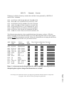
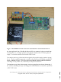
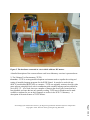
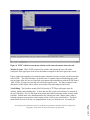
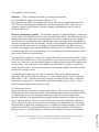
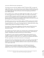
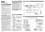
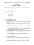
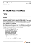
Session 3432
An ECE Freshman Microcontroller Course at the University of Maine
Dan Beenfeldt, Eric Beenfeldt, John Field, Edward Williams
University of Maine
Abstract
This paper describes ECE 171 Microcomputer Architecture and Applications, a 4-credit lab
course based on Motorola’s M68HC11 microcontroller. The course introduces computer
architecture, assembly language programming, and applications of microcontrollers to freshman
electrical and computer engineers as well as other students, primarily students majoring in
computer science and engineering physics.
I. Introduction
For over twelve years the ECE Department has required two semester-long courses in the
freshman curriculum to introduce its majors to their discipline. Initially, both of these courses
were wholly technical where the first course dealt with digital logic and the other with assembly
1
language programming. In the early 1990’s the first course , ECE 101, was restructured to
provide a general introduction to electrical and computer engineering, including modules aimed
at helping students make the transition from high school to college. Technical topics include
resistive circuits, RC circuits, the 555 timer, combinational logic, Karnaugh maps, sequential
logic, DC motors and PWM control. These topics give the technical background for
understanding the operation of a remote control vehicle that they build. Our students also learn
the hands-on skills of soldering, wire wrapping, reading schematics, and using basic lab
equipment for trouble shooting. This portion gives students an appreciation for the importance
of a modular approach to design and test. Finally, we introduce Mathcad 2 as a tool for
mathematical analysis including graphing and analysis of experimental data. Since some of our
students have no background in programming we also introduce fundamental programming
constructs like if-otherwise, for-loops, and while-loops using the programming capability of the
Professional version of Mathcad. Thus, by the spring semester when they take the second
course, ECE 171, our students have a good background in digital circuits and a cursory
introduction to fundamental programming constructs.
Also in the spring semester, our students take an introductory C++ course from the computer
science department. This dovetails nicely with a segment of ECE 171 where we show how C
statements can be implemented in 68HC11 assembly code.
Page 7.166.1
Proceedings of the 2002 American Society for Engineering Education Annual Conference & Exposition
Copyright Ó 2002, American Society for Engineering Education
ECE 171 focuses on learning how to program Motorola’s M68HC11 3 microcontroller to
perform simple tasks. We use a custom software development tool to develop assembly
language programs that execute on a Motorola M68HC11 EVBU 4 evaluation board. This tool
is designed to work with the EVBU’s monitor program, BUFFALO. We also developed a
custom interface board that allows for interesting and challenging exercises. The remainder of
the paper describes these areas as well as how the course is administered. The custom software
tool is presented in detail, in part because of its usefulness with the EVBU board, and in part
because it is useful with any 68HC11-based system that uses BUFFALO as a monitor program.
II. Course Administration
Two faculty members (1-FTE) are assigned to the course, which normally has about 80-90
students. Also, two to three selected sophomores ar e employed to assist in lab. This helps
these top students become associated with the Department and gives them a chance to reinforce
concepts learned the previous year. It is also a great opportunity for the first -year students to
relate to the peer teachers, particularly since the peer teachers are only one year ahead of them.
The class meets Monday, Wednesday, and Friday mornings for 50 minutes. Additionally, there
is a weekly 3-hour lab (four sections are offered with 20-24 students in each). We try to use
very little straight lecturing in the lecture classes. We agree with Felder 5 that lectures do not
work as well as we may have once hoped or expected. So frequently, instead of long lectures,
we briefly present a concept, then break the students into two to four person groups, and use inclass collaborative learning activities to check on understanding. This has proven to be an
excellent way to maintain interest and to let the students know where they need to put in some
work if they don’t feel comfortable with the material. An example of an in-class exercise
dealing with recognizing addressing modes and instruction tracing is presented in Figure 1.
To help maintain communications and to make information available electronically, we use a
computer conferencing system called FirstClass. In addition to providing a general email
service it allows the creation of a “conference” for an individual course. A conference is
essentially a bulletin board, e.g., allowing ECE 101 students and faculty to post comments,
questions, and answers for all to share. It also allows documents to be attached to messages so
that they can be downloaded by all. We make particular use of this latter feature to distribute
homework and laboratory assignments. Educational objectives for ECE 171 are described next.
III. Educational Objectives
Listed below are the major educational objectives for ECE 171.
The student will be able to:
1. Express signed and unsigned numbers in hexadecimal, decimal, and binary.
2. Interpret and use data correctly depending on the situation.
Page 7.166.2
Proceedings of the 2002 American Society for Engineering Education Annual Conference & Exposition
Copyright Ó 2002, American Society for Engineering Education
ECE 171
Classwork
Exercise
Following is a display of memory contents that could have been generated by a BUFFALO
md 0150 01cf command.
0150
0160
0170
0180
0190
01A0
01B0
01C0
00 45 F4 10 54 FC D9 A0 B9 21 4F 22 84 8B 4C FF
D9 A0 B9 21 4F 22 84 8B 4C FF 00 45 F4 10 54 FC
00 45 F4 B9 21 4F 22 84 8B 4C FF 10 54 FC D9 A0
A0 4F 22 84 8B 4C FF B9 21 00 45 F4 10 54 FC D9
00 45 F4 B9 FC D9 01 71 4F 22 84 8B 4C FF 10 54
84 8B 4C FF 45 F4 10 54 00 21 4F FC D9 A0 B9 22
00 45 F4 10 54 FC D9 A0 4F 22 84 8B 4C FF B9 21
84 8B 4C 10 54 FC D9 A0 A0 22 4F 22 84 8B 4C CB
The following instructions have been assembled and stored in memory as shown. Fill in the
blanks to the right of each instruction below to give the addressing mode used as well as register
contents AFTER the instruction is executed. Assume the instructions are accessing the data above
and the PC is initialized to 0100. Give your answers in hex.
Addr Machine
Code
0100 86 54
0102 F6 01 60
0105 FC 01 60
0108 FE 01 60
010B CE 01 80
010D A6 04
010D 08
010E EE 05
0110 3A
0111 8F
0112 CE 01 C0
0115 6C 00
0117 A6 00
Source
Addr
Instruction
Mode
LDAA #$54
LDAB $0160
LDD $0160
LDX $0160
LDX #$0180
LDAA 4,X
INX
LDX 5,X
ABX
XGDX
LDX #$01C0
INC 0,X
LDAA 0,X
Reg. Contents (After Instr. Executes)
A
B
X
Figure 1. A classroom exercise that gives practice with recognizing addressing modes and
interpreting how registers change when instructions are executed.
Page 7.166.3
Proceedings of the 2002 American Society for Engineering Education Annual Conference & Exposition
Copyright Ó 2002, American Society for Engineering Education
3.
4.
5.
6.
7.
8.
9.
List the 68HC11 addressing modes and describe a situation where each is preferred.
List the basic groups of 68HC11 instructions
Describe the basic 68HC11 hardware modules and how they work.
List the registers in the programming model of the 68HC11 and explain how each is used.
Correctly document assembly language programs.
Design, test, and debug assembly language programs to perform a given function.
Describe and be able to use an editor, assembler, loader, simulator, and related debugging
tools.
10. Describe how a stack is used by interrupts and subroutines and how it can be used to pass
data.
11. Describe how a statement in C could be implemented in 68HC11 assembler code.
These objectives overlap. For example, objectives 1. and 2. are somewhat related in that 2.
requires that the student determine what data represents; e.g., is it a signed or unsigned number,
an ASCII character, instruction op-code, instruction operand, or a hardware state? Similarly,
objectives 1., 2., 8., and 9 are involved in a program that adds two 8-bit numbers and
determines if the 8-bit result is correct.
Each of these major objectives has sub-objectives. For example, under objective 5. dealing with
hardware modules, we have a sub-objective that the student will be able to describe what
happens during each cycle as a single instruction executes. This means that for each cycle the
student should be able to give the states of the data and address busses, the program counter,
R/W-bar, and any affected registers or memory locations. Another sub-objective states that the
student will be able to describe the 68HC11’s timers, input capture registers, and serial I/O
register.
IV. Laboratory Hardware
We use the M68HC11 EVBU board with a custom interface board designed at UMaine. A
typical setup is shown in Figure 2. It consists of a 12V battery (rechargeable), an EVBU board,
an interface board and a PC connected to the EVBU via a serial cable. The PC communicates
with the EVBU board via a custom software tool. This tool, called The Ultimate Test
Environment, (TUTE) was developed for UMaine by one of the authors (DB) and is described
more fully in the next section.
The interface board has 4 push-button switches and 6 LEDs. The switches are connected to the
least significant four bits of the 68HC11’s PORT C. Three of the switches are also connected
to the least significant three bits of Port A. The four LEDs above the switches are connected to
Page 7.166.4
Proceedings of the 2002 American Society for Engineering Education Annual Conference & Exposition
Copyright Ó 2002, American Society for Engineering Education
Figure 2. The M68HC11 EVBU board and custom interface board used in ECE 171.
the least significant 4-bits of Port B while the top LEDs are connected to the most significant
two bits of Port A. A voltage regulator on the interface board uses the 12V battery input to
supply 5V to both the interface board and the EVBU board.
The connector at the top of the board allows signals to be passed through to another external
device. We have used this connection to control a vehicle with two individually controlled DC
motors as shown in Figure 3. This is the same vehicle that the students controlled with hardwired logic circuitry in ECE 101, which they took the previous semester.
The hardware set-up allows for interesting exercises ranging from the software debouncing of
the switches to handling interrupts and using pulse width modulation to control the speed of the
vehicle’s DC motors.
Page 7.166.5
Proceedings of the 2002 American Society for Engineering Education Annual Conference & Exposition
Copyright Ó 2002, American Society for Engineering Education
Figure 3. The hardware connected to a test vehicle with two DC motors.
A detailed description of the custom software used in our laboratory exercises is presented next.
V. The Ultimate Test Environment, (TUTE)
Overview - TUTE is an integrated development environment used to expedite the writing and
testing of assembly language programs for the EVBU Board. It can also be used with any
68HC11 board that has BUFFALO as a monitor. TUTE was originally written to develop video
game software using high level code in combination with assembly language and was altered for
use in ECE 171. As a result, there are a number of features that are not used, some that have
been disabled, and some that are only partially working. TUTE runs in Windows and is made
available to students for use on their computers as well as in the ECE 171 laboratory. A
description of the main features of TUTE follows.
Page 7.166.6
Proceedings of the 2002 American Society for Engineering Education Annual Conference & Exposition
Copyright Ó 2002, American Society for Engineering Education
Figure 4. TUTE’s initial screen shown with the serial connection menu items selected.
Window Layout - When TUTE is opened, the window will present the user with a blue
workspace in the upper part of the screen and white workspace in the lower part of the screen.
Figure 4 shows the opening screen with the menu selections necessary to open a serial connection
to the EVBU. The white workspace is divided into 12 separate pages selected using tabs at the
top; the pages allow the user to control the environment and communicate with the EVBU board.
Only 4 of the 12 pages are used and each will be discussed in turn. The blue workspace is the
edit portion of the system with a yellow cursor and red line indicating the end of text.
Text Editing - The first three menus (File Edit Search) of TUTE provide menu items for
creating, editing, and searching files. If more than one file is open, each will have its own tab at
the top of the page. The Cut and Paste menu items under Edit work using stream or block mode
selection. Stream mode is the standard method for selecting text with a mouse where what is
selected represents some portion of the stream or flow of text as one would read it. The block
mode allows the user to cut out a rectangular block of any size from the text. It is handy for
Page 7.166.7
Proceedings of the 2002 American Society for Engineering Education Annual Conference & Exposition
Copyright Ó 2002, American Society for Engineering Education
moving comments around in assembly language code.
One feature of the editor that enhances its capability as an assembly language development system
is the color-coding of labels, instructions, numbers, and comments. For this feature to work, the
file must first be saved with a .asm extension. When an assembly language statement is entered,
labels and instruction operands are automatically shown in the color yellow. Instructions are
always shown in white, numbers appear in light blue and comments are an off white color. This
is very helpful to a new programmer who may not be familiar with the complete instruction set.
If the instruction does not come out in white, the instruction has been entered incorrectly. In
addition to coloring the instruction white, the editor will display a synopsis of the instruction at
the bottom of the page showing the meaning of the instruction, all the addressing modes, and how
the condition code register can be affected by this instruction.
Assembling Code - Once the code has been written, selecting the menu item Assemble under the
RUN menu (RUN à Assemble) will assemble it. If there are no errors in the syntax of the code,
a small blue dot will appear in the far left-hand column of each line of the code containing an
instruction. If blue dots don’t appear, or if they stop in the middle of the program, there is
something wrong. The assembler will stop at the incorrect statement and highlight it.
Some unusual syntax errors are not detected, for example, the statement:
BHI #NEXT
will not be flagged as incorrect. Instead the assembler assumes the immediate symbol (#) should
not be there and makes correct machine code accordingly. Students are warned, however, that if
these errors are found in a submitted program the grader will not be so forgiving!
TUTE’s assembler generates a listing of the code and a table of labels. These can be found under
the Listing tab of the white pages. An S-record file, containing the program’s machine code and
corresponding addresses, is also generated.
Connecting to the EVBU - Communications between TUTE and the EVBU board take place
over an RS232 serial communication channel. The connection process of selecting Runà
HC11à Buffaloà Connectà Comm1 is shown in Figure 4. The connection is then verified by
clicking the Comm tab in the white pages and pressing the enter key. The EVBU will respond by
sending a message to the Comm screen (usually a prompt, >).
Loading a Program - After assembling a program and opening a link to the EVBU, the next step
is to load the machine code generated by the assembler into the EVBU’s RAM. This is
accomplished by selecting the Runà Load menu options which cause TUTE to send an S-record
file to the EVBU .
Page 7.166.8
Proceedings of the 2002 American Society for Engineering Education Annual Conference & Exposition
Copyright Ó 2002, American Society for Engineering Education
After the load operation, the cursor on the edit portion of the screen will move to the first
instruction of the assembly language program and a blue box will be drawn around the instruction.
This means the that TUTE is ready to tell the EVBU board to start at this instruction. If it is
desired to begin at some other point in the program, move the cursor to that point, select the
RunàSet Execution Point menu item and the blue box will move to that point.
Program Execution - There are four ways to begin executing a program, and each differs in how
the code will stop. Programs generally do not work correctly the first time and each different way
of stopping the program will have an advantage in the debugging process. Next, each technique
for executing a program is discussed preceded by the menu steps needed to invoke it.
RunàStep - This is the simplest method but is too tedious for many situations. Selecting this
menu item will run one instruction at a time. The blue box will move one instruction and stop.
This is a good way to run code in the beginning to see just how it works. This method makes use
of the BUFFALO’s Trace command.
RunàRun - This method is best to use after the program has been shown to work. This starts
running the code at the present location of the program counter (or cursor location) and runs until
the EVBU is reset or control returns to the EVBU (for example with an SWI instruction). This
method makes use of the BUFFALO’s Go command.
RunàRun to Caret - This menu item allows moving the cursor to an instruction ahead of the
present instruction and then running to that point. “Ahead” means that the line chosen must be
one that will be executed when the program runs from the present instruction. This method
makes use of the BUFFALO’s StopAt command.
Runà Toggle Breakpoint - This is the most sophisticated method and is most useful in
debugging programs that involve loops that are executed multiple times. A breakpoint is an
instruction at which the program always stops (before executing). Once a breakpoint is set, the
EVBU will always stop at this point and allow registers and memory to be examined. A
breakpoint is set by moving the cursor to the appropriate instruction and then selecting the Toggle
Breakpoint menu item. Once selected as a breakpoint, the instruction will turn red to indicate that
it is a breakpoint. To clear the breakpoint, the cursor is set on the instruction and Toggle
Breakpoint is selected again. Up to 4 breakpoints may be set simultaneously.
Displaying Registers and Memory - Once the program has stopped, it is useful to examine
registers and memory locations containing program data. Clicking the Debug tab of the white
pages will open a Debug window that allows selection of what is displayed each time execution is
stopped. Memory locations that have been defined with FCB or RMB assembler directives can
also be displayed. Information can be displayed in binary, decimal, or hexadecimal.
Tute’s simulator allows many aspects of a program to be checked without using an EVBU board.
Page 7.166.9
Proceedings of the 2002 American Society for Engineering Education Annual Conference & Exposition
Copyright Ó 2002, American Society for Engineering Education
This capability is discussed next.
Simulator - TUTE’s simulator is invoked by selecting the menu items,
Run àTARGETà Options à Simulator (Release v1.1a)
Now, instead of the EVBU, the simulator will run any code that is assembled and loaded. All
of TUTE’s Run menu items are available and work just as described above. Thus, once the
simulator is started, all the features of running, stopping, and displaying code will work as
with the EVBU board.
Hardware Simulation Capability – The simulator supports a “Lights and Buttons” window that
is very similar to the LEDs and switches on our custom interface board. The differences are in the
address locations and what signal is returned (high or low) when a switch is pressed. Initially it
was felt this was a good thing because it allowed us to assign a program for the actual hardware
and then a subsequent one for the simulator. We felt a well-documented program should be easy
to modify and this would serve as an example of writing maintainable code. However, many
students were struggling with understanding the instructions used, e.g., BRCLR, as well as the
simulator so this didn’t work as well as hoped. We are planning to modify the simulator so that it
more closely reflects the actual hardware.
The simulator also supports a “Console IO” window that allows exercises using serial IO. When
the Console IO window is active, keyboard entries are sent to a serial receive register where they
can be read. Data sent to the serial output register are displayed in the Console IO window using
an echo feature. The echo feature can be disabled when the 68HC11 software is supposed to
display keyboard entries. At the present time there is no interrupt capability associated with the
serial IO but we hope to add it.
The simulator does support several 68HC11 interrupts. These are the software interrupt
instruction, SWI; and two hardware interrupts, viz., timer output compare 2,TOC2; and timer
input capture 2, TIC2. The latter interrupt is currently not identical to the 68HC11 in that the
timer capture is triggered by a keyboard entry rather than a signal on pin 1 of Port A. This is
another simulator improvement we hope to make.
VI. Laboratory Exercises
Nine to ten laboratory exercises are assigned each semester. The exercises are assigned on the
Friday before the week of the lab exercise. In the beginning of the semester class time is allotted
to explaining the exercise and helping the students get ready. This in-class targeted help
decreases markedly as the students get more familiar with the hardware and software as well as
what is expected of them. However, since the lab exercises are always illustrative of material
being covered in class there is extra incentive for students to pay attention in class. During the
lab period there is ample help, including peer TAs, available for students needing it. One of the
goals of the lab staff is to help students learn how to debug their programs rather than just
pointing out errors. Good debugging is a skill that some students never seem to learn though.
Page 7.166.10
Proceedings of the 2002 American Society for Engineering Education Annual Conference & Exposition
Copyright Ó 2002, American Society for Engineering Education
An overview of the lab exercises is presented next.
The first lab exercises use the basic capabilities of both TUTE and the EVBU to examine and
modify EVBU memory. Some of the locations accessed are RAM, some ROM (including some
ASCII strings) and others are the locations of the switches and LEDs. This starts the process of
associating the LEDs and switches with memory locations and emphasizing the difference
between ROM and RAM.
In the second lab exercise, students use the EVBU single line assembler to enter very short, (3to 4- lines) programs that use the switches and the LEDs. This reinforces the idea that the
switches and LEDs correspond to specific bits at specific memory locations and it emphasizes
the one-to-one correspondence between an assembly language statement and its machine
language equivalent. The students are also asked to write a timing loop that flashes an LED and
then to estimate the clock frequency from the flashing rate.
The third lab exercise uses the cross-assembler capability of TUTE to generate an S-record file
that is downloaded and executed. This is the first lab that involves indexed addressing, writing
comments and headers as well as the use of assembler directives. All future labs involve writing
assembly language programs and loading the resulting S-record files.
Lab exercises 4, 5, and 6 use indexed addressing and introduce the use of logical instructions
and the BCLR, BSET, BRCLR, and BRSET instructions. Use of TUTE’s simulator is
introduced at this time.
The seventh lab exercise has the students write a subroutine that uses mathematical instructions
like divide and multiply. Data is passed using the stack and the program is verified using the
simulator. Breakpoints and watches must be used as part of the verification.
The eighth exercise involves analyzing an assembly language program generated by crosscompiling a C program that contains a function call. Students are expected to comment the
program, including the use of labels, and to write a subroutine that will implement the function.
The latter requires them to use the stack in the same way as the program.
The last exercises involve writing interrupt-driven software. For example an exercise might ask
the students to create a timer that displays elapsed time on the monitor. Both simulator and
hardware exercises have been used but the simulator exercises are preferred as the students can
work on them outside of lab.
TUTE has proven to be invaluable in helping us to use the EVBU boards effectively.
Additionally, TUTE’s simulator has enabled students to practice writing and debugging
programs outside of lab, on their own machines thus providing greater learning opportunity.
Page 7.166.11
Proceedings of the 2002 American Society for Engineering Education Annual Conference & Exposition
Copyright Ó 2002, American Society for Engineering Education
VII. Conclusion
ECE 171 has achieved its goal of continuing to introduce our freshman ECE students to
important concepts in their field while at the same time developing practical skills at an early stage
of their studies. These skills include using hardware and software tools to write and debug
assembly language programs for a popular microcontroller, the M68HC11. The integrated
development environment, TUTE, is a particularly useful tool for providing a software interface
to the EVBU board and for simulating many programs without having access to an EVBU board.
Bibliography
1. E. Beenfeldt, J. Field, I. Horn, J. Tonti, & E. Williams, The Best of All Worlds – A First-Year Course at the
University of Maine. 2001 ASEE Annual Conference Proceedings, Albuquerque, NM.
2. MathSoft, Inc. Mathcad User’s Guide. Cambridge, MA: 2000.
3. Motorola, Inc. M68HC11 Reference Manual, 1991.
4. Motorola, Inc. M68HC11EVBU Universal Evaluation Board User’s Manual, 1992.
5. R. M. Felder, Beating the Numbers Game: Effective Teaching in Large Classes. 1997 ASEE Annual Conference
Proceedings, Milwaukee, WI.
DAN BEENFELDT
Dan Beenfeldt is a programmer specializing in video game development and has practiced his craft at a variety of
companies including Microsoft and Neversoft. He is currently developing game related software at his own company,
151 Software.
ERIC BEENFELDT
Eric Beenfeldt is a Lecturer in the Electrical and Computer Engineering Department at the University of Maine. His
interests are microcontroller applications and electro-mechanical design.
JOHN FIELD
John Field is the Henry and Grace Butler Professor of Electrical and Computer Engineering at the University of Maine.
He was Chair of the ECE Department for 12 years before stepping down in 1999. His interests are computers,
education, and microprocessor applications.
EDWARD WILLIAMS
Edward Williams is a Lecturer/Instructional Associate in the Electrical and Computer Engineering Department at the
University of Maine. His interests are education, power systems, and computer controlled systems.
Page 7.166.12
Proceedings of the 2002 American Society for Engineering Education Annual Conference & Exposition
Copyright Ó 2002, American Society for Engineering Education