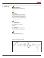
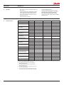
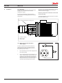
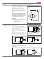
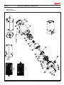
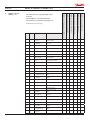
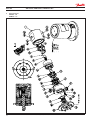
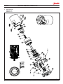
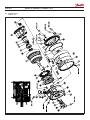
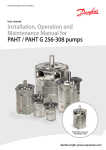
1
MAKING MODERN LIVING POSSIBLE
User manual
Installation, Operation and
Maintenance Manual
APP pumps (APP 0.6-1.0)
APP 0.6-1.0
ro-solutions.com
User manual
Installation, Operation and Maintenance APP Pumps (APP 0.6-1.0)
Table of Contents
Validity. . . . . . . . . . . . . . . . . . . . . . . . . . . . . . . . . . . . . . . . . . . . . . . . . . . . . . . . . . . . . . . . . . . . . . . . . . . . . . . . . . . . . . . . . . . . . 4
EU Declaration of Conformity . . . . . . . . . . . . . . . . . . . . . . . . . . . . . . . . . . . . . . . . . . . . . . . . . . . . . . . . . . . . . . . . . . . . . . . 5
2
1.
1.1
1.2
1.3
Introduction . . . . . . . . . . . . . . . . . . . . . . . . . . . . . . . . . . . . . . . . . . . . . . . . . . . . . . . . . . . . . . . . . . . . . . . . . . . . 6
General . . . . . . . . . . . . . . . . . . . . . . . . . . . . . . . . . . . . . . . . . . . . . . . . . . . . . . . . . . . . . . . . . . . . . . . . . . . . . . . . . 6
Symbols . . . . . . . . . . . . . . . . . . . . . . . . . . . . . . . . . . . . . . . . . . . . . . . . . . . . . . . . . . . . . . . . . . . . . . . . . . . . . . . . 6
Manufacturer and customer service address . . . . . . . . . . . . . . . . . . . . . . . . . . . . . . . . . . . . . . . . . . . . . 6
2.
2.1
2.2
2.3
2.4
2.5
Safety . . . . . . . . . . . . . . . . . . . . . . . . . . . . . . . . . . . . . . . . . . . . . . . . . . . . . . . . . . . . . . . . . . . . . . . . . . . . . . . . . . 7
General information. . . . . . . . . . . . . . . . . . . . . . . . . . . . . . . . . . . . . . . . . . . . . . . . . . . . . . . . . . . . . . . . . . . . . 7
Preferred system design. . . . . . . . . . . . . . . . . . . . . . . . . . . . . . . . . . . . . . . . . . . . . . . . . . . . . . . . . . . . . . . . . 7
Commissioning and servicing the unit . . . . . . . . . . . . . . . . . . . . . . . . . . . . . . . . . . . . . . . . . . . . . . . . . . . 7
Adhere to the following important points . . . . . . . . . . . . . . . . . . . . . . . . . . . . . . . . . . . . . . . . . . . . . . . 7
In case of doubt. . . . . . . . . . . . . . . . . . . . . . . . . . . . . . . . . . . . . . . . . . . . . . . . . . . . . . . . . . . . . . . . . . . . . . . . . 7
3.
3.1
3.2
3.3
3.4
3.5
3.6
3.7
3.8
3.9
3.10
Technical data . . . . . . . . . . . . . . . . . . . . . . . . . . . . . . . . . . . . . . . . . . . . . . . . . . . . . . . . . . . . . . . . . . . . . . . . . . 8
Approved applications and operational limits for the pumps . . . . . . . . . . . . . . . . . . . . . . . . . . . . . 8
Application range . . . . . . . . . . . . . . . . . . . . . . . . . . . . . . . . . . . . . . . . . . . . . . . . . . . . . . . . . . . . . . . . . . . . . . . 8
Electric motor data. . . . . . . . . . . . . . . . . . . . . . . . . . . . . . . . . . . . . . . . . . . . . . . . . . . . . . . . . . . . . . . . . . . . . . 8
Noise and vibration . . . . . . . . . . . . . . . . . . . . . . . . . . . . . . . . . . . . . . . . . . . . . . . . . . . . . . . . . . . . . . . . . . . . . 8
General arrangement . . . . . . . . . . . . . . . . . . . . . . . . . . . . . . . . . . . . . . . . . . . . . . . . . . . . . . . . . . . . . . . . . . . 8
Space requirement. . . . . . . . . . . . . . . . . . . . . . . . . . . . . . . . . . . . . . . . . . . . . . . . . . . . . . . . . . . . . . . . . . . . . . 8
Filtration. . . . . . . . . . . . . . . . . . . . . . . . . . . . . . . . . . . . . . . . . . . . . . . . . . . . . . . . . . . . . . . . . . . . . . . . . . . . . . . . 8
Properties of water. . . . . . . . . . . . . . . . . . . . . . . . . . . . . . . . . . . . . . . . . . . . . . . . . . . . . . . . . . . . . . . . . . . . . . 8
Air bubbles . . . . . . . . . . . . . . . . . . . . . . . . . . . . . . . . . . . . . . . . . . . . . . . . . . . . . . . . . . . . . . . . . . . . . . . . . . . . . 8
Chemicals. . . . . . . . . . . . . . . . . . . . . . . . . . . . . . . . . . . . . . . . . . . . . . . . . . . . . . . . . . . . . . . . . . . . . . . . . . . . . . . 8
4.
4.1
4.2
4.3
4.4
4.5
4.6
Arrival inspection, transportation, handling, lifting and storage . . . . . . . . . . . . . . . . . . . . . . . . . . 9
Arrival inspection . . . . . . . . . . . . . . . . . . . . . . . . . . . . . . . . . . . . . . . . . . . . . . . . . . . . . . . . . . . . . . . . . . . . . . . 9
Warning . . . . . . . . . . . . . . . . . . . . . . . . . . . . . . . . . . . . . . . . . . . . . . . . . . . . . . . . . . . . . . . . . . . . . . . . . . . . . . . . 9
General safety information . . . . . . . . . . . . . . . . . . . . . . . . . . . . . . . . . . . . . . . . . . . . . . . . . . . . . . . . . . . . . . 9
Transport and handling . . . . . . . . . . . . . . . . . . . . . . . . . . . . . . . . . . . . . . . . . . . . . . . . . . . . . . . . . . . . . . . . . 9
Return to supplier. . . . . . . . . . . . . . . . . . . . . . . . . . . . . . . . . . . . . . . . . . . . . . . . . . . . . . . . . . . . . . . . . . . . . .10
Storage . . . . . . . . . . . . . . . . . . . . . . . . . . . . . . . . . . . . . . . . . . . . . . . . . . . . . . . . . . . . . . . . . . . . . . . . . . . . . . . .10
5.
5.1
5.2
5.3
5.4
5.5
5.6
5.7
5.8
5.9
5.10
5.11
5.12
5.13
5.14
5.15
5.16
5.17
5.18
5.19
Installation and commissioning. . . . . . . . . . . . . . . . . . . . . . . . . . . . . . . . . . . . . . . . . . . . . . . . . . . . . . . . . 11
Important dimensions . . . . . . . . . . . . . . . . . . . . . . . . . . . . . . . . . . . . . . . . . . . . . . . . . . . . . . . . . . . . . . . . . 11
Cleanliness. . . . . . . . . . . . . . . . . . . . . . . . . . . . . . . . . . . . . . . . . . . . . . . . . . . . . . . . . . . . . . . . . . . . . . . . . . . . . 11
Fluid temperature. . . . . . . . . . . . . . . . . . . . . . . . . . . . . . . . . . . . . . . . . . . . . . . . . . . . . . . . . . . . . . . . . . . . . . 11
Electrical data. . . . . . . . . . . . . . . . . . . . . . . . . . . . . . . . . . . . . . . . . . . . . . . . . . . . . . . . . . . . . . . . . . . . . . . . . . 11
Local regulations. . . . . . . . . . . . . . . . . . . . . . . . . . . . . . . . . . . . . . . . . . . . . . . . . . . . . . . . . . . . . . . . . . . . . . . 11
Pre mounting checklist, based on Danfoss preferred system design . . . . . . . . . . . . . . . . . . . . . 11
Lifting and positioning . . . . . . . . . . . . . . . . . . . . . . . . . . . . . . . . . . . . . . . . . . . . . . . . . . . . . . . . . . . . . . . . .12
Mount the different equipment . . . . . . . . . . . . . . . . . . . . . . . . . . . . . . . . . . . . . . . . . . . . . . . . . . . . . . . .12
Electrics . . . . . . . . . . . . . . . . . . . . . . . . . . . . . . . . . . . . . . . . . . . . . . . . . . . . . . . . . . . . . . . . . . . . . . . . . . . . . . .12
Instrumentation . . . . . . . . . . . . . . . . . . . . . . . . . . . . . . . . . . . . . . . . . . . . . . . . . . . . . . . . . . . . . . . . . . . . . . .12
Connections . . . . . . . . . . . . . . . . . . . . . . . . . . . . . . . . . . . . . . . . . . . . . . . . . . . . . . . . . . . . . . . . . . . . . . . . . . .12
Ensure free flow . . . . . . . . . . . . . . . . . . . . . . . . . . . . . . . . . . . . . . . . . . . . . . . . . . . . . . . . . . . . . . . . . . . . . . .13
Verify setting of safety/relief valves . . . . . . . . . . . . . . . . . . . . . . . . . . . . . . . . . . . . . . . . . . . . . . . . . . . . .13
Flush the pump . . . . . . . . . . . . . . . . . . . . . . . . . . . . . . . . . . . . . . . . . . . . . . . . . . . . . . . . . . . . . . . . . . . . . . . .13
Bleed and remove air from the pump . . . . . . . . . . . . . . . . . . . . . . . . . . . . . . . . . . . . . . . . . . . . . . . . . . .13
Verify direction of rotation . . . . . . . . . . . . . . . . . . . . . . . . . . . . . . . . . . . . . . . . . . . . . . . . . . . . . . . . . . . . .13
Commissioning . . . . . . . . . . . . . . . . . . . . . . . . . . . . . . . . . . . . . . . . . . . . . . . . . . . . . . . . . . . . . . . . . . . . . . . .13
Check the filter condition. . . . . . . . . . . . . . . . . . . . . . . . . . . . . . . . . . . . . . . . . . . . . . . . . . . . . . . . . . . . . . .13
Instruct operator and maintenance personnel . . . . . . . . . . . . . . . . . . . . . . . . . . . . . . . . . . . . . . . . . .13
6.
6.1
6.2
Operation of motor pump unit . . . . . . . . . . . . . . . . . . . . . . . . . . . . . . . . . . . . . . . . . . . . . . . . . . . . . . . .14
General safety information . . . . . . . . . . . . . . . . . . . . . . . . . . . . . . . . . . . . . . . . . . . . . . . . . . . . . . . . . . . . .14
What to listen and look for . . . . . . . . . . . . . . . . . . . . . . . . . . . . . . . . . . . . . . . . . . . . . . . . . . . . . . . . . . . . .14
180R9262 / IOM APP Pumps - v01 / 09.2012
User manual
Installation, Operation and Maintenance APP Pumps (APP 0.6-1.0)
7.
7.1
7.2
7.3
7.4
7.5
7.6
7.7
7.8
Maintenance and service of the pump unit . . . . . . . . . . . . . . . . . . . . . . . . . . . . . . . . . . . . . . . . . . . . .15
General safety information . . . . . . . . . . . . . . . . . . . . . . . . . . . . . . . . . . . . . . . . . . . . . . . . . . . . . . . . . . . . .15
Service and inspection interval for the pump . . . . . . . . . . . . . . . . . . . . . . . . . . . . . . . . . . . . . . . . . . .15
Shut down of the system . . . . . . . . . . . . . . . . . . . . . . . . . . . . . . . . . . . . . . . . . . . . . . . . . . . . . . . . . . . . . . .15
Disassembling and assembling the pump unit . . . . . . . . . . . . . . . . . . . . . . . . . . . . . . . . . . . . . . . . . .15
Assembling the pump unit . . . . . . . . . . . . . . . . . . . . . . . . . . . . . . . . . . . . . . . . . . . . . . . . . . . . . . . . . . . . .16
Procedure for mounting pump back onto electric motor . . . . . . . . . . . . . . . . . . . . . . . . . . . . . . . .16
Getting the pump unit back into operation . . . . . . . . . . . . . . . . . . . . . . . . . . . . . . . . . . . . . . . . . . . . .16
Storage of the pump . . . . . . . . . . . . . . . . . . . . . . . . . . . . . . . . . . . . . . . . . . . . . . . . . . . . . . . . . . . . . . . . . . .16
8.
8.1
8.2
8.3
8.4
8.5
8.6
Troubleshooting and scrapping criteria . . . . . . . . . . . . . . . . . . . . . . . . . . . . . . . . . . . . . . . . . . . . . . . . .17
General safety information . . . . . . . . . . . . . . . . . . . . . . . . . . . . . . . . . . . . . . . . . . . . . . . . . . . . . . . . . . . . .17
Operational conditions which can cause pump failures. . . . . . . . . . . . . . . . . . . . . . . . . . . . . . . . . .17
Mechanical failure. . . . . . . . . . . . . . . . . . . . . . . . . . . . . . . . . . . . . . . . . . . . . . . . . . . . . . . . . . . . . . . . . . . . . .17
Electrical failure . . . . . . . . . . . . . . . . . . . . . . . . . . . . . . . . . . . . . . . . . . . . . . . . . . . . . . . . . . . . . . . . . . . . . . . .17
Responsibility. . . . . . . . . . . . . . . . . . . . . . . . . . . . . . . . . . . . . . . . . . . . . . . . . . . . . . . . . . . . . . . . . . . . . . . . . .17
Scrapping criteria . . . . . . . . . . . . . . . . . . . . . . . . . . . . . . . . . . . . . . . . . . . . . . . . . . . . . . . . . . . . . . . . . . . . . .17
Subject index . . . . . . . . . . . . . . . . . . . . . . . . . . . . . . . . . . . . . . . . . . . . . . . . . . . . . . . . . . . . . . . . . . . . . . . . . . . . . . . . . . . . .18
180R9262 / IOM APP Pumps - v01 / 09.2012
3
User manual
Installation, Operation and Maintenance APP Pumps (APP 0.6-1.0)
Validity
This manual is valid for APP pumps with the following code numbers/serial numbers:
APP 0.6
4
Code no.
180B3048
Serial no.
02
APP 0.8
Code no.
180B3037
Serial no.
02
APP 1.0
Code no.
180B3049
Serial no.
02
180R9262 / IOM APP Pumps - v01 / 09.2012
EU Declaration of Conformity
180R9262 / IOM APP Pumps - v01 / 09.2012
5
User manual
Installation, Operation and Maintenance APP Pumps (APP 0.6-1.0)
1.
1.1 General
The APP pumps and pump units are manufactured by Danfoss A/S, and are sold and marketed
by a net of authorized distributors world wide.
Introduction
This manual contains the necessary instructions
for the installation, operation and service of the
pumps used in a Sea Water Reverse Osmosis
(SWRO) or Brackish Water Reverse Osmosis
(BWRO) system.
The APP pumps must not be used for other
purposes than those recommended and
specified without first consulting your local
pump distributor.
Use of the pump in other applications not
suitable for the pump unit can cause damages to
the pump unit, with risk of personal injury.
1.2 Symbols
Indicates something to be noted by the
reader
Indicates a situation which will or could
result in damage to the pump and its
function
Indicates a situation which will or could
result in personal injury and/or damage
to the pump
Electrical hazard - Indicates a highvoltage warning
Safety glasses required
All personnel being responsible for operation
and maintenance of the pump unit must read
and fully understand these instructions,
especially the section “Safety” before:
Hearing protection required
•
•
•
Safety shoes required
•
•
•
•
Installing the pump unit
Connecting the motor pump unit to the
water system
Connecting the electric motor and instrumentation
Commissioning the unit
Servicing the motor pump unit, mechanic
and electric parts
Decommissioning the motor pump unit
The pump must always be installed and used in
accordance with existing national/local
sanitary, safety regulations and laws.
It is the responsibility of the safety officer or
the chief operator to assure compliance with all
local regulations that are not taken into
account in this manual.
Changing the pumps’ or motor pump units’
operational limits and hardware:
•
•
•
6
Ensure that these instructions are always
readily available to all personnel concerned.
Changes to the delivered pump or motor
pump system may only be done with a
written approval from Danfoss RO Solutions.
Operation outside the Danfoss specifications
requires a written approval from Danfoss RO
Solutions.
If any changes are made without written
approval the warranty will automatically
become void.
180R9262 / IOM APP Pumps - v01 / 09.2012
Safety helmet required
1.3 Manufacturer and customer service
address:
Danfoss A/S
RO Solutions
Nordborgvej 81, D25
DK-6430 Nordborg
Denmark
Telephone:
Fax:
Email:
Homepage:
+45 7488 4024
+45 7445 3831
[email protected]
www.ro-solutions.com
Your local Danfoss pump distributor can be
found on our homepage.
Data sheets and instructions on all accessories
are available on www.ro-solutions.danfoss.com
CE Declaration of Conformity can be found on
page 5.
User manual
2.
Installation, Operation and Maintenance APP Pumps (APP 0.6-1.0)
Safety
2.1 General information
Dangers that can arise from not following the
instructions:
When the pump or pump system is managed by
untrained personal, there is a danger of:
•
•
Death or fatal injuries
Costly damages and claims
Electrical
hazard
All electrical installation work must only be
carried out by authorized personnel in
accordance with EN60204-1 and/or local
regulations.
Install a lockable circuit breaker to avoid
inadvertent starting.
Protect the motor and other electrical equipment from overloads with suitable equipment.
!
Protective
garments
must be worn
It is recommended to place a local safety switch
near by the pump, enabling service personal to
cut power for the electric motor. This prevents
unintentionally starting the unit during servicing.
All pipe and hose connections must be stressfree mounted, securely fastened to the pumps
and well supported. Improper installation will or
could result in personal injury and/or damage to
the pump.
Use of this manual does not relieve operation
and maintenance personnel of the responsibility of applying normal good judgment in the
operation and care of the pump and its
components.
2.2 Preferred system design
Danfoss recommends building systems with a
high degree of safety. See Danfoss preferred
system design and PI&D in Data sheet and
Instruction which are found in appendix 1 (Data
sheet) and 2 (APP pump instruction).
It is always the system builders responsibility that
the system design does not cause any kind of
hazard and is adapted to local regulations and
standards.
Proper installation, care of start up and shutdown devices and over-pressure protection
equipment is essential.
Always wear suitable safety clothing when
handling the pump.
2.3 Commissioning and servicing the unit
It is recommended that commissioning and
servicing are carried out by a minimum of two
people, where one is acting as a supervisor.
When working near the pump system, safety
proof boot/shoes, safety glasses, ear protection
and safety helmet must always be worn.
2.4 Adhere to the following important
points
•
Under certain operational conditions the surface
of the pump can be above 60°C / 140°F.
Under these conditions the pump must be
labelled with a “Danger Hot” sign.
•
When using an electric motor, the motor must
always be supplied with adequate cooling
ventilation.
•
When using an electric motor together with a
VFD, the motor must be designed for operation
with VFD. VFD operation may increase the
temperature inside the electric motor if the
motor is not designed for VFD operation.
•
Before start-up, the settings for all protective
devices, for example, sensors/switches and
safety valves must be verified and free flow from
safety valves must be ensured.
180R9262 / IOM APP Pumps - v01 / 09.2012
•
Before using the pump/pump unit it is very
important to read and understand this user
manual.
Do not try to lift the pump unit manually;
most of the pumps weight more than
20 kilos, see specific weight for the pump
in the Data sheet, which is found in
appendix 1.
Do not run the pump if it is completely dry
and not bleeded.
Do not mount the pump without the bell
housing and a flexible coupling.
Do not try to start the unit before the
system components are mounted, bleeded
and adjusted.
2.5 In case of doubt
Please contact Danfoss A/S in case of doubt.
Contact information are listed in section 1.3,
Manufacturer and customer service address.
7
User manual
3.
Installation, Operation and Maintenance APP Pumps (APP 0.6-1.0)
Technical data
3.6 Space requirement
For service and replacement of the complete
motor pump unit, it is recommended having
sufficient space around the unit.
For easy access to the unit, at least 1 meter/
40 inches available space should be kept free
around the pump. When working with high
pressures, space demands should reflect the
required safety requirements.
3.1
Approved applications and operational
limits for the pumps
The pump and the pump units are designed for
the use in a Sea Water Reverse Osmosis (SWRO)
or Brackish Water Reverse Osmosis (BWRO)
systems.
The APP pumps must not be used for other
purposes than those recommended and
specified without first consulting your local
pump distributor.
Use of the pump in other applications not
suitable for the pump unit can cause damages
to the pump unit, with risk of personal injury.
For system integration of the pumps, please
see Data sheet and Instruction which are found
in appendix 1 (Data sheet) and 2 (APP pump
instruction).
3.2 Application range
See Data sheet in appendix 1.
3.3 Electric motor data
See recommended motor in Data sheet,
appendix 1 or IOM for motors, appendix 3. The
motors mentioned are the most common used
motors by Danfoss High Pressure Pumps.
3.4 Noise and vibration
Noise level for a motor pump unit with a
”standard” motor measured according to
EN ISO 3744:2010, see Data sheet in appendix 1.
Possibilities to reduce noise and vibration are
described in the same Data sheet.
3.5 General arrangement
Dimensions for the different pumps, see Data
sheet in appendix 1.
8
180R9262 / IOM APP Pumps - v01 / 09.2012
3.7 Filtration
(10µm absolute [ß10 =5000])
Requirements are specified in Data sheet,
appendix 1 and APP pump instruction, appendix
2.
Danfoss recommends not to build a filter bypass
function or use filters with an integrated bypass.
If the above recommendation is not followed the
warranty for the pump will automatically
become void.
It should be possible to monitor the condition of
the filter via the differential/delta pressure across
the filter.
Using insufficient filtration or a filter bypass
can cause a failure or decreased service life of
the pumps.
3.8 Properties of water
It is recommended NOT to use the pumps in feed
water concentrations higher than 50,000 ppm
TDS without consulting your local Danfoss pump
distributor.
3.9 Air bubbles
Large bubbles in a pressurised RO system can
result in damage to piping, equipment and the
pumps.
All air must be bleeded from both the lowpressure and high-pressure side before the RO
system is pressurised. Special consideration
should also be given to air bubbles in feed flow
and continuously feed into the pumps as it else
can give cavitation.
3.10 Chemicals
The pumps should not be exposed to any
chemicals that can result in damage to piping,
equipment and internal parts of the pumps.
User manual
Installation, Operation and Maintenance APP Pumps (APP 0.6-1.0)
4.
4.1 Arrival inspection
The pump is packed in a cardboard or wood box
with plugs in the port connections to protect the
pumps from damage during transportation.
Arrival inspection,
transportation,
handling, lifting and
storage
Pumps which have a weight above 20 kilos (see
Data sheet, appendix 1) must be handled by
using lifting eyes and slings.
Immediately check the shipment for damage on
arrival and make sure that the name plate/type
designation is in accordance with the packing
slip and your order.
Remove all packing materials immediately after
delivery. In case of damage and/or missing parts,
a report should be drawn up and presented to
the carrier at once.
4.2 Warning
Before any lifting operation is performed,
environmental conditions must be taken into
consideration (Ex-rated areas, wind speed, wet/
dry conditions, lifting height, etc.).
4.3 General safety information
Personnel involved in lifting and transporting the
equipment (see Safety, chapter 2) must be
trained in handling and safety procedures when
lifting heavy loads. Many of the pumps and
pump units weigh more than 20 kilos, which
requires lifting slings and suitable lifting devices;
e.g. an overhead crane or industrial truck to be
used as minimum.
4.4 Transport and handling
Small pumps which have a weight below 20 kilos
(weight can be found in the Data sheet in
appendix 1) can be handled by hand if they are
not mounted together with an electric motor.
The weight of a small pump with a motor will be
above 20 kilos.
Never use only one sling and make sure the
slings does not slip off the pump.
When the pump is mounted together with an
electric motor, the pump unit always weight
more than 20 kilos and must be handled by using
slings around the pump unit.
180R9262 / IOM APP Pumps - v01 / 09.2012
9
User manual
Installation, Operation and Maintenance APP Pumps (APP 0.6-1.0)
See below examples of where to/not to attach
the lifting slings on the pump unit:
Correct lifting with 2 separate slings:
Incorrect lifting can result in personally injury
and/or damage to the pump unit.
4.5 Return to supplier
Please see maintenance chapter 7.
4.6 Storage
Each pump is tested before shipment and
therefore holds water, so for storage temperature and frost protection see Data sheet in
appendix 1 or APP pump instruction in appendix
2.
The pumps are NOT delivered frost protected
from the factory.
Wrong lifting:
When lifting the pump unit, one sling must be
attached to the electric motor and one sling
around the pump.
Only some motors and pumps have specific
lifting eyes.
Do not use connections/nozzles for lifting!
Do not use only one sling!
Make sure that the unit/load is balanced before
attempting to lift, as the centre of the mass is
different from pump to pump and pump unit to
pump unit.
How to mount the pump and the electric motor
correctly together, see Data sheet in appendix 1
or APP pump instruction in appendix 2.
10
180R9262 / IOM APP Pumps - v01 / 09.2012
User manual
5.
Installation and
commissioning
Installation, Operation and Maintenance APP Pumps (APP 0.6-1.0)
5.1 Important dimensions
Physical dimensions and connections for the
pump unit are described in Data sheet,
appendix 1.
5.2 Cleanliness
It is very important that the tubes and pipes are
completely clean: no dirt, chips or burrs are
allowed. Flush all piping before connecting the
high pressure pump to ensure the system is
clean. Internal surfaces of the piping must not be
corroded. If dirt or rust is not removed, the pump
and the valves can be damaged and in the worst
case damaged beyond repair!
5.3 Fluid temperature
Before start-up, the fluid and pump housing
temperature must be above the minimum
start-up temperature, see Data sheet,
appendix 1.
5.4 Electrical data
Check voltage, current frequency and rated
power on the electric motor and VFD setting
name plate on both the motor and the VFD.
5.5 Local regulations
Commissioning must always be done in
accordance with valid regulations and local
standards.
5.6 Pre mounting checklist, based on
Danfoss preferred system design
Schematic 1: Recommended system design
180R9262 / IOM APP Pumps - v01 / 09.2012
11
User manual
Installation, Operation and Maintenance APP Pumps (APP 0.6-1.0)
Table 1: Check points when assembling and commissioning system
Check points
Comment
CP1
Ensure that the environmental conditions are safe.
See Arrival inspection,
transportation, handling,
lifting and storage, chapter 4.
CP2
Minimum and maximum start-up temperature for fluid and
pump.
See Data sheet or Instruction,
appendices 1 and 2.
CP3
Filtration condition (10µm absolute (ß10 = 5000)
See Danfoss requirements in
Data sheet and Instruction,
appendices 1 and 2
CP4
Power supply for electric motor and VFD.
See Data sheet for the used
motor and VFD, appendix 1.
CP5
Safety circuit / breaker must be sized for the motor and
environment (corrosion and humidity)
See Data sheet for the used
safety circuit, appendix 1.
CP6
Bolts and screws must conform to environmental conditions
as well as fluid and torque requirements.
CP7
Instrumentation, pressure switch should be designed to
conform to the environment (corrosion and humidity).
See Data sheet for the used
equipment, appendix 1.
CP8
Check the factory settings of the safety/relief valves or
pressure relief valves (8 & 9).
See Data sheets for the used
valves, appendix 1.
CP9
Check the settings of the pressure transmitter/switch (3) set
at min. inlet pressure.
See Data sheet or Instruction,
appendices 1 and 2.
CP10
Check that all pressure indicators (PI) are selected to be able
to measure the system pressure range.
Scaling should at least be 1 Bar
or more precise.
CP11
Check coupling distance ( air gab – movement of the spider )
3 – 5 mm
CP12
Check correct connections on the pump ( in & outlet)
CP13
Check piping for possible air gaps.
5.7 Lifting and positioning
Lift the pump unit onto base (Remember
vibration dampers, if needed). Fasten the motor
to the base.
See also chapter 4, Arrival inspection, transportation, handling, lifting and storage.
5.8 Mount the different equipment
(connections, pipes, tubes, check and safety/relief
valves, etc.)
•
•
•
•
•
12
The hard piping and flexible hoses used must
be of proper design and must be installed in
accordance with the manufacturer’s recommendations. (see also Data sheet for Hose
and hose fittings and Instruction for
Assembling Hose kit - both available on
www.ro-solutions.danfoss.com).
Misalignment of the hard pipes may place
stress on the pump port connection and may
damage the pump.
Prevent excessive external pipe load.
Do not connect piping by applying external
force (use of wrenches, crane, etc.) Piping
must be aligned without residual stress.
Do not mount expansion joints so that their
force applies internal pressure on the pump
connections.
180R9262 / IOM APP Pumps - v01 / 09.2012
OK ?
5.9 Electrics
All electrical installation work must be carried
out by authorized personnel in accordance with
EN60204-1 and/or local regulations. (see also
Safety, chapter 2)
Mount the safety circuit breaker, turn the circuit
off and lock it in the off position.
Mount the power cable on the electric motor.
If a VFD is used, adjust the protective motor
switch/VFD to the current limits found on name
plate of the electric motor.
5.10 Instrumentation
The pressure switch/sensor should be mounted
as close to the pump as possible. It is recommended to test the pressure/sensor switch via an
instrumentation manifold.
Mount the pressure switch/sensors according to
the manufacturer’s instructions.
5.11 Connections
Mount connections and maybe check valve(s).
Mount and tighten as specified.
User manual
Installation, Operation and Maintenance APP Pumps (APP 0.6-1.0)
5.12 Ensure free flow
Ensure that the flow from safety/relief valves 8
and 9 is completely unhindered. A blocked
safety/relief valve can cause excessive build-up
of pressure and thereby cause dangerous
situations and damage to the whole system.
5.13 Verify setting of safety/relief valves
Make sure, the safety/relief valves 8 and 9 are
placed correctly.
Check the pressure settings on the name plates
of the safety/relief valves. If they are OK,
continue. Otherwise replace the safety/relief
valves.
5.14 Flush the pump
Fully open the pressure valve at the brine site.
Close all the bleeding and draining plugs on the
high pressure pump.
Start the feed pump and ensure that the flow
from the feed pump to the high pressure pump
is unhindered.
•
•
Adjust the pressures to the specified inlet
and outlet pressure for the system and let
the pump unit run until the electric motor
and pump temperature is stable.
If the system is running within the system
design limits, the system is released for
operation.
5.18 Check the filter condition
Evaluate dirt found in filter, replace filter
elements, if necessary.
5.19 Instruct operator and maintenance
personnel
Before using the pump/pump unit, the personnel
must be instructed in using the pump/pump
unit, its function, components, documentation
and safety.
Danfoss offers commissioning and service at
system manufacturer’s location. Rate quotes are
offered upon request.
5.15 Bleed and remove air from the pump
Open bleeding plugs. Keep the plugs open until
only water leaves the high pressure pump.
5.16 Verify direction of rotation
An arrow can be found on the pump or pump
unit. The direction of rotation must always follow
the arrow.
Unlock the safety circuit breaker. Start the motor
for 1 second and observe the direction of
rotation either looking on the fan of the motor or
on the coupling true the hole in the bell housing
(not available on all bell houses). If the motor is
turning the wrong direction, switch two phases
in the connection box of the motor or reprogram
the direction in VFD.
5.17
•
•
•
•
•
•
•
•
Commissioning
Close all the bleeding and draining plugs.
Open the pressure valve at the brine site.
Switch the safety circuit breaker on for both
motor(s) and VFD(s).
Start the feed pump.
Start the high pressure pump.
If a VFD or a soft starter is used a ramp up
time of minimum 10 second is required to
avoid damage of internal pump parts.
Monitor the inlet pressure and outlet
pressure of the high pressure pump and
look for leakages.
Check the pressure indicator function by
slowly closing the valves. The pump unit
should stop when the minimum inlet
pressure and maximum outlet pressure has
been reached.
180R9262 / IOM APP Pumps - v01 / 09.2012
13
User manual
6.
Operation of motor
pump unit
Installation, Operation and Maintenance APP Pumps (APP 0.6-1.0)
6.1 General safety information
Before inspecting the pump unit, read the Safety
chapter 2 in this user manual.
6.2 What to listen and look for
If the following is observed, please act as
indicated:
A)
Re-check all bolts and, if necessary, contact
the maintenance department in order to
have all bolts tighten to the specified levels.
B)
Leakage – if a small leak dripping from the
bell housing is observed, contact the
maintenance department.
C)
Leakage – if there is a large leak, the unit
should be stopped as soon as possible.
Contact the maintenance department.
D)
High frequency tones – safety/relief valves
are either damaged or running very close
to their cracking pressure, stop the unit
immediately. Contact the maintenance
department.
E)
Non-standard noise or vibration from the
pump requires the unit to be stopped
immediately. Contact the maintenance
department.
F)
Very high temperatures – can indicate one
or more damaged parts inside the pump.
The pump then needs to be stopped
immediately and inspected before running
again. Contact the maintenance department.
G)
Drop in flow and/or pressure - can indicate
wear on one or more parts inside the
pump. The pump needs to be stopped
immediately and inspected before running
again. Contact the maintenance department.
H)
Other observations or troubles, please see
appendix 7, Right and Wrong or the Trouble
shooting guide, appendix 6.
Both appendices give good advises on
design, installation, wiring and troubleshooting.
If the pump is not stopped for inspection, it can
lead to damage of the pump. See also service
and warranty section in the Data sheet, appendix
1; APP pump instruction or Instruction for
recommended service intervals in appendix 2
and 4.
Danfoss offers service of the pump at the system
manufacturer’s location as well as training in
servicing the pump. Quotes are offered upon
request.
14
180R9262 / IOM APP Pumps - v01 / 09.2012
Danfoss recommends at the same time also to
check the filter and membrane condition and
evaluate dirt found, replace filter and membrane
elements if necessary.
User manual
7.
Maintenance and
service of the pump
unit
Installation, Operation and Maintenance APP Pumps (APP 0.6-1.0)
7.1 General safety information
Before servicing the pump unit, it is necessary to
read and understand this user manual, especially
the Safety, chapter 2. Remember to wear suitable
safety equipment according to Safety, chapter 2.
7.2
Service and inspection interval for the
pump
Maintenance and service intervals are depending
on the cleanness level of the water, hydraulic
load and temperature of the pump unit. The
most important parameter is the cleanness of the
water.
See the section Service and warranty in the Data
sheet, appendix 1, APP pump instruction and
Instruction for recommended service intervals in
appendix 2 and 4.
For spare parts and service tools, please see Parts
list, appendix 5.
Danfoss offers service of the pump at the system
manufacturer’s location and training in servicing
the pump. Quotes are offered upon request.
motor and afterwards unscrew the bolts/
nuts holding the pump and bell housing
together.
I)
Carefully pull the pump out of the bell
housing by using lifting equipment, if
necessary.
J)
Hold the pump in different positions above
a drip tray; this should allow most of the
left-over water trapped in the pump to drip
out. Clean and dry the pump surface and
plug the bleeding and draining plugs.
K)
Move the pump to a clean and safe location
where the pump can be inspected/
serviced.
7.4
Disassembling and assembling the
pump unit
Remove all connections from the pump.
A)
B)
Disassemble the pump according to the
Disassembling and Assembling Instruction
(available at www.ro-solutions.danfoss.com
At the website you can also find the
Changing pistons instructions for APP 11-13
and APP 16-22 as well as for APP 21-38).
Clean all the parts and surfaces with a fluid
compatible with the materials found in the
pump. Wipe the parts clean and dry with a
dry and lint-free cloth.
7.3
A)
Shut down of the system
Open the pressure valves at the brine site
to release the pressure.
B)
Stop the high pressure pump.
C)
Stop the feed pump.
C)
D)
Turn on the motor safety circuit breaker for
both the high pressure pump, the feed
pump and the VDF if used and lock them.
Only the employees servicing the pump
unit should be able to unlock/activate the
switch again.
Inspect all parts including shaft seal and if
necessary, replace them; see Parts list,
appendix 5 and APP pump instruction,
appendix 2 or general instruction for
Recommended service intervals, appendix
4.
D)
If the pump is going to be returned to
Danfoss for repair or a warranty claim, it is
important that Danfoss, besides your
contact information and reason for
returning, gets the below information
before shipping.
E)
Open bleeding and drain plugs. Wait until
the pump and system are emptied for
water.
F)
Slowly unscrew and remove the bolts and
gaskets from the in/out hoses or pipes, be
careful about jets of water. Be aware that
there still can be pressure in the system,
which will be released when unscrewing
and removing the bolts and gaskets.
G)
Attach the lifting equipment to the pump
unit. For instructions on lifting the
complete pump unit, see chapter 4, Arrival
inspection, transportation, handling, lifting
and storage.
H)
For the small pumps unscrew the bolts
holding the pump to the bell housing and
for the bigger pumps, unscrew the bolts
holding the pump and bell housing to the
180R9262 / IOM APP Pumps - v01 / 09.2012
After Danfoss has been informed about the
return, you will receive a return number
and a template to fill out. One copy should
be attached to the shipment and one copy
should be sent to the E-mail address on the
template.
Returns without a return number will be
rejected !!!
15
User manual
Installation, Operation and Maintenance APP Pumps (APP 0.6-1.0)
7.5 Assembling the pump unit
Assemble the pump according to the Disassembling and Assembling Instruction
(available at www.ro-solutions.danfoss.com).
7.6
Procedure for mounting pump back
onto electric motor
Do always follow the procedure delivered with
the instructions from the coupling manufacturer!
Mount the flexible coupling and bell housing
according to the Data sheet, appendix 1 and APP
pump instruction, appendix 2.
7.7
Getting the pump unit back into
operation
Find instructions of how to put the pump unit
back into operation in chapter 4, Arrival inspection, transportation, handling, lifting and storage
and Installation and commissioning, chapter 5.
7.8 Storage of the pump
If the pump has to be shut down for a longer
period or put on the shelf, instructions can be
found in Storage-chapter in Data Sheet, appendix 1 or APP pump instruction, appendix 2.
16
180R9262 / IOM APP Pumps - v01 / 09.2012
User manual
8.
Troubleshooting and
scrapping criteria
Installation, Operation and Maintenance APP Pumps (APP 0.6-1.0)
8.1 General safety information
Before inspecting the pump unit, it is necessary
to read and understand this user manual,
especially the Safety chapter 2.
Remember to wear suitable safety equipment
according to Safety chapter 2.
8.2 Operational conditions which can cause
pump failures
The following conditions can cause a pump
failure :
•
•
•
•
•
•
•
•
•
•
•
•
•
Thepumpisrunningdry.
Theinletpressureistoohigh.
Theinletpressureistoolow.
Theviscosityofthefluidistoohigh.
Thetemperatureofthefluidbeing
pumped is too high.
Theambienttemperatureistoohigh.
Thepumpisrunningagainstablocked
port/closed manual valve.
Thepumpisoperatingatapressureabove
the operational specification.
Thepumpisrunningwithanon-specified/
approved fluid.
Thepumpisrunninginthewrong
direction.
Thefiltrationisinsufficient.
Thepumpisnotbeingservicedaccording
to Danfoss specifications (end of life).
Thereisexcessivemechanicalloadonthe
shaft coupling and piping.
If a VFD is used and wrongly programmed, it can
damage the pump and lead to high temperatures or other dangers.
Therefore all electrical installation work must
only be carried out by authorized personnel in
accordance with EN60204-1 and/or local
regulations.
8.5 Responsibility
Danfoss takes no responsibility for any other
abnormal injuries, risks or damages that could
arise caused by abnormal conditions, vibrations,
corrosion, abrasives, foreign objects or excessive
temperatures and shall not be liable for any
consequential or incidental damages.
8.6 Scrapping criteria
Whether the pump can be repaired or need to be
scrapped depends on how damaged the internal
parts are or how damaged the whole unit is.
Please use appendix 6, Trouble shooting guide as
guideline or send the pump to Danfoss headquarter in Denmark for evaluation.
For other observations or troubles, please see
appendix 7, Right and Wrong which gives good
advises in design, installation, wiring and
troubleshooting.
8.3 Mechanical failure
If the pump is running dry, the temperature will
quickly increase which can be dangerous,
depending on how long time the pump is
running dry.
If there is any leaking at start up or leaking arises
during operation, the high pressure can lead to
eye or skin damage.
Leaking can result in flooding, which again can
cause a risk of slipping, tripping or falling.
If water is dripping into the electric motor; it can
lead to electric shock, fire, short of circuit or even
death. In order to avoid water dripping into the
electric motor, see Installation and commissioning, chapter 5 and Operation, chapter 6.
Electrical
hazard
8.4 Electrical failure
If the wiring/connection of the electric motor is
not correct or the earth connection is missing, it
can lead to electric shock, burn damages, fire or
even death.
180R9262 / IOM APP Pumps - v01 / 09.2012
17
User manual
Installation, Operation and Maintenance APP Pumps (APP 0.6-1.0)
Subject index
A
Address . . . . . . . . . . . . . . . . . . . 6, 7, 15
Air bubbles . . . . . . . . . . . . . . . . . . . . . 8
Appendix . . . .7, 8, 9, 10, 11, 12, 14, 15, 16, 17
Application range . . . . . . . . . . . . . . . . . 8
Approval . . . . . . . . . . . . . . . . . . . . . . . 6
Arrival . . . . . . . . . . . . . . . . . 9, 12, 15, 16
Assembling . . . . . . . . . . . . . . . .12, 15, 16
B
Bleed . . . . . . . . . . . . . . . . . . . 7, 8, 13, 15
C
Checklist . . . . .
Check points . .
Chemicals . . . .
Cleanliness . . .
Commissioning
Connections . .
Coupling . . . . .
.
.
.
.
.
.
.
.
.
.
.
.
.
.
.
.
.
.
.
.
.
.
.
.
.
.
.
.
.
.
.
.
.
.
.
. . . . . . . . . . . . 11
. . . . . . . . . . . . 12
. . . . . . . . . . . . .8
. . . . . . . . . . . . 11
.6, 7, 11, 12, 13, 16, 17
. . . 7, 9, 10, 11, 12, 15
. . . . 7, 12, 13, 16, 17
D
Danger . . . . . . . . . . . . . . . . . . . .7, 13, 17
Data sheet . . . . . . 7, 8, 9, 10, 11, 12, 14, 15, 16
Declaration of Conformity . . . . . . . . . 5, 6
Design . . . . . . . . . . . . 7, 8, 9, 11, 12, 14, 17
Distributor. . . . . . . . . . . . . . . . . . . . 6, 8
Dimensions . . . . . . . . . . . . . . . . . . .8, 11
Disassembling . . . . . . . . . . . . . . . . 15, 16
E
Electric motor . 6, 7, 8, 9, 10, 11, 12, 13, 16, 17
Electrical failure . . . . . . . . . . . . . . . . . 17
Electrical hazard . . . . . . . . . . . . . . . . . . 6
Electrics . . . . . . . . . . . . . . . . . . . . . . 12
EU Declaration of Conformity . . . . . . . . . 5
F
Failure . . . . . .
Filter condition.
Filtration . . . . .
Flow . . . . . . .
Fluid. . . . . . . .
Flush . . . . . . .
.
.
.
.
.
.
.
.
.
.
.
.
.
.
.
.
.
.
.
.
.
.
.
.
.
.
.
.
.
.
.
.
.
.
.
.
.
.
.
.
.
.
.
.
.
.
.
.
.
.
.
.
.
.
.
.
.
.
.
.
. . . . . .8, 17
. . . . . . . 13
. . . 8, 12, 17
. . 7, 8, 13, 14
.11, 12, 15, 17
. . . . . 11, 13
G
General information . . . . . . . . . . . . . . . 7
Guideline . . . . . . . . . . . . . . . . . . . . . 17
H
Handling . . . . . . . . . . . . . . . 7, 9, 12, 15, 16
I
Inspection . . . . .
Installation . . . .
Instruction. . . . .
Instrumentation .
Introduction . . .
.
.
.
.
.
.
.
.
.
.
. . . . . . 9, 12, 14, 15, 16
. . .6, 7, 11, 12, 14, 16, 17
. 6, 7, 8, 10, 12, 14, 15, 16
. . . . . . . . . . . . .6, 12
. . . . . . . . . . . . . . .6
M
Maintenance . . . . . . . . . .6, 7, 10, 13, 14, 15
Mechanical failure. . . . . . . . . . . . . . . . 17
Mounting . . . . . . . . . . . . . . . . . . . . . 16
N
Name plate . . . . . . . . . . . . . . 9, 11, 12, 13
Noise . . . . . . . . . . . . . . . . . . . . . . . . 14
L
Leaking. . . . . . . . . . . . . . . . . . . . . . . 17
Lifting . . . . . . . . . . . . . 6, 9, 10, 12, 15, 16
Local regulations . . . . . . . . . 6, 7, 11, 12, 17
S
Safety. . . . . . . . .
Safety valve . . . . .
Scrapping criteria .
Serial number . . .
Servicing. . . . . . .
Shut down. . . . . .
Space requirement
Spare part . . . . . .
Start up. . . . . . . .
Storage. . . . . . . .
Symbols . . . . . . .
System . . . . . . . .
Systems . . . . . . .
.6, 7, 8, 9, 12, 13, 14, 15, 17
. . . . . . . . . . . . . . . .7
. . . . . . . . . . . . . . . 17
. . . . . . . . . . . . . . . .4
. . . . . . . . . . 6, 7, 14, 15
. . . . . . . . . . . . . 15, 16
. . . . . . . . . . . . . . . .8
. . . . . . . . . . . . . . . 15
. . . . . . . . . . . . . . 7, 17
. . . . . . . 9, 10, 12, 15, 16
. . . . . . . . . . . . . . . .6
. . 6, 7, 8, 11, 12, 13, 14, 15
. . . . . . . . . . . . . . 7, 8
T
Table of content .
Technical data . .
Temperature . . .
Transportation . .
Trouble shooting
. . . . . . . . . . . . . . . .2
. . . . . . . . . . . . . . . .8
.7, 10, 11, 12, 13, 14, 15, 17
. . . . . . . . 6, 9, 12, 15, 16
. . . . . . . . . . . . . 14, 17
.
.
.
.
.
V
Valve . . . . . . . . . . . . 7, 11, 12, 13, 14, 15, 17
W
Warning . . . . . . . . . . . . . . . . . . . . . 6, 9
O
Operation . . . . . . . . .6, 7, 8, 9, 13, 14, 16, 17
Operational conditions . . . . . . . . . . . 7, 17
P
Piping. . . . . . . . . . . . .
Positioning . . . . . . . . .
Preferred system design .
Pre mounting. . . . . . . .
Protection . . . . . . . . . .
.
.
.
.
.
.
.
.
.
.
.
.
.
.
.
.
.
.
.
.
.
.
.
.
.
8, 11, 12, 17
. . . . . . 12
. . . . . 7, 11
. . . . . . 11
. . . 6, 7, 10
R
Relief valve . .
Responsibility
Return . . . . .
Rotation . . . .
.
.
.
.
.
.
.
.
.
.
.
.
.
.
.
.
.
.
.
.
.
.
.
.
.
.
.
.
.
.
.
.
.
.
.
.
.
.
.
.
.
.
.
.
.
.
.
.
.
.
.
.
.12, 13, 14
. . 6, 7, 17
. . . 10, 15
. . . . . 13
Danfoss A/S
High Pressure Pumps
DK-6430 Nordborg
Denmark
Danfoss can accept no responsibility for possible errors in catalogues, brochures and other printed material. Danfoss reserves the right to alter its products without notice.
This also applies to products already on order provided that such alterations can be made without subsequential changes being necessary in specifications already agreed.
All trademarks in this material are property of the respective companies. Danfoss and the Danfoss logotype are trademarks of Danfoss A/S. All rights reserved.
18
180R9262 / IOM APP Pumps - v01 / 09.2012
MAKING MODERN LIVING POSSIBLE
Front page for Appendices
User manual
Appendices for Installation,
Operation and Maintenance Manual
APP pumps (APP 0.6-1.0)
APP 0.6-1.0
ro-solutions.com
User manual
Appendices for IOM APP Pumps (APP 0.6-1.0)
Table of Contents
1.
Data sheet for APP 0.6-1.0 pumps (521B1136) . . . . . . . . . . . . . . . . . . . . . . . . . . . . . . . . . . . . . . . . . . . . . 3
2.
APP pump instruction APP 0.6-3.5 (180R9065) . . . . . . . . . . . . . . . . . . . . . . . . . . . . . . . . . . . . . . . . . .13
3.
IOM Electric motors (180R9230). . . . . . . . . . . . . . . . . . . . . . . . . . . . . . . . . . . . . . . . . . . . . . . . . . . . . . . . . . 21
4.
Recommended service intervals for APP pumps (180R9199) . . . . . . . . . . . . . . . . . . . . . . . . . . . . .25
5.
APP Parts list (521B0941). . . . . . . . . . . . . . . . . . . . . . . . . . . . . . . . . . . . . . . . . . . . . . . . . . . . . . . . . . . . . . . .29
6.
Trouble shooting guide . . . . . . . . . . . . . . . . . . . . . . . . . . . . . . . . . . . . . . . . . . . . . . . . . . . . . . . . . . . . . . . .53
7.
Right and wrong (180R9042) . . . . . . . . . . . . . . . . . . . . . . . . . . . . . . . . . . . . . . . . . . . . . . . . . . . . . . . . . . .63
2
180R9262 / IOM APP 0.6-1.0 Appendices - v01 / 09.2012
MAKING MODERN LIVING POSSIBLE
1.
Data sheet for APP
0.6-1.0 pumps (521B1136)
Data sheet
Data sheet
APP 0.6-1.0
ro-solutions.com
Data sheet
APP 0.6-1.0
Data sheet for
APP 0.6-1.0 pumps
(521B1136)
1.
General information
2.
Benefits
Table of Contents
3.
Technical data
4.
Flow at different rpm
5.
Flushing valve
6.
Power requirements
7.
7.1
7.2
Temperature and corrosion
Operation
Storage
8.
Noise level
9.
Filtration
10.
10.1
10.2
Dimensions
Pump
Complete unit
11.
11.1
11.2
11.3
Installation
Mounting
Open-ended system with direct water supply
RO system with APP pump
12.
12.1
12.2
12.3
Service
Warranty
Maintenance
Repair
1.
General information
a constantly high efficiency and minimum of
service required.
APP 0.6, APP 0.8 and APP1.0 pumps are designed
to supply low viscosity and corrosive fluids under
high pressure, eg in seawater reverse osmosis
filtration applications and for high-pressure salt
water pumping.
The pumps are fixed displacement pumps in
which the flow is proportional to the number of
revolutions of the input shaft and the pump
displacement, regardless of any counter-pressure.
The pumps are based on the axial piston
principle enabling a very light and compact
design. The design ensures that lubrication of
the moving parts in the pumps is provided by
the fluid itself. No oil lubrication is thus required.
The pumps are supplied with an integrated
flushing valve that allows the salt water to flow
from inlet to the outlet, when the pump is not
running.
All parts included in the pumps are designed to
provide long service life, ie long service life with
1
1:
2:
3:
4:
5:
6:
7:
8:
9:
10:
11:
12:
2
11
7
4
6
Shaft sealing
Mounting flange
Retaining ring
Piston/shoe
Valve plate
Swash plate
Cylinder barrel
Spring
Port plate
Connecting flange
Housing with bearing
Flushing valve
10
4
2
12
180R9262
IOM APP 0.6-1.0 Appendices
- v01 / 09.2012
521B1136 // DKCFN.PD.013.J3.02
/ 09.2012
9
5
11
8
3
Data sheet
APP 0.6-1.0
2.
•
Benefits
•
•
•
•
3.
Technical data
One of the smallest and lightest pumps on
the market.
Can be powered by a combustion engine.
Long service life / No preventive maintenance required in the warranty period.
Generates insignificant pulsations in the
high-pressure line.
No oil lubricant required.
•
•
•
•
Integrated flushing valve
All parts of the pump are made of high
corrosion resistant materials e.g. Duplex
(EN1.4462/UNS S31803-S32205) and
Super Duplex (EN1.4410/UNS S32750)
stainless steel and carbon reinforced PEEK
High efficiency
APP pumps
APP 0.6
APP 0.8
Code number
180B3048
180B3037
APP 1.0
180B3049
Geometric displacement
cm3/rpm
4
5.07
6.3
in3/rpm
0.24
0.31
0.38
Rated flow
(3000 rpm) 1)
m3/h
0.6
0.8
1.0
gpm
2.6
3.5
4.4
Outlet min. pressure 2)
bar
20
20
20
psi
290
290
290
Outlet max. pressure,
continuous. 3)
bar
80
80
80
psi
1160
1160
1160
Outlet max. pressure,
intermittent 4)
bar
100
100
100
psi
1450
1450
1450
Inlet min. pressure
bar
0.5
0.5
0.5
psi
7.3
7.3
7.3
bar
5
5
5
psi
72.5
72.5
72.5
Inlet max. pressure,
continuous
Inlet max. pressure, peak
bar
10
10
10
psi
145
145
145
Max. speed continuous 5)
rpm
3450
3450
3450
Min. speed continuous
rpm
700
700
700
Power requirement at
80 bar and 3000 rpm
kW
1.9
2.4
2.9
hp
2.5
3.3
3.9
Torque at 80 bar
Nm
6.1
7.6
9.3
lbf-ft
4.5
5.6
6.85
Kg
5.2
5.2
5.2
lb
9.7
9.7
9.7
YES
YES
YES
Weight
Integrated flushing valve
1) Typical average flow at 80 bar (1160 psi).
2) For lower pressure, please contact Danfoss
RO Sales Organization.
3) For higher pressure, please contact Danfoss
RO Sales Organzation.
4) Intermittent pressure is acceptable for less than
10 seconds per minute.
5) For speeds above 3000 rpm the pump must be
boosted at a pressure of 1-5 bar (14.5 - 72.5 psi).
180R9262 // DKCFN.PD.013.J3.02
IOM APP 0.6-1.0 Appendices
521B1136
/ 09.2012- v01 / 09.2012
5
3
Data sheet
APP 0.6-1.0
4.
Using the diagram shown below, it is easy to
select the pump which fits the application best if
the flow required and the rotation speed (rpm) of
the pump are known.
Flow at different rpm
m3/h
1,4
1,2
APP
1.01.0
APP
1
APP
0.80.8
APP
0,8
APP
APP
0.60.6
0,6
0,4
0,2
0
0
500
1000
1500
2000
2500
3000
3500
rpm
Furthermore, this diagram shows that the flow
can be changed by changing the rotation speed
of the pump. The flow/rpm ratio is constant, and
the “required “ flow can be obtained by changing
the rotation speed to a corresponding value.
Thus, the required rpm can be determined as:
5.
Flushing valve
Required rpm =
Required flow × Rated rpm
Rated flow
The diagram shows pressure difference across
flushing valve:
APP 0.6-1.0 flushing
Flushingvalve
valvecharacteristic
characteristic
APP0.6-1.0
18
16
Flow[l/min]
14
12
10
flow[l/min]
8
6
4
2
0
0
1
2
3
Pressure [bar]
6
4
180R9262
IOM APP 0.6-1.0 Appendices
- v01 / 09.2012
521B1136 // DKCFN.PD.013.J3.02
/ 09.2012
4
5
Data sheet
6.
Power requirements
APP 0.6-1.0
Pump
model
Flow
Pressure
60 bar
70 bar
rpm
Calc.
factor
475.8
80 bar
l/min
m3/h
gpm
870 psi
1015 psi
1160 psi
APP 0.6
10.2
0.61
2.69
1.38 kW
1.61 kW
1.84 kW
2840
APP 0.6
12.3
0.74
3.25
1.66 kW
1.94 kW
2.21 kW
3400
475.8
APP 0.8
13.6
0.82
3.61
1.73 kW
2.02 kW
2.31 kW
2840
475
APP 0.8
16.3
0.98
4.31
2.07 kW
2.41 kW
2.76 kW
3400
475
APP 1.0
16.5
0.99
4.37
2.14 kW
2.49 kW
2.85 kW
2840
474.6
APP 1.0
19.8
1.19
5.24
2.57 kW
2.99 kW
3.42 kW
3400
474.6
The power requirements can be determined
using one of the following guiding equations:
Required power =
1 hp
1 kW
1 gpm
1 l/min
1 m3/h
1 gpm
7.
Temperature and
corrosion
7.1
=
=
=
=
=
=
l/min x bar
[kW] or
Calc. factor
16.7 x m3/h x bar
Calc. factor
[kW] or
0.26 x gpm x psi
Calc. factor
[kW]
0.75 kW
1.34 hp
3.79 l/min
0.26 gpm
4.40 gpm
0.23 m3/h
Operation
Fluid temperature:
+2° C to +50° C (+35.6° F to 122° F) - dependent
on the NaCl concentration
Ambient temperature:
+2° C to +50° C (+35.6° F to 122° F)
The chart below illustrates the corrosive
resistance of different types of stainless steel
related to NaCl concentration and temperature.
All critical parts of the APP water pump is made
of Super Duplex.
80 º C
If the water pump is operated at high salinity,
always flush the water pump with fresh water at
operation stop in order to minimize the risk of
crevice corrosion.
Duplex
70
Super Duplex
60
50
316L
40
30
20
100
1000
10 000
100 000 CI
ppm
160
1600
16000
160000
180R9262
IOM APP 0.6-1.0 Appendices
- v01 / 09.2012
521B1136 // DKCFN.PD.013.J3.02
/ 09.2012
NaCI
ppm
7
5
Data sheet
APP 0.6-1.0
7.2
Storage
Storage temperature:
-40°C to +70°C (+40°F to 158°F) – provided that
the pump is drained of fluid and stored
”plugged”
8.
Noise level
The table indicates the approximate noise level
in dB(A) measured at a distance of 1 m from the
Type
60 bar (870 psi)
1500 rpm
3000 rpm
APP 0.6
70
73
APP 0.8
73
75
APP 1.0
73
75
Since the pump is typically mounted on a bell
housing or frame, the noise level must be
determined for the complete unit (system).
It is therefore very important that the motor/
pump unit is mounted correctly on a frame with
antivibration isolation to minimize
Filtration
As water has very low viscosity, the APP pumps
have been designed with very narrow clearance
in order to control internal leakage rates and
improve component performance. Therefore it is
important that the inlet water is filtered properly
to minimize the wear of the pump.
The main filter must have a filtration efficiency of
99.98% at 10 µm. We recommend to use
precision depth filter cartridges rated 10µm abs.
ß10>5000 (equivalent to a filtration efficiency of
99.98%). Bag filters and string wound filter
cartridges typically have only 50% filtration
efficiency.
8
6
pump in a reverberation room:
60 bar (870 psi)
Generally, noise will be reduced if speed is
reduced and vice versa. Use flexible hoses in
order to minimize vibrations and noise.
9.
Frost protection is required at temperatures
below 2°C. Danfoss recommends to use
DOWFROST from DOW Chemical Company or
Chilsafe mono propylene glycol from Arco
Chemical Company.
180R9262
IOM APP 0.6-1.0 Appendices
- v01 / 09.2012
521B1136 // DKCFN.PD.013.J3.02
/ 09.2012
vibrations and noise.
The noise level is influenced by:
•
•
•
The speed of the pump, high rpm create
more noise than low rpm
Rigid mounting of the pump generates
more noise than flexible mounting
Pipe mounting direct to the pump
increases the noise level compared to a
flexible hose
This means that for each 100,000 particles
reaching the filter, 50,000 particles pass through
it compared to only 20 particles in a filter with an
efficiency of 99.98%.
For more information on the importance of
proper filtration, please consult our publication
“Filtration” (code number 521B1009), which also
will provide you with an explanation of filtration
definitions and a guidance on how to select the
right filter.
Data sheet
APP 0.6-1.0
10.
10.1 Pump
Dimensions
Description
APP 0.6 - APP1.0
A
Port position, mm (in)
15.9 (0.63)
B
Port position, mm (in)
15.9 (0.63)
C
mm (in)
Ø 88 (3.5)
D
mm (in)
E
Parallel key, DIN 6885,
131 (5.2)
mm
5 × 5 × 20
in
0.20 × 0.20 × 0.78
F
Bleeding
M6, Hexagon AF = 5 mm
I
Inlet connection
BSP G½”; 15 (0.59) deep
O
Outlet connection
BSP G½”; 15 (0.59) deep
Pump mounting flange
SAE A 2
10.2 Complete unit
10.2
Complete unit
Pump
A (mm)
B (mm)
C (mm)
D (mm)
E (mm)
F (mm)
G (mm)
H (mm)
APP1.5
250
260
100
160
140
325
120
166
3.0 kW, IEC 100L-2
D (mm)
190
E140
(mm)
F 340
(mm)
G (mm)
120
H (mm)
166
IEC Electric
motor
4.0 kW, IEC
112M-2
140
100
265
100
131
1.5 kW, IEC 90S-2
140
125
290
100
131
160
140
325
120
131
Examples of different pump/motor sizes. Check required power:
C (mm)
APP1.8 Pump 250 A (mm)290B (mm) 112
APP2.2
APP2.5
APP 0.6
300
200
APP 0.8 200
300
APP 1.0
250
245
90
338
132
216
338
132
216
245
260
90
100
140
178
403
403
144
144
166
166
IEC Electric motor
5.5 kW, IEC 132S1-2
2.2 kW, IEC 90L-2
7.5 kW, IEC 132S2-2
3.0 kW, IEC 100L-2
APP3.0
350
422
160
254
210
505
188
166
11 kW, IEC 160M1-2
APP3.5
350
422
160
254
210
505
188
166
11 kW, IEC 160M1-2
180R9262
IOM APP 0.6-1.0 Appendices
- v01 / 09.2012
521B1136 // DKCFN.PD.013.J3.02
/ 09.2012
9
7
Data sheet
APP 0.6-1.0
11.
11.1 Mounting
The figure below illustrates how to mount the
pump and connect it to electric motor/
combustion engine.
Installation
If alternative mounting is required, please
contact Danfoss Sales Organization for further
information.
Min. 3 mm air gap between coupling parts
A B C
A: Flexible coupling
B: Bell housing
C: Motor shaft
11.2 Open-ended system with direct
water supply
In order to eliminate the risk of cavitation, a
positive inlet pressure is always to be maintained. Please see technical data (section 3)
for specific pressure values.
810
1.
Place the filter (1) in the water supply line in
front of the pump.
2.
Place a monitoring pressure switch (2) - set
at min. inlet pressure - between filter and
pump inlet. The monitoring switch must
stop the pump at pressures lower than min.
inlet pressure. Please see technical data
(section 3) for specific pressure values.
180R9262 // DKCFN.PD.013.J3.02
IOM APP 0.6-1.0 Appendices
521B1136
/ 09.2012- v01 / 09.2012
To ensure easy mounting of the flexible coupling
without using tools, the tolerances must be
dimensioned accordingly.
Note: Any axial and/or radial loads on the shaft
must be avoided.
The pump should be connected to the rest of the
plant with flexible hoses.
Data sheet
APP 0.6-1.0
11.3 RO system with APP pump
12.
Service
1.
Dimension the inlet line to obtain minimum pressure loss (large flow, minimum
pipe length, minimum number of bends/
connections, and fittings with small
pressure losses).
2.
Place an inlet filter (1) in front of the APP
pump (2). Please consult section 9,
“Filtration” for guidance on how to select
the right filter. Thoroughly clean pipes and
flush system prior to start-up.
3.
Place a monitoring pressure switch (3) set
at min. inlet pressure between filter and
pump inlet. The monitoring switch must
stop the pump at pressures lower than
minimum pressure.
4.
Use flexible hoses (4) to minimize vibrations
and noise.
5.
In order to eliminate the risk of damage
and cavitation, a positive pressure at the
inlet (5) is always to be maintained at min.
inlet pressure and max. inlet pressure.
12.1 Warranty
Danfoss APP pumps are designed for long
operation, low maintenance and reduced
lifecycle costs.
Provided that the pump has been running
according to the Danfoss specifications, Danfoss
guarantees 8,000 hours service-free operation,
however, max. 18 months from date of production.
If Danfoss recommendations concerning
system-design are not followed, it will strongly
influence the life of the APP pumps.
12.2 Maintenance
After 8,000 hours of operation it is strongly
recommended to inspect the pump and
change any worn parts, eg pistons and shaft
seal. This is done in order to prevent a potential
breakdown of the pump.
180R9262 // DKCFN.PD.013.J3.02
IOM APP 0.6-1.0 Appendices
521B1136
/ 09.2012- v01 / 09.2012
6.
For easy system bleeding and flushing, a
bypass non-return valve (6) is integrated in
the APP pump.
7.
A non-return valve (7) in outlet can be
installed in order to avoid backspin of the
pump. The volume of water in the
membrane vessel works as an accumulator
and will send flow backwards in case of the
pump stops momentarily.
8.
A safety valve (8) can be installed in order
to avoid system damage as the Danfoss
APP pump creates pressure and flow
immediately after start-up, regardless of
any counter-pressure.
If the parts are not replaced, more frequent
inspection is recommended according to our
guidelines.
Standstill:
The APP pumps are made of Duplex/Super
Duplex materials with excellent corrosion
properties. It is, however, always recommended
to flush the pump with freshwater when the
system is shut down.
12.3 Repair
In case of irregular function of the APP, please
contact the Danfoss RO Solutions Sales
Organisation.
11
9
Data sheet
APP 0.6-1.0
Danfoss A/S
High Pressure Pumps
DK-6430 Nordborg
Denmark
Danfoss can accept no responsibility for possible errors in catalogues, brochures and other printed material. Danfoss reserves the right to alter its products without notice.
This also applies to products already on order provided that such alterations can be made without subsequential changes being necessary in specifications already agreed.
All trademarks in this material are property of the respective companies. Danfoss and the Danfoss logotype are trademarks of Danfoss A/S. All rights reserved.
12
10
180R9262 // DKCFN.PD.013.J3.02
IOM APP 0.6-1.0 Appendices
521B1136
/ 09.2012- v01 / 09.2012
MAKING MODERN LIVING POSSIBLE
2.
APP pump instruction
APP 0.6-3.5 (180R9065)
Instruction
APP pump instruction
APP 0.6-1.0, APP 1.5-2.5 and
APP 3.0-3.5
ro-solutions.com
nstruction
Instruction
APP pumpAPP
instruction
pump instruction
APP 0.6-1.0,
APP
APP
0.6-1.0,
1.5-2.5
APP
and
1.5-2.5
APP 3.0-3.5
and APP 3.0-3.5
APP pump instruction
APP pump instruction1.
APP 0.6-3.5APP
(180R9065)
0.6-3.5 (180R9065)
2.
Table of Contents
Table of Contents
2.1
2.2
2.3
2.4
2.5
2
14
2
Identification
1.
Identification
System
2.
design
System design
Open-ended
2.1
Open-ended
systems with
systems
water supply
with water
fromsupply
a tankfrom a tank
Open-ended
2.2
Open-ended
systems with
systems
direct water
with direct
supply
water supply
Problems
2.3
with
Problems
reversing
withpumps
reversing pumps
General
2.4
guidelines
Generalfor
guidelines
calculation
for calculation
of pressure of
losses
pressure losses
General
2.5
comments
General on
comments on
3.
3.1
3.2
3.3
3.4
3.5
Building
3.
upBuilding
the pump
upunit
the pump unit
Mounting
3.1
Mounting
Direction
3.2
ofDirection
rotation of rotation
Orientation
3.3
Orientation
Protection
3.4
from
Protection
too high
from
pressures
too high pressures
Connections
3.5
Connections
4.
Initial
4.
start-up
Initial start-up
5.
5.1
5.2
5.3
5.4
5.5
5.5.1
5.5.2
Operation
5.
Operation
Temperature
5.1
Temperature
Pressure
5.2
Pressure
Dry
5.3 runningDry running
Disconnection
5.4
Disconnection
Storage
5.5
Storage
Open-ended
5.5.1
Open-ended
systems with
systems
water supply
with water
fromsupply
tank from tank
Open-ended
5.5.2
Open-ended
systems with
systems
direct water
with direct
supply
water supply
6.
6.1
6.2
Service
6.
Service
Periodic
6.1
maintenance
Periodic maintenance
Repair
6.2
Repair
180R9262
/ IOM
APP 0.6-1.0
Appendices
/ 09.2012
180R9065 / 521B0733
180R9065
/ DKCFN.PI.013.C4.2T
521B0733
/ DKCFN.PI.013.C4.2T
/ 09.2012 - v01/ 09.2012
Instruction
1.
Identification
2.
System design
APP pump instruction APP 0.6-1.0, APP 1.5-2.5 and APP 3.0-3.5
The design of the system must ensure that self
emptying of the pump during standstill is
avoided.
The inlet pressure of the pump must never
exceed the outlet pressure. This may typically
occur in boosted or open-ended systems with
direct water supply.
2.2 Open-ended systems with direct water
supply
The pump is supplied with water direct from a
booster pump.
The water pressure must not exceed 5 bar abs.
(72.5 psi).
In order to avoid this it is recommended to install
a pre-stressed check valve or a pressure switch in
the pump inlet.
The opening pressure of the check valve must be
bigger or equal to the inlet pressure.
2.1
Open-ended systems with water supply
from a tank
(The numbers 1-3 refer to the drawing below.)
In order to eliminate the risk of cavitation,
observe the following guidelines:
1)
Place the tank above the pump (water level
in the tank should always be above the
pump).
2)
Place the inlet filter before the tank.
3)
Dimension the inlet line to obtain minimum pressure loss (large flow area,
minimum pipe length, minimum number
of bends/connections, fittings with small
pressure losses).
6 bar
[87 psi]
2.3 Problems with reversing pumps
If exposed to high pressure in the outlet while
the electric motor is not energized, the pumps
will start spinning backwards. This will not harm
the pumps as long as the pressure in the inlet
does not exceed the max. pressure of 5 bar.
If a non-return valve is mounted in the inlet line,
a low-pressure relief valve will also be required.
Alternatively a high-pressure check valve could
be mounted in the pump discharge line to
prevent the pump from reversing.
The dotted setup ensures that the inlet pressure
does not exceed the 5 bar abs., when a nonreturn valve is mounted in the inlet.
180R9262
APP 0.6-1.0
Appendices - v01/ 09.2012
/ 09.2012
180R9065 / IOM
521B0733
/ DKCFN.PI.013.C4.2T
15
3
nstruction
Instruction
4
APP pumpAPP
instruction
APP 0.6-1.0,
APP
1.5-2.5
and
APP 3.0-3.5
pump instruction
APP
0.6-1.0,
APP
1.5-2.5
and APP 3.0-3.5
The
connection
must be properly
2.4 General
for calculation
of
The
inlet line connection
must be properly
2.4guidelines
General guidelines
for calculation
of inlet line
tightened, as
possible entrance
of entrance
air will cause
pressure losses
tightened,
as possible
of air will cause
pressure losses
cavitation.
In order to avoid
thetorisk
of cavitation,
inlet the
cavitation.
In order
avoid
the risk of the
cavitation,
inlet
pressure atpressure
the pump
be in accordance
atmust
the pump
must be in accordance
The suctionThe
conditions
be optimized
with the specifications
mentionedmentioned
in Data
suction can
conditions
can be optimized
with the specifications
in Data
according toaccording
below guidelines.
sheet (521B0850).
to below guidelines.
sheet (521B0850).
In smooth pipes
and hoses
In smooth
pipes and hoses
In 90° bends
In 90° bends
2.5 General
on
2.5comments
General comments
on
Water tank Water tank
Filtration Filtration
of be
corrosion-proof
material such
A good filtration
is filtration
vital to ensure
long
and a longMust
Must
made of corrosion-proof
material such
A good
is vitalato
ensure
and be made
as stainless as
steel
or plastic
and
sealed
trouble freetrouble
life of the
stainless
steel
or must
plasticbeand
musttobe sealed to
freepump.
life of the pump.
prevent entrance
of entrance
impuritiesoffrom
the environprevent
impurities
from the environWhen selecting
a filter
or strainer,
noteplease ment.
ment.
When
selecting
a filter please
or strainer,
note
that filter materials
should
be compatible
with
that filter
materials
should be compatible
with
water, i.e. should
corrode
or dissolve.
Also
water,neither
i.e. should
neither
corrode or
dissolve. Also
be aware ofbe
theaware
electrochemical
series of theseries of the
of the electrochemical
applied materials.
applied materials.
Main filter must
fineness
μm abs.
Mainhave
filteramust
haveofa 10
fineness
of 10 μm abs.
ß 10 >5000.ßThe
pressure
loss
across the
10 >5000.
The
pressure
lossfilter
across the filter
should be monitored.
should be monitored.
16
4
180R9065 / 521B0733
/ DKCFN.PI.013.C4.2T
/ 09.2012 - v01/ 09.2012
180R9262
/ IOM
APP 0.6-1.0
Appendices
/ 09.2012
180R9065
521B0733
/ DKCFN.PI.013.C4.2T
Instruction
APP pump instruction APP 0.6-1.0, APP 1.5-2.5 and APP 3.0-3.5
Automatic pressure equalization between tank
and surroundings must be ensured.
Inlet from the water supply and inlet to the
pump should be placed in opposite ends of the
tank to calm and deaerate the water, and to
ensure optimum opportunity for particles to
settle.
Pump suction line should be placed relatively
high above the tank bottom in order to prevent
settled particles from being led into the pump.
We recommend a separation (“wall”) to separate
the inlet from the outlet end of the tank.
Monitoring
It is recommended to continuously monitor the
following conditions:
•
Water level in the tank
•
Filter contamination
•
Pressure (inlet- and outlet side of the
pump)
3.
Building up the pump
unit
3.1 Mounting
(Please also see hints in “Right and Wrong”)
If alternative mounting is desired, please contact
the Danfoss Sales Organization.
Choose proper tolerances to ensure an easy
mounting of the elastic coupling without use of
tools.
Please take care to observe the recommended
length tolerances of the chosen coupling, as an
axial force on the pump will damage the pump.
A
B
C
Elastic coupling
Ball housing
Motor shaft
A
B
C
max. 0.25 mm
max. 0.01 inch
3.2 Direction of rotation
Is indicated by means of an arrow at the inlet side
of the pump.
P
T
180R9262
APP 0.6-1.0
Appendices - v01/ 09.2012
/ 09.2012
180R9065 / IOM
521B0733
/ DKCFN.PI.013.C4.2T
Outlet
Inlet
17
5
Instruction
nstruction
6
pump instruction
APP
0.6-1.0,
APP
1.5-2.5
and APP 3.0-3.5
APP pumpAPP
instruction
APP 0.6-1.0,
APP
1.5-2.5
and
APP 3.0-3.5
The valve
shouldasbeclose
placed
as close
3.3 Orientation
The valve should
be placed
to the
pumpto the pump
3.3 Orientation
possible.
The
opening characteristics
of the
Thebe
pump
can be mounted/oriented
in any
as possible.as
The
opening
characteristics
of the
The pump can
mounted/oriented
in any
valve
mustinnot
result
in peakhigher
pressures higher
horizontalVertically
direction.
Vertically
only
with the
shaft
valve
must not
result
peak
pressures
horizontal direction.
only
with the
shaft
200psi).
bar (2900 psi).
pointing upwards.
than 200 barthan
(2900
pointing upwards.
The valve
not be connected
The valve outlet
mustoutlet
not bemust
connected
directly
tosuction
the pump
3.4 Protection
from
too high pressures
directly to the
pump
line.suction
It shallline.
be It shall be
3.4 Protection
from too high
pressures
connected
directly
The pump
should beagainst
protected
high
connected
directly to the
tank.to the tank.
The pump should
be protected
too against
high too
means ofrelief
a pressure
relief
pressure bypressure
means ofby
a pressure
valve or
a valve or a
bypass/unloading
placed
on the pressure
bypass/unloading
valve placedvalve
on the
pressure
side.
side.
3.5 Connections
3.5 Connections
P
T
C
D
APP 0.6-1.0 APP 0.6-1.0
Pressure P Pressure
T Tank
Tank
BleedingC Bleeding
D 5Parallel
key 5 × 5 × 20,
Parallel key
× 5 × 20,
DIN 6885
DIN 6885
APPAPP
1.5-2.5
and APP 3.0-3.5
APP 1.5-2.5 and
3.0-3.5
P T
T C
P T
T C
Thread size Thread
G 1/2size
× 15
G 1/2
× 15× 15
G 1/2
G 1/2
15
M6 G
Hexagon
M6×Hexagon
1/2 × 15
NV 4
NV 4
G 1/2
× 15× 17
G 3/4
G 3/4
× 17NV 6 G 1/4, NV 6
G 1/4,
14 deep
14 deep
Max tighten Max25tighten
Nm
torque
torque
18 (lbf ft)
25 Nm
25 Nm
18 (lbf
ft) ft)
18 (lbf
25 Nm
5 Nm
18 (lbf
3.5 ft)
(lbf ft)
25 Nm
25 Nm
18 (lbf
ft) ft)
18 (lbf
25 Nm
15 Nm
18 (lbf
ft) ft)
11 (lbf
P
C P
5 Nm
25 Nm
3.5 18
(lbf(lbf
ft) ft)
Recommended
values
to steel
washersa containing
a rubber
sealing element.
Recommended
torque valuestorque
refer to
steel refer
washers
containing
rubber sealing
element.
18
6
180R9262
/ IOM
APP 0.6-1.0
Appendices
/ 09.2012
180R9065
521B0733
/ DKCFN.PI.013.C4.2T
180R9065 / 521B0733
/ DKCFN.PI.013.C4.2T
/ 09.2012 - v01/ 09.2012
C
15 Nm
11 (lbf ft)
Instruction
APP pump instruction APP 0.6-1.0, APP 1.5-2.5 and APP 3.0-3.5
4.
Before start-up, loosen the top bleeding plug “C”.
When water appears from the bleeding plug,
retighten the plug. With its inlet line connected
to the water supply or the tank, the pump is now
started with open outlet port.
Initial start-up
At the initial start of the system, the pump
should be run without pressure for about
5 minutes, thus removing possible impurities
from pipes, hoses, etc. However, the system
should be flushed before start-up – without the
connected pump.
WARNING:
Make sure that the direction of rotation of the
electric motor corresponds to the direction of
rotation of the pump. Otherwise the pump will
be damaged if a check valve is placed between
pump and tank.
5.
Operation
5.1
Temperature
Fluid temperature:
Min. +3° C to max. +50° C
Ambient temperature:
Min. 0° C to max. 50° C
In case of lower operating temperatures, please
contact the Danfoss Sales Organization.
5.2 Pressure
The inlet pressure must be min. 0.9 bar (13 psi)
and max. 5 bar (72.5 psi) abs. At lower pressures
the pump will cavitate, resulting in damage to
the pump.
Max. pressure on the pump’s outlet line should
be limited at 80 bar (1160 psi) continuously.
Short-term pressure peaks (e.g. in connection
with closing of a valve) of up to 100 bar (1450 psi)
are acceptable.
NB:
The pump unit should include a pressure
gauge on the high pressure side.
5.3 Dry running
When running, the pump must always be
connected to the water supply in order to avoid
damage if it should run dry.
5.5 Storage
Storage temperature:
Min. -40° C to max. +70° C
When preparing the pump for long-term storage
or for temperatures below the freezing point,
flush the pump with an anti-freeze medium type
monopropylene glycol to prevent internal
corrosion or frost in the pump.
For further information on anti-freeze media,
please contact the Danfoss Sales Organization.
Recommended procedure:
5.5.1 Open-ended systems with water supply
from tank
1.
Empty the tank of water and empty the
pump housing through the lower bleeding
plug. When the pump is empty, retighten
the plug.
2.
Through the upper bleeding plug, fill the
pump housing with anti-freeze medium.
Pour anti-freeze medium into the tank.
Connect a hose to the outlet of the pump
and lead the other end of the hose back to
tank.
3.
Quickly start and stop the pump. Make sure
that the pump does not run dry. The pump
is now protected against internal corrosion
and frost.
In systems with water tank it is recommended to
build in a level gauge in the tank to avoid the risk
of running dry.
5.4 Disconnection
If the inlet line is disconnected from the water
supply, the pump will be emptied of water
through the disconnected inlet line.
When starting up again, follow the bleeding
procedure described under section 4: Initial start
up.
180R9262
APP 0.6-1.0
Appendices - v01/ 09.2012
/ 09.2012
180R9065 / IOM
521B0733
/ DKCFN.PI.013.C4.2T
19
7
Instruction
APP pump instruction APP 0.6-1.0, APP 1.5-2.5 and APP 3.0-3.5
5.5.2 Open-ended systems with direct water
supply
1.
Disconnect the water supply to the pump.
2.
Through the lower bleeding plug, empty
the pump housing of water and close it
again.
3.
Connect the pump to a tank of e.g. 25 litre
6 gal. of anti-freeze additive. Connect a
6.
Service
6.1 Periodic maintenance
The APP pump is designed so that lubrication
follows from the water itself and there is thus no
oil in the pump.
4.
hose to the inlet port of the pump and via
another hose return the flow from the
outlet port port to the tank with anti-freeze
additives.
Quickly start and stop the pump. Make sure
that the pump does not run dry. The pump
is now protected against internal corrosion
and frost.
6.2 Repair
In case of irregular function in the pump, please
contact the Danfoss Sales Organisation.
The pump requires no periodic replacements of
seals and valve parts.
Danfoss A/S
High Pressure Pumps
DK-6430 Nordborg
Denmark
Danfoss can accept no responsibility for possible errors in catalogues, brochures and other printed material. Danfoss reserves the right to alter its products without notice.
This also applies to products already on order provided that such alterations can be made without subsequential changes being necessary in specifications already agreed.
All trademarks in this material are property of the respective companies. Danfoss and the Danfoss logotype are trademarks of Danfoss A/S. All rights reserved.
20
8
180R9262
APP 0.6-1.0
Appendices - v01/ 09.2012
/ 09.2012
180R9065 / IOM
521B0733
/ DKCFN.PI.013.C4.2T
3.
IOM Electric motors
(180R9230)
Electric Motors
Motor Manual
hoyermotors.com
Manual
21
180R9262 / IOM APP 0.6-1.0 Appendices - v01 / 09.2012
180R9230
Motor Manual
1. General
This manual concerns the following types of standard
induction motors from Hoyer:
HMA2, HMC2, HMD, HMT, MS, Y2E1, Y2E2, YDT
These motors are manufactured in accordance with IEC/EN
60034-4 and IEC/EN 60072.
Motors are rated for the ambient temperature range -20°C
to +40°C and site altitudes ≤1000 m above sea level.
Low-voltage motors are components for installation in
machinery. They are CE marked according to the Low
Voltage Directive 2006/95/EC
2. Transport and storage
Check the motor for external damage immediately upon
receipt and, if found, inform the forwarding agent right
away. Check all rating plate data, and compare it with the
requirement of the motor.
Turn the shaft by hand to check free rotation, remove
transport locking if used.
Transport locking must be used again for internal transport
also. It is also important that transport locking is used when
motors are transported mounted on equipment.
All motors should be stored indoors, in dry, vibration- and
dust-free conditions.
Lifting eyebolts must be tightened before use. Damaged
eyebolts must not be used, check before use. Lifting eyes at
motor must not be used to lift the motor when it is attached
to other equipment.
Before commissioning, measure the insulation impedance.
If values are ≤ 10M at 25°C, the winding must be oven dried.
The insulation resistance reference is halved for each 20°C
rise in motor temperature.
It is recommended that shafts are rotated periodically by
hand to prevent grease migration.
3. Installation
The motor must be fixed on a stable, clear and flat foundation. It must be sufficiently rigid to withstand possible short
circuit forces.
It is important to ensure that the mounting conditions do
not cause resonance with the rotational frequency and the
doubled supply frequency.
Only mount or remove drive components (pulley, coupling,
etc.) using suitable tools, never hit the drive components
with a hammer as this will cause damage to the bearing.
The motor are balancing with half key, ensure that the drive
components are also the same.
2
22
Correct alignment is essential to avoid bearing, vibration
and shaft failure.
Use appropriate methods for alignment.
Re-check the alignment after the final tightening of the
bolts or studs.
Check that drain holes and plugs face downwards. We
recommend opening the drain hole for motors placed
outdoors and not running 24 hours / day, so that the motor
can breathe, thus ensuring a dry motor.
4. Electrical connection
Work is only permitted to be carried out by qualified
specialists and must to be carried out in accordance with
local regulations.
Before work commences, ensure that all power is switched
off and cannot be switched on again. This also applies to the
auxiliary power circuits, e.g. anti-condense heaters.
Check that supply voltage and frequency are the same as
rated data.
Motors can be used with a supply deviation of ± 5% voltage
and ± 2% frequency, according to IEC60034-1
Connection diagrams for main supply and accessory as PTC
or heater are located inside the terminal box.
Connections must be made in such a way as to ensure that
a permanently safe electrical connection is maintained,
both for the main supply and the earth connection.
We recommend that crimped connections are made in
accordance with IEC 60352-2.
Tightening torques for terminal board screws:
Thread
M5
M6
M8
M10
M12
M16
M20
T.(Nm)
2.5
3.5
7
12
18
35
55
Ensure that the terminal box is clean and dry.
Unused glands must be closed.
Check the terminal box gasket before it is remounted.
5. Maintenance
Inspect the motor at regular intervals, keep it clean and
ensure free ventilation air flow, check the condition of
shaft seals and replace if necessary. Both electrical and
mechanical connections must be checked and tightened if
necessary.
Hoyer Motors, Motor Manual,
October
180R9262
/ IOM2011
APP 0.6-1.0 Appendices - v01 / 09.2012
Motor
Motor
Manual
Manual
Bearing
Bearing
size size
and and
type type
are specified
are specified
on the
on rating
the rating
plate.plate.
The table
The table
values
values
are based
are based
on anonambient
an ambient
temperature
temperature
of of
MotorMotor
typestypes
HMA2
HMA2
and HMC2
and HMC2
is as is
standard
as standard
with with
lifetime
lifetime
25°C.25°C.
The values
The values
mustmust
be halved
be halved
for every
for every
15K increase
15K increase
in in
greased
greased
bearing
bearing
with with
motor
motor
size ≤225.
size ≤225.
bearing
bearing
temperature.
temperature.
MotorMotor
typestypes
MS and
MSY2E
andisY2E
as standard
is as standard
with with
lifetime
lifetime
greased
greased
Higher
Higher
speedspeed
operations,
operations,
e.g. frequency
e.g. frequency
converter
converter
drivedrive
will will
bearing
bearing
with with
motor
motor
size ≤160.
size ≤160.
require
require
shorter
shorter
greasing
greasing
intervals.
intervals.
Typically,
Typically,
doubling
doubling
the the
speedspeed
will reduce
will reduce
the values
the values
by 50%.
by 50%.
Typical
Typical
duty duty
hourshours
for lifetime
for lifetime
lubricated
lubricated
bearings.
bearings.
FrameFrame
size size
Poles Poles
Typical
Typical
lifetime
lifetime
56 – 160
56 – 160
2–8 2–8
40.000h
40.000h
180
180
2
2
35.000h
35.000h
200
200
2
2
27.000h
27.000h
225
225
2
2
23.000h
23.000h
180 – 225
180 – 225
4–8 4–8
6. Special
6. Special
notenote
for Atex
for Atex
Zone
Zone
22 motors.
22 motors.
Notice
Notice
for the
for use
the of
useelectrical
of electrical
equipment
equipment
in areas
in areas
with with
combustible
combustible
dust.dust.
Designation
Designation
of motor
of motor
according
according
to ECto
directive:
EC directive:
Ex II 3D
Ex II
T125°C,
3D T125°C,
IP55. IP55.
40.000h
40.000h
The The
dust dust
hazardous
hazardous
3-phase
3-phase
asynchronous
asynchronous
motors
motors
are are
in accordance
in accordance
with with
European
European
standard
standard
EN 50281-1-1.
EN 50281-1-1.
Motors
Motors
with with
a re-greasing
a re-greasing
system
system
mustmust
be lubricated
be lubricated
with with
Combustible
Combustible
dust dust
areasareas
will be
will
found
be found
in agricultural
in agricultural
areasareas
high high
quality
quality
lithium
lithium
complex
complex
grease,
grease,
NLGINLGI
gradegrade
2 or 3,2 with
or 3, with
and in
and
industrial
in industrial
environments.
environments.
a temperature
a temperature
rangerange
of between
of between
-40°C-40°C
to +150°C.
to +150°C.
Only Only
one electrical
one electrical
installation
installation
may may
be installed
be installed
in one
in one
specified
specified
area (zone).
area (zone).
Motors
Motors
are normal
are normal
fittedfitted
with with
a data
a data
plateplate
with with
greasing
greasing
information;
information;
if it is
if missing
it is missing
use the
usefollowing
the following
re-greasing
re-greasing
Only Only
certificated
certificated
cablecable
glands
glands
for category
for category
2D may
2D be
may
used.
be used.
intervals.
intervals.
Unused
Unused
glands
glands
mustmust
be closed.
be closed.
Connections
Connections
mustmust
be made
be made
in such
in such
a waya as
way
to as
ensure
to ensure
that that
FrameFrameGrease
2 pole2 pole4 pole4 pole6 pole6 pole8 pole8 pole
Grease
a permanently
a permanently
safe safe
electrical
electrical
connection
connection
is maintained,
is maintained,
size size (g) (g)
(h) (h) (h) (h) (h) (h) (h) (h)
160
160 20
20
4200 4200 7000 7000 8500 8500 8500 8500
180
180 20
20
4200 4200 7000 7000 8500 8500 8500 8500
200
200 25
25
3100 3100 6500 6500 8500 8500 8500 8500
225
225 25
25
3100 3100 6500 6500 8500 8500 8500 8500
250
250 35
35
2000 2000 6000 6000 7000 7000 7000 7000
both both
for the
formain
the main
supply
supply
and earth
and earth
connection.
connection.
Installations
Installations
mustmust
be inbe
accordance
in accordance
with with
actual
actual
standards
standards
for installation
for installation
in theinZone
the Zone
22 area.
22 area.
It is recommended
It is recommended
that that
EN 50281-2
EN 50281-2
is followed
is followed
according
according
temperature
temperature
and dust
and dust
on the
onmotor
the motor
surface.
surface.
The The
use of
usemotors
of motors
with with
so much
so much
surface
surface
dust dust
that that
the the
280 280 35
2000 2000 6000 6000 7000 7000 7000 7000
35
motor
motor
temperature
temperature
increases
increases
is notispermitted.
not permitted.
Regularly
Regularly
cleaning
cleaning
is recommended.
is recommended.
315 315 50
1500 1500 5500 5500 6500 6500 6500 6500
50
The radial
The radial
shaftshaft
sealing
sealing
ring is
ring
part
is of
part
theofATEX
the ATEX
certification.
certification.
355 355 60
1000 1000 4000 4000 5000 5000 6000 6000
60
It is important
It is important
that the
thatring
the is
ring
always
is always
intact.
intact.
400 400 80
800 800 3000 3000 4000 4000 6000 6000
80
The shaft
The shaft
sealing
sealing
mustmust
be regularly
be regularly
checked,
checked,
and if
and
dryif dry
it must
it must
be lubricated.
be lubricated.
It is recommended
It is recommended
that that
the seal
the is
seal is
Grease
Grease
the motor
the motor
whilewhile
running,
running,
openopen
the grease
the grease
outletoutlet
plug plug
re-lubricated
re-lubricated
regularly.
regularly.
and let
andthe
let motor
the motor
run 1-2
runhours
1-2 hours
before
before
the outlet
the outlet
grease
grease
Always
Always
use the
useoriginal
the original
seal ring
seal when
ring when
replaced.
replaced.
plug is
plug
closed
is closed
again.
again.
Replacing
Replacing
bearings
bearings
also means
also means
replacing
replacing
the seals.
the seals.
Grease
Grease
the motor
the motor
for the
forfirst
the time
first time
during
during
commissioning.
commissioning.All machines
All machines
mustmust
be inspected
be inspected
regularly
regularly
for mechanical
for mechanical
damage.
damage.
The following
The following
applies
applies
in general
in general
for both
for both
lifetime
lifetime
lubricated
lubricated
The user
The user
is responsible
is responsible
for changing
for changing
partsparts
in accordance
in accordance
and re-lubricated
and re-lubricated
bearings:
bearings:
with with
the lifetime
the lifetime
of parts,
of parts,
in particular:
in particular:
At 60Hz
At 60Hz
the time
the time
will be
will
reduced
be reduced
by app.
by 20%.
app. 20%.
bearings,
bearings,
grease
grease
and lubrication
and lubrication
of shaft
of shaft
sealing.
sealing.
Data Data
for vertically
for vertically
mounted
mounted
motors
motors
are half
are of
half
the
of above
the above
values.
values.
Maintenance,
Maintenance,
repairs
repairs
and replacement
and replacement
on zone
on zone
22 motors
22 motors
mustmust
only be
only
carried
be carried
out by
out
qualified
by qualified
specialists.
specialists.
Motors,
Motors,
MotorMotor
Manual,
Manual,
October
October
2011 2011 3
180R9262
180R9262
/ IOM APP
/ IOM
0.6-1.0
APP 0.6-1.0
Appendices
Appendices
- v01 / -09.2012
v01 / 09.2012 HoyerHoyer
23
233
Motor Manual
Instruction
1. General
This manual concerns the following types of standard
induction motors from Hoyer:
HMA2, HMC2, HMD, HMT, MS, Y2E1, Y2E2, YDT
These motors are manufactured in accordance with IEC/EN
60034-4 and IEC/EN 60072.
Motors are rated for the ambient temperature range -20°C
to +40°C and site altitudes ≤1000 m above sea level.
Low-voltage motors are components for installation in
machinery. They are CE marked according to the Low
Voltage Directive 2006/95/EC
2. Transport and storage
Check the motor for external damage immediately upon
receipt and, if found, inform the forwarding agent right
away. Check all rating plate data, and compare it with the
requirement of the motor.
Turn the shaft by hand to check free rotation, remove
transport locking if used.
Transport locking must be used again for internal transport
also. It is also important that transport locking is used when
motors are transported mounted on equipment.
All motors should be stored indoors, in dry, vibration- and
dust-free conditions.
Lifting eyebolts must be tightened before use. Damaged
eyebolts must not be used, check before use. Lifting eyes at
motor must not be used to lift the motor when it is attached
to other equipment.
Before commissioning, measure the insulation impedance.
If values are ≤ 10M at 25°C, the winding must be oven dried.
The insulation resistance reference is halved for each 20°C
rise in motor temperature.
It is recommended that shafts are rotated periodically by
hand to prevent grease migration.
3. Installation
The motor must be fixed on a stable, clear and flat foundation. It must be sufficiently rigid to withstand possible short
circuit forces.
It is important to ensure that the mounting conditions do
not cause resonance with the rotational frequency and the
doubled supply frequency.
Only mount or remove drive components (pulley, coupling,
etc.) using suitable tools, never hit the drive components
with a hammer as this will cause damage to the bearing.
The motor are balancing with half key, ensure that the drive
components are also the same.
2
IOM electromotor - Hoyermotors
Correct alignment is essential to avoid bearing, vibration
and shaft failure.
Use appropriate methods for alignment.
Re-check the alignment after the final tightening of the
bolts or studs.
Check that drain holes and plugs face downwards. We
recommend opening the drain hole for motors placed
outdoors and not running 24 hours / day, so that the motor
can breathe, thus ensuring a dry motor.
4. Electrical connection
Work is only permitted to be carried out by qualified
specialists and must to be carried out in accordance with
local regulations.
Before work commences, ensure that all power is switched
off and cannot be switched on again. This also applies to the
auxiliary power circuits, e.g. anti-condense heaters.
Check that supply voltage and frequency are the same as
rated data.
Motors can be used with a supply deviation of ± 5% voltage
and ± 2% frequency, according to IEC60034-1
Connection diagrams for main supply and accessory as PTC
or heater are located inside the terminal box.
Connections must be made in such a way as to ensure that
a permanently safe electrical connection is maintained,
both for the main supply and the earth connection.
We recommend that crimped connections are made in
accordance with IEC 60352-2.
Tightening torques for terminal board screws:
Thread
M5
M6
M8
M10
M12
M16
M20
T.(Nm)
2.5
3.5
7
12
18
35
55
Ensure that the terminal box is clean and dry.
Unused glands must be closed.
Check the terminal box gasket before it is remounted.
5. Maintenance
Inspect the motor at regular intervals, keep it clean and
ensure free ventilation air flow, check the condition of
shaft seals and replace if necessary. Both electrical and
mechanical connections must be checked and tightened if
necessary.
Hoyer Motors, Motor Manual, October 2011
Svend Hoyer A/S · Over Hadstenvej 42 · DK-8370 Hadsten
T +45 86 98 21 11 · F +45 86 98 17 79 · [email protected] · svendhoyer.com
0R9230 / 521B1189 / DKCFN.PI.000.A1.02 / 10.2011
MAKING MODERN LIVING POSSIBLE
4.
Recommended service
intervals for APP pumps
(180R9199)
Instruction
Recommended service intervals
for APP pumps
ro-solutions.com
Instruction
Recommended service intervals for APP pumps
Recommended service
intervals for APP pumps
(180R9199)
1.
General information
2.
Design/features
Table of Contents
3.
Appendix 1
1.
General information
This guideline provides information on the
recommended service intervals. The recommendation is based upon good engineering practice
and on experience gained from operation even
under extreme conditions.
The recommendation is for guidance only.
2.
Design/features
Danfoss APP pumps are designed for long
operation and low maintenance and life cycle
costs.
If the Danfoss recommendations concerning
system-design (see our data sheet) are not
followed, the service life of the APP pumps might
be affected.
Danfoss guarantees 8,000 hours service free
operation, however max. 18 months from date of
production. After 8,000 operation hours it is
recommended to inspect the pump and replace
worn parts, if any.
*
26
2
The recommended service intervals on the
different parts in the APP pumps appear from the
table below:
Nr.
Qty.
Description
Material
Service interval
1
1
Housing, main bearing
Duplex, PEEK
No need for service
11, 125,
211*
1
Mounting flange/
end flange
Wetted part: Duplex
Dry part: AISI 316L
No wear part
121, 181*
1
Port flange
Duplex
No wear part
31
1
Swash plate
Super Duplex
40,000 hours
66
5/7/9
Piston
Super Duplex and PEEK
Recommended inspection
on a yearly basis and
evaluated acc. to app. 1
92
1
Valve plated
Super Duplex
24,000 hours
91
1
Port plate
Super Duplex, PEEK
24,000 hours
61
1
Cylinder barrel
Super Duplex
40,000 hours
65
1
Retaining plate
Super Duplex
24,000 hours
64
1
Retaining ball
Super Duplex
40,000 hours
71
1
Retaining guide
Super Duplex
40,000 hours
62
1/4
Spring
Duplex
40,000 hours
63
1
Spring guiede
Duplex or PP
40,000 hours
142
1
Stop for shaft seal
PP
No wear part
124, 215*
1
Shaft seal
Hasteloy and NBR
It is good practice to
change the seal after each
disassembly of the pump
125
1
Cover/flange for
shaft seal
Super Duplex
No wear part
93
5/7/9
Back-up ring
Teflon
24,000 hours
*
O-ring (overall)
NBR
24,000 hours
*
Screw (overall)
AISI 316
No wear part
*
Pin (overall)
AISI 316, Duplex or PEEK
No wear part
152
1
Valve cone (flushing valve)
Duplex or PEEK
40,000 hours
3, 129*
2
Bleeding screw
Duplex
No wear part
67
1
Parallel key
AISI 302
40,000 hours
depends on pump size
180R9262
IOM APP 0.6-1.0
Appendices - v01
/ 09.2012
180R9199 / 521B1135
/ DKCFN.PI.013.C1.02
/ 09.2012
Instruction
Recommended service intervals for APP pumps
3.
Pistons:
The pistons are the heart of the pump regarding
service.
Appendix 1
If the pistons break down, the pump will suffer a
breakdown.
In case of doubt - the pistons must be replaced.
The pictures below is ment as a guideline for
evaluating the wear of the sliding surface.
Cavitation of the piston shoes.
New inspection is required in 3,000-4,000 hours.
Cavitation of the piston shoes.
All pistons must be replaced within the next
500-1,000 hours.
Cavitation of the piston shoes.
All pistons must be replaced within the next
100-200 hours.
Cavitation of the piston shoes.
All pistons must be replaced immediately.
Abrasive wear of the piston shoes.
All pistons must be replaced immediately.
180R9262
IOM APP 0.6-1.0
Appendices - v01
/ 09.2012
180R9199 / 521B1135
/ DKCFN.PI.013.C1.02
/ 09.2012
27
3
Instruction
Recommended service intervals for APP pumps
Danfoss A/S
High Pressure Pumps
DK-6430 Nordborg
Denmark
Danfoss can accept no responsibility for possible errors in catalogues, brochures and other printed material. Danfoss reserves the right to alter its products without notice.
This also applies to products already on order provided that such alterations can be made without subsequential changes being necessary in specifications already agreed.
All trademarks in this material are property of the respective companies. Danfoss and the Danfoss logotype are trademarks of Danfoss A/S. All rights reserved.
428
180R9262 // 521B1135
IOM APP 0.6-1.0
Appendices - v01
/ 09.2012
180R9199
/ DKCFN.PI.013.C1.02
/ 09.2012
MAKING MODERN LIVING POSSIBLE
5.
APP Parts list
(521B0941)
Parts list
APP Pumps
APP 0.6-38 / APM 0.8-2.9 /
APPW 5.1- 10.2
ro-solutions.com
Parts list
APP 0.6-38 / APM 0.8-2.9 / APPW 5.1-10.2
APP parts list (521B0941)
1.
General
Table of Contents
2.
APP 0.6 - 1.0 Compact
3.
Exploded view APP 0.6 - 1.0 Compact
4.
APP 0.6 - 1.0 and APM 0.8 - 1.2
5.
Exploded view APP 0.6 - 1.0, APM 0.8 - 1.2
6.
APP 1.5 - 2.5 and APM 1.8 - 2.9
7.
Exploded view APP 1.5 - 2.5, APM 1.8 - 2.9
8.
APP 3.0 - 3.5
9.
Exploded view APP 3.0 - 3.5
10.
APP 5.1 - 10.2
11.
APPW 5.1 - 10.2
12.
Exploded view APP 5.1 - 10.2, APPW 5.1 - 10.2
13.
APP 11 - 13
14.
Exploded view APP 11 - 13
15.
APP 16 - 19
16.
Exploded view APP 16 - 19
17.
APP 22
18.
Exploded view APP 22
19.
APP 21 - 26
20.
Exploded view APP 21 - 26
21.
APP 30 - 38
22.
Exploded view APP 30 - 38
23.
Tool sets
1.
30
2
General
This parts list provides an overview of the
content of the various service sets for the
•
APP 0.6-1.0 Compact,
•
APP 0.6-1.0,
•
APM 0.8-2.9
•
APP 1.5-2.5,
•
APP 3.0-3.5,
•
APP 5.1-10.2,
•
APPW 5.1-10.2,
•
APP 11-13,
•
APP 16-22,
•
APP 21-38,
as well as exploded views of the pumps/motors.
180R9262
IOM APP 0.6-1.0 Appendices
- v01 / 09.2012
521B0941 / DKCFN.PC.073.A11.02
/ 10.2012
Designation
Material
180B4189 – Swash plate set (APP 1.0 Compact)
Qnt.
180B4184 – Swash plate set (APP 0.6 Compact)
Pos.
180B4181 – Piston set (APP 0.6-1.0 Compact)
Exploded view, see next page.
180B4182 – Retainer set (APP 0.6-1.0 Compact)
Note:
The parts listed are not sold separately.
APP 0.6 - 1.0 Compact
180B4183 – Valve plate set (APP 0.6-1.0 Compact)
2.
180B4186 – Cylinder barrel set (APP 0.6-1.0 Compact)
APP 0.6-38 / APM 0.8-2.9 / APPW 5.1-10.2
180B4187 – Seal / Flushing valve set (APP 0.6-1.0 Compact)
Parts list
1
1
Housing
Duplex
5
5-10
Screw M6x12
AISI 316
31
1
Swash plate
Super Duplex
x
x
35
1
Bearing
PEEK
x
x
36
1
O-ring Ø53x1.5
NBR
61
1
Cylinder barrel
Super Duplex / PEEK
62
1
Spring
Duplex
x
64
1
Retainer ball
Super Duplex
x
65
1
Retainer plate
Super Duplex
x
66
5
Piston
Super Duplex / PEEK
67
1
Key (3x3x12)
AISI 316
91
1
Port plate
Super Duplex / PEEK
92
1
Valve plate
Super Duplex
93
5
Back-up ring
PTFE
x
x
94
5
O-ring (Ø8.73x1.78)
NBR
x
x
121
1
Port flange
Duplex
x
x
x
x
x
x
x
x
122
1
O-ring (Ø53x1.5)
NBR
x
1
Shaft seal
AISI 316/NBR
x
126
1
Pin (Ø4x9)
PEEK
x
140
1
Bearing
PEEK
x
142
1
Washer for shaft seal
PP
x
151
1
O-ring
NBR
x
152
1
Valve cone
PP
x
153
1
Spring
Duplex
x
154
1
Plug/guide
Duplex
x
155
1
O-ring
NBR
x
156
1
Locking ring
AISI 316
x
180R9262
IOM APP 0.6-1.0 Appendices
- v01 / 09.2012
521B0941 / DKCFN.PC.073.A11.02
/ 10.2012
x
x
124
Instruction
x
x
x
x
x
x
31
3
Parts list
3.
32
4
APP 0.6-38 / APM 0.8-2.9 / APPW 5.1-10.2
Exploded view
APP 0.6 - 1.0 Compact
180R9262
IOM APP 0.6-1.0 Appendices
- v01 / 09.2012
521B0941 / DKCFN.PC.073.A11.02
/ 10.2012
Pos.
Qnt.
Designation
Material
1
1
Housing
Duplex / PEEK
2
1
Pin (Ø4x14)
AISI 316
61
1
Cylinder barrel
Super Duplex / PEEK
62
1
Spring
Duplex
x
180B4137 – Piston set (APP 0.6-1.0)
Exploded view, see next page.
180B4138 – Retainer set (APP 0.6-1.0)
Parts for APM 0.8-1.2 are equivalent to the
parts for APP 0.6-1.0 except for valve plate sets.
180F4100 – Valve plate set (APM 0.8 - 1.2)
Note:
The parts listed are not sold separately, only in
various kits.
APP 0.6 - 1.0 and
APM 0.8 - 1.2
180B4139 – Valve plate set (APP 0.6-1.0)
4.
180B4140 – Cylinder barrel set (APP 0.6)
APP 0.6-38 / APM 0.8-2.9 / APPW 5.1-10.2
180B4141 – Seal / Flushing valve set (APP 0.6-1.0)
Parts list
x
x
x
63
1
Spring guide
PEEK
x
64
1
Retainer ball
Super Duplex
x
x
65
1
Retainer plate
Super Duplex
66
5
Piston
Super Duplex / PEEK
67
1
Key (5x5x20)
AISI 316
91
1
Port plate
Super Duplex / PEEK
92
1
Valve plate
Super Duplex
93
5
Back-up ring
PTFE
x
94
5
O-ring (Ø8.73x1.78)
NBR
x
121
1
Port flange
Duplex
122
1
O-ring (Ø68x2)
NBR
x
x
123
1
O-ring (Ø40x2)
NBR
x
x
124
1
Shaft seal
AISI 316/NBR
x
125
1
Mounting flange
Wetted part: PP
Dry parts: AISI 316
126
1
Pin (Ø4x9)
PEEK
x
127
6
Screw M6x40
AISI 316
x
x
x
130
2
O-ring (Ø4.5x1.5)
NBR
x
152
1
Valve cone
PEEK
x
153
1
Spring
Duplex
x
154
1
Plug/guide
Duplex
x
1
O-ring (Ø7.0x1.5)
NBR
x
1
Instruction
155
180R9262
IOM APP 0.6-1.0 Appendices
- v01 / 09.2012
521B0941 / DKCFN.PC.073.A11.02
/ 10.2012
x
x
x
x
x
x
x
x
x
x
x
x
x
x
x
33
5
Parts list Parts list
5.
6
APP 0.6-38APP
/ APM
0.6-38
0.8-2.9
/ APM
/ APPW
0.8-2.9
5.1-10.2
/ APPW 5.1-10.2
Exploded
5. view
Exploded view
APP 0.6 - 1.0
APP 0.6 - 1.0
APM 0.8 - 1.2
APM 0.8 - 1.2
34
6
180R9262
IOM APP/ 0.6-1.0
- v01 / 09.2012
521B0941 / DKCFN.PC.073.A11.02
521B0941 / DKCFN.PC.073.A11.02
10.2012Appendices
/ 10.2012
Designation
Material
1
1
Housing
Duplex / PEEK
2
1
Pin (Ø4x14)
AISI 316
61
1
Cylinder barrel
Super Duplex / PEEK
x
180B4136 – Flushing valve set (APP 1.5 - 3.5)
Qnt.
180B4143 – Piston set (APP 1.5-2.5)
Pos.
180B4144 – Retainer set (APP 2.2-2.5 - APM 2.5-2.9)
Exploded view, see next page.
180B4177 – Retainer set (APP 1.5-1.8 - APM 1.8-2.0)
Parts for APM 1.8-2.9 are equivalent to the
parts for APP 1.5-2.5 except for valve plate sets.
180F4007 – Valve plate set (APM 1.8 - 2.9)
Note:
The parts listed are not sold separately, only in
various kits
APP 1.5 - 2.5 and
APM 1.8 - 2.9
180B4145 – Valve plate set (APP 1.5-2.5)
6.
180B4146 – Cylinder barrel set (APP 1.5-2.5)
APP 0.6-38 / APM 0.8-2.9 / APPW 5.1-10.2
180B4147 – Seal set (APP 1.5-3.5)
Parts list
x
x
62
1
Spring
Duplex
x
x
63
1
Spring guide
PEEK
x
x
64
1
Retainer ball
Super Duplex
x
x
65
1
Retainer plate
Super Duplex
x
x
66
5
Piston
Super Duplex / PEEK
67
1
Key (5x5x20)
AISI 316
x
x
x
91
1
Port plate
Super Duplex / PEEK
x
x
92
1
Valve plate
Super Duplex
x
x
93
5
Back-up ring
PTFE
x
x
x
94
5
O-ring (Ø13x2)
NBR
x
x
x
121
1
Port flange
Duplex
122
1
O-ring (Ø83x2)
NBR
x
x
123
1
O-ring (Ø40x2)
NBR
x
x
124
1
Shaft seal
ASI316/NBR
x
125
1
Mounting flange
Wetted part: PP
Dry part: AISI 316
126
1
Pin (Ø6x10)
PEEK
x
127
4
Screw M6x45
AISI 316
x
128
2
Screw M6x16
AISI 316
x
129
2
Bleeding plug
Duplex
x
130
2
O-ring (Ø4.5x1.5)
NBR
x
x
152
1
Valve cone
PEEK
x
153
1
Spring
Duplex
x
154
1
Plug/guide
Duplex
x
155
1
O-ring (Ø11.11x1.78)
NBR
1
Instruction
180R9262
IOM APP 0.6-1.0 Appendices
- v01 / 09.2012
521B0941 / DKCFN.PC.073.A11.02
/ 10.2012
x
x
x
x
x
x
x
x
x
35
7
Parts list Parts list
7.
8
APP 0.6-38
APP
/ APM
0.6-38
0.8-2.9
/ APM
/ APPW
0.8-2.9
5.1-10.2
/ APPW 5.1-10.2
Exploded
7. view
Exploded view
APP 1.5 - 2.5
APP 1.5 - 2.5
APM 1.8 - 2.9
APM 1.8 - 2.9
36
8
180R9262
IOM APP/ 0.6-1.0
- v01 / 09.2012
521B0941 / DKCFN.PC.073.A11.02
521B0941 / DKCFN.PC.073.A11.02
10.2012Appendices
/ 10.2012
Material
1
1
Housing
Duplex / PEEK
2
1
Pin (Ø4x14)
AISI 316
31
1
Swash plate
Super Duplex
31
1
Swash plate
Super Duplex
32
1
Centre bolt
Duplex
33
1
Pin (Ø6x10)
PEEK
61
1
Cylinder barrel
Super Duplex / PEEK
x
x
x
x
x
62
1
Spring
Duplex
x
1
Spring guide
PEEK
x
64
1
Retainer ball
Super Duplex
x
65
1
Retainer plate
Super Duplex
x
66
7
Piston
Super Duplex / PEEK
1
Key (5x5x20)
AISI 316
x
x
x
x
x
63
67
180B4136 – Flushing valve set (APP 3.5)
Designation
180B4135 – Swash plate set (APP 3.5)
Qnt.
180B4134 – Swash plate set (APP 3.0)
Pos.
180B4149 – Piston set (APP 3.0-3.5)
Exploded view, see next page.
180B4150 – Retainer set (APP 3.0-3.5)
Note:
The parts listed are not sold separately, only in
various kits.
APP 3.0 - 3.5
180B4151 – Valve plate set (APP 3.0-3.5)
8.
180B4152 – Cylinder barrel set (APP 3.0-3.5)
APP 0.6-38 / APM 0.8-2.9 / APPW 5.1-10.2
180B4153 – Seal set (APP 3.0-3.5)
Parts list
x
x
91
1
Port plate
Super Duplex / PEEK
x
92
1
Valve plate
Super Duplex
x
93
7
Back-up ring
PTFE
x
x
94
7
O-ring (Ø13x2.0)
NBR
x
x
121
1
Port flange
Duplex
122
1
O-ring (Ø83x2)
NBR
x
x
123
1
O-ring (Ø40x2)
NBR
x
x
124
1
Shaft seal
AISI 316/NBR
x
125
1
Mounting flange
Wetted parts: PP
Dry parts: AISI 316L
126
1
Pin (Ø4x9)
PEEK
x
127
4
Screw M6x45
AISI 316
x
x
128
2
Screw M6x16
AISI 316
x
x
129
2
Bleeding plug
Duplex
x
x
130
2
O-ring (Ø4.5x1.5)
NBR
152
1
Valve cone
PEEK
x
153
1
Spring
Duplex
x
154
1
Plug/guide
Duplex
x
155
1
O-ring (Ø11.11x1.78)
NBR
x
Instruction
180R9262
IOM APP 0.6-1.0 Appendices
- v01 / 09.2012
521B0941 / DKCFN.PC.073.A11.02
/ 10.2012
x
x
x
x
x
x
x
x
37
9
Parts list Parts list
9.
10
APP 0.6-38
APP
/ APM
0.6-38
0.8-2.9
/ APM
/ APPW
0.8-2.9
5.1-10.2
/ APPW 5.1-10.2
Exploded
9. view
Exploded view
APP 3.0 - 3.5
APP 3.0 - 3.5
38
10
180R9262
IOM APP/ 0.6-1.0
- v01 / 09.2012
521B0941 / DKCFN.PC.073.A11.02
521B0941 / DKCFN.PC.073.A11.02
10.2012Appendices
/ 10.2012
AISI 316
x
3
2
Bleeding plug
Duplex
x
4
2
O-ring (Ø4.5x1.5)
NBR
x
31
1
Swash plate
Super Duplex
31
1
Swash plate
Super Duplex
31
1
Swash plate
Super Duplex
31
1
Swash plate
Super Duplex
31
1
Swash plate
Super Duplex
34
2
Pin (Ø6x10)
AISI 316
x
x
x
x
x
x
x
36
1
O-ring (Ø117x2.5)
NBR
61
1
Cylinder barrel
Super Duplex / PEEK
64
1
Retainer ball
Super Duplex
x
65
1
Retainer plate
Super Duplex
x
65
1
Retainer plate
Super Duplex
66
9
Piston
Super Duplex / PEEK
66
9
Piston
Super Duplex / PEEK
67
1
Key 10x8x45
AISI 316
91
1
Port plate
Super Duplex / PEEK
91
1
Port plate
Super Duplex / PEEK
92
1
Valve plate
Super Duplex
x
x
x
x
x
x
x
Super Duplex
NBR
Guide pin
Super Duplex
x
x
x
x
184
1
Pin (Ø6x10)
AISI 316
x
185
1
Pin (Ø6x10)
PEEK
x
186
8
Screw M8x20
AISI 316
x
211
1
Mounting flange
AISI 316
212
1
O-ring (Ø135x3)
NBR
213
1
Sealing ring
PEHD
214
1
O-ring (Ø58x2)
NBR
x
215
1
Shaft seal
Hastelloy/NBR
x
216
1
Stop bush
PEEK
x
217
1
Bush
Super Duplex
x
218
8
Screw M8x20
AISI 316
x
219
1
Screw
AISI 316
x
Instruction
x
x
PTFE
1
x
x
x
NBR
183
x
x
Back-up ring
Port flange
x
x
O-ring (Ø18.3x2.4)
O-ring (Ø135x3)
x
x
9
1
x
x
9
1
x
x
93
181
x
x
x
94
182
180B4133 – Swash plate set (APP 10.2)
Duplex / PEEK
180B4132 – Swash plate set (APP 8.2)
Housing
Pin (Ø6x10)
180B4131 – Swash plate set (APP 7.2)
1
1
180B4130 – Swash plate set (APP 6.5)
1
2
180B4129 – Swash plate set (APP 5.1)
Material
180B4155 – Piston set (APP 10.2)
Designation
180B4154 – Piston set (APP 5.1-8.2)
Qnt.
180B4157 – Retainer set (APP 10.2)
Pos.
180B4156 – Retainer set (APP 5.1-8.2)
Exploded view, see next page.
180B4159 – Valve plate set (APP 10.2)
Note:
The parts listed are not sold
separately, only in various kits.
APP 5.1 - 10.2
180B4158 – Valve plate set (APP 5.1-8.2)
10.
180B4160 – Cylinder barrel (APP 5.1-10.2)
APP 0.6-38 / APM 0.8-2.9 / APPW 5.1-10.2
180B4161 – Seal set (APP 5.1-10.2)
Parts list
x
x
x
x
180R9262
IOM APP 0.6-1.0 Appendices
- v01 / 09.2012
521B0941 / DKCFN.PC.073.A11.02
/ 10.2012
x
x
x
x
x
x
x
x
x
x
x
x
x
x
x
x
x
x
x
x
x
x
x
x
x
x
x
x
x
x
x
x
x
39
11
AISI 316
x
3
2
Bleeding plug
Duplex
x
4
2
O-ring (Ø4.5x1.5)
NBR
x
31
1
Swash plate
Super Duplex
31
1
Swash plate
Super Duplex
31
1
Swash plate
Super Duplex
31
1
Swash plate
Super Duplex
31
1
Swash plate
Super Duplex
34
2
Pin (Ø6x10)
AISI 316
x
x
36
1
O-ring (Ø117x2.5)
NBR
61
1
Cylinder barrel
Super Duplex / PEEK
x
x
x
x
x
x
64
1
Retainer ball
Super Duplex/DLC
x
1
Retainer plate
Super Duplex/DLC
x
65
1
Retainer plate
Super Duplex/DLC
9
Piston
Super Duplex / PEEK
66
9
Piston
Super Duplex / PEEK
67
1
Key 10x8x45
AISI 316
91
1
Port plate
Super Duplex / PEEK
91
1
Port plate
Super Duplex / PEEK
92
1
Valve plate
Super Duplex
x
x
x
x
x
x
x
x
x
x
x
x
x
x
x
x
x
x
x
x
x
x
x
x
x
x
x
x
x
x
x
x
x
x
x
x
x
x
x
x
x
93
9
Back-up ring
PTFE
x
x
x
9
O-ring (Ø18.3x2.4)
NBR
x
x
x
181
1
Port flange
Super Duplex
182
1
O-ring (Ø135x3)
NBR
183
1
Guide pin
Super Duplex
184
1
Pin (Ø6x10)
AISI 316
x
185
1
Pin (Ø6x10)
PEEK
x
186
8
Screw M8x20
AISI 316
x
211
1
Mounting flange
AISI 316
x
212
1
O-ring (Ø135x3)
NBR
213
1
Sealing ring
PEHD
214
1
O-ring (Ø58x2)
NBR
x
215
1
Shaft seal
Hastelloy/NBR
x
216
1
Stop bush
PEEK
x
217
1
Bush
Super Duplex
x
218
8
Screw M8x20
AISI 316
x
219
1
Screw
AISI 316
x
40
12
x
x
94
Instruction
x
x
x
65
66
180B4133 – Swash plate set (APP 10.2)
Duplex / PEEK
Pin (Ø6x10)
180B4132 – Swash plate set (APP 8.2)
Housing
1
180B4131 – Swash plate set (APP 7.2)
1
2
180B4130 – Swash plate set (APP 6.5)
1
180B4129 – Swash plate set (APP 5.1)
Material
180B4155 – Piston set (APP 10.2)
Designation
180B4154 – Piston set (APP 5.1-8.2)
Qnt.
180B4087 – Retainer set (APPW 10.2)
Pos.
180B4086 – Retainer set (APPW 5.1-8.2)
Exploded view, see next page.
180B4159 – Valve plate set (APP 10.2)
Note:
The parts listed are not sold
separately, only in various kits.
APPW 5.1 - 10.2
180B4158 – Valve plate set (APP 5.1-8.2)
11.
180B4160 – Cylinder barrel (APP 5.1-10.2)
APP 0.6-38 / APM 0.8-2.9 / APPW 5.1-10.2
180B4161 – Seal set (APP 5.1-10.2)
Parts list
x
x
x
x
180R9262
IOM APP 0.6-1.0 Appendices
- v01 / 09.2012
521B0941 / DKCFN.PC.073.A11.02
/ 10.2012
x
x
x
x
x
x
x
x
Parts list
12.
APP 0.6-38 / APM 0.8-2.9 / APPW 5.1-10.2
Exploded view
APP 5.1 - 10.2
APPW 5.1 - 10.2
180R9262
IOM APP 0.6-1.0 Appendices
- v01 / 09.2012
521B0941 / DKCFN.PC.073.A11.02
/ 10.2012
41
13
180B4226 – Swash plate
(APP 11 / 1500 rpm)
180B4223 – Swash plate
(APP 11 / 1200 rpm, APP 13 / 1500 rpm)
180B4216 – Swash plate
(APP 13 / 1200 rpm)
x
x
x
x
x
x
x
x
x
x
x
x
x
x
x
x
Super Duplex / PEEK
x
x
x
Super Duplex / PEEK
x
Pos.
Qnt.
Designation
Material
1
1
Housing
Duplex / PEEK
2
2
Pin (Ø6 x 10)
AISI 316
x
3
2
Bleeding plug
Super Duplex
x
4
2
O-ring (Ø11 x 2)
NBR
x
5
12
Screw (M8 x 30)
AISI 316
9
1
O-ring (Ø182 x 4)
NBR
10
2
O-ring (Ø9.19 x 2.62)
NBR
x
11
1
End flange
Duplex
12
1
Lifting eye
AISI 316
31
1
Swash plate
31
1
Swash plate
31
1
Swash plate
Super Duplex / PEEK
34
2
Pin (Ø10.5 x 20)
Super Duplex
61
1
Cylinder barrel
Super Duplex /
Duplex / PEEK
180B4227 – Flushing valve set
(APP 11-13)
180B4221 – Piston set
(APP 11-13)
x
Exploded view, see next page.
180B4201 – Retainer set
(APP 11-13)
Note:
The parts listed are not sold
separately, only in various kits.
APP 11 - 13
180B4204 – Valve plate set
(APP 11-13)
13.
180B4228 – Cylinder barrel set
(APP 11-13)
APP 0.6-38 / APM 0.8-2.9 / APPW 5.1-10.2
180B4229 – Seal set
(APP 11-13)
Parts list
x
x
x
x
x
x
62
7
Spring
Duplex
x
63
1
Spring guide
PP
x
64
1
Retainer ball
Super Duplex
x
65
1
Retainer plate
Super Duplex
x
66
7
Piston
Super Duplex / PEEK
67
1
Key (12x8x70)
AISI 316
x
81
3
Pin (Ø6.4x40)
Super Duplex
91
1
Port plate
Super Duplex / PEEK
92
1
Valve plate
Super Duplex
93
7
Back-up ring
PTFE
x
x
94
7
O-ring 30,2 x 3,0
NBR
x
x
121
1
Port flange
Duplex / PEEK
122
1
O-ring (Ø68 x 2)
NBR
x
123
1
O-ring (Ø182 x 4)
NBR
x
124
1
Shaft seal (Ø35)
Hastelloy/NBR
x
125
1
Cover for shaft seal
Super Duplex
126
2
Pin (Ø10,5 x 20)
Duplex
x
127
4
Screws M6 x 16
AISI 316
x
128
10
Screws M8 x 65
AISI 316
x
129
1
Lifting eye
AISI 316
142
1
Stop for shaft seal
PP
144
4
Tailstock screw (M12x60)
AISI 316
145
4
Check nut M12
AISI 316
151
1
O-ring (Ø29 x 3)
FPM 75
152
1
Valve cone
Super Duplex
x
153
1
Spring (Ø1.9 x Ø25 x 33.7)
Duplex
x
154
1
Plug/guide
Super Duplex
155
1
O-ring (Ø38 x 3.7)
NBR
Instruction
42
14
x
x
x
x
x
x
x
x
x
x
180R9262
IOM APP 0.6-1.0 Appendices
- v01 / 09.2012
521B0941 / DKCFN.PC.073.A11.02
/ 10.2012
x
x
x
x
x
x
x
x
x
Parts list
14.
APP 0.6-38 / APM 0.8-2.9 / APPW 5.1-10.2
Exploded view
APP 11 - 13
180R9262
IOM APP 0.6-1.0 Appendices
- v01 / 09.2012
521B0941 / DKCFN.PC.073.A11.02
/ 10.2012
43
15
Parts list
AISI 316
2
2
Pin (Ø6 x 10)
AISI 316
x
3
2
Bleeding plug
Super Duplex
x
4
2
O-ring, (Ø11.0 x 2.0 )
NBR
5
12
Screw (M8 x 30)
AISI 316
x
9
1
O-ring, (Ø182 x 4.0 )
NBR
x
10
2
O-ring, (Ø9.19 x 2.62)
NBR
x
11
1
End flange
Duplex
12
1
Lifting eye
AISI 316
31
1
Swash plate
Super Duplex / PEEK
31
1
Swash plate
Super Duplex / PEEK
31
1
Swash plate
Super Duplex / PEEK
31
1
Swash plate
Super Duplex / PEEK
31
1
Swash plate
Super Duplex / PEEK
31
1
Swash plate
Super Duplex / PEEK
34
2
Pin ( Ø10.5 x 20)
Duplex
61
1
Cylinder barrel
Super Duplex /
Duplex / PEEK
x
x
x
x
x
x
x
x
x
x
x
x
x
x
x
x
x
x
x
x
x
x
x
x
x
x
x
x
x
x
x
62
7
Spring
Duplex
x
1
Spring guide
PP
x
64
1
Retainer ball
Super Duplex
x
65
1
Retainer plate
Super Duplex
x
66
7
Piston
Super Duplex / PEEK
67
1
Key (12x8x70)
AISI 316
x
81
3
Pin (Ø6,4 x 40)
Super Duplex
91
1
Port plate
Super Duplex / PEEK
92
1
Valve plate
Super Duplex
93
7
Back-up ring
PTFE
x
x
94
7
O-ring, (Ø30.2 x 3.0)
NBR
x
x
121
1
Port flange
Duplex / PEEK
122
1
O-ring, (Ø68 x 2.0)
NBR
x
123
1
O-ring, (Ø182 x 4.0)
NBR
x
124
1
Shaft seal (Ø45)
Hastelloy/NBR
x
125
1
Cover for shaft seal
Super Duplex
126
2
Pin (Ø10.5 x 20)
Duplex
x
127
4
Screw (M6 x 16.0)
AISI 316
x
128
10
Screw (M8 x 75)
AISI 316
x
129
1
Lifting eye
AISI 316
142
1
Stop for shaft seal
PP
144
4
Tailstock screw (M12 x 60)
AISI 316
145
4
Check nut M12
AISI 316
151
1
O-ring, (Ø35 x 3)
FPM 75
152
1
Valve cone
Super Duplex
x
x
x
x
x
x
x
x
153
1
Spring (Ø1.9 x Ø25.0 x 33.7)
Duplex
x
154
1
Plug/guide
Super Duplex
x
155
1
O-ring, (Ø47.22 x 3.53)
NBR
16
44
x
x
63
Instruction
x
180B4203 – Flushing valve set
(APP 16-19)
Duplex / PEEK
Pin (Ø6 x 10)
180B4217 – Swash plate
(APP 19 / 1500 rpm)
Housing
1
180B4220 – Swash plate
(APP 19 / 1200 rpm)
1
2
180B4216 – Swash plate
(APP 17 / 1500 rpm)
1
180B4218 – Swash plate
(APP 17 / 1200 rpm)
Material
180B4215 – Swash plate
(APP 16 / 1500 rpm )
Designation
180B4219 – Swash plate
(APP 16 / 1200 rpm)
Qnt.
180B4221 – Piston set
(APP 16-19)
Pos.
180B4201 – Retainer set
(APP 16-19)
Exploded view, see next page.
180B4204 – Valve plate set
(APP 16-19)
Note:
The parts listed are not sold
separately, only in various kits
180B4205 – Cylinder barrel set
(APP 16-19)
APP 16 - 19
180B4206 – Seal set
(APP 16-19)
15.
APP 0.6-38 / APM 0.8-2.9 / APPW 5.1-10.2
x
x
x
x
x
521B0941 / DKCFN.PC.073.A11.02
/ 10.2012
180R9262
IOM APP 0.6-1.0 Appendices
- v01 / 09.2012
x
x
x
Parts list
16.
APP 0.6-38 / APM 0.8-2.9 / APPW 5.1-10.2
Exploded view
APP 16 - 19
180R9262 / DKCFN.PC.073.A11.02
IOM APP 0.6-1.0 Appendices
- v01 / 09.2012
521B0941
/ 10.2012
45
17
Parts list Parts list
Note:
Note:
The parts
listed
The parts listed
are not
soldare not sold
onlykits
in various kits
separately,separately,
only in various
Exploded
view,
see next page.
Exploded view,
see next
page.
Pos.
Qnt.
Designation
Qnt.Pos. Designation
1
1
1
1
Housing
2
2
2
2 x 10) Pin (Ø6 x 10)
Pin (Ø6
AISI 316
AISI 316
2
2
2
2 x 10) Pin (Ø6 x 10)
Pin (Ø6
AISI 316
AISI 316
3
2
3
2
Bleeding plug
Bleeding
plug
Super DuplexSuper Duplex
4
2
4
5
12 5
Housing
Material
Material
Duplex / PEEKDuplex / PEEK
x
x
x
x
x
2 (Ø11.0O-ring,
)
O-ring,
x 2.0 ) (Ø11.0 x 2.0NBR
NBR
x
x
12 (M8 x 30)
Screw (M8 x 30) AISI 316
Screw
AISI 316
x
x
9
1
9
1 (Ø182O-ring,
)
O-ring,
x 4.0 ) (Ø182 x 4.0NBR
NBR
x
x
10
2
10
2 (Ø9.19O-ring,
O-ring,
x 2.62)(Ø9.19 x 2.62)
NBR
NBR
x
x
11
1
11
End1flange End flange
Duplex
Duplex
12
1
12
1 eye Lifting eye
Lifting
AISI 316
AISI 316
31
1
31
1 plate Swash plate
Swash
Super DuplexSuper
/ PEEKDuplex / PEEK
1
31
1 plate Swash plate
Swash
Super DuplexSuper
/ PEEKDuplex / PEEK
2
34
2
Pin (Ø10.5 x 20)
Pin (Ø10.5
x 20)
Duplex
61
1
61
1
Cylinder barrel
Cylinder
barrel
Duplex
/ Duplex / PEEK
Super DuplexSuper
/ Duplex
/ PEEK
62
7
62
7
Spring
Duplex
Duplex
x
x
63
1
63
1 guideSpring guide
Spring
PP
PP
x
x
64
1
64
1
Retainer
ball Retainer ball
Super DuplexSuper Duplex
x
x
65
1
65
1
Retainer plate
Retainer
plate
Super DuplexSuper Duplex
x
66
7
66
7
Piston
Super DuplexSuper
/ PEEKDuplex / PEEK
67
1
67
Key (12 x 8 x 70) AISI 316
Key 1(12 x 8 x 70)
81
3
81
3
Pin (Ø6,4 x 40)
Pin (Ø6,4
x 40)
Super DuplexSuper Duplex
91
1
91
Port1plate
Super DuplexSuper
/ PEEKDuplex / PEEK
92
1
92
1 plate Valve plate
Valve
Super DuplexSuper Duplex
x
x
93
7
93
7
Back-up
ring Back-up ring
PTFE
PTFE
x
x
x
x
7 (Ø30.2
O-ring,
O-ring,
x 3.0) (Ø30.2 x 3.0)
NBR
NBR
x
x
x
x
x
x
Piston
Port plate
94
7
94
121
1
121 Port1flange Port flange
x
x
x
x
x
x
x
x
x
x
x
x
x
AISI 316
x
x
x
x
Duplex / PEEKDuplex / PEEK
122 O-ring,
1 (Ø68 O-ring,
x 2.0) (Ø68 x 2.0)NBR
NBR
x
x
123 O-ring,
1 (Ø182O-ring,
x 4.0) (Ø182 x 4.0)
NBR
NBR
x
x
x
x
124
1
124 Shaft
1 seal
125
1
125 Cover
1 for shaft
Cover
sealfor shaft seal
Super DuplexSuper Duplex
Hastelloy/NBR
Hastelloy/NBR
126
2
126 Pin (Ø10.5
2
Pin (Ø10.5 x 20)
x 20)
Duplex
Duplex
x
x
127
4
127 Screw
4 (M6 x 16.0)
Screw (M6 x 16.0) AISI 316
AISI 316
x
x
AISI 316
x
x
x
x
x
x
128
10 (M8 x 75)
Screw (M8 x 75) AISI 316
10 128 Screw
129
1
AISI 316
AISI 316
142
1
142 Stop1 for shaftStop
sealfor shaft sealPP
PP
144
4
144 Tail 4stock screw
Tail(M12
stockXscrew
60)
60) (M12
AISIX316
AISI 316
145
4
145 Check
4 nut M12
Check nut M12
AISI 316
AISI 316
151
1
151 O-ring,
1 (Ø35 xO-ring,
(Ø35 x 3) FPM 75
3)
FPM 75
152
1
152 Valve
1 cone Valve cone
153
1
153 Spring
1 (Ø1.9 xSpring
x Ø25.0
x 33.7)
Ø25.0(Ø1.9
x 33.7)
Duplex
154
1
154 Plug/guide
1
Plug/guide
155
1
155 O-ring,
1 (Ø47.22
O-ring,
(Ø47.22 x 3.53)
x 3.53)
NBR
18
46
x
x
1
18
x
x
1
Instruction Instruction
x
x
x
122
129 Lifting
1 eye Lifting eye
x
x
x
x
123
Shaft seal
x
x
31
Duplex
x
x
34
Spring
180B4203 – Flushing valve set
(APP 22)
APP 22
180B4218 – Swash plate
(APP 22 / 1500 rpm)
180B4203 – Flushing valve set
(APP 22)
180B4202 – Swash plate
(APP 22 / 1200 rpm)
180B4218 – Swash plate
(APP 22 / 1500 rpm)
180B4200 – Piston set
(APP 22)
180B4202 – Swash plate
(APP 22 / 1200 rpm)
180B4201 – Retainer set
(APP 22)
180B4200 – Piston set
(APP 22)
180B4204 – Valve plate set
(APP 22)
180B4201 – Retainer set
(APP 22)
180B4205 – Cylinder barrel set
(APP 22)
180B4204 – Valve plate set
(APP 22)
180B4206 – Seal set
(APP 22)
180B4205 – Cylinder barrel set
(APP 22)
17.
APP 22
180B4206 – Seal set
(APP 22)
17.
APP
0.6-38
/ APM
0.8-2.9
/ APPW 5.1-10.2
APP 0.6-38
/ APM
0.8-2.9
/ APPW
5.1-10.2
Super DuplexSuper Duplex
Duplex
Super DuplexSuper Duplex
NBR
x
x
x
x
x
521B0941 / DKCFN.PC.073.A11.02
/ 10.2012
521B0941 / DKCFN.PC.073.A11.02
10.2012Appendices
180R9262
IOM APP/ 0.6-1.0
- v01 / 09.2012
x
x
x
x
x
x
x
x
x
x
x
x
x
x
x
x
x
x
x
x
x
x
x
Parts list
18.
APP 0.6-38 / APM 0.8-2.9 / APPW 5.1-10.2
Exploded view
APP 22
180R9262
IOM APP 0.6-1.0 Appendices
- v01 / 09.2012
521B0941 / DKCFN.PC.073.A11.02
/ 10.2012
47
19
Parts list
180B4077 – Swash plate set
(APP 21 / 1500rpm)
180B4167 – Swash plate set
(APP 21 / 1200 rpm - APP 26 / 1500rpm)
180B4168 – Swash plate set
(APP 24 / 1200 rpm)
180B4224 – Swash plate set
(APP 24 / 1500 rpm)
180B4169 – Swash plate set
(APP 26 / 1200rpm)
x
x
x
x
x
x
x
x
Material
1
1
Housing
Duplex / PEEK
2
2
Pin (Ø6x10)
AISI 316
x
3
2
Bleeding plug
Super Duplex
x
4
4
O-ring (Ø11.0 x 2.0)
NBR
x
5
17
Screw M8x30
AISI 316
x
9
1
O-ring (Ø228x4)
NBR
x
10
2
O-ring (Ø9.19x2.62)
NBR
x
11
1
End flange
Duplex
12
1
Lifting eye
AISI 316
13
2
Screw M8x16
AISI 316
31
1
Swash plate
Super Duplex
31
1
Swash plate
Super Duplex
31
1
Swash plate
Super Duplex
34
2
Pin (Ø10.5x20)
Duplex
61
1
Cylinder barrel
Super Duplex / PEEK
x
x
Spring
Duplex
x
Spring guide
PP
x
64
1
Retainer ball
Super Duplex/DLC
x
65
1
Retainer plate
Super Duplex
x
66
9
Piston
Super Duplex / PEEK
67
1
Key (12.00x8.00x70.00)
AISI 316
x
71
1
Retainer guide
Super Duplex / PEEK
91
1
Port plate
Super Duplex / PEEK
92
1
Valve plate
Super Duplex
93
9
Back-up ring
PEEK
x
x
x
x
O-ring (Ø30.2x3)
NBR
Port flange
Duplex / PEEK
1
O-ring (Ø68x2)
NBR
x
O-ring (Ø228x4)
NBR
x
x
1
Shaft seal
Hastelloy/NBR
Cover for shaft seal
Super Duplex
126
2
Pin (Ø10.5x20)
Duplex
x
127
4
Screw
AISI 316
x
128
15
Screw M8 x 90
AISI 316
x
142
1
Stop for shaft seal
PP
x
144
4
Tailstock screw M12x60
AISI 316
145
4
Check nut M12
AISI 316
x
x
x
x
x
x
x
x
x
x
x
x
x
x
1
1
x
x
x
122
124
x
x
123
125
x
x
4
9
x
x
1
1
x
x
62
94
x
x
63
121
x
x
180B4170 – Flushing valve set
(APP 21-26)
180B4199 – Piston set
(APP 26 / 1500 rpm)
Designation
180B4163 – Piston set
(APP 21-26 / 1200 rpm)
Qnt.
180B4163 – Piston set
(APP 21-24 / 1500 rpm)
Pos.
180B4164 – Retainer set
(APP 21-26)
Exploded view, see next page.
180B4165 – Valve plate set
(APP 21-26)
Note:
The parts listed are not sold separately,
only in various kits.
180B4166 – Cylinder barrel
(APP 21-26)
APP 21 - 26
180B4171 – Seal set
(APP 21-26)
19.
APP 0.6-38 / APM 0.8-2.9 / APPW 5.1-10.2
146
1
Lifting eye
AISI 316
147
1
Screw M8x16
AISI 316
x
151
1
O-ring (Ø35x3)
FPM 75
x
152
1
Valve cone
Super Duplex
x
x
x
153
1
Spring (Ø1.9xØ25.0x33.7)
Duplex
x
154
1
Plug/guide
Super Duplex
x
155
1
O-ring (Ø47.22x3.53)
NBR
Instruction
48
20
x
x
x
x
x
x
180R9262
IOM APP 0.6-1.0 Appendices
- v01 / 09.2012
521B0941 / DKCFN.PC.073.A11.02
/ 10.2012
x
x
x
x
x
x
x
x
x
Parts list
APP 0.6-38 / APM 0.8-2.9 / APPW 5.1-10.2
20. Exploded view
APP 21 - 26
180R9262
IOM APP 0.6-1.0 Appendices
- v01 / 09.2012
521B0941 / DKCFN.PC.073.A11.02
/ 10.2012
49
21
x
x
x
x
x
Material
1
1
Housing
Duplex / PEEK
2
2
Pin (Ø6x10)
AISI 316
x
3
2
Bleeding plug
Super Duplex
x
4
4
O-ring (Ø11.0x2.0)
NBR
x
5
17
Screw M8x30
AISI 316
x
9
1
O-ring (Ø228x4)
NBR
x
10
2
O-ring (Ø9.19x2.62)
NBR
x
11
1
End flange
Duplex
12
1
Lifting eye
AISI 3169
13
1
Screw M8x16
AISI 316
31
1
Swash plate
Super Duplex
34
2
Pin (Ø10.5x20)
Duplex
61
1
Cylinder barrel
Super Duplex / PEEK
x
x
x
62
4
Spring
Duplex
x
x
1
Spring guide
PP
x
x
64
1
Retainer ball
Super Duplex/DLC
x
x
65
1
Retainer plate
Super Duplex
x
x
66
9
Piston
Super Duplex / PEEK
67
1
Key 12x8x70
AISI 316
71
1
Retainer guide
Super Duplex / PEEK
x
x
4
Spacer
Super Duplex
x
x
91
1
Port plate
Super Duplex / PEEK
x
92
1
Valve plate
Super Duplex
x
93
9
Back-up ring
PTFE
x
x
94
9
O-ring (Ø30.2x3)
NBR
x
x
121
1
Port flange
Duplex / PEEK
122
1
O-ring (Ø68x2)
NBR
x
123
1
O-ring (Ø228x4)
NBR
x
x
1
Shaft seal
Hastelloy/NBR
1
Cover for shaft seal
Super Duplex
126
2
Pin (Ø10.5x20)
Duplex
x
127
4
Screw
AISI 316
x
128
15
Screw M8x90
AISI 316
x
142
1
Stop for shaft seal
PP
x
144
4
Tailstock screw M12x60
AISI 316
145
4
Check nut M12
AISI 316
x
x
x
80
124
x
x
x
63
125
x
x
180B4170 – Flushing valve set
(APP 30-38)
180B4178 – Swash plate set
(APP 30/1200 rpm and APP 38/1500 rpm)
Designation
180B4168 – Swash plate set
(APP 30/1500 rpm)
Qnt.
180B4199 – Piston set
(APP 30-38)
Pos.
180B4164 – Retainer set
(APP 30/1500 rpm)
Exploded view, see next page.
180B4179 – Retainer set
(APP 30-38/1200 and 1500 rpm)
Note:
The parts listed are not sold
separately, only in various kits.
APP 30 - 38
180B4180 – Valve plate set
(APP 30-38)
21.
180B4166 – Cylinder barrel
(APP 30-38)
APP 0.6-38 / APM 0.8-2.9 / APPW 5.1-10.2
180B4171 – Seal set
(APP 30-38)
Parts list
146
1
Lifting eye
AISI 316
147
1
Screw M8x16
AISI 316
x
151
1
O-ring (Ø35x3)
FPM 75
x
152
1
Valve cone
Super Duplex
x
x
x
153
1
Spring (Ø1.9xØ25.0x33.7)
Duplex
x
154
1
Plug/guide
Super Duplex
x
155
1
O-ring (Ø47.22x3.53)
NBR
Instruction
50
22
x
x
180R9262 // DKCFN.PC.073.A11.02
IOM APP 0.6-1.0 Appendices
- v01 / 09.2012
521B0941
/ 10.2012
x
x
x
x
x
x
x
x
Parts list
APP 0.6-38 / APM 0.8-2.9 / APPW 5.1-10.2
22. Exploded view
APP 30 - 38
180R9262 / DKCFN.PC.073.A11.02
IOM APP 0.6-1.0 Appendices
- v01 / 09.2012
521B0941
/ 10.2012
51
23
180B4230 - Tool set (APP 11-13)
180B4222 – Tool set (APP 16-22)
180B4172 – Tool set (APP 21-38)
180B4162 – Tool set (APP 5.1-10.2)
Note:
The parts listed are not sold
separately, only in various kits.
180B4148 – Tool set (APP 1.5-3.5)
23. Tool sets
180B4142 – Tool set (APP 0.6-1.0)
APP 0.6-38 / APM 0.8-2.9 / APPW 5.1-10.2
Shaft bush Ø18
x
x
Press Bush Ø18
x
x
Allen Key 4mm
x
Allen Key 6mm
x
Shaft bush Ø35
x
x
x
x
Shaft seal extractor Ø35
x
x
Press bush Ø35
x
x
Adjustable pin wrench
x
Combination wrench 10mm
x
x
x
x
x
x
x
Combination wrench 13mm
x
x
x
Nut M8x6.5x13
x
x
Designation
180B4188 – Tool set (APP 0.6-1.0 Compact)
Parts list
Shaft bush
x
Press bush
x
Drift
x
Torx T30
x
Allen Key 5mm
x
Guide bolt M8x140mm
Shaft seal extractor Ø45
x
x
Press Bush Ø45
x
x
Eye bolt M8
x
x
Press bush for valve plate
x
Stop for retainer plate
Screw M8x20
x
Screw M8x140
x
Lifting eye
x
Danfoss A/S
High Pressure Pumps
DK-6430 Nordborg
Denmark
Danfoss can accept no responsibility for possible errors in catalogues, brochures and other printed material. Danfoss reserves the right to alter its products without notice.
This also applies to products already on order provided that such alterations can be made without subsequential changes being necessary in specifications already agreed.
All trademarks in this material are property of the respective companies. Danfoss and the Danfoss logotype are trademarks of Danfoss A/S. All rights reserved.
180R9262
IOM APP 0.6-1.0 Appendices
- v01 / 09.2012
521B0941 / DKCFN.PC.073.A11.02
/ 10.2012
x
x
Screw M8x70
52
24
x
x
x
x
x
x
MAKING MODERN LIVING POSSIBLE
6.
Trouble shooting guide
Guideline
Trouble shooting guide
for APP pumps
ro-solutions.com
Instruction
Trouble shooting guide for APP pumps
Trouble shooting guide
for APP pumps
Trouble shooting fish bone chart
Table of Contents
54
2
1.
No flow/no pressure
2.
Reduced flow/reduced pressure
3.
High torque on electric motor
4.
Noise from pump
5.
Noise from installation
6.
6.1
6.2
6.3
Typical signs of wear
Valve plate
Port plate
Swash plate
180R9262 / IOM APP 0.6-1.0 Appendices - v01 / 09.2012
180R9262 / IOM APP 0.6-1.0 Appendices - v01 / 09.2012
3.4 Water pump damage
3.3 Constant torque
3. High torque on el. motor
4.7 Soft start/stop
4.6 Outlet pressure
4.5 High rotation speed (RPM)
4.4 Pump reversing
4.3 Min/max nominal
inlet pressure
4. Noise from pump
4.2 Bleeding conditions of pump
4.1 Air in fluid
2. Reduced flow/pressure
5.4 Hoses/pipes mounted
directly on frame
5.3 Hose stiffness
5.2 Length/dimensions of
inlet/outlet line
5. Noise from installation
5.1 Inlet/outlet connections
(hoses/pipes)
2.3 RPM
2.2 Low inlet pressure
5.5 Vibration damper under the
electric motor
2.1.11 High fluid temperature
2.1.9 Type of fluid
2.1 Wear in pump
(internal leakage)
2.1.8 Main filtration
2.1.5 Pre-treatment
PUMP FAILED
Trouble shooting
fish bone chart
3.2 Pump starts against pressure
3.1 Too high outlet pressure
from pump
1.6 Pump damage
1.5 Axial force on pump shaft
1.4 No rotation of pump
1.3 No rotation of electric motor
1.2 Pump reversing
1.1 Dry running
1. No flow/pressure
Instruction
Trouble shooting guide for APP pumps
55
3
Instruction
1.
Trouble shooting guide for APP pumps
No flow/no pressure
Cause
Remedy
Comments
1.1 Dry running
(no water supply to the pump)
If no water comes out of the pump:
Mount a low pressure switch in front of the
pump and check its set point/ function. The low
pressure switch ensures that the pump does
not start until the inlet pressure has reachedminimuminlet pressure (see Data sheet)
1.2 Pump reversing
(electric motor is running the wrong direction,
i.e. counter-clockwise)
1.2.1 Change the phase on the electric motor to
make it run clockwise.
1.3 No rotation of electric motor
1.3.1
1.3.2
1.3.3
1.3.4
1.3.5
1.3.6
1.4 No rotation of pump
1.4.1 Ensure that coupling between electric
motor and pump is connected.
1.4.2 Check if coupling is damaged.
1.4.3 Check that electric motor is sized correctly
1.4.4 Check that the electrical installation is
correctly sized.
1.4.5 Contact Danfoss Sales office for guidelines
in how to troubleshoot internal pump
parts.
1.5 Axial load on pump shaft
(may cause high internal leakage)
Only applying to APP 0.6 to APP 3.5 and APP 21
to APP 26 only
1.5.1 Ensure that the air gap between the two
To ensure easymounting of the flexible
coupling parts is min 5 mm. It should
coupling without using tools, the tolerances
always be possible to move the plastic part must be dimensioned accordingly.
on the coupling at least 3 mm.
WARNING:
Any axial and/or radial loads on the shaft
must be avoided. Any axial or radial load will
cause breakdown.
1.1.1 Check that inlet valve is open.
1.1.2 Check that booster pump is running.
WARNING:
- The pumpmust not run withoutwater
formore than a few seconds.
- If the pump takes in water from the highpressure outlet line, it builds up pressure in
pump housing and will eventually break
down.
Check that main switch is switched on.
Check the electricity at the facility.
Ensure that motor relay is switched on.
Ensure that fuse is not blown.
Ensure that booster pump is started.
Check that the monitor switches are
working correctly.
1.3.7 Disconnect pump from electric motor and
check that the motor is capable of running
with no load.
Rotation direction for the APP pump is shown
by an arrow on the sticker on the side of the
pump.
If motor-type relay or the electrical fuse is
blown, check that electric motor is sized
correctly.
A
B
C
A Flexible coupling
B Bell housing
C Motor shaft
1.6 Pump damage
(the internal parts may be damaged)
456
1.6.1 Contact Danfoss sales office for guidelines
in how to troubleshoot internal pump
parts.
180R9262 / IOM APP 0.6-1.0 Appendices - v01 / 09.2012
Instructions on internal elements
180R9092/180R9085 for APP 0.6-1.0
180R9091/180R9147/180R9089 for APP 1.5-3.5
180R9093/180R9090 for APP 5.1-10.2
180R9228/180R9227 for APP 11-13 and APP 16-22
180R9121/180R9139 for APP 21-38
– are available on www.ro-solutions.com.
Instruction
2.
Trouble shooting guide for APP pumps
Reduced flow/reduced pressure
Cause
Remedy
Comments
2.1 Wear on pump
Large internal leakage due to:
2.1.1 Dismantle the pump.
2.1.2 Check valve plate.
Valve plate has marks/scratches on the
surface facing the port plate. Minor wear
on valve plate can cause large internal
leakage. See Index 6.1
2.1.3 Check port plate.
Port plate has marks/scratches on the
surface facing the valve plate. Minor wear
on port plate can cause large internal
leakage. See Index 6.2
2.1.4 Check cylinder barrel.
Liners in cylinder barrel may be scratched
or worn. Insert a piston in the liner and
check the fit. If there is any space
(clearance) between liner and piston, liner
or piston is worn.
2.1.5 Analyse fluid for content of particles.
2.1.6 Check that filters are OK and working
correctly.
2.1.7 Install correct pre-filter (1μm nom.
string-wound filter).
2.1.8 Check that the correct filter type is used
(particles in fluidmust not exceed 10 μm).
Danfoss RO Solutions supply filters.
Please contact Danfoss sales office.
See instruction on replacement criteria
(521B0925).
Are available on www.ro-solutions.com
- Fluid type
2.1.9 The APP pump is designed for seawater
operation; for any other fluid, please
contact Danfoss sales office for further
help.
Insufficient filtration means that too many or
too large hard particles can pass the main filter
because it is damaged, bypassed or simply too
poor. Filtration efficiency must be 99.98%
(Beta = 5000) at 10 μmto prevent abnormal
wear of the pump.
- High fluid temperature
2.1.10 If fluid temperature is above 50°C, stop
the pump immediately.
Temperature > 50° C will cause wear on internal
pump parts. Mount a temperature switch and
check its set point / function. The temperature
switch will ensure that the pump stops at fluid
temperatures > 50° C.
- Pre-treatment
- Main filtration
2.1.11 Check internal parts (see above).
2.2 Low inlet pressure
2.2.1 Check that booster pump supplies the
right pressure/flow.
2.2.2 Check if filters require replacement.
Typical signs of wear:
Polished surface all over the swash plate.
Normally, only half of the swash plate = the
pressure side is polished. See index 6.3.
If the ring is missing, the piston is very worn.
The filters can be bypassed, even if they are
correctly mounted. Some filters can create
channelling where particles can pass trough the
filter in tunnels. String wound filters are
typically channelling filters. A string wound
filter may have a filtration efficiency of only
50%, which will cause internal wear and must
always be followed by a main filter.
If the pressure drop across the filters is too high,
the booster pump does not deliver sufficient
flow/pressure. No pressure or low pressure
results in cavitation and insufficient internal
lubrication causing wear on internal pump
parts.
Mount a low-pressure switch before the pump
and check its set point/ function. The lowpressure switch ensures that the pump does
not start until the inlet pressure has reached
1 bar.
2.3 Rotation speed (RPM)
2.3.1 If VFD-operated, check frequency.
2.3.2 Check that rotation speed of the electric
motor is as stated on name plate on
electric motor. Check that the motor rotor
winding is not damaged.
180R9262 / IOM APP 0.6-1.0 Appendices - v01 / 09.2012
Speeds below 700 rpm result in insufficient
internal lubrication causing wear on the
internal pump parts.
57
5
Instruction
3.
Trouble shooting guide for APP pumps
High torque on electric motor
Cause
Remedy
Comments
3.1 Too high outlet pressure from pump
3.1.1 Check fluid salinity.
3.1.2 Check temperature.
3.1.3 Check pressure drop across RO membrane.
Pump conditions may change (more salt, lower
water temperature or scaling of RO membrane)
causing higher pressure, resulting in higher
motor torque.
3.2 Pump starts against pressure
3.2.1 Check that electric motor is correctly sized.
3.2.2 Check internal parts (see item 2.1).
3.2.3 Systems with more than one electric
motor installed:
Start motors simultaneously.
Pumps run in parallel with cascade start, may
switch off the motor relay due to too high
torque caused by high outlet pressure.
3.3 Constant torque
3.3.1 Please contact Danfoss sales office.
If the electric motor is too small for the APP
pump it cannot provide sufficient torque.
3.4 Water pump damage
3.4.1 Dismantle pump and check for wear.
Too heavy damage in the pump will increase
friction causing a high torque (see item 6,
Typical signs of wear).
58
6
180R9262 / IOM APP 0.6-1.0 Appendices - v01 / 09.2012
Instruction
4.
Trouble shooting guide for APP pumps
Noise from pump
Cause
Remedy
Comments
4.1 Air in fluid
4.1.1 Ensure that the entire inlet line is bled
before starting up the system.
4.1.2 Ensure that air cannot enter into the inlet
line.
Small air bubbles will accumulate and create
large bubbles causing internal cavitation and
thus making the pump very noisy.
4.2.1 Follow the instructions “Initial start-up”
supplied with the new pump.
4.2.2 Ensure that the pump is completely bled
before start-up.
The pump and the inlet line must be completely bled before start-up, otherwise the
pump will cavitate and make high noise.
4.3.1 Ensure that inlet pressure is between 1
and 5 bar.
4.3.2 Check the pump for internal damage.
Too high inlet pressure causes too high
pressure inside the pump damaging the pistons
and eventually the pump.
4.2 Bleeding conditions of pump
4.3 Min/max nominal inlet pressure
WARNING:
The pump can only run fewminutes with air in
the fluidwithout being damaged.
WARNING:
The pump can only run few minutes with air in
the fluid without being damaged.
Inlet pressure below 1 bar causes cavitation and
insufficient internal lubrication resulting in wear
on internal pump parts.
Mount a low-pressure switch before the pump
and check its set point/ function. The low-pressure switch will ensure that the pump does not
start until the inlet pressure has reached 1 bar.
4.4 Pump reversing
4.4.1 Dismantle pump and check if anything is
broken or worn (See “1. No flow”, item 1.2
Pump reversing”).
WARNING:
The pump must not run without water
for more than a few seconds. If the pump
takes in water from the high- pressure
outlet line, it builds up pressure and will
eventually be damaged.
4.5 High rotation speed (RPM)
4.5.1 If electric motor RPM is too high, dismantle
pump and check for damage.
4.5.2 If the RPM is within the specified range of
the pump data sheet and abnormal noise
remains, dismantle pump and check for
damage.
If pump rotates in wrong direction, it will take in
water fromthe high-pressure outlet line.
Pressure will be built up inside the pump and it
will eventually be damaged.
Higher RPM than specified in the pump data
sheet results in wear of the pistons, i.e. pistons
may be damaged.
High RPM will also increase pressure pulsations
from the pump, and the noise level will
increase.
If RPM is changed, noise frequency will also
change.
4.6 Outlet pressure
4.7 Soft start/stop
4.6.1 If outlet pressure is too low, check set
point of outlet pressure valve.
4.6.2 If outlet pressure is lower than mentioned
in the pump data sheet, please contact
Danfoss A/S RO Solutions Technical
Support.
4.6.3 If outlet pressure has exceeded its
maximum, check set point of outlet
pressure valve.
4.6.4 Check internal parts for wear/damage.
At too low outlet pressure, the pump will create
higher pressure pulsations and thus make
noise. Too low pressure also causes insufficient
internal lubrication and wear on internal parts.
Pump may eventually be damaged.
4.7.1 Check if noise is normal when the pump is
running at operation speed.
4.7.2 If noise is abnormal at operation speed,
check internal parts (see above).
Noise frequency changes during soft start-up/
stop.
180R9262 / IOM APP 0.6-1.0 Appendices - v01 / 09.2012
Too high outlet pressure may damage the
pump.
597
nstruction
Instruction
5.
Trouble shooting
Trouble guide
shooting
for APP
guide
pumps
for APP pumps
Noise5.
fromNoise
installation
from installation
Cause
Cause
Remedy
Remedy
Comments Comments
5.1 Inlet/outlet
5.1connections
Inlet/outlet connections
(hoses/pipes)(hoses/pipes)
5.1.1 Use flexible
5.1.1 hoses
Use flexible
at inlet/outlet
hoses atconnecinlet/outlet Non-flexible
connecNon-flexible
connectionsmounted
connectionsmounted
directly on directly on
tions. Danfosstions.
A/S can
Danfoss
provide
A/Sflexible
can provide flexible
the frame willthe
cause
frame
even
willsmall
cause
pressure
even small pressure
hoses. Pleasehoses.
contact
Please
Danfoss
contact
salesDanfoss
office sales
pulsations
office from
pulsations
pump and
from
create
pump
vibrations
and create
in vibrations in
for further information.
for further information.
the system/plant.
the system/plant.
5.1.2 Mount the
5.1.2connections
Mount the to
connections
the frame by
to the
a frame by a
vibration damper
vibration
mounting
damper
plate.
mounting plate.
5.2 Length/dimension
5.2 Length/dimension
of inlet/outlet
ofline
inlet/outlet5.2.1
line Increase5.2.1
pipeIncrease
diameter
pipe
and/or
diameter
reduce
and/or
the reduce
Too small
the pipes
Tooorsmall
too many
pipes bends
or too may
manycreate
bends may create
number of bends.
number of bends.
too fast flow/turbulence
too fast flow/turbulence
through the pipes
through
andthe pipes and
thus increasethus
the noise
increase
level.
the noise level.
5.3 Hose stiffness
5.3 Hose stiffness
5.3.1 Use amore
5.3.1flexible
Use amore
hose.flexible
Danfosshose.
A/S can
DanfossToo
A/Sstiff
canhoses
Too
cannot
stiff hoses
dampcannot
the small
damp
pressure
the small pressure
provide flexible
provide
hoses.
flexible
Pleasehoses.
contact
Please contact
pulsations from
pulsations
the pump,
from
and
thesubsequently
pump, and subsequently
Danfoss salesDanfoss
office for
sales
further
office
informafor further informavibrations occur
vibrations
in the system/plant.
occur in the system/plant.
tion.
tion.
5.4 Hoses/pipes
5.4 Hoses/pipes
mounted directly
mounted
on frame
directly on5.4.1
frame
Mount the
5.4.1connections
Mount the to
connections
the frame by
to the
a frame
If theby
hoses
a are
If the
mounted
hoses are
directly
mounted
on the
directly
frame,on the frame,
vibration damper
vibration
mounting
damper
plate.
mounting plate.
the small pressure
the small
pulsations
pressure
from
pulsations
the pump
from the pump
can be transferred
can betotransferred
the frame and
to the
theframe
rest of
and the rest of
the system/plant.
the system/plant.
5.5 Vibration5.5
damper
Vibration
under
damper
the electric
undermotor
the electric
5.5.1motor
Mount a5.5.1
vibration
Mountdamper
a vibration
below
damper
the belowWhen
the no damper
Whenisno
installed
damper
below
is installed
the electric
below the electric
motor/pump.motor/pump.
motor, vibrations
motor,
from
vibrations
the motor
from
and
the
pump
motor and pump
may be transferred
may betotransferred
the frame/rtoest
theofframe/r
the
est of the
system/plant.system/plant.
8
60
8
180R9262 / IOM APP 0.6-1.0 Appendices - v01 / 09.2012
Instruction
6.
6.1
Trouble shooting guide for APP pumps
Typical signs of wear
Valve plate
Picture 1
A normally worn valve plate has no marks/scratches but only a slightly
polished surface.
No scratches or marks should be felt. The surface must be flat and level.
Picture 2
A worn valve plate has scratches, and/or a polished surface. Even small
scratches will give a loss of flow.
Scratches
Picture 3
A good way to identify a worn valve plate is to hold a straight knife edge
over the valve plate. When holding it up to the light, it will be possible to
see any space between the knife edge and the valve plate. See picture 3.
If any light can be seen between the two arrows on the picture, the valve
plate is worn.
If any scratches or marks can be felt by running a fingernail over the surface,
the valve plate is worn.
The valve plate on picture 3 is highly damaged.
180R9262 / IOM APP 0.6-1.0 Appendices - v01 / 09.2012
619
Instruction
Trouble shooting guide for APP pumps
6.2 Port plate
Picture 1
If the port plate has scratches, level differences or both between the arrows,
the port plate must be replaced.
S cr
atc
Even small scratches or wear will cause loss of flow.
h es
To check: See item 6.1, picture 3
L ev
dul el diff
l an e re
d sh nce
inin s b e
g P t we
E EK e n
6.3 Swash plate
Picture 1
If the swash plate is polished 360°, it is an indication of insufficient filtration.
The surface of the swash plate must be plane and even at same level all
over. To check this, please see item 6.1, picture 3.
If the surface has any marks/scratches it is worn/damaged and a new one
is required.
Please contact Danfoss sales office for further information
Danfoss A/S
High Pressure Pumps
DK-6430 Nordborg
Denmark
Danfoss can accept no responsibility for possible errors in catalogues, brochures and other printed material. Danfoss reserves the right to alter its products without notice.
This also applies to products already on order provided that such alterations can be made without subsequential changes being necessary in specifications already agreed.
All trademarks in this material are property of the respective companies. Danfoss and the Danfoss logotype are trademarks of Danfoss A/S. All rights reserved.
62
10
180R9262 / IOM APP 0.6-1.0 Appendices - v01 / 09.2012
MAKING MODERN LIVING POSSIBLE
7.
Right and wrong
(180R9042)
Right and wrong
Trouble shooting guide for water hydraulic systems
danfoss.high-pressurepumps.com
180R9042
4.
Pump location
Design
Pump always to be placed below water
surface level
1.
Always use system components made
of corrosion proof materials
Non-corrosion proof materials
may cause damage
Return filter with bypass valve and
poorer filterability than 10 m will
damage the system
Filter location
Locate the return filter in the return line
immediately before the tank
Poor suction conditions will cause
malfunction and damage the pump
Pressure Relief valve
> 10 mm
< 10 mm abs.
3.
System to be dimensioned to provide
a suction pressure of the pump inlet of
max. 0.1 bar vacuum
6.
Choice of filter
Install a 10 micron absolute filter with
pressure switch
Suction conditions
. Iron
. Copper
. Brass
. Aluminium
. Rubber
. Plastic
. Stainless steel
2.
5.
Choice of material
Pump location above water surface
level will cause damage
Placing the return filter upstream of the
final load may damage the pump
Pressure relief valve to be mounted
vertically or with vertical outlet and
connected to return hose or tank
7.
System to be filled via filter
Coupling the pressure relief valve outlet
directly to the pump inlet may damage
the pump
Water supply
Filling system with unfiltered
water causes damage
Installation
8.
Impurities
Prior to installation, burrs and chips and
other impurities must be removed from
pipes and hoses, eg with a felt plug
9.
Chips or other impurities in the system
may cause damage
Sealing
11.
Assembly of coupling
The coupling must be easy and simple
to assemble (see product instruction)
Never use force when assembling the
coupling parts, as this will damage the
motor/pump
Coupling
12.
= min. 3 mm
Fittings in screwed components to be
sealed with O-rings or bonded seals
10.
Correctly limited quantities of grease
prevent seizing
Using teflon tape or packing yarn in
joints may cause damage
Grease
Too much grease may develop
biofilm causing operational failures
0 mm
Ensure always to have 3 mm distance
between coupling flanges
13.
Insufficient distance and/or misalignment between the coupling flanges
will damage the pump
Water supply
Fill system with water before starting
to ensure lubrication and cooling
Starting without water will cause
damage
Wiring
Starting procedure
Cleaning procedure
Level indicator
14.
1. Fill cold water into the system via the return filter and
bleed the pump (Power Packs PPH 4 - 6.3 - 10 and 12.5 are
self-bleeding)
2. Start and bleed the system -without pressure by opening
the bypass valve
3. Add the cleaning agent to give 3% agent/water solution
4. Run the system for 60 min. and activate all components as
often as possible to ensure effective flushing with the
cleaning agent
Level and temperature indicators
must be fitted. Follow installation
instructions
Missing or incorrectly connected level
and temperature indicators cause
damage
5. Empty the system of the cleaning agent solution
Flushing procedure
15.
1
Rotation direction
?
2
6. Fill cold water through the return filter and bleed the
pump (Power Packs PPH 4 - 6.3 - 10 and 12.5 are
self-bleeding)
7. Run the system for 30 min. and activate all components as
often as possible
8. Empty the system of the water
9. Alternatively the system may be flushed by running the
unit without the return hose while continuously filling up
water. The flushing should continue until there is no trace
of cleaning agent in the return water
Check pump drive motor rotation
direction matches that of the pump
prior to installation
Incorrect rotation direction will
damage the pump
10. Change the return filter element, fill cold water through
the return filter and bleed the pump during start up
11. The system is now ready for operation
16.
Bleeding
Starting procedure
60 min.
Bleeding the pump will ensure correct
cooling and lubrication
Insufficient bleeding may cause damage (not applicable to Power Packs)
Observing the starting procedure will
ensure problem-free operation
2-3
days
If the system is not cleaned before
starting, the filter will clog
Trouble shooting
Open ended water systems
No water supply
No
. Is the water supply ok?
. Is water supplied to the pump?
Yes
. Is water coming
No
. Is the electric motor of
the pump unit rotating?
out of the tap?
. Are all taps open?
. Is the water in the tank
No
o
very hot? Ie above 50
Yes
Yes
. Lower inlet
temperature or
provide better cooling
No
. Is the control light
Yes
Yes
. Is the power supply ok?
. Are control lights on?
for “low pump suction
pressure” on?
No
. The filter is clogging
Yes
No
No
. Is water coming
through the filter?
Yes
. Is the filter clogged?
. Is the filter control
light on?
Yes
. A blown fuse / or short
No
circuit?
. Replace filter element
. Replace filter element
. Check power supply
and fuses and contact
electrician
Contact serviceman
. Turn on the tap for
water supply
Stamp
Trouble shooting
Closed water systems
The system
does not work
No
. Is there sufficient water
in the tank?
Yes
. Is the electric motor of
the pump unit rotating?
. Is the water in the tank
No
very hot? Ie above 50o
Yes
No
Yes
. At temperatures
No
o
higher than 50 the
pump drive cuts out.
Consequently the
cooler must be
checked/cleaned
. Is the power supply ok?
. Are control lights on?
Yes
. A blown fuse/or short
circuit?
. Check power supply
. Fill water into the system
and fuses and contact
electrician
. Is the filter clogged?
. Is the filter control
Yes
. Replace filter element
light on?
No
Contact serviceman
. Trace leakage, if any
Stamp
DKCFN.PI.000.C2.02
180R9042
521B0288
User manual
Appendices for IOM APP Pumps (APP 0.6-1.0)
180R9262 / IOM APP 0.6-1.0 Appendices - v01 / 09.2012
69
User manual
Appendices for IOM APP Pumps (APP 0.6-1.0)
Contact information Danfoss A/S
Danfoss A/S
High Pressure Pumps
DK-6430 Nordborg
Denmark
Danfoss can accept no responsibility for possible errors in catalogues, brochures and other printed material. Danfoss reserves the right to alter its products without notice.
This also applies to products already on order provided that such alterations can be made without subsequential changes being necessary in specifications already agreed.
All trademarks in this material are property of the respective companies. Danfoss and the Danfoss logotype are trademarks of Danfoss A/S. All rights reserved.
70
180R9262 / IOM APP 0.6-1.0 Appendices - v01 / 09.2012