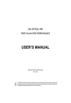
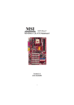
1
GA-8IAX
Pentium Prescott 800 Motherboard
USER’S MANUAL
Pentium®Prescott Processor Motherboard
Rev. 1001
12ME-8IAX-1001
English
GA-8IAX Motherboard
Table of Content
Item Checklist ......................................................................................... 4
WARNING! ............................................................................................... 4
Chapter 1 Introduction ............................................................................ 5
Features Summary ...................................................................................... 5
GA-8IAX Motherboard Layout ...................................................................... 7
Chapter 2 Hardware Installation Process ............................................... 9
Step 1: Installing Processor and CPU Haet Sink ...................................... 10
Step1-1: Installing CPU ................................................................................................... 10
Step1-2: Installing Heat Sink ............................................................................................ 11
Step 2: Install memory modules ................................................................ 12
Step 3: Install expansion cards ................................................................. 14
Step 4: Connect ribbon cables, cabinet wires, and power supply .......... 15
Step 4-1 : I/O Back Panel Introduction .......................................................................... 15
Step 4-2 :Connectors & Jumper Setting Introduction ................................................... 18
Chapter 3 BIOS Setup .......................................................................... 32
The Main Menu (For example: BIOS Ver. : D4)........................................ 33
Standard CMOS Features......................................................................... 35
Advanced BIOS Features .......................................................................... 38
Integrated Peripherals .............................................................................. 41
Power Management Setup ....................................................................... 46
PC Health Status........................................................................................ 48
Load Fail-Safe Defaults ............................................................................. 50
Load Optimized Defaults ........................................................................... 50
Set Supervisor/User Password .................................................................. 51
Save & Exit Setup ....................................................................................... 52
Exit Without Saving ................................................................................... 52
2
Chapter 4 Technical Reference ............................................................ 53
Block Diagram ........................................................................................... 53
Chapter 5 Driver Installation .................................................................. 54
A.Intel Chipset Software Installation Utility .................................................................... 54
B.Broadcom Network Driver Installation ....................................................................... 56
C.Realtek Audio Driver ................................................................................................... 57
D.DirectX 9.0 Driver Installation ...................................................................................... 58
E.Intel SATA Driver Installation ....................................................................................... 59
Chapter 6 Appendix .............................................................................. 61
Acronyms ....................................................................................................................... 61
3
English
Table of Content
English
GA-8IAX Motherboard
Item Checklist
The GA-8IAX motherboard
Serial ATA cable x 4
IDE (ATA133 ) cable x 1 / Floppy cable x 1
CD for motherboard driver & utility
I/O Shield
GA-8IAX user’s manual
WARNING!
Computer motherboards and expansion cards contain very delicate Integrated Circuit (IC) chips. To
protect them against damage from static electricity, you should follow some precautions whenever you
work on your computer.
1.
Unplug your computer when working on the inside.
2.
Use a grounded wrist strap before handling computer components. If you do not have
one, touch both of your hands to a safely grounded object or to a metal object, such as
the power supply case.
Hold components by the edges and try not touch the IC chips, leads or connectors, or
other components.
Place components on a grounded antistatic pad or on the bag that came with the
components whenever the components are separated from the system.
Ensure that the ATX power supply is switched off before you plug in or remove the ATX
3.
4.
5.
power connector on the motherboard.
Installing the motherboard to the chassis…
If the motherboard has mounting holes, but they don’t line up with the holes on the base and
there are no slots to attach the spacers, do not become alarmed you can still attach the spacers to
the mounting holes. Just cut the bottom portion of the spacers (the spacer may be a little hard to
cut off, so be careful of your hands). In this way you can still attach the motherboard to the base
without worrying about short circuits. Sometimes you may need to use the plastic springs to isolate
the screw from the motherboard PCB surface, because the circuit wire may be near by the hole. Be
careful, don’t let the screw contact any printed circuit write or parts on the PCB that are near the
fixing hole, otherwise it may damage the board or cause board malfunctioning.
4
Introduction
Chapter 1 Introduction
Features Summary
Form Factor
y
30.6cm x 24.4cm ATX size form factor, 6 layers PCB.
CPU
y
y
Supports Intel® Pentium Prescot LGA 775 processor
Intel® Prescot LGA 775 supports 800MHz FSB
Chipset
y
y
L2 cache on-die per processor from 1M
Intel® Alderwood 925X Chipset
Memory
y
y
Intel® ICH6R
4 x 240-pin DDRII DIMM sockets
y
y
Supports 4 ECC Un-buffered DIMM DDRII 400
Support 128MB, 256MB, 512MB, and 1GB memory
y
y
Single-bit Errors Correction, Multiple-bit Errors Detection
ITE IT8712F Super I/O
y
y
Supports 4 PCI slots 32-Bit/33MHz (5V)
Supports 1 PCI-E x16 slot
On-Board RAID
y
y
Supports 1 PCI-E x 1 slot
ICH6R
On-Board Peripherals
y
y
Supports SATA RAID 0,1
1 Floppy port supports 2 FDD with 360K, 720K,1.2M, 1.44M
y
and 2.88M bytes.
1 Parallel port supports Normal/EPP/ECP mode
y
y
1 Serial port (COM)
4 x USB 2.0 (2 by cable)
y
y
2 x IEEE 1394 ( 1 by cable)
1 x LAN RJ45
y
y
4 x SATA Connectors
CPU/Power/System Fan Revolution Detect
y
y
CPU shutdown when overheat
System Voltage Detect
On-Board LAN
On-Board USB 2.0
y
y
Broadcom 5751 Gigabit Ethernet (PCI-E)
Built in ICH6R Chipset
PS/2 Connector
BIOS
y
y
PS/2 Keyboard interface and PS/2 Mouse interace
Award BIOS on 4Mb flash RAM
I/O Control
Expansion Slots
Hardware Monitor
5
English
GA-8IAX Motherboard
Additional Features
y
PS/2 Mouse power on under Windows Operating System
y
y
External Modem wake up
Supports S1, S3, S4, S5 under Windows Operating System
y
y
Wake on LAN (WOL)
AC Recovery
y
Supports Console Redirection
6
Introduction
GA-8IAX Motherboard Layout
15
P
Q
3
F
2
12
BCM5751
F_
AUDIO_AC97
4
5
KB_
MS
PWR
_JP1
IR
6
COMA LPT
1
REAR
_F
AN
F_
AUDIO_ACZ
JP2
S_IRQ
V
NB_F
AN
1
CI
N
AL
C260
CD_IN
US
B_
1394
AL
C655
M
US
B_
LA
N2
1
18
17
COMB
RE
V1
:.0
ITE8712
16
14
13
CPU_F
AN
A
2
PCI
1
PCI
2
PCI
3
PCI
4
L
F_
US
B1
LGA77
5
D
PCI
_B
T
F_
1394
B
PCI
E_16
ALDERWOOD
1
PWR
_JP4
7
C
BC70
3
SN
R155
6
F_
US
B2
PWR
_JP3
8
DDR
II
3
DDR
II
4
9mm
9mm
1
9mm
1
7
1
9mm
9mm
IDE
E
FRO
NT_F
AN
XT
BAT
7
9mm
S_ATA1
F_
PANEL
S_ATA3
9mm
7
S_ATA2
S_ATA0
1
BATT
ER
Y
9mm
SCSI_LED
J
O
I
EC71
DDR
II
1
DDR
II
2
7
K
SYS_F
AN
U
FDD
W
S
9
G
H
ATX
7
11
ASS
EM:
PSU
_A
FN
Y
R
10
English
GA-8IAX Motherboard
A.
B.
C.
D.
CPU
Intel Alderwood 925X
Intel ICH6R
BIOS
1.
2.
3.
4.
PCIE_16 (x16)
PCIE_1 (x 4)
PCI_1
PCI_2
E.
F.
G.
H.
BAT (Li-Battery)
Broadcom 5751
IDE
FDD
5.
6
7.
8.
PCI_3
PCI_4
DDRII1
DDRII2
I.
J.
K.
L.
M.
N.
O.
P.
Q.
R.
S.
T.
U.
V.
W.
X
Y.
F_Panel (Front Panel)
9.
F_USB2 (Front USB)
10.
F_USB1 (Front USB)
11.
F_1394 (IEEE 1394)
12.
F_Audio_ACZ
13.
CI
14.
SCSI LED
15.
CD_IN
16.
ITE IT8712F
17.
SATA_0
18.
SATA_1
SATA_2
SATA_3
CPU_FAN (CPU Fan Connector)
SYS_FAN (System Fan Connector)
Front_FAN
PSU_FAN (Power Supply Fan)
8
DDRII3
DDRII4
ATX
ATX_12V
Audio
USB_LAN2
USB_1394
LPT
COMA
KB_MS (Keyboard and Mouse)
Hardware Installation Process
Chapter 2 Hardware Installation Process
To set up your computer, you must complete the following steps:
Step 1- Install the Central Processing Unit (CPU)
Step 2- Install memory modules
Step 3- Install expansion cards
Step 4- Connect ribbon cables, cabinet wires, and power supply
Step 5- Setup BIOS software
Step4
Step3
KB_
MS
1
PWR
_JP1
IR
BCM5751
F_
AUDIO_AC97
REAR
_F
AN
F_
AUDIO_ACZ
AL
C260
CD_IN
US
B_
1394
AL
C655
US
B_
LA
N2
1
ITE8712
COMA LPT
COMB
RE
V1
:.0
JP2
S_IRQ
NB_F
AN
CI
CPU_F
AN
Step1
F_
1394
PCI
_B
T
PCI
1
PCI
2
PCI
3
PCI
4
2
LGA77
5
F_
UB
S1
PCI
E_16
ALDERWOOD
1
PWR
_JP4
EC71
SN
R155
6
F_
UB
S2
DDR
II
1
DDR
II
2
BC70
3
PWR
_JP3
1
S_ATA1
IDE
ATX
7
1
9mm
9mm
9mm
9mm
1
BAT
7
S_ATA3
F_
PANEL
7
9mm
9mm
9mm
1
S_ATA0
7
S_ATA2
BATT
EY
R
9mm
SCSI_LED
DDR
II
3
DDR
II
4
ASS
EM:
FRO
NT_F
AN
SYS_F
AN
FDD
Step 4
Step 4
PSU
_F
AN
Step 4
Step 2
Step4
9
English
GA-8IAX Motherboard
Step 1: Installing Processor and CPU Haet Sink
Before installing the processor and cooling fan, adhere to the following cautions:
1. The processor will overheat without the heatsink and/or fan, resulting in permanent
irreparable damage.
2. Never force the processor into the socket.
3. Apply thermal grease on the processor before placing cooling fan.
4. Please make sure the CPU type is supported by the motherboard.
5. If you do not match the CPU socket Pin 1 and CPU cut edge well, it will cause improper
installation. Please change the insert orientation.
Step1-1: Installing CPU
Step 1 Gently lift the metal lever located on the CPU socket to the upper-right position.
Step 2 Remove the plastic covering on the CPU socket.
Step 3 Align the indented corner of the CPU with the triangle and gently insert the CPU into position.
(Grasping the CPU firmly between your thumb and forefinger, carefully place it into the socket
in a straight and downwards motion. Avoid twisting or bending motions that might cause
damage to the CPU during installation.)
Step 4 Once the CPU is properly inserted, please replace the plastic covering and push the metal
lever back into its original position.
Step 5 Close the lever, reverse step 1 & 2.
10
Hardware Installation Process
Step1-2: Installing Heat Sink
Male Push Pin
The top of Female Push Pin
Female Push Pin
Fig.1
Please apply heatsink paste on the surface of
the installed CPU.
Fig. 2
( to remove the heatsink, turning the push pin along
the direction of arrow; and reverse the previous
step to install the heat sink.)
Please note the direction of arrow sign on the male
push pin doesn't face inwards before installation.
(This instruction is only for Intel boxed fan)
Fig. 3
Place the heatsink on top the CPU and make
sure the push pins align to the pin hole on the
motherboard.Push down the push pins
diagonally.
Fig. 4
Please make sure the Male and Female push pin
are brought together. (for detailed installation
instructions, please refer to the heatsink installation
section of the user manual)
Fig. 5
Please check the back side of teh motherboard.
Make sure the push pin is seated firmly as the
picture shown. Installation completed.
Fig. 6
Attach the power connector of the heatsink to the
CPU fan header located on the motherboard.
11
Step 2: Install memory modules
Before installing the processor and heatsink, adhere to the following warning:
When DIMM LED is ON, do not install/remove DIMM from socket.
Please note that the DIMM module can only fit in one direction due to the one notches. Wrong
orientation will cause improper installation. Please change the insert orientation.
GA-8IAX has 4 dual inline memory module (DIMM) socets. It supports the Dual Channel Technology.
The BIOS will automatically detects memory type and size. To install the memory module, just push it
vertically into the DIMM socket .The DIMM module can only fit in one direction due to the notch. Memory
size can vary between sockets.
KB_
MS
1
PWR
_JP1
IR
BCM5751
F_
AUDIO_AC97
REAR
_F
AN
F_
AUDIO_ACZ
AL
C260
CD_IN
US
B_
1394
AL
C655
US
B_
LA
N2
1
ITE8712
COMA LPT
COMB
RE
V1
:.0
JP2
S_IRQ
CPU_F
AN
NB_F
AN
CI
F_
1394
PCI
_B
T
PCI
1
PCI
2
PCI
3
PCI
4
2
LGA77
5
F_
UB
S1
PCI
E_16
ALDERWOOD
1
PWR
_JP4
EC71
SN
R155
6
F_
UB
S2
DDR
II
1
DDR
II
2
BC70
3
PWR
_JP3
Channel A
BAT
IDE
ATX
F_
PANEL
1
7
1
9mm
9mm
9mm
7
S_ATA1
9mm
9mm
9mm
9mm
1
S_ATA3
7
S_ATA2
S_ATA0
1
Channel B
BATT
EY
R
9mm
SCSI_LED
DDR
II
3
DDR
II
4
7
English
GA-8IAX Motherboard
ASS
EM:
FRO
NT_F
AN
SYS_F
AN
FDD
PSU
_F
AN
Notch
DDRII
12
Hardware Installation Process
Installation Step:
1. The DIMM slot has a notch, so the DIMM memory module can only fit in one direction.
2. Insert the DIMM memory module vertically into the DIMM slot. Then push it down.
3. Close the plastic clip at both edges of theDIMM slots to lock the DIMM module.
4. When installing the DIMM into the DIMM module, we recommend to populate one DIMM in
Channel A module and one in Channel B module for best performance.
Please note that each logical DIMM must be madeof two identical DIMMs having the same
device size on each and the same DIMM size.
5. Reverse the installation steps when you wish to remove the DIMM module.
Notch
DDR DIMM Supported Configuration
# of R ow
# of C olumn
Adress B its Adress B its
# o f B an k
Adress B its
P ag e
Siz e
R an k
Siz e
9
2
4K
128MB
13
10
2
8K
256MB
32M x 8
13
10
2
8K
256MB
512Mbi t
64M x 8
13
11
2
16K
512MB
512Mbi t
64M x 8
14
10
2
8K
512MB
1Gbi t
64M x 16
14
10
2
8K
512MB
1Gbi t
128M x 8
14
11
2
16K
1GB
1Gbi t
64M x 16
13
10
3
8K
512MB
1Gbi t
128M x 8
14
10
3
8K
1GB
Technology
C onfiguration
256Mbi t
16M x 16
13
256Mbi t
32M x 8
512Mbi t
13
English
GA-8IAX Motherboard
Step 3: Install expansion cards
1. Read the related expansion card’s instruction document before install the expansion card into
the computer.
2. Remove your server’s chassis cover, necessary screws and slot bracket from the computer.
3. Press the expansion card firmly into expansion slot in motherboard.
4. Be sure the metal contacts on the card are indeed seated in the slot.
5. Replace the screw to secure the slot bracket of the expansion card.
6. Replace your computer’s chassis cover.
7. Power on the computer, if necessary, setup BIOS utility of expansion card from BIOS.
8. Install related driver from the operating system.
Please carefully pull out the small whitedrawable bar at the end of the
PCI Express x 4 slot when you try to
install/Uninstall the VGA card. Please align
the VGA card to the onboard
PCI Express x 4 slot and fully seated.
Make sure your VGA card is locked by
the small white-drawable bar.
14
1
CD_IN
AL
C260
AL
C655
PWR
_JP1
^
]
F_
AUDIO_ACZ
_
F_
AUDIO_AC97
REAR
_F
AN
IR
S_IRQ
CPU_F
AN
CI
NB_F
AN
PCI
4
PCI
3
PCI
2
PCI
1
F_
1394
LGA77
5
PCI
E_16
ALDERWOOD
F_
UB
S1
EC71
1
S
N
PWR
_JP4
BC70
3
DDR
II
1
DDR
II
2
F_
UB
S2
PWR
_JP3
DDR
II
3
DDR
II
4
SCSI_LED
IDE
S_ATA2
S_ATA0
BATT
EY
R
BAT
S_ATA1
ASS
EM:
F_
PANEL
S_ATA3
PSU
_A
FN
FDD
SYS_F
AN
FRO
NT_F
AN
US
BL
_N
A2
PCI
_T
B
1
US
B1
_394
9mm
9mm
RE
V1
:.0
COMB
1
COMA LPT
7
ITE8712
ATX
9mm
9mm
9mm
15
9mm
\
1
Z
1
7
[
9mm
9mm
Y
2
1
BCM5751
X
7
7
R155
6
KB_
MS
Hardware Installation Process
Step 4: Connect ribbon cables, cabinet wires, and power
supply
Step 4-1 : I/O Back Panel Introduction
JP2
English
GA-8IAX Motherboard
X PS/2 Keyboard and PS/2 Mouse Connector
To install a PS/2 port keyboard and mouse, plug the mouse to the upper port (green) and the keyboard
to the lower port (purple).
Y/Z Parallel Port / Serial Port
This connector supports 1 standard COM port and 1 Parallel port. Device like printer can be
connected to Parallel port ; mouse and modem etc can be connected to Serial port.
[ IEEE 1394 Port
Connects the IEEE1394 devices to this connector.
\/] USB port
Before you connect your device(s) into USB connector(s), please make sure your device(s) such
as USB keyboard, mouse, scanner, zip, speaker...etc. have a standard USB interface.
Also make sure your OS supports USB controller. If your OS does not support USB controller,
please contact OS vendor for possible patch or driver upgrade. For more information please
contact your OS or device(s) vendors.
^ LAN Port
The provided Internet connection is Gigabit Ethernet, providing data transfer speeds of 10/100/
1000Mbps.
LAN LED Description
Name
Color
LAN
Green
Link/Activity Green
Condition
ON
Description
LAN Link / no Access
BLINK
OFF
LAN Access
Idle
ON
OFF
100Mbps connection
10Mbps connection
ON
BLINK
1Gbps connection
Port identification with 1Gbps connection
Green
Green
ON
BLINK
100Mbps connection
Port identification with 10 or 100Mbps connection
-
OFF
10Mbps connection
10/100 LAN Green
Speed
GbE LAN Yellow
Speed
Yellow
16
Hardware Installation Process
_ Audio Connector
Line Out
(Front Speaker)
Line In
(Rear Speaker)
MIC In
(Center and Subwoofer)
After install onboard audio driver, you may connect
speaker to Line Out jack, micro phone to MIC In jack.
Device like CD-ROM , walkman etc can be connected
to Line-In jack.
Please note:
You are able to use 2-/4-/6- channel audio feature by
S/W selection.
If you want to enable 6-channel function, you have 2
choose for hardware connection.
Method1:
Connect “Front Speaker” to “Line Out”
Connect “Rear Speaker” to “Line In”
Connect “Center and Subwooferr” to “MIC In “.
17
Step 4-2 :Connectors & Jumper Setting Introduction
4B
P
KB_
MS
3
1
PWR
_JP1
IR
BCM5751
F_
AUDIO_AC97
REAR
_F
AN
F_
AUDIO_ACZ
AL
C260
CD_IN
US
B_
1394
AL
C655
ITE8712
US
B_
LA
N2
1
O
COMA LPT
COMB
RE
V:
1.0
JP2
S_IRQ
PCI
_B
T
PCI
1
PCI
2
PCI
3
PCI
4
PCI
E_16
ALDERWOOD
1
EC71
S
N
DDR
II
1
DDR
II
2
R155
6
F_
UB
S2
BC70
3
PWR
_JP3
DDR
II
3
DDR
II
4
9mm
1
9mm
9mm
1
1
S_ATA1
F_
PANEL
S_ATA3
9mm
7
BAT
IDE
M
C
ATX
7
9mm
9mm
1
7
S_ATA2
S_ATA0
9mm
BATT
EY
R
L
9mm
SCSI_LED
K
ASS
EM:
FRO
NT_F
AN
5 T G
H
A)
B)
C)
D)
E)
F)
G)
H)
I)
J)
K)
L)
M)
N)
LGA77
5
J
PWR
_JP4
Q
F_
UB
S1
6
2
F_
1394
I
R
CPU_F
AN
NB_F
AN
CI
N
7
English
GA-8IAX Motherboard
SYS_F
AN
2 1
F
E
PSU
_F
AN
FDD
D
S
ATX1
ATX 12V
IDE
FDD
SATA_0
SATA_1
SATA_2
SATA_3
F_1394
F_USB2
F_USB1
F_Panel
BAT
CI
18
U
A
O)
P)
Q)
R)
S)
T)
U)
F_AUDIO_ACZ
CD_IN
SCSI_LED
CPU_FAN
SYS_FAN
FRONT_FAN
PSU_FAN
1)
2)
3)
4)
5)
6)
JP1
JP3
PWR_JP1
PWR_JP2
PWR_JP3
PWR_JP4
Connector Introduction
A) ATX (ATX Power Connector)
12
24
1
13
KB_
MS
AL
C260
PWR
_JP1
BCM5751
F_
AUDIO_AC97
IR
JP2
S_IRQ
CPU_F
AN
NB_F
AN
CI
PCI
3
F_
1394
PCI
_B
T
PCI
1
PCI
2
PCI
4
2
LGA77
5
F_
US
B1
PCI
E_16
ALDERWOOD
1
PWR
_JP4
EC71
SN
DDR
II
1
DDR
II
2
R155
6
F_
US
B2
PIN No.
Definition
1
+3.3V
2
3
+3.3V
GND
4
5
+5V
GND
6
7
+5V
GND
8
9
POK
5VSB
10
11
+12V
+12V
12
13
+3.3V
+3.3V
14
15
-12V
GND
16
17
PSON
GND
18
19
GND
GND
20
21
-5V
+5V
22
23
+5V
+5V
24
GND
1
REAR
_F
AN
F_
AUDIO_ACZ
US
B_
LA
N2
AL
C655
CD_IN
US
B_
1394
1
ITE8712
COMA LPT
COMB
RE
V:
1.0
BC70
3
PWR
_JP3
9mm
9mm
9mm
1
1
S_ATA3
S_ATA1
BAT
IDE
F_
PANEL
9mm
7
1
9mm
ATX
7
1
9mm
7
S_ATA0
7
S_ATA2
9mm
BATT
ER
Y
9mm
SCSI_LED
DDR
II
3
DDR
II
4
ASS
EM:
FRO
NT_F
AN
SYS_F
AN
PSU
_F
AN
FDD
AC power cord should only be connected to
your power supply unit after ATX power cable
and other related devices are firmly connected
to the mainboard.
B ) ATX_12V( +12V Power Connector)
KB_
MS
AL
C260
1
PWR
_JP1
IR
BCM5751
F_
AUDIO_AC97
REAR
_F
AN
F_
AUDIO_ACZ
US
B_
LA
N2
AL
C655
CD_IN
US
B_
1394
1
ITE8712
COMA LPT
COMB
RE
V:
1.0
JP2
S_IRQ
NB_F
AN
CI
CPU_F
AN
PCI
3
F_
1394
PCI
_B
T
PCI
1
PCI
2
PCI
4
2
LGA77
5
F_
US
B1
PCI
E_16
ALDERWOOD
1
PWR
_JP4
SN
R155
6
F_
US
B2
1
EC71
DDR
II
1
DDR
II
2
BC70
3
PWR
_JP3
9mm
9mm
9mm
9mm
9mm
ATX
1
1
IDE
7
F_
PANEL
7
9mm
9mm
1
1
S_ATA1
BAT
7
S_ATA3
7
S_ATA2
S_ATA0
BATT
ER
Y
9mm
SCSI_LED
DDR
II
3
DDR
II
4
ASS
EM:
FRO
NT_F
AN
SYS_F
AN
FDD
PSU
_F
AN
This connector (ATX +12V) is used only for
CPU1 Core Voltage.
19
Pin No.
1
2
3
4
Definition
GND
GND
P12V-CPU0
P12V-CPU0
Please connect first harddisk to IDE1. The red stripe of the ribbon cable must be the same side with
the Pin1.
40
2
KB_
MS
AL
C260
1
PWR
_JP1
IR
BCM5751
F_
AUDIO_AC97
REAR
_F
AN
F_
AUDIO_ACZ
US
B_
LA
N2
AL
C655
CD_IN
US
B_
1394
1
ITE8712
COMA LPT
COMB
RE
V:
1.0
JP2
S_IRQ
1
CPU_F
AN
NB_F
AN
CI
39
IDE
PCI
3
F_
1394
PCI
_B
T
PCI
1
PCI
2
PCI
4
2
LGA77
5
F_
US
B1
PCI
E_16
ALDERWOOD
1
PWR
_JP4
EC71
SN
R155
6
F_
US
B2
DDR
II
1
DDR
II
2
BC70
3
PWR
_JP3
9mm
9mm
9mm
1
1
S_ATA3
S_ATA1
BAT
IDE
F_
PANEL
9mm
7
1
9mm
ATX
7
1
9mm
7
S_ATA0
7
S_ATA2
9mm
BATT
ER
Y
9mm
SCSI_LED
DDR
II
3
DDR
II
4
ASS
EM:
FRO
NT_F
AN
SYS_F
AN
PSU
_F
AN
FDD
D) FDD (Floppy Connector)
Please connect the floppy drive ribbon cables to FDD. It supports 360K,720K,1.2M,1.44M and
2.88Mbytes floppy disk types. The red stripe of the ribbon cable must be the same side with the
Pin1.
KB_
MS
AL
C260
1
PWR
_JP1
IR
BCM5751
F_
AUDIO_AC97
REAR
_F
AN
F_
AUDIO_ACZ
US
B_
LA
N2
AL
C655
CD_IN
US
B_
1394
1
ITE8712
COMA LPT
COMB
RE
V:
1.0
34
2
33
1
JP2
S_IRQ
NB_F
AN
CI
CPU_F
AN
PCI
3
F_
1394
PCI
_B
T
PCI
1
PCI
2
PCI
4
2
LGA77
5
F_
US
B1
PCI
E_16
ALDERWOOD
1
PWR
_JP4
EC71
SN
R155
6
F_
US
B2
DDR
II
1
DDR
II
2
BC70
3
PWR
_JP3
9mm
9mm
9mm
9mm
ATX
1
9mm
IDE
F_
PANEL
7
1
9mm
9mm
1
1
S_ATA1
BAT
7
S_ATA3
7
S_ATA2
S_ATA0
BATT
ER
Y
9mm
SCSI_LED
DDR
II
3
DDR
II
4
7
English
GA-8IAX Motherboard
C ) IDE Connector
ASS
EM:
FRO
NT_F
AN
SYS_F
AN
FDD
PSU
_F
AN
20
Connector Introduction
E / F/ G / H ) SATA_0/ 1/ 2/ 3 (Serial ATA Connectors)
You can connect the Serial ATA device to this connector, it provides you high speed transfer rates
(150MB/sec).
KB_
MS
AL
C260
1
PWR
_JP1
IR
BCM5751
F_
AUDIO_AC97
REAR
_F
AN
F_
AUDIO_ACZ
US
B_
LA
N2
AL
C655
CD_IN
US
B_
1394
1
ITE8712
COMA LPT
COMB
RE
V:
1.0
7
JP2
S_IRQ
NB_F
AN
CI
PCI
3
F_
1394
PCI
_B
T
PCI
1
PCI
2
PCI
4
2
Pin No.
1
2
3
4
5
6
7
CPU_F
AN
LGA77
5
F_
US
B1
PCI
E_16
ALDERWOOD
1
PWR
_JP4
EC71
SN
R155
6
F_
US
B2
DDR
II
1
DDR
II
2
BC70
3
PWR
_JP3
1
9mm
9mm
9mm
1
1
S_ATA3
S_ATA1
BAT
IDE
F_
PANEL
9mm
7
1
9mm
ATX
7
1
9mm
7
S_ATA0
7
S_ATA2
9mm
BATT
ER
Y
9mm
SCSI_LED
DDR
II
3
DDR
II
4
Definition
GND
TXP
TXN
GND
RXN
RXP
GND
ASS
EM:
FRO
NT_F
AN
SYS_F
AN
PSU
_F
AN
FDD
SATA_1
SATA_2
SATA_0
SATA_3
I ) F_1394(Front IEEE 1394 Connector)
KB_
MS
AL
C260
1
1
PWR
_JP1
IR
BCM5751
F_
AUDIO_AC97
REAR
_F
AN
F_
AUDIO_ACZ
US
B_
LA
N2
AL
C655
CD_IN
US
B_
1394
1
ITE8712
COMA LPT
COMB
RE
V:
1.0
JP2
S_IRQ
NB_F
AN
CI
CPU_F
AN
PCI
3
F_
1394
PCI
_B
T
PCI
1
PCI
2
PCI
4
2
LGA77
5
F_
US
B1
PCI
E_16
ALDERWOOD
1
PWR
_JP4
EC71
SN
R155
6
F_
US
B2
DDR
II
1
DDR
II
2
BC70
3
PWR
_JP3
9mm
9mm
9mm
9mm
9mm
ATX
1
1
IDE
7
F_
PANEL
7
9mm
9mm
1
1
S_ATA1
BAT
7
S_ATA3
7
S_ATA2
S_ATA0
BATT
ER
Y
9mm
SCSI_LED
DDR
II
3
DDR
II
4
ASS
EM:
FRO
NT_F
AN
SYS_F
AN
FDD
PSU
_F
AN
21
Pin No.
1
2
3
4
5
6
7
8
9
10
Definition
VCC
VCC
FTPA1+
FTPA1GND
GND
FTPB1+
FTPB1GND
Pin Removed
J) F_USB1 (Front USB1 Connector)
Be careful with the polarity of the front panel USB connector. Check the pin assignment while you
connect the front panel USB cable. Please contact your nearest dealer for optional front panel
USB cable.
1 2
KB_
MS
AL
C260
1
F_
AUDIO_AC97
REAR
_F
AN
F_
AUDIO_ACZ
US
B_
LA
N2
AL
C655
CD_IN
US
B_
1394
1
ITE8712
COMA LPT
COMB
RE
V:
1.0
PWR
_JP1
BCM5751
IR
JP2
S_IRQ
CPU_F
AN
NB_F
AN
CI
9 10
PCI
1
PCI
3
PCI
2
PCI
4
2
Pin No.
1
2
3
4
5
6
7
8
9
10
PCI
_B
T
F_
1394
LGA77
5
F_
US
B1
PCI
E_16
ALDERWOOD
1
PWR
_JP4
EC71
SN
R155
6
F_
US
B2
DDR
II
1
DDR
II
2
BC70
3
PWR
_JP3
9mm
9mm
1
9mm
1
S_ATA1
BAT
IDE
F_
PANEL
7
1
9mm
9mm
ATX
7
1
9mm
7
S_ATA3
7
S_ATA2
S_ATA0
9mm
BATT
ER
Y
9mm
SCSI_LED
DDR
II
3
DDR
II
4
ASS
EM:
FRO
NT_F
AN
SYS_F
AN
PSU
_F
AN
FDD
Definition
USB3_OC#2_FB (USB power)
USB3_OC#2_FB(USB power)
USB_ICH_P4N_IND
USB_ICH_P5N_IND
USB_ICH_P4P_IND
USB_ICH_P5P_IND
GND
GND
PIN Removed
NC
K )F_USB2 (Front USB2 Connector)
1 2
KB_
MS
AL
C260
1
PWR
_JP1
IR
BCM5751
F_
AUDIO_AC97
REAR
_F
AN
F_
AUDIO_ACZ
US
B_
LA
N2
AL
C655
CD_IN
US
B_
1394
1
ITE8712
COMA LPT
COMB
RE
V:
1.0
JP2
S_IRQ
CPU_F
AN
NB_F
AN
CI
PCI
3
F_
1394
PCI
_B
T
PCI
1
PCI
2
PCI
4
2
LGA77
5
F_
US
B1
PCI
E_16
PWR
_JP4
EC71
SN
DDR
II
1
DDR
II
2
R155
6
F_
US
B2
11 12
ALDERWOOD
1
BC70
3
PWR
_JP3
Pin No.
1
2
3
4
5
6
7
8
9
10
11
12
9mm
9mm
9mm
9mm
ATX
1
9mm
IDE
F_
PANEL
7
1
9mm
9mm
1
1
S_ATA1
BAT
7
S_ATA3
7
S_ATA2
S_ATA0
BATT
ER
Y
9mm
SCSI_LED
DDR
II
3
DDR
II
4
7
English
GA-8IAX Motherboard
ASS
EM:
FRO
NT_F
AN
SYS_F
AN
FDD
PSU
_F
AN
22
Definition
Pin Removed
NC
USB4_OC#3_FB(USB power)
USB4_OC#3_FB(USB power)
USB_ICH_P6N_IND
USB_ICH_P7N_IND
USB_ICH_P6P_IND
USB_ICH_P7P_IND
GND
GND
Pin Removed
N/C
Connector Introduction
L ) F_Panel (2X10 Pins connector)
Please connect the power LED, PC speaker, reset switch and power switch of your chassis
front panel to the F_PANEL connector according to the pin assignment above.
KB_
MS
AL
C260
PWR
_JP1
IR
BCM5751
F_
AUDIO_AC97
12
1
REAR
_F
AN
F_
AUDIO_ACZ
US
B_
LA
N2
AL
C655
CD_IN
US
B_
1394
1
ITE8712
COMA LPT
COMB
RE
V:
1.0
JP2
S_IRQ
NB_F
AN
CI
CPU_F
AN
PCI
3
F_
1394
PCI
_B
T
PCI
1
PCI
2
PCI
4
2
LGA77
5
F_
US
B1
PCI
E_16
ALDERWOOD
1
PWR
_JP4
EC71
SN
19 20
R155
6
F_
US
B2
DDR
II
1
DDR
II
2
BC70
3
PWR
_JP3
9mm
S_ATA1
9mm
9mm
9mm
9mm
ATX
1
1
IDE
7
F_
PANEL
7
9mm
9mm
1
1
S_ATA3
BAT
7
S_ATA0
7
S_ATA2
BATT
ER
Y
9mm
SCSI_LED
DDR
II
3
DDR
II
4
ASS
EM:
FRO
NT_F
AN
SYS_F
AN
Pin No
1
FDD
PSU
_F
AN
Signal Name
HD+
Description
Hard Disk LED anode (+)
2
3
MSG+
HD-
MESSAGE signal anode (+)
4
5
MSGRES-
MESSAGE signal cathode(-)
6
7
PW+
RES+
Soft power connector anode (+)
Front Panel Reset Switch anode (+)
8
9
PWNC
Soft power connector cathode(-)
No connect
10
11
Pin Removed
Pin Removed
NC
NC
12
13
Pin Removed
GD+
NC
Green LED anode (+)
14
15
SPK+
GD-
Speaker connector anode (+)
Green LED cathode(-)
16
17
SPK+
GN+
Speaker connector cathode(-)
Green Switch anode (+)
18
19
SPKGN-
Speaker connector anode (+)
Green Switch cathode(-)
20
SPK-
Speaker connector cathode(-)
Hard Disk LED cathode(-)
Front Panel Reset Switch cathode(-)
23
M ) BAT (Battery)
1
PWR
_JP1
IR
BCM5751
F_
AUDIO_AC97
REAR
_F
AN
F_
AUDIO_ACZ
AL
C260
CD_IN
KB_
MS
AL
C655
US
B_
LA
N2
1
ITE8712
COMA LPT
COMB
RE
V:
1.0
US
B_
1394
JP2
S_IRQ
NB_F
AN
CI
CPU_F
AN
PCI
3
F_
1394
PCI
_B
T
PCI
1
PCI
2
PCI
4
2
LGA77
5
F_
US
B1
PCI
E_16
CAUTION
ALDERWOOD
1
PWR
_JP4
EC71
SN
Danger of explosion if battery is incorrectly
R155
6
F_
US
B2
DDR
II
1
DDR
II
2
BC70
3
PWR
_JP3
BAT
9mm
9mm
9mm
1
1
replaced.
Replace only with the same or equivalent
9mm
ATX
1
1
9mm
7
IDE
7
7
S_ATA1
F_
PANEL
S_ATA3
9mm
7
S_ATA0
S_ATA2
9mm
BATT
ER
Y
9mm
SCSI_LED
DDR
II
3
DDR
II
4
ASS
EM:
FRO
NT_F
AN
SYS_F
AN
PSU
_F
AN
FDD
type recommended by the manufacturer.
Dispose of used batteries according to the
BAT
manufacturer’s instructions.
If you want to erase CMOS...
1.Turn OFF the computer and unplug the power cord.
2.Remove the battery, wait for 30 second.
3.Re-install the battery.
4.Plug the power cord and turn ON the computer.
N) CI (CASE OPEN)
This 3 pin connector allows your system to enable or disable the “case open” item in BIOS
if the system case begin remove.
KB_
MS
AL
C260
1
PWR
_JP1
IR
BCM5751
F_
AUDIO_AC97
REAR
_F
AN
F_
AUDIO_ACZ
US
B_
LA
N2
AL
C655
CD_IN
US
B_
1394
1
ITE8712
COMA LPT
COMB
RE
V:
1.0
JP2
S_IRQ
CPU_F
AN
NB_F
AN
CI
PCI
3
F_
1394
PCI
_B
T
PCI
1
PCI
2
PCI
4
2
1
LGA77
5
F_
US
B1
PCI
E_16
ALDERWOOD
1
PWR
_JP4
EC71
SN
R155
6
F_
US
B2
DDR
II
1
DDR
II
2
BC70
3
PWR
_JP3
9mm
9mm
9mm
9mm
ATX
1
9mm
IDE
F_
PANEL
7
1
9mm
9mm
1
1
S_ATA1
BAT
7
S_ATA3
7
S_ATA2
S_ATA0
BATT
ER
Y
9mm
SCSI_LED
DDR
II
3
DDR
II
4
7
English
GA-8IAX Motherboard
ASS
EM:
FRO
NT_F
AN
SYS_F
AN
FDD
PSU
_F
AN
24
Pin No.
1
2
3
Definition
GND
INTRUDER#
NC
Connector Introduction
O) F_Audio_ACZ (Front Audio connector)
If you want to use Front Audio connector, you must remove 5-6, 9-10 Jumper. In order to utilize the
front audio header, your chassis must have front audio connector. Also please make sure the pin
assigment on the cable is the same as the pin assigment on the MB header. To find out if the chassis
you are buying support front audio connector, please contact your dealer.
KB_
MS
AL
C260
1
PWR
_JP1
IR
BCM5751
F_
AUDIO_AC97
REAR
_F
AN
F_
AUDIO_ACZ
US
B_
LA
N2
AL
C655
CD_IN
US
B_
1394
1
ITE8712
COMA LPT
COMB
RE
V:
1.0
JP2
S_IRQ
12
NB_F
AN
CI
CPU_F
AN
PCI
3
F_
1394
PCI
_B
T
PCI
1
PCI
2
PCI
4
2
LGA77
5
F_
US
B1
PCI
E_16
9 10
ALDERWOOD
1
PWR
_JP4
EC71
SN
R155
6
F_
US
B2
DDR
II
1
DDR
II
2
BC70
3
PWR
_JP3
9mm
9mm
9mm
1
1
S_ATA3
S_ATA1
BAT
IDE
Definition
MIC2_L
GND
MIC2_R
ACZ_DET
HP_OUTL_R
FAUDIO_JD
GND
No Pin
HP_OUTL_L
HP_DET
F_
PANEL
9mm
7
1
9mm
ATX
7
1
9mm
7
S_ATA0
7
S_ATA2
9mm
BATT
ER
Y
9mm
SCSI_LED
DDR
II
3
DDR
II
4
Pin No.
1
2
3
4
5
6
7
8
9
10
ASS
EM:
FRO
NT_F
AN
SYS_F
AN
PSU
_F
AN
FDD
P) CD_IN1 (CD IN,Black)
KB_
MS
AL
C260
1
PWR
_JP1
IR
BCM5751
F_
AUDIO_AC97
REAR
_F
AN
F_
AUDIO_ACZ
US
B_
LA
N2
AL
C655
CD_IN
US
B_
1394
1
ITE8712
COMA LPT
COMB
RE
V:
1.0
JP2
S_IRQ
NB_F
AN
CI
CPU_F
AN
PCI
3
F_
1394
PCI
_B
T
PCI
1
PCI
2
PCI
4
2
LGA77
5
F_
US
B1
PCI
E_16
PWR
_JP4
EC71
SN
DDR
II
1
DDR
II
2
R155
6
F_
US
B2
1
ALDERWOOD
1
BC70
3
PWR
_JP3
9mm
9mm
9mm
9mm
9mm
ATX
1
1
IDE
7
F_
PANEL
7
9mm
9mm
1
1
S_ATA1
BAT
7
S_ATA3
7
S_ATA2
S_ATA0
BATT
ER
Y
9mm
SCSI_LED
DDR
II
3
DDR
II
4
ASS
EM:
FRO
NT_F
AN
SYS_F
AN
FDD
PSU
_F
AN
25
Pin No.
1
2
3
4
Definition
CD-L
GND
GND
CD_R
Q) SCSI_LED (SCSI Indicative LED Connector)
You can connect the SCSI indicative LED of your SCSI add-on card to this connector, which can
indicate whether the SCSI device is active or not.
KB_
MS
AL
C260
1
PWR
_JP1
IR
BCM5751
F_
AUDIO_AC97
REAR
_F
AN
F_
AUDIO_ACZ
US
B_
LA
N2
AL
C655
CD_IN
US
B_
1394
1
ITE8712
COMA LPT
COMB
RE
V:
1.0
JP2
S_IRQ
NB_F
AN
CI
PCI
3
F_
1394
PCI
_B
T
PCI
1
PCI
2
PCI
4
2
1
CPU_F
AN
LGA77
5
F_
US
B1
PCI
E_16
ALDERWOOD
1
PWR
_JP4
Pin No.
1
2
3
4
Definition
GND
SCSI_CONN_LED#
SCSI_CONN_LED#
GND
EC71
SN
R155
6
F_
US
B2
DDR
II
1
DDR
II
2
BC70
3
PWR
_JP3
9mm
9mm
9mm
1
1
S_ATA3
S_ATA1
BAT
IDE
F_
PANEL
9mm
7
1
9mm
ATX
7
1
9mm
7
S_ATA0
7
S_ATA2
9mm
BATT
ER
Y
9mm
SCSI_LED
DDR
II
3
DDR
II
4
ASS
EM:
FRO
NT_F
AN
SYS_F
AN
PSU
_F
AN
FDD
R ) CPU_FAN (CPU Fan Connector)
Please note, a proper installation of the CPU cooler is essential to prevent the CPU from running
under abnormal condition or damaged by overheating.The CPU fan connector supports Max. current
up to 1A .
KB_
MS
AL
C260
1
PWR
_JP1
IR
BCM5751
F_
AUDIO_AC97
REAR
_F
AN
F_
AUDIO_ACZ
US
B_
LA
N2
AL
C655
CD_IN
US
B_
1394
1
ITE8712
COMA LPT
COMB
RE
V:
1.0
JP2
S_IRQ
NB_F
AN
CI
CPU_F
AN
PCI
3
PCI
1
PCI
2
PCI
4
2
PCI
_B
T
F_
1394
1
LGA77
5
F_
US
B1
PCI
E_16
ALDERWOOD
1
PWR
_JP4
EC71
SN
R155
6
F_
US
B2
DDR
II
1
DDR
II
2
BC70
3
PWR
_JP3
9mm
9mm
9mm
9mm
ATX
1
9mm
IDE
F_
PANEL
7
1
9mm
9mm
1
1
S_ATA1
BAT
7
S_ATA3
7
S_ATA2
S_ATA0
BATT
ER
Y
9mm
SCSI_LED
DDR
II
3
DDR
II
4
7
English
GA-8IAX Motherboard
ASS
EM:
FRO
NT_F
AN
SYS_F
AN
FDD
PSU
_F
AN
26
Pin No.
1
2
3
4
Definition
GND
12V
Sense
Control
Connector Introduction
S ) SYS_FAN (System Fan Connector)
This connector allows you to link with the cooling fan on the system case to lower the system
temperature.
KB_
MS
AL
C260
1
PWR
_JP1
IR
BCM5751
F_
AUDIO_AC97
REAR
_F
AN
F_
AUDIO_ACZ
US
B_
LA
N2
AL
C655
CD_IN
US
B_
1394
1
ITE8712
COMA LPT
COMB
RE
V:
1.0
JP2
S_IRQ
NB_F
AN
CI
PCI
3
F_
1394
Pin No.
1
2
3
Definition
GND
+12V
Sense
PCI
_B
T
PCI
1
PCI
2
PCI
4
2
1
CPU_F
AN
LGA77
5
F_
US
B1
PCI
E_16
ALDERWOOD
1
PWR
_JP4
EC71
SN
R155
6
F_
US
B2
DDR
II
1
DDR
II
2
BC70
3
PWR
_JP3
9mm
9mm
9mm
1
1
S_ATA3
S_ATA1
BAT
IDE
F_
PANEL
9mm
7
1
9mm
ATX
7
1
9mm
7
S_ATA0
7
S_ATA2
9mm
BATT
ER
Y
9mm
SCSI_LED
DDR
II
3
DDR
II
4
ASS
EM:
FRO
NT_F
AN
SYS_F
AN
PSU
_F
AN
FDD
T) FRONT FAN (Front Fan Connector)
This connector allows you to link with the cooling fan on the system case to lower the system
temperature.
KB_
MS
AL
C260
1
PWR
_JP1
IR
BCM5751
F_
AUDIO_AC97
REAR
_F
AN
F_
AUDIO_ACZ
US
B_
LA
N2
AL
C655
CD_IN
US
B_
1394
1
ITE8712
COMA LPT
COMB
RE
V:
1.0
JP2
S_IRQ
NB_F
AN
CI
PCI
3
F_
1394
PCI
_B
T
PCI
1
PCI
2
PCI
4
2
1
CPU_F
AN
LGA77
5
F_
US
B1
PCI
E_16
ALDERWOOD
1
PWR
_JP4
EC71
SN
R155
6
F_
US
B2
DDR
II
1
DDR
II
2
BC70
3
PWR
_JP3
9mm
9mm
9mm
9mm
9mm
ATX
1
1
IDE
7
F_
PANEL
7
9mm
9mm
1
1
S_ATA1
BAT
7
S_ATA3
7
S_ATA2
S_ATA0
BATT
ER
Y
9mm
SCSI_LED
DDR
II
3
DDR
II
4
ASS
EM:
FRO
NT_F
AN
SYS_F
AN
FDD
PSU
_F
AN
27
Pin No.
1
2
3
Definition
GND
FAN_Power(+12V)
FAN_TACH
U ) PSU_FAN (Power Fan Connector)
This connector allows you to link with the cooling fan on the system case to lower the system
temperature.
KB_
MS
AL
C260
1
PWR
_JP1
IR
BCM5751
F_
AUDIO_AC97
REAR
_F
AN
F_
AUDIO_ACZ
US
B_
LA
N2
AL
C655
CD_IN
US
B_
1394
1
ITE8712
COMA LPT
COMB
RE
V:
1.0
JP2
S_IRQ
NB_F
AN
CI
CPU_F
AN
PCI
3
PCI
_B
T
F_
1394
1
PCI
1
PCI
2
PCI
4
2
LGA77
5
F_
US
B1
PCI
E_16
ALDERWOOD
1
PWR
_JP4
EC71
SN
R155
6
F_
US
B2
DDR
II
1
DDR
II
2
BC70
3
PWR
_JP3
9mm
S_ATA1
9mm
9mm
9mm
ATX
1
9mm
IDE
F_
PANEL
7
1
9mm
9mm
1
1
S_ATA3
BAT
7
S_ATA0
7
S_ATA2
BATT
ER
Y
9mm
SCSI_LED
DDR
II
3
DDR
II
4
7
English
GA-8IAX Motherboard
ASS
EM:
FRO
NT_F
AN
SYS_F
AN
FDD
PSU
_F
AN
28
Pin No.
1
Definition
GND
2
3
+12V
Sense
Connector Introduction
1) JP1 (Password Skip Function)
KB_
MS
AL
C260
1
PWR
_JP1
IR
BCM5751
F_
AUDIO_AC97
REAR
_F
AN
F_
AUDIO_ACZ
US
B_
LA
N2
AL
C655
CD_IN
US
B_
1394
1
ITE8712
COMA LPT
COMB
RE
V:
1.0
JP2
S_IRQ
NB_F
AN
CI
PCI
3
PCI
1
PCI
2
PCI
4
2
1
1-2 close: Normal (Default)
1
2-3 close: Skip Supervisor Password in
CPU_F
AN
BIOS setup menu
PCI
_B
T
F_
1394
LGA77
5
F_
US
B1
PCI
E_16
ALDERWOOD
1
PWR
_JP4
EC71
SN
R155
6
F_
US
B2
DDR
II
1
DDR
II
2
BC70
3
PWR
_JP3
9mm
9mm
9mm
1
1
S_ATA3
S_ATA1
BAT
IDE
F_
PANEL
9mm
7
1
9mm
ATX
7
1
9mm
7
S_ATA0
7
S_ATA2
9mm
BATT
ER
Y
9mm
SCSI_LED
DDR
II
3
DDR
II
4
ASS
EM:
FRO
NT_F
AN
SYS_F
AN
PSU
_F
AN
FDD
2) JP3 (Clear CMOS Function)
You may clear the CMOS data to its default values by this jumper.
Default value doesn’t include the “Shunter” to prevent from improper use this jumper. To
clear CMOS, temporarily short 1-2 pin.
KB_
MS
AL
C260
1
PWR
_JP1
IR
BCM5751
F_
AUDIO_AC97
REAR
_F
AN
F_
AUDIO_ACZ
US
B_
LA
N2
AL
C655
CD_IN
US
B_
1394
1
ITE8712
COMA LPT
COMB
RE
V:
1.0
JP2
1-2 close: Normal (Default vaule)
1
2-3 close: Clear CMOS
S_IRQ
1
NB_F
AN
CI
CPU_F
AN
PCI
3
F_
1394
PCI
_B
T
PCI
1
PCI
2
PCI
4
2
LGA77
5
F_
US
B1
PCI
E_16
ALDERWOOD
1
PWR
_JP4
EC71
SN
R155
6
F_
US
B2
DDR
II
1
DDR
II
2
BC70
3
PWR
_JP3
9mm
9mm
9mm
9mm
9mm
1
1
ATX
7
F_
PANEL
7
9mm
9mm
1
1
S_ATA1
IDE
7
S_ATA3
7
S_ATA2
S_ATA0
BATT
ER
Y
9mm
SCSI_LED
DDR
II
3
DDR
II
4
BAT
ASS
EM:
FRO
NT_F
AN
SYS_F
AN
FDD
PSU
_F
AN
29
3 ) PWR_JP1 (KB_MS connector PS2 Keyboard/Mouse power source selection)
AL
C260
KB_
MS
US
B_
LA
N2
AL
C655
CD_IN
US
B_
1394
1
ITE8712
COMA LPT
COMB
RE
V:
1.0
1
F_
AUDIO_AC97
REAR
_F
AN
F_
AUDIO_ACZ
PWR
_JP1
BCM5751
IR
S_IRQ
CPU_F
AN
NB_F
AN
CI
PCI
3
F_
1394
PCI
_B
T
PCI
1
PCI
2
PCI
4
2
1-2 close: Default vaule
1
JP2
LGA77
5
F_
US
B1
PCI
E_16
ALDERWOOD
1
PWR
_JP4
EC71
SN
R155
6
F_
US
B2
DDR
II
1
DDR
II
2
BC70
3
PWR
_JP3
9mm
9mm
9mm
1
1
BATT
ER
Y
9mm
SCSI_LED
DDR
II
3
DDR
II
4
Pin No.
1
Definition
VCC
2
3
KBVCC
5VDUAL
S_ATA1
IDE
9mm
9mm
9mm
7
F_
PANEL
7
1
ATX
1
9mm
7
S_ATA3
7
S_ATA2
S_ATA0
BAT
ASS
EM:
FRO
NT_F
AN
SYS_F
AN
PSU
_F
AN
FDD
4 / 5 ) PWR_JP2 / PWR_JP3 (USB power source selection)
PWR_JP2
KB_
MS
AL
C260
1
PWR
_JP1
IR
1
BCM5751
F_
AUDIO_AC97
REAR
_F
AN
F_
AUDIO_ACZ
US
B_
LA
N2
AL
C655
CD_IN
US
B_
1394
1
ITE8712
COMA LPT
COMB
RE
V:
1.0
JP2
S_IRQ
1-2 close: Default vaule
CPU_F
AN
NB_F
AN
CI
PCI
3
F_
1394
PCI
_B
T
PCI
1
PCI
2
PCI
4
2
LGA77
5
F_
US
B1
PCI
E_16
PWR
_JP4
EC71
SN
DDR
II
1
DDR
II
2
R155
6
F_
US
B2
Pin No.
1
ALDERWOOD
1
BC70
3
PWR
_JP3
2
3
9mm
9mm
9mm
9mm
ATX
1
9mm
IDE
F_
PANEL
7
1
9mm
9mm
1
1
S_ATA1
BAT
7
S_ATA3
7
S_ATA2
S_ATA0
BATT
ER
Y
9mm
SCSI_LED
DDR
II
3
DDR
II
4
7
English
GA-8IAX Motherboard
ASS
EM:
FRO
NT_F
AN
SYS_F
AN
FDD
PSU
_F
AN
PWR_JP3
30
Definition
USBVCC
FUSEVCC
VCC
Connector Introduction
6 ) PWR_JP4 (F_USB2 connector USB power source selection)
KB_
MS
AL
C260
1
1
PWR
_JP1
IR
BCM5751
F_
AUDIO_AC97
REAR
_F
AN
F_
AUDIO_ACZ
US
B_
LA
N2
AL
C655
CD_IN
US
B_
1394
1
ITE8712
COMA LPT
COMB
RE
V:
1.0
1-2 close: Default vaule
JP2
S_IRQ
NB_F
AN
CI
CPU_F
AN
PCI
3
F_
1394
PCI
_B
T
PCI
1
PCI
2
PCI
4
2
LGA77
5
F_
US
B1
PCI
E_16
ALDERWOOD
1
PWR
_JP4
EC71
SN
R155
6
F_
US
B2
DDR
II
1
DDR
II
2
BC70
3
PWR
_JP3
9mm
S_ATA1
9mm
9mm
9mm
9mm
ATX
1
1
IDE
7
F_
PANEL
7
9mm
9mm
1
1
S_ATA3
BAT
7
S_ATA0
7
S_ATA2
BATT
ER
Y
9mm
SCSI_LED
DDR
II
3
DDR
II
4
ASS
EM:
FRO
NT_F
AN
SYS_F
AN
FDD
PSU
_F
AN
31
Pin No.
Definition
1
2
5VDUAL
F_USB2
3
VCC
GA-8IAX Motherboard
Chapter 3 BIOS Setup
BIOS Setup is an overview of the BIOS Setup Program. The program that allows users to modify the
basic system configuration. This type of information is stored in battery-backed CMOS RAM so that it
retains the Setup information when the power is turned off.
ENTERINGSETUP
Powering ON the computer and pressing <Del> immediately will allow you to enter Setup. If you require
more advanced BIOS settings, please go to "Advanced BIOS" setting menu. To enter Advanced BIOS
setting menu, press "Ctrl+F1" key on the BIOS screen.
CONTROLKEYS
<Ç>
Move to previous item
<È>
Move to next item
<Å>
Move to the item in the left hand
<Æ>
Move to the item in the right hand
Enter
Select item
<Esc>
Main Menu - Quit and not save changes into CMOS Status Page Setup Menu and
Option Page Setup Menu - Exit current page and return to Main Menu
<+/PgUp> Increase the numeric value or make changes
<-/PgDn>
Decrease the numeric value or make changes
<F1>
General help, only for Status Page Setup Menu and Option Page Setup Menu
<F2>
Item Help
<F3>
Reserved
<F4>
Reserved
<F5>
Restore the previous CMOS value from CMOS, only for Option Page Setup Menu
<F6>
Load the file-safe default CMOS value from BIOS default table
<F7>
Load the Optimized Defaults
<F8>
Dual BIOS/Q-Flash function
<F9>
System Information
<F10>
Save all the CMOS changes, only for Main Menu
32
BIOS Setup
GETTINGHELP
Main Menu
The on-line description of the highlighted setup function is displayed at the bottom of the screen.
Status Page Setup Menu / Option Page Setup Menu
Press F1 to pop up a small help window that describes the appropriate keys to use and the possible
selections for the highlighted item. To exit the Help Window press <Esc>.
The Main Menu (For example: BIOS Ver. : F1)
Once you enter Award BIOS CMOS Setup Utility, the Main Menu will appear on the screen. The Main
Menu allows you to select from eight setup functions and two exit choices. Use arrow keys to select
among the items and press <Enter> to accept or enter the sub-menu.
CMOS Setup Utility-Copyright (C) 1984-2004 Award Software
`
Standard CMOS Features
`
Advanced BIOS Features
`
Integrated Peripherals
`
Power Management Setup
`
PC Health Status
Load Fail-Safe Defaults
Load Optimized Defaults
Set Supervisor Password
x Set User Password
Save & Exit Setup
Exit Without Saving
ESC: Quit
F8: Dual BIOS/Q-Flash
KLJI: Select Item
F10: Save & Exit Setup
Time, Date, Hard Disk Type...
If you can't find the setting you want, please press "Ctrl+F1" to
search the advanced option widden.
z
Standard CMOS Features
This setup page includes all the items in standard compatible BIOS.
z
Advanced BIOS Features
This setup page includes all the items of Award special enhanced features.
z
Integrated Peripherals
This setup page includes all onboard peripherals.
33
GA-8IAX Motherboard
z
Power Management Setup
This setup page includes all the items of Green function features.
z
PC Health Status
This setup page is the System auto detect Temperature, voltage, fan, speed.
z
Load Fail-Safe Defaults
Fail-Safe Defaults indicates the value of the system parameters which the system would
be in safe configuration.
z
Load Optimized Defaults
Optimized Defaults indicates the value of the system parameters which the system would
be in best performance configuration.
z
Set Supervisor password
Change, set, or disable password. It allows you to limit access to the system and Setup,
or just to Setup.
z
Set User password
Change, set, or disable password. It allows you to limit access to the system.
z
Save & Exit Setup
Save CMOS value settings to CMOS and exit setup.
z
Exit Without Saving
Abandon all CMOS value changes and exit setup.
34
BIOS Setup
Standard CMOS Features
CMOS Setup Utility-Copyright (C) 1984-2004 Award Software
Standard CMOS Features
`
`
`
`
`
`
Date (mm:dd:yy)
Time (hh:mm:ss)
Tue, Jan 27 2004
22:31:24
IDE Channel 0 Master
IDE Channel 0 Slave
IDE Channel 2 Master
IDE Channel 2 Slave
IDE Channel 3 Master
IDE Channel 3 Slave
[None]
[None]
[None]
[None]
[None]
[None]
Drive A
[1.44M, 3.5"]
Holt On
` System Inforamtion
Model Name
BIOS Version
<Week>
Sun. to Sat.
<Month>
Jan. to Dec.
[All, But Keyboard]
[Press Enter]
GA-8IAX
F1
KLJI: Move
Enter: Select
F5: Previous Values
+/-/PU/PD: Value
F6: Fail-Save Default
Item Help
Menu Level`
Change the day, month,
year
<Day>
1 to 31 (or maximum
allowed in the month)
<Year>
1999 to 2098
F10: Save
ESC: Exit
F7: Optimized Defaults
F1: General Help
& Date
The date format is <date> <month>, <day>, <year>.
Date
The date, Monday to Sunday.
Month
The month, Jan. Through Dec.
Day
The day, from 1 to 31 (or the maximum allowed in the month)
Year
The year, from 1999 through 2098
& Time
The times format is set in <hour>, <minute> and <second>. The time is calculated base on the 24hour military-time clock. For example, 1 p.m. is 13:00:00.
35
GA-8IAX Motherboard
& IDE HDDAuto Detection
Press [Enter] to auto-detect the HDD’s size, head, etc on this channel.
& IDE Channel 0 Master, Slave / Channel 1 Master, Slave
The category identifies the types of hard disk from drive C to F that has been installed in the
computer. There are two types: auto type, and manual type. Manual type is user-definable; Auto
type that will automatically detect HDD type.
Note that the specifications of your drive must match with the drive table. The hard disk will not work
properly if you enter improper information for this category.
If you select User Type, related information will be asked to enter to the following items. Enter the
information directly from the keyboard and press <Enter>. Such information should be provided in the
documentation form your hard disk vendor or the system manufacturer.
Access Mode
This option allows user to set hard drive parameters.
Option: CHS, LBA, Large, Auto (Default Value)
Capacity
Displays the capacity of HDD
Cylinder
Number of cylinders
Heads
Number of heads
Precmp
Write precomp
Landind Zone
Landing zone
Sectors
Number of sectors
If a hard disk has not been installed, select NONE and press <Enter>.
36
BIOS Setup
& Drive A
The category identifies the types of floppy disk drive A that has been installed in the computer.
None
No floppy drive installed
360K, 5 in.
5.25 inch PC-type standard drive; 360K byte capacity.
1.2M, 51/4 in.
5.25 inch AT-type high-density drive; 1.2M byte capacity
1/4
(3.5 inch when 3 Mode is Enabled).
720K, 3 in.
3.5 inch double-sided drive; 720K byte capacity
1.44M, 3
in.
3.5 inch double-sided drive; 1.44M byte capacity.
2.88M, 3 1/2 in.
3.5 inch double-sided drive; 2.88M byte capacity.
1/2
1/2
&Halt on
The category determines whether the computer will stop if an error is detected during power up.
NO Errors
The system boot will not stop for any error that may be detected and you
will be prompted.
All Errors
Whenever the BIOS detects a non-fatal error the system boot will be stopped.
All, But Keyboard
The system boot will not stop for all errors except a keyboard error.
(Default value)
All, But Diskette
The system boot will not stop for all errors except a disk error.
All, But Disk/Key
The system boot will not stop for all errors except keyboard and disk errors
& System Information
Press [Enter] to view the Motherboard and System information.
37
GA-8IAX Motherboard
Advanced BIOS Features
CMOS Setup Utility-Copyright (C) 1984-2004 Award Software
Advanced BIOS Features
X Hard Disk Boot Priority
Virus Warning
First Boot Device
Second Boot Device
Third Boot Device
Boot Other Device
Boot Up Floppy Seek
Boot Up NumLock
Security Option
CPU Hyper Threading
Init Display First
KLJI: Move
Enter: Select
F5: Previous Values
[Press Enter]
[Disabled]
[Floppy]
[Hard Disk]
[CDROM]
[Enabled]
[Disabled]
[Off]
[Setup]
[Disabled]
[Select the first card]
+/-/PU/PD: Value
F6: Fail-Save Default
Item Help
Menu Level`
Select Hard Disk Boot
Device Priority
F10: Save
ESC: Exit
F7: Optimized Defaults
F1: General Help
" # " System will detect automatically and show up when you install the Intel® Pentium® 4 processor with
HT Technology.
& Hard Disk Boot Priority
These three fields determines which type of device the system attempt to boot from after
BIOS Post completed. Specifies the boot sequence from the available devices. If the first
device is not a bootable device, the system will seek for next available device.
& Virus Warning
This category allows user to choose the virus warning feature for IDE hard disk boot sector protection.
If this feature is [Enabled] and someone attempt t o write data into this area, BIOS will shows a
warning messages on screen and alarm beep.
Enabled
Enable Virus warning function.
Disabled
Disable this function. (Default value)
38
BIOS Setup
& First/ Second/ Third Boot Device
Select the first/second/t\hird boot device
Floppy
Select your boot device priority by Floppy.
Hard Disk
Select your boot device priority by Hard Disk.
CDROM
Select your boot device priority by CDROM.
USB-FDD
Select your boot device priority by USB-FDD.
USB-CDROM
Select your boot device priority by USB-CDROM.
LAN
Select your boot device priority by LAN.
Disabled
Select your boot device priority by Disabled.
& Boot Other Device
Select the specified boot device priority.
Enabled
Enable the specified boot device.
Disabled
Disable the specified boot device.
&Boot Up Floppy Seek
During POST, BIOS will determine the floppy disk drive installed is 40 or 80 tracks. 360K type is
40 tracks 720K, 1.2M and 1.44M are all 80 tracks.
Enabled
BIOS searches for floppy disk drive to determine it is 40 or 80 tracks. Note
that BIOS can not tell from 720K, 1.2M or 1.44M drive type as they are all
80 tracks.
Disabled
BIOS will not search for the type of floppy disk drive by track number. Note
that there will not be any warning message if the drive installed is 360K.
(Default value)
&Boot Up Num-Lock
ON
Set this option “On” to turn the NumLock On at a system boot.
OFF
Disables this function. (Default value)
39
GA-8IAX Motherboard
&Security Option
Setup
Password required when entering setup menu. (Default value)
System
Password required when system boot.
&CPU Hyper Threading
Enabled
Enables Hyper-Threading Technology Feature when using Windows
XP and Linux 2.4x operating systems that are optimized for HyperThreading technology.
Disabled
Disables Hyper-Threading Technology when using other operating
systems. (Default value)
&Init Display First
This feature allows you to select the first initation of the monitor display from which card, when
you install an AGP VGA card and a PCI VGA card on board.
Selec the first card
Select the first card inition of the monitor displays from different type of
VGA card. (Default value)
PEG
Set Init Display First to PCI Express Slot.
PCI
Set Init Display First to PCI Slot.
40
BIOS Setup
Integrated Peripherals
On-Chip IDEDevice
CMOS Setup Utility-Copyright (C) 1984-2004 Award Software
Integrated Peripherals
** On Chip Primary PCI IDE **
** On-Chip SATA **
On-Chip SATA Mode
x PATA IDE Set to
SATA0/2 Mode
SATA1/3 Mode
[Enabled]
Item Help
Menu Level`
[Enhanced]
CH0 Master/Slave
CH2 Master/Slave
CH2 Master/Slave
If a hard disk
controller card is
used, set at Disabled
[Enabled]
Enable on-chip IDE
Port
[Disabled]
Disable on-chip IDE
Port
KLJI: Move
Enter: Select
F5: Previous Values
+/-/PU/PD: Value
F6: Fail-Save Default
F10: Save
ESC: Exit
F7: Optimized Defaults
F1: General Help
&OnChip Primary PCI IDE
If hard disk controller card is used, set this function to disabled.
Enabled
Enable the function of On-chip primary PCI IDE. (Defualt value)
Disabled
Disable this function.
&OnChip SATA Mode
Auto
Auto arrange by BIOS.
Combined Mode
PATA and SATA are combined. Max. of 2 IDE drives in each
Enhanced Mode
Enable both SATA and PATA. Max. of 6 IDE drives are
channel.
supported. (Default value)
Non-Combined
SATA is operating in legacy mode.
Disabled
Disable this function.
&PATA IDE Set to
Ch0 Master/Slave
Set PATA IDE to Channel 0 Master/Slave. (Default value)
Ch1 Master/Slave
Set PATA IDE to Channel 1 Master/Slave.
41
GA-8IAX Motherboard
On-Board Device
CMOS Setup Utility-Copyright (C) 1984-2004 Award Software
Integrated Peripherals
USB Controller
USB 2.0 Controller
USB Keyboard Support
USB Mouse Support
Azalia Codec
Onbard H/W 1394
Onboard H/W LAN
Onboard LAN Boot ROM
KLJI: Move
Enter: Select
F5: Previous Values
[Enabled]
[Enabled]
[Disabled]
[Disabled]
[Auto]
[Enabled]
[Enabled]
[Enabled]
+/-/PU/PD: Value
F6: Fail-Save Default
Item Help
Menu Level`
F10: Save
ESC: Exit
F7: Optimized Defaults
F1: General Help
&USB Controller
Enabled
Enable USB Controller function. (Default value)
Disabled
Disable USB Controller function.
&USB 2.0 Controller
This item provide the function for user to enable/disable EHCI controller only. THis BIOS itself
may / may not have high speed USB support built-in, the support will be automatically turn on
when high speed device were attached.
Enabled
Enable USB 2.0 Controller function. (Default)
Disabled
Disable USB 2.0 Controller function.
&USB Keyboard Support
Enabled
Enable USB Keyboard Support.
Disabled
Disable USB Keyboard Support. (Default value)
42
BIOS Setup
&USB Mouse Support
Enabled
Enable USB Mouse Support.
Disabled
Disable USB Mouse Support. (Default value)
&Azalia Codec
Auto
Auto-detect Azalia Audio (Default value)
Disabled
Disable this function.
&Onboard H/W 1394
Enabled
Enable onboard H/W 1394. (Default value)
Disabled
Disable this function.
&Onboard H/W LAN
Enabled
Enable onboard H/W LAN. (Default value)
Disabled
Disable this function.
&Onboard LAN Boot ROM
Decide whether to invoke the boot ROM of the onboard chip.
Enabled
Invoke the boot ROM of the onboard chip.
Disabled
Disable this function. (Default value)
43
GA-8IAX Motherboard
Super I/O Device
CMOS Setup Utility-Copyright (C) 1984-2004 Award Software
Integrated Peripherals
Onboard Serial Port 1
Onboard Parallel Port
Parallel Port Mode
ECP Mode Use DMA
[3F8/IRQ4]
[378/IRQ3]
[ECP]
[3]
KLJI: Move
Enter: Select
F5: Previous Values
+/-/PU/PD: Value
F6: Fail-Save Default
Item Help
Menu Level`
F10: Save
ESC: Exit
F7: Optimized Defaults
F1: General Help
&Onboard Serial Port 1
3F8/IRQ4
Enable onboard Serial port 1 and set IO address to 3F8.
2F8/IRQ3
Enable onboard Serial port 1 and set IO address to 2F8.
3E8/IRQ4
Enable onboard Serial port 1 and set IO address to 3E8. (Default value)
2E8/IRQ3
Enable onboard Serial port 1 and set IO address to 2E8.
Disabled
Disable onboard Serial port 1.
&Onboard Parallel Port
378/IRQ7
Enable onboard LPT port and set address to 378/IRQ7. (Default value)
278/IRQ5
Enable onboard LPT port and set address to 278/IRQ5.
3BC/IRQ7
Enable onboard LPT port and set address to 3BC/IRQ7.
Disabled
Disable onboard LPT port.
44
BIOS Setup
&Parallel Port Mode
SPP
Using Parallel port as Standard Parallel Port.
EPP
Using Parallel port as Enhanced Parallel Port.
ECP
Using Parallel port as Extended Capabilities Port. (Default value)
ECP+EPP
Using Parallel port as ECP & EPP mode.
&ECP Mode Use DMA
This option is only available if the setting for the Parallel Port Mode option is ECP. This option
sets the DMA channel used by parallel port.
The options: 1, ,3 (Default value)
45
GA-8IAX Motherboard
Power Management Setup
CMOS Setup Utility-Copyright (C) 1984-2004 Award Software
Power Management Setup
ACPI Suspend Type
Soft -off by BTTN
PME Event Wake Up
Resume by Alarm
x Date (of Month) Alarm
x Time (hh:mm:ss) Alarm
AC Back Function
[S1(POS)]
[Instant-off]
[Enabled]
[Disabled]
Everyday
0:0:0
[Soft-off]
Item Help
Menu Level`
[S1]
Set suspend type to
Power On Suspend under
ACPI OS
[S3]
Set suspend type to
Suspend to RAM under
ACPI OS
KLJI: Move
Enter: Select
F5: Previous Values
+/-/PU/PD: Value
F6: Fail-Save Default
F10: Save
ESC: Exit
F7: Optimized Defaults
F1: General Help
& ACPI Suspend Type
S1(POS)
Set suspend type to Power On Suspend under ACPI OS. (Default Value)
S3 (STR)
Set suspend type to RAM under ACPI OS.
& Soft-off by BTTN
Instant off
Soft switch ON/OFF for Power Button. (Default Value)
Delay-4Sec
Soft switch ON 4 Sec for Power off.
& PME Event Wake Up
Enabled
Enable PME Event wake up function.
Disabled
Disable PME event wake up function. (Default value)
46
BIOS Setup
& Resume by Alarm
You can set "Resume by Alarm" item to enabled and key in Data/time to power on system.
Disabled
Disable this function. (Default)
Enabled
Enable alarm function to POWER ON system.
If RTC Alarm Lead To Power On is Enabled.
Date ( of Month) Alarm :
Everyday, 1~31
Time ( hh: mm: ss) Alarm :
(0~23) : (0~59) : (0~59)
& AC Back Function
Soft off
When AC-power back to the system, the system will be in "Off" state.
(Default value)
Full on
When AC-power back to the system, the system always in "On" state.
Memory
When AC-power back to the system, the system will return to the Last state
before AC-power off.
47
GA-8IAX Motherboard
PC Health Status
CMOS Setup Utility-Copyright (C) 1984-2004 Award Software
PC Health Status
` Temperature
` Voltage
` FAN
Item Help
Menu Level`
Reset Case Open Status
Case Opened
[Disabled]
Don't monitor
current fan speed
[Disabled]
No
[Enabled]
Clear case open status
and set to be Disabled
at next boot
KLJI: Move
Enter: Select
F5: Previous Values
+/-/PU/PD: Value
F6: Fail-Save Default
F10: Save
ESC: Exit
F7: Optimized Defaults
F1: General Help
& Temperature
Display the current CPU temperature, system front and rear ambient temperature.
& Voltage: VCORE / +3.3V/ +5V / +12V/ VBAT/ VID
Detect system's voltage status automatically.
& FAN (RPM)
Display the current CPU, System , and Front FAN speed.
& S.M.A.R.T FAN Control
Enabled
Enable SMART Fan Controol function.
Disabled
Disable this function.
48
BIOS Setup
&Reset Case Open Status
&Case Open
If the case is closed, "Case Opened" will show "No".
If the case have been opened, "Case Opened" will show "Yes".
If you want to reset "Case Opened" value, set "Reset Case Open Status" to
"Enabled" and save CMOS, your computer will restart.
The option: Enabled, Disabled (Default value)
& Case Open Warning
Set this option to Enabled to active warning beep sound when the system chassis is opened.
Enabled
Enable case open warning.
Disabled
Disable this function. (Default value)
49
GA-8IAX Motherboard
Load Fail-Safe Defaults
CMOS Setup Utility-Copyright (C) 1984-2004 Award Software
`
Standard CMOS Features
`
Advanced BIOS Features
`
Integrated Peripherals
`
Power Management Setup
`
PC Health Status
Load Fail-Safe Defaults
Load Optimized Defaults
Set Supervisor Password
Set User Password
Save &
Exit Setup
Load Fail-Safe Defaults
(Y/N)?
N
Exit Without Saving
KLJI: Select Item
F10: Save & Exit Setup
ESC: Quit
F8: Dual BIOS/Q-Flash
Change/Set/Disable Password
Fail-Safe defaults contain the most appropriate values of the system parameters that allow
minimum system performance.
Load Optimized Defaults
CMOS Setup Utility-Copyright (C) 1984-2004 Award Software
`
Standard CMOS Features
`
Advanced BIOS Features
`
Integrated Peripherals
`
Power Management Setup
`
PC Health Status
Load Fail-Safe Defaults
Load Optimized Defaults
Set Supervisor Password
Set User Password
Save & Exit Setup
Load Optimized Defaults
(Y/N)?
N Saving
Exit
Without
KLJI: Select Item
F10: Save & Exit Setup
ESC: Quit
F8: Dual BIOS/Q-Flash
Change/Set/Disable Password
Selecting this field loads the factory defaults for BIOS and Chipset Features which the
system automatically detects.
50
BIOS Setup
Set Supervisor/User Password
CMOS Setup Utility-Copyright (C) 1984-2004 Award Software
`
Standard CMOS Features
`
Advanced BIOS Features
`
Integrated Peripherals
Enter Password:
`
Power Management Setup
`
PC Health Status
Load Fail-Safe Defaults
Load Optimized Defaults
Set Supervisor Password
Set User Password
Save & Exit Setup
Exit Without Saving
ESC: Quit
F8: Dual BIOS/Q-Flash
KLJI: Select Item
F10: Save & Exit Setup
Change/Set/Disable Password
When you select this function, the following message will appear at the center of the screen to assist you
in creating a password.
Type the password, up to eight characters, and press <Enter>. You will be asked to confirm the password.
Type the password again and press <Enter>. You may also press <Esc> to abort the selection and not
enter a password.
To disable password, just press <Enter> when you are prompted to enter password. A message
"PASSWORD DISABLED" will appear to confirm the password being disabled. Once the password is
disabled, the system will boot and you can enter Setup freely.
The BIOS Setup program allows you to specify two separate passwords:
SUPERVISOR PASSWORD and a USER PASSWORD. When disabled, anyone may access all BIOS
Setup program function. When enabled, the Supervisor password is required for entering the BIOS Setup
program and having full configuration fields, the User password is required to access only basic items.
If you select "System" at "Password Check" in Advance BIOS Features Menu, you will be prompted for
the password every time the system is rebooted or any time you try to enter Setup Menu.
If you select "Setup" at "Password Check" in Advance BIOS Features Menu, you will be prompted only
when you try to enter Setup.
51
GA-8IAX Motherboard
Save & Exit Setup
CMOS Setup Utility-Copyright (C) 1984-2004 Award Software
`
Standard CMOS Features
`
Advanced BIOS Features
`
Integrated Peripherals
`
Power Management Setup
`
PC Health Status
Load Fail-Safe Defaults
Load Optimized Defaults
Set Supervisor Password
Set User Password
&Y
Exit Setup
Save to CMOS and EXIT Save
(Y/N)?
Exit Without Saving
KLJI: Select Item
F10: Save & Exit Setup
ESC: Quit
F8: Dual BIOS/Q-Flash
Change/Set/Disable Password
Type "Y" will quit the Setup Utility and save the user setup value to RTC CMOS.
Type "N" will return to Setup Utility.
Exit Without Saving
CMOS Setup Utility-Copyright (C) 1984-2004 Award Software
`
Standard CMOS Features
`
Advanced BIOS Features
`
Integrated Peripherals
`
Power Management Setup
`
PC Health Status
Load Fail-Safe Defaults
Load Optimized Defaults
Set Supervisor Password
Set User Password
Save &
Quit Without Saving (Y/N)?
N Exit Setup
Exit Without Saving
KLJI: Select Item
F10: Save & Exit Setup
ESC: Quit
F8: Dual BIOS/Q-Flash
Change/Set/Disable Password
Type "Y" will quit the Setup Utility without saving to RTC CMOS.
Type "N" will return to Setup Utility.
52
Technical Reference
Revision
Chapter History
4 Technical Reference
Block Diagram
53
GA-8IAX Motherboard
Revision
Chapter History
5 Driver Installation
A.
Intel Chipset Software Installation Utility
Insert the driver CD-title that came with your motherboard into your CD-ROM driver, the driver
CD-title will auto start and show a series of Setup Wizard dialog boxes. If not, please double click the
CD-ROM device icon in "My computer", and execute the setup.exe.
Installation Procedures:
1. The CD auto run program starts, Double click on “Intel Chipset Software Installation Utilities” to
start the installation.
2. Then, a series of installation wizards appear. Follow up the wizards to install the drivers.
3.Setup completed, click “Finish” to restart your computer.
Setup Wizard
Auto Run windows
2.Click "Next".
1.Click "Intel Chipset Software
Installation Utility" item.
(2)
(1)
License Aggremment
Readme Information
3.Click "Yes".
4.Click "Next".
(3)
(4)
54
Driver Installation
Installation Completed
5. Installation completed, Click
"Finish" to restart computer.
(5)
55
GA-8IAX Motherboard
B.
Broadcom Network Driver Installation
Insert the driver CD-title that came with your motherboard into your CD-ROM driver, the driver
CD-title will auto start and show a series of Setup Wizard dialog boxes. If not, please double click the
CD-ROM device icon in "My computer", and execute the setup.exe.
Installation Procedures:
1. The CD auto run program starts, Double click on “IBroadcom Network Driver” to start the
installation.
2. Refer to your operating system and select the desired folder to install lan driver.
Broadcom Network Drivers
Auto Run windows
1.Click "Broadcom Network Driver" item.
(1)
(2)
Select Operating System
(3)
56
Driver Installation
C.
Realtek Audio Driver
Insert the driver CD-title that came with your motherboard into your CD-ROM driver, the driver
CD-title will auto start and show the installation guide. If not, please double click the CD-ROM device
icon in "My computer", and execute the setup.exe.
Installation Procedures:
1. The CD auto run program starts, Double click on “Realtek Audio Driver” to start the installation.
2. Then, a series of installation wizards appear. Follow up the wizards to install the drivers.
3.Setup completed, click “Finish” to restart your computer.
Auto Run windows
InstallShield Wizard
2.Click "Next".
1.Click "Realtek Audio Driver" item
(1)
(2)
Starting Installaiton
Installaiton Wizard completed
4.Click "Finish" to complete
the installation.
Starting installation
(3)
(4)
57
GA-8IAX Motherboard
D.
DirectX 9.0 Driver Installation
Insert the driver CD-title that came with your motherboard into your CD-ROM driver, the driver
CD-title will auto start and show the installation guide. If not, please double click the CD-ROM device
icon in "My computer", and execute the setup.exe.
Installation Procedures:
1. The CD auto run program starts, Double click on “Directx9.0” to start the installation.
2. Then, a series of installation wizards appear. Follow up the wizards to install the drivers.
3.Setup completed, click “Finish” to restart your computer.
Auto Run windows
License Agreement
2.Select “I accept the
agreement and click "Next".
1.Click "DirectX 9.0 Driver" item
(2)
(1)
Starting Installaiton
Installaiton Wizard completed
4.Click "Finish" to complete
3. Click “Next” to start the
the installation.
installation .
(4)
(3)
58
Driver Installation
E.
Intel SATA Driver Installation
Insert the driver CD-title that came with your motherboard into your CD-ROM driver, the driver
CD-title will auto start and show the installation guide. If not, please double click the CD-ROM device
icon in "My computer", and execute the setup.exe.
Installation Procedures:
1. The CD auto run program starts, Double click on “Intel SATA Driver” to start the installation.
2. Then, a series of installation wizards appear. Follow up the wizards to install the drivers.
3.Setup completed, click “Finish” to restart your computer.
Auto Run windows
Setup Wizard
2.Click "Next".
1.Click "Intel SATA Driver" item
(2)
(1)
License Agreement
Warning Message
4. Read the license agreement carefully
3. Go through the message, and click” Next”
and click “Yes”.
(3)
(4)
59
GA-8IAX Motherboard
Destination Choose
Program Folder Selection
5. Choose the driver destination
6. Select Program folder. Click”Next”.
location, and click “Next”.
(5)
(6)
Installation Completed
Setup Status
10.Click "Finish" to complete
the installation.
(7)
(8)
60
Appexdix
Revision
Chapter History
6 Appendix
Acronyms
Acronyms
ACPI
Meaning
Advanced Configuration and Power Interface
APM
AGP
Advanced Power Management
Accelerated Graphics Port
AMR
ACR
Audio Modem Riser
Advanced Communications Riser
BBS
BIOS
BIOS Boot Specification
Basic Input / Output System
CPU
CMOS
Central Processing Unit
Complementary Metal Oxide Semiconductor
CRIMM
CNR
Continuity RIMM
Communication and Networking Riser
DMA
DMI
DIMM
Direct Memory Access
Desktop Management Interface
Dual Inline Memory Module
DRM
DRAM
Dual Retention Mechanism
Dynamic Random Access Memory
DDR
ECP
Double Data Rate
Extended Capabilities Port
ESCD
ECC
Extended System Configuration Data
Error Checking and Correcting
EMC
EPP
Electromagnetic Compatibility
Enhanced Parallel Port
ESD
FDD
Electrostatic Discharge
Floppy Disk Device
FSB
HDD
Front Side Bus
Hard Disk Device
IDE
IRQ
Integrated Dual Channel Enhanced
Interrupt Request
61
GA-8IAX Motherboard
Acronyms
I/O
Meaning
Input / Output
IOAPIC
ISA
Input Output Advanced Programmable Input Controller
Industry Standard Architecture
LAN
LBA
Local Area Network
Logical Block Addressing
LED
MHz
Light Emitting Diode
Megahertz
MIDI
MTH
Musical Instrument Digital Interface
Memory Translator Hub
MPT
NIC
Memory Protocol Translator
Network Interface Card
OS
OEM
Operating System
Original Equipment Manufacturer
PAC
POST
PCI A.G.P. Controller
Power-On Self Test
PCI
RIMM
Peripheral Component Interconnect
Rambus in-line Memory Module
SCI
SECC
Special Circumstance Instructions
Single Edge Contact Cartridge
SRAM
SMP
Static Random Access Memory
Symmetric Multi-Processing
SMI
USB
System Management Interrupt
Universal Serial Bus
VID
Voltage ID
62