1
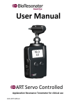
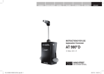
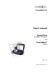
User Manual Manual Applanation Resonance Tonometer for clinical use 1011-‐ART-‐MUM-‐en IMPORTANT Read all instructions and warnings before use. ART® Manual operators must be trained before using the system. WARNING Never lift the instrument by its head, the measurement sensor can be damaged. BioResonator will only accept liability for effects on the safety, usability and design of the equipment if: - The equipment is used in accordance with its intended use, and - maintenance and repair are performed by persons authorized by BioResonator, and - installation and configuration of software are performed by persons authorized by BioResonator, and - no other software is installed in the system, and - the device is used according to the production documentation, and - the equipment is used, fitted as designed, to a slit lamp and biomicroscope, as per this manual, chapter 4, and - the equipment is checked before use as per this manual, and - the equipment may not be used if it is damaged in any way. 2 ART® Manual User Manual ART -‐ en.doc The following labels and markings on ART® Manual contain warning texts together with mandatory information and instructions: Nameplate on the exterior of the battery cover contains information relating to the mandatory requirement to read the manual before using the ART® Manual, and that on disposal of the instrument it is obligatory to follow the WEEE-‐directive. See also chapter 8.5. The Battery nameplate on the battery contains a warning not to incinerate or disassemble the battery, short the battery terminals, or expose the battery to temperatures greater than or equal to 100 °C since this involves risk of fire or explosion. The nameplate also includes information regarding the mandatory requirement to dispose of the instrument according to the WEEE directive, see also chapter 8.5. The nameplate on the inside of the battery compartment contains information about the type of battery (Varta EasyPack L) and arrows indicating in which way the battery contact plates should be oriented. ART® Manual User Manual ART -‐ en.doc 3 Contents 1 2 Introduction .................................................................................. 6 1.1 1.2 1.3 1.4 1.5 1.6 1.7 1.8 Definitions .................................................................................................... 6 General description ...................................................................................... 6 Intended use ................................................................................................ 6 Indications .................................................................................................... 7 Contraindications ......................................................................................... 7 Normal use ................................................................................................... 7 Intended users .............................................................................................. 7 The Manual .................................................................................................. 8 System description ....................................................................... 9 2.1 2.2 The ART® unit .............................................................................................. 9 Standard accessories .................................................................................. 11 2.2.1 2.2.2 2.3 3 4 5 6 T-‐ mount ........................................................................ 11 Battery and battery charger .......................................... 11 Accessories ................................................................................................. 12 2.3.1 R-‐mount ......................................................................... 12 Safety rules ................................................................................. 13 3.1 3.2 3.3 3.4 Intended use .............................................................................................. 13 General Safety rules ................................................................................... 13 Patient safety ............................................................................................. 13 Functional safety ........................................................................................ 14 Handling ...................................................................................... 15 4.1 Assembly .................................................................................................... 15 4.2 4.3 4.4 Battery charging and handling ................................................................... 18 Control panel .............................................................................................. 20 Visual information ...................................................................................... 22 4.5 Audible signals ............................................................................................ 25 4.1.1 4.1.2 4.1.3 Fitting of ART® unit on slit lamp/biomicroscope. ......... 15 T-‐mount ......................................................................... 16 R-‐mount ......................................................................... 17 4.4.1 4.4.2 4.4.3 4.4.4 Aligning light symbol ..................................................... 22 Battery symbol .............................................................. 23 Messages ....................................................................... 23 Error Messages .............................................................. 25 Measuring ................................................................................... 26 5.1 5.2 5.3 5.4 Prepare for measurement .......................................................................... 26 Measuring procedure ................................................................................. 26 Interpretation of quality index ................................................................... 28 Measurement flowchart ............................................................................ 29 Care and maintenance ................................................................ 30 4 ART® Manual User Manual ART -‐ en.doc 6.1 6.2 6.3 Overview .................................................................................................... 30 Safety check before/during use ................................................................. 30 Cleaning and disinfection ........................................................................... 31 6.3.1 6.3.2 6.4 6.5 6.6 6.7 7 8 Cleaning the casing ........................................................ 31 Cleaning of sensitive parts ............................................. 31 Battery ........................................................................................................ 33 Storage ....................................................................................................... 33 Automatic system check, calibration ......................................................... 33 Training, advice and help ........................................................................... 33 Troubleshooting ......................................................................... 34 7.1 7.2 Error Messages ........................................................................................... 34 Common causes of Measurement faileds .................................................. 34 8.1 8.2 8.3 8.4 8.5 Technical Specifications ............................................................................. 35 Aligning light intensity ................................................................................ 36 Other accessories/items (not supplied) ..................................................... 36 Guarantee .................................................................................................. 36 Support and service, collection .................................................................. 37 Appendix ..................................................................................... 35 ART® Manual User Manual ART -‐ en.doc 5 1 Introduction 1.1 Definitions ART® IOP Applanation Resonance Tonometer Intraocular pressure 1.2 General description The Applanation Resonance Tonometer ART® Manual (”ART®”, ”the ART® unit”) is a new type of contact tonometer, intended for use by ophthalmologists, trained and experienced in use of contact tonometers. A resonance sensor with an integral aligning light is applied to the centre of the patient's cornea. On contact with the cornea, the system senses the size of the area applanated by the sensor. By continuously measuring the force and the contact surface, the intraocular pressure (IOP) can be calculated. The operator hears an audible signal when a sufficient contact surface has been obtained and also when sufficient data has been collected and the sensor tip can be removed from the cornea. Numerical results from calculation of IOP and a quality index, Q1, Q2 or Q3, are shown on the unit's display. The quality index reflects the quality of the measurement series, with Q1 being the highest quality and Q2 being good quality. It is recommended that Q3 level readings be repeated. The user is provided with information via both a visual display and audible signals. 1.3 Intended use The ART® unit is designed to measure intraocular pressure (IOP) during eye examinations by direct measurement of intraocular pressure on an anaesthetised cornea. 6 ART® Manual User Manual ART -‐ en.doc The unit is intended for use by personnel trained specifically in use of this unit. For training and information about the ART® Manual – contact your local dealer, see section 6.7 and 8.5. 1.4 Indications Indications for use include the diagnosis and follow-‐up of patients with suspected abnormal intraocular pressure. 1.5 Contraindications Use of the unit is contraindicated where contact with the cornea may cause or aggravate injuries and/or pathological conditions or cause unnecessary suffering for the patient. Contact lenses must be removed before the anaesthetic is applied. Medical diagnoses should not be made solely on the basis of measured intraocular pressure. 1.6 Normal use ART® Manual is intended for routine clinical use and it is used as an aid in diagnosing and monitoring intraocular pressure. The unit is intended to be used by personnel specifically trained in its operation. 1.7 Intended users The unit is intended for use by medically trained personnel experienced in eye examinations involving use of contact tonometers. All users must be trained to operate the unit. For training and information about the ART® Manual – contact your local dealer, see section 6.7 and 8.5. ART® Manual User Manual ART -‐ en.doc 7 1.8 The Manual Before using the ART® unit, the operator must study the information contained in this manual in order to ensure that the function and properties of this unit are taken into consideration when using it. Failure to comply with the instructions contained in this manual may entail some risk for the patient and/or the user! The following symbols are displayed on the marking on the unit and their meanings are explained below: Symbol Meaning “Type BF applied part” (IEC 60601-‐1) Read and follow the instructions for use. Failure to observe the instructions may involve some risk to the patient and/or the user. CE-‐marking (Conformité Européenne) The unit serial number SN Electrical and electronic products that must be disposed off separately in accordance with the WEEE-‐Directive A flowchart is also supplied as reference when using the ART® unit. This chart is not intended to replace the manual, and all the rules and instructions contained in the manual must be followed when using the unit. 8 ART® Manual User Manual ART -‐ en.doc 2 System description 2.1 The ART® unit The ART® system is supplied in a case containing: ART tonometer. T bracket for slit lamp (an R bracket is available as an accessory). Battery. Battery charger. Torx-‐wrench, T25. Sensor housing Sensor tip Sensor arm Instrument housing Figure 2-‐1 ART® Manual User Manual ART -‐ en.doc 9 Display Control panel Battery cover Figure 2-‐2 The battery provides power to the unit during operation. It is charged outside the unit in a separate charger. 10 ART® Manual User Manual ART -‐ en.doc 2.2 Standard accessories Standard accessories are understood to mean the accessories included in the standard version of the ART® unit. 2.2.1 T-‐ mount The unit is supplied with a T-‐mount (item # 1030-‐ART-‐T), which is used to fit the ART® unit standing on the slit lamp. Figure 2-‐3 T-‐mount See section 4.1.2 for instructions on setting up the ART® unit using the T-‐mount. 2.2.2 Battery and battery charger The unit is supplied with a battery (Varta EasyPack L, item # 1051-‐ART-‐B) and a charger (item # 1050-‐ART-‐BC) with a mains lead. The charger can operate on mains supplies of 100–240 V AC, 50–60 Hz. Figur 2-‐4 Battery and battery charger See section 4.2 for description of battery charging and handling. ART® Manual User Manual ART -‐ en.doc 11 2.3 Accessories Accessories refers to attachments compatible with the ART® unit. For information, contact the manufacturer, see section 8.5. 2.3.1 R-‐mount The R-‐mount (item # 1040-‐ART-‐R) is an accessory that allows the ART® to be hung from the slit lamp. The slit lamp/biomicroscope must have a pole for an R-‐bracket (supplied by the respective lamp manufacturer) fitted to it before the R-‐mount can be used. Figure 2-‐5 R-‐mount See section 4.1.2 for instructions on fitting the ART® unit using the R-‐ mount. 12 ART® Manual User Manual ART -‐ en.doc 3 Safety rules 3.1 Intended use The ART® unit is designed to measure intraocular pressure (IOP) during eye examinations by direct measurement of intraocular pressure on an anaesthetised cornea. The unit is intended to be used by personnel specifically trained in its operation. For training and information about the ART® Manual – contact your local dealer, see section 6.7 and 8.5. 3.2 General Safety rules The unit is not supplied with the battery installed. The battery should never be installed in the unit during transport, but should instead be stowed in its intended compartment in the case. Never keep the unit close to heat sources or places where the unit may heat up unsupervised or unknowingly (e.g. in direct sunlight) – there is a risk of burn injuries where patients and/or users touch hot components. In order to minimize the risk of external interference on the ART® unit, it must not be used close to strong sources of electromagnetic radiation (e.g. diathermy equipment). 3.3 Patient safety Use of the ART® unit must always be based on caution and professional medical assessment, especially where the patient suffers from an eye disease or condition where contact with the cornea may cause injury or aggravate an existing condition. The ART® unit must never be used unless the patient's cornea has been anaesthetised. ART® Manual User Manual ART -‐ en.doc 13 Before each measurement on a new patient, the ART® unit must be cleaned and disinfected as per the description in section 6.3. An assessment of the patient's tolerance to light intensity must always take place, after which the intensity of the aligning light should be adjusted. Section 4.4.1 contains a description of the intensity of the ART® unit aligning light. 3.4 Functional safety Never dip or immerse any part of the ART® unit in any form of liquid. If a liquid penetrates any part of the unit, it must not be used but instead must be returned to the distributor for testing (see section 8.5). Always follow the instructions for cleaning and disinfection in section 6.3. Failure to do so may result in the unit being damaged and/or exposure of patients and users to contaminated parts. Caution should be observed when touching components of the unit, especially the moveable arm and sensor housing, since incorrect handling may damage the unit, resulting in potential risk to the user or patients. No tools are required or should be used when operating the ART®. Any attempt to open or modify the unit involves a potential risk to the user and/or the patient. Handle the battery and the charger with care and ensure that the battery is charged at regular intervals. Only accessories supplied with the unit or by an official distributor may be used. Using accessories from any other source may involve a safety risk. 14 ART® Manual User Manual ART -‐ en.doc 4 Handling 4.1 Assembly 4.1.1 Fitting of ART® unit on slit lamp/biomicroscope. The ART® unit can be fitted on a slit-‐lamp/biomicroscope in two different ways: by using an R-‐mount (see section 4.1.3) and by using a T-‐ mount (see section 4.1.2.). The ART® unit has currently been tested for use with Haag-‐Streit 900 and CSO 990 slit lamps, although it can be used with most other brands. When fitted with any of the adapters, the unit's display is visible to the operator and the control panel is accessible. ART® Manual User Manual ART -‐ en.doc 15 4.1.2 T-‐mount To be compatible with the ART® unit with T-‐mount, the slit-‐lamp requires: 8.0 mm diameter centre hole, fixing track on the front edge of the fastening 9.6 mm and outer diameter on the fixing plate of >42 mm. Fitting of ART® unit on slit lamp with T-‐mount 1 Locate the ART® unit on the adapter and adjust it so that the hole in the adapter marries up with the hole in the bottom of the unit. 2 Fix the adapter to the unit with the two screws provided, see Figure 4-‐1. Use a T25 Torx-‐wrench. 3 Fit the ART® unit on the slit lamp by placing the pin on the T-‐mount in the hole in the plate on the slit lamp. Check that the unit is level and stable. Figure 4-‐1 16 ART® Manual User Manual ART -‐ en.doc 4.1.3 R-‐mount To be compatible with an ART® unit with an R-‐mount, the R‑bracket attachment shaft must have a diameter of 12.0 mm. Fitting the ART® unit on slit lamp/biomicroscope with R-‐mount 1 Remove the two cover plugs which sit over the screws (see 4-‐2). 2 Fix the R-‐mount on the ART® unit with the two included screws (see 4-‐2) after removing the two cover plugs which sit over the screws. Use a T25 Torx-‐wrench. 3 Attach the R-‐mount on the fitting axle for R-‐fixing. 4 Check the unit's stability by swinging it in both directions and then returning it to its central position (i.e. with the sensor housing facing forwards). Figure 4-‐2 ART® Manual User Manual ART -‐ en.doc 17 4.2 Battery charging and handling The battery is charged in a separate charger supplied with the unit. The battery must be charged before initial use. Instructions for use of the supplied battery charger can be found in the separate manual supplied with the unit. Always follow these instructions in order to avoid damaging the battery or the charger. A full charge is indicated by a constant green light on the charger. Remove the battery from the unit by opening the battery cover on the left side of the unit (as seen from the front) and pulling the projecting part of the cover straight out. Never open the battery cover with the compartment facing down since the battery may fall out and break. If the battery is stuck for some reason, carefully tilt the unit onto its side with the battery compartment facing downwards. Be careful and be prepared for the battery to suddenly come loose – make sure that it does not fall and knock into anything. A damaged battery may cause damage to the unit and/or personal injury to the patient and/or operator. The battery cover in the ART® unit must be kept closed during charging to prevent any moisture or dust getting in. These instructions are reversed to replace the battery: insert the battery in the unit with the contacts on the side of the battery facing inwards, see 4-‐3. Shut the cover. An audible click indicates that the cover is properly shut and is locked. Check that the battery has been inserted properly by switching the unit on and off. 18 ART® Manual User Manual ART -‐ en.doc Figure 4-‐3 The unit is not supplied with the battery installed. The battery should never be installed in the unit during transport, but should instead be stowed in its intended compartment in the case. For optimum battery life and performance, the battery should be charged at least once every six months. The first charge should take place no later than one year after delivery. ART® Manual User Manual ART -‐ en.doc 19 4.3 Control panel The ART® unit is controlled by means of two buttons located on a control panel that faces the operator. Display = On/off = Aligning light intensity Figure 4-‐4 These buttons have different functions, depending on which mode the system is in: Mode Description of buttons and display functions in different modes Off No information is displayed on the screen. The unit is switched on by pressing briefly on the ”On/Off ”-‐ button Start-‐up 20 . The unit is initiated and undergoes a system test. The buttons are inactive in this mode. ART® Manual User Manual ART -‐ en.doc Measuring mode In this mode the system waits for the sensors to detect a commenced measurement. A short press on the ”On/Off ”-‐button discontinues the measurements and moves to the display position. The light. Display mode button changes the intensity of the aligning In this mode, the measurement value from the current measurement series is displayed. A short press on the “On/Off” button leaves this mode and switches to “Measuring mode”. The unit can also go into two energy-‐saving modes: Standby-‐display In display mode the background light on the display goes off after 2 minutes of inactivity. A short press of the ”On/Off” button switches on the background light. After a further 3 minutes the unit switches off. Standby-‐measurement In measuring mode, before a measurement commences, the system returns to display mode after 2 minutes of inactivity. If a measurement has commenced, this current measurement finishes and the unit goes into display mode. In all modes, a 2-‐second press on the “On/Off” buttons switches the unit off. The message “Powering down…” shows on the display. ART® Manual User Manual ART -‐ en.doc 21 4.4 Visual information The visual information is notified via the display, which is divided up as per Figure 4-‐5. Battery symbol Aligning light symbol Pressure (IOP) 13.2mmHg Q3 n=5 .0 Measuring Message Quality index Measurement number Figure 4-‐5 4.4.1 Aligning light symbol The aligning light is only active in “measuring mode” and the chosen light-‐intensity level is shown in the display when the user adjusts the intensity. When the unit is started, the light intensity is set at level 1. Four modes of light intensity are available: 0 (off), 1, 2 and 3: The aligning light is off (level 0). The aligning light is set at level 1. The aligning light is set at level 2. The aligning light is set at level 3. Figure 4-‐6 Indication of aligning-‐light intensity. 22 ART® Manual User Manual ART -‐ en.doc 4.4.2 Battery symbol Battery status is indicated by the battery symbol on the display. When the battery is fully charged, the battery symbol is shown in full, decreasing as the battery charge reduces. When the battery requires charging, a “Charge battery” message shows on the display. The battery is fully charged. The battery is half full. The battery is empty. 4.4.3 Messages The following illustrations show examples of various values and messages that are shown on the unit's display: Figure 4-‐7 Off – no information is displayed. ART1-Software Version 1.0 2010-06-30 © BioResonator 2010 System Starting… Figure 4-‐8 Start-‐up – system information is displayed. ART® Manual User Manual ART -‐ en.doc 23 0.0mmHg Ready to measure Figure 4-‐9 Measuring mode – before first measurement. 13.2mmHg .0 Ready to measure Figure 4-‐10 Measuring mode – after accepted measurement, measurements 1 and 2. 13.2mmHg Q2 n=3 .0 Ready to measure Figure 4-‐11 Measuring mode – after accepted measurements 3, 4, 5 and 6 a quality index is also given. 24 ART® Manual User Manual ART -‐ en.doc 13.2mmHg Q1 .0 Measure complete, n=4 Figure 4-‐12 Display mode – Following completion of a measurement series, the unit switches to display mode and the measured value and quality index are displayed. 4.4.4 Error Messages Any error messages are presented on the display. See section 7.1 for a list of error messages and their content. 4.5 Audible signals The system produces audible signals that notify the operator of the unit’s status. These signals vary, depending on what mode the system is in. Signal Short, high-‐pitched tone Medium length, high-‐ pitched tone Long, multi-‐tone Long, dull tone Mode – Meaning Start–up – system started. Measuring mode – measurement commenced, stop applanation. Measuring mode – New measuring series commenced. Measuring mode – result accepted, relieve cornea. Measuring mode – measuring series finished. Measuring mode – the measuring result is not accepted, try again. Other modes – an error has occurred. ART® Manual User Manual ART -‐ en.doc 25 5 Measuring 5.1 Prepare for measurement Install a charged battery (section 4.2) in the unit and attach the unit to the slit lamp (section 4.1.3 or 4.1.2). The unit must be checked as described in section 6.1 and 6.2 (must be done before the first patient, between patients and if there is a suspected fault with the unit). The unit must be cleaned/disinfected as per instructions in section 6.3. Moisten a clean, dry cloth with spirit (70% ethanol/isopropanol). Make sure the cloth is sufficiently moist to clean properly, but not dripping wet. Carefully clean the entire sensor tip. 5.2 Measuring procedure When the ART® unit is fitted on the slit lamp and the preparations as per section 5.1 completed, the unit is ready to use. 1. Anaesthetise the patient's cornea(s) and wait for the anaesthetic to achieve its full effect. 2. Switch the unit on using the “Off/On” button 3. Wait until the display shows "Ready to measure". 4. Position the sensor tip close to the patient's eye (a distance of about 5–10 mm is suitable), with the tip centred relative to the cornea. 5. Adjust the aligning light intensity as required using the “Aligning light intensity” button 6. 26 . . Carefully move the tip forwards in a gentle movement towards the patient's eye, stopping when you hear a tone. A short, high-‐ ART® Manual User Manual ART -‐ en.doc pitched tone confirms that a measurement has been started; a long dull tone indicates an error in measurement and measurement is then repeated. 7. Once the system has sufficient data to calculate the IOP, the unit emits a high-‐pitched/light tone once again and the sensor tip must then be withdrawn from the cornea. If the measurement was conducted correctly and the measurements have been accepted, the calculated values are shown on the display and the message “Ready to measure” is shown once again. If a measurement fails, a dull tone is emitted and the system ignores the data collected. An error message displays for 3 seconds, and the system then returns to measuring mode. The message “Ready to measure” is then redisplayed. 8. Repeat steps 6–7 up to five more times to obtain a complete measurement series. The user may stop the measurement at any time by pressing the “On/Off” button . When the measurement series is concluded, the messages “Measure complete” displays, and the system returns to “display mode” for the current measured value. A measured value usually consists of a consecutive series of three individual, two second duration measurements. If Q1 is obtained, the measurement series is stopped and an IOP value is shown on the display. If Q2 or Q3 is obtained, the operator can choose to extend the measurement series to a maximum of six repetitions. The operator can choose to stop the measurement at any time (though a Q index is not obtained until after three individual contacts with the cornea). If an insufficient number of measurement points have been collected during one measurement (e.g. due to the patient blinking during the ART® Manual User Manual ART -‐ en.doc 27 measurement) the system can still calculate the IOP based on the available data (so-‐called “dynamic analysis”). 5.3 Interpretation of quality index Once three measured values have been obtained (n=3) a quality index is displayed together with an IOP value. Q1: Measuring series with high reliability. Q2: Measuring series is OK, but the measuring series’ standard deviation is somewhat high. Q3: Measuring series has high standard deviation and should be repeated. All measured values are shown in millimetres of mercury [mmHg]. 28 ART® Manual User Manual ART -‐ en.doc 5.4 Measurement flowchart Measuring procedure Display: -‐ Off On/Off (short press) Start-‐up Display: System information Tone: Intermediate Measuring mode Display: Latest measured value Display: ”Ready to measure” Tone: Long, high Application against cornea Tone: Long, low Correct measurement Tone: Short, high Measurement failed Stop applanation Await audio signal Symbols Button press/select System response Measuring event Figure 5-‐1 ART® Manual User Manual ART -‐ en.doc 29 6 Care and maintenance 6.1 Overview The user must visually/manually inspect the unit and its accessories prior to use. The following points must be checked: • Status of the battery cover – the cover must not be loose • Sensor housing and sensor arm – must be undamaged and not subject to any strain • Instrument housing – no scratches or damage to the control panel • • No visible fluids/moisture on any part of the unit or accessories R-‐/T-‐mount – correctly attached to the unit • R-‐/T-‐mount and unit – firmly mounted on the slit lamp 6.2 Safety check before/during use The following points must be checked before use; while using the ART® unit to take a measurement series, and also if there are any doubts concerning the function or safety of the instrument. See Figure 6-‐1 below for guidelines. Tip: these checks may be performed at the same time as the unit is cleaned/disinfected as per section 6.3. 1. 2. Check that the unit is properly attached to the adapter in use (R-‐ or T-‐mount). The unit must be firmly attached to the adapter and the adapter must be firmly and securely mounted on the slit lamp. Check that the sensor tip is undamaged and properly located. 30 ART® Manual User Manual ART -‐ en.doc Sensor tip Sensor housing Figure 6-‐1 6.3 Cleaning and disinfection None of the ART® unit's components/parts or accessories may be exposed to sterilisation processes. The unit and its accessories are not cleaned/disinfected when supplied, but this must take place before initial use. 6.3.1 Cleaning the casing The instrument housing, the sensor housing, the sensor arm and any accessories must be cleaned at regular intervals; the recommended interval is once daily, more frequently in the presence of suspected contamination. All components must be cleaned before storing in their storage case. The recommended method of cleaning these parts is drying with an alcohol swab or soft cloth/towel (e.g. Kleenex-‐towel) lightly moistened in alcohol (70–96% Ethanol/Isopropanol). Note that the cloth must not be dripping wet as this may damage the unit. 6.3.2 Cleaning of sensitive parts The sensor tip, the sensor element and the connector at the end of the sensor housing must be cleaned as described below before the first ART® Manual User Manual ART -‐ en.doc 31 measurement, between patients, after a completed measuring period (i.e. at the end of the day) and also before the unit is packed away in its storage case. 1. Moisten a clean, dry cloth with spirit (70% ethanol/ isopropanol). Make sure the cloth is sufficiently moist to clean properly, but not dripping wet. 2. Carefully clean the entire sensor tip, the part of the sensor element that is accessible and all round the entire connector. See Figure 6-‐2. Avoid direct contact with the fingers. Check that the sensor tip is undamaged. 3. Note that the sensor element contains a small proportion of nickel. 4. Allow all cleaning agents/fluids to evaporate before using the unit. Sensor tip Flange Sensor housing Sensor element Figure 6-‐2 Never use cleaning agents that are applied by means of a spray can or similar as this may damage the unit. Never use any kind of tool or brush for cleaning as this may damage the unit. 32 ART® Manual User Manual ART -‐ en.doc If you are at all uncertain about cleaning, its effect or the unit's function and/or safety, stop using the unit and contact the distributor for advice (see section 8.5). 6.4 Battery To obtain optimum battery life and performance, the battery should be charged at least once every six months. 6.5 Storage The climate in which the unit is stored must meet the criteria stated in the technical specifications in section 8.1. 6.6 Automatic system check, calibration When the unit is switched on (from the off mode) the system runs a self check. This includes checking the resonance sensor, the power indicator and other system parameters. If the system should detect an error or deviated value, the user is presented with an error message. If this happens, stop using the unit and report the fault to the distributor (see section 8.5). The unit is calibrated on supply from the distributor, and no new calibration is required with normal use. If you suspect deviating results and/or incorrect function as a consequence of incorrect calibration, stop using the unit and report the fault to the distributor (see section 8.5). 6.7 Training, advice and help All operators must undergo training for the ART® Manual unit approved by BioResonator AB. For training, advice and help with the ART® Manual unit and its accessories, contact your local distributor. For contact information, see section 8.5. ART® Manual User Manual ART -‐ en.doc 33 7 Troubleshooting 7.1 Error Messages The following error messages may be displayed when taking measurements using the ART® unit: Error message Measurement failed Meaning/cause See 7.2 for usual causes Charge battery Technical problem, contact distributor The battery needs charging Fault in resonance sensor – contact distributor, see 8.5. 7.2 Common causes of Measurement faileds There are a number of reasons why the unit may give erroneous measurement results, or indicate errors in measurement. Frequent causes are found below: • Object between the sensor tip and the cornea surface (e.g. hair strand, part of the eyelid etc.) • The patient blinked during the measurement procedure • The patient moved during the measurement procedure and the sensor tip lost contact with the eye • 34 The patient has abnormally moist or dry corneas ART® Manual User Manual ART -‐ en.doc 8 Appendix 8.1 Technical Specifications These technical specifications are valid for a period of 6 years from the date of purchase, providing that all instructions in this manual have been complied with. Item number Description Type of instrument 1460-‐2AD034 Applanation Resonance Tonometer Contact tonometer Name Classification ART® Class IIa (according to MDD 93/42) Certification (EU) Ultrasound intensity (estimated) 2 134 mW/cm IOP measuring range IOP accuracy of measurement 7–50 mmHg ± 0.2 mmHg (Numerical precision) Battery voltage Battery model 3.7 V VARTA EasyPack L Battery charger Usage time: (for 5 measurements/hr) Dimensions Temperature range (in use) RRC EZP06DC At least 8 hours Temperature range (stored) Air pressure (in use) -‐10–55 °C 800–1060 hPa Air pressure (stored) Ambient humidity (in use) Ambient humidity (stored) 700–1060 hPa 30–75 % 10–95 % Weight (without/with battery, approx.) 193/221 g ART® Manual User Manual ART -‐ en.doc 172 (H) x 83 (W) x 71 (D) mm 10–35 °C 35 Weight (including packaging) (with accessories, approx.) ~3000g 8.2 Aligning light intensity The ART® unit has an aligning light which facilitates centring of the sensor on the cornea to ensure correct contact when taking a measurement. The light source is a light-‐emitting diode (LED) that produces white (visible) light. The total width of the beam emitted by the LED is 380 – 800 nm. The maximum available energy for powering the LED (at maximum intensity) is 80 mW, and at an optimised efficiency of 25% (the normal efficiency for this type of LED is 10–20%) the emitted optical output is approx. 20 mW (not taking into account loss due to the light's passage through the sensor tip). The norm for ophthalmological instruments (EN ISO 15004) limits the permitted radiated light intensity in the wavelength range 380–700 nm to 49 mW. Consequently, 20 mW < 49 mW is deemed to be the maximum acceptable radiated light intensity of the ART® instrument with regard to possible risks for patient and user. 8.3 Other accessories/items (not supplied) • R-‐mount for mounting the ART onto a biomicroscope. • Cleaning/disinfection agent – see section 6.3 for information about recommended agents. 8.4 Guarantee For guarantee terms, see the separate guarantee slip (delivered with the unit or provided by the local distributor). 36 ART® Manual User Manual ART -‐ en.doc 8.5 Support and service, collection All maintenance and servicing of the ART® unit and its accessories is to be performed by the local distributor or someone acting on their behalf. The ART® unit has no parts that can or must be repaired by the operator/user. Any attempt to repair and/or modify the unit represents a breach of the guarantee terms and as a result the function and safety of the unit cannot be guaranteed. For local distributor, visit: www.bioresonator.com Manufactured by: Address: BioResonator Good Eye AB Tvistevägen 47, Box 7952 SE -‐ 907 19 Umeå Sweden URL: http://www.bioresonator.com E-‐mail address: [email protected] Note that the unit contains substances that may be harmful to people, animals and the environment. The unit may not be disposed of by the user, but it must instead be returned to the distributor. Used batteries that can no longer be fully charged must be disposed of in accordance with local laws and regulations. ART® Manual User Manual ART -‐ en.doc 37 2014-‐10-‐10