1
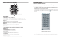
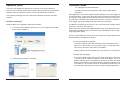
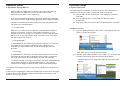
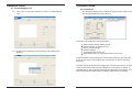
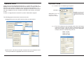
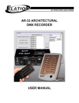
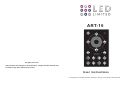
ART-16
C
S
B
1-8
SAT
9-16
A/M
All rights reserved.
PAGE
1
2
3
4
5
6
7
8
Improvement and changes to specifications, design and this manual may
be made at any time without prior notice.
User Instructions
It is important to read this instruction book prior using your new product for the first time.
Table of Contents
Introduction........................................................................................................1
Key Features......................................................................................................1
Specification.......................................................................................................1
Control Panel and Functions..............................................................................2
Cabling Requirements........................................................................................3
Operation Guide...........................................................................................4~29
1. Software Installation................................................................................4
2. System Connection.................................................................................5
3. Software Launch.................................................................................5~6
4. Software Application..........................................................................7~27
4.1. Create Mapping File..................................................................8~12
4.2. Create a Pixel Mapping...........................................................13~15
4.3. Update Mapping File.....................................................................16
4.4. Review...........................................................................................17
4.5. Low Cut.........................................................................................18
4.6. File Covert...............................................................................18~19
4.7. Show Edit................................................................................20~24
4.8. Event Edit................................................................................25~27
5. Operation Tips on ART-16...............................................................28~29
6. DMX Channel Selection, DMX Value & Functions Table.......................30
7. Program Updating.................................................................................30
8. Remote Controller Operation..........................................................31~32
Operation Guide
Keys
Introduction
Functions
OFF
Powers on or off the unit.
Auto
Selects auto mode.
Manual
Selects manual mode.
Bright
Selects bright.
Speed
Selects speed.
Saturation
Selects saturation.
Color
Selects color.
Page
Pages down/up to select show 1~8 or show 9~16.
Show1~Show8
Used to select show 1~16.
Holding the key down will gradually increase to the maximum
value of Bright, Speed, Saturation or Color.
Holding the key down will gradually decrease to the minimum
value of Bright, Speed, Saturation or Color.
NOTE:
Effective distance from ART-16 to LED Remote controller shall be limited
within the range of 10m. Otherwise, it results out of control.
Congratulations and thank you for purchasing our ART-16.
The ART-16, a hybrid LED controller with the touch interface. It consists of
EU(ART-16E) and US(ART-16U) version for user selection. Compact, pocket
and professional design for easy operation.
Key Features
---- Touch interface
---- Maximum 170 RGB lightings can be controlled via USITT DMX512(1990
protocol) or maximum 680 RGB lightings can be controlled via
DMX-1000K(1M) protocol
---- Allows connecting with PC via USB port
---- Programmed flash files can be transmitted to fixture via Standard RJ45
---- Flash(.swf ) playback and conversion
---- Capability of DMX recording, supports BBP recording
---- Allows built-in real time clock to set trigger time for each show
---- Up to 200 files of maximum 128M can be recorded in memory to
control DMX signal files
---- Built-in 16 shows, allows the professional ART-16 configuration
software to designate the 16 shows separately
---- Program long-distance updating
---- Adjustable DMX playback speed
---- Available in DMX Control Mode, Time Trigger Mode and Manual
Mode
---- Infrared remote control
---- Function memory and Power failure protection
Specification
Power Requirement........................................Junction Box 1 (Sold Separately)
Power Output....................................................................................DC 12~24V
Housing........................................................................................Ploycarbonate
Dimensions.................................................170 x 85 x 15.5 (mm) for EU version
.............76 x 120 x 15.5 (mm) for US version
Weight..................................................................................200g for EU version
.......................................150g for US version
32
1
Control Panel and Functions
Operation Guide
8. Remote Controller operation
12
4
A built-in IR EYE sensor enables you operator your ART-16 by remote controller.
1
C
7
3
6
11
S
B
1-8
SAT
9-16
A/M
PAGE
1
2
3
4
5
6
7
8
5
8
9
10
ART-16U
8.1.Operation Instructions
8.1.1. Before operation, make sure the batteries(3V, CR2025) have been
installed into the remote controller properly.
8.1.2. There are 8 dedicated Show keys, Auto, Manual, OFF, Bright, speed,
Color, Saturation, Page, Raise & Lower keys( / ) on the remote controller
interface.
Auto
Man u al
OFF
2
1.Power Button
Used to power on/off your ART-16.
2.Button 1~8
When indicator 1~8 was selected, Button 1~8 mean the show 1~8.
When indicator 9~16 was selected, Button 1~8 mean the show 9~16.
3.Button C
Color, to choose it, the color can be adjusted.
4.Button B
Brightness, to choose it, the brightness can be adjusted.
5.Button S
Speed, to choose it, the speed can be adjusted.
6.Button SAT
Saturation, to choose it, the color saturation can be adjusted.
7.Touch Toggle
Used to adjust the Color, Brightness, Saturation and Speed.
8.Indicator 1~8
It will be lit when show 1~8 selected.
9.Indicator 9~16
It will be lit when show 9~16 selected.
10.Page Button
Alternates between show 1~8 and show 9~16.
11.A/M Button
Alternate between Auto Mode and Manual Mode.
12.Built-in IR Sensor
Receives the signal of external infrared remote controller.
2
Bright
Show 1
Show 2
Speed
Show 3
Show 4
Saturation
Show 5
Show 6
Color
Show 7
Show 8
Page
ART-16
Remote Controller
ART-16 Remote Controller
8.1.3. The detailed function will be illustrated in the following table.
31
Operation Guide
Cabling Requirements
6. DMX Channel Selection, DMX Value & Functions Table
DMX Channel Selection
DMX Values & Functions
Starting Channel
0 ~3, trigger Show1;
4~7, trigger Show2;
9~11, trigger Show3;
........
60~63, trigger Show16
Above 63, shut Show
Starting Channel
+1
0~79 , Pause;
80~159, Play;
Above 159 ,Stop.
Starting Channel
+2
0~127 , Normal Output,
129~255, Blackout.
It is required to use a standard USB link cable to connect ART-16 with PC ,
meanwhile, a power distributor(Junction Box 1----Sold Separately) provides
power to the ART-16 system and the ART-16 link with it for receiving power
source and transmitting data via Category 5 Ethernet LAN cable.
Note: Please refer to the "Show Edit" of the ART-16 Configuration
Software for the DMX address setting.
7. Program updating
The user may follow the below steps to update program for ART-16.
Junction Box 1
Note: To learn the more information about Junction Box 1, please read it’s
user manual.
7. 1.Open the rear panel of the ART-16.
7. 2.Flip the dual-way Dipswitch "2" to "on".
7. 3.Connect the power source for your ART-16 and connect it to
PC via USB cable.
7. 4.Reboot the "ART-16 Configuration Software" and download
"Art-16Prog.scn" file to your ART-16 in function of "Show Edit".
7. 5.After download successfully, flip the dual-way Dipswitch "2" to "off".
Assemble the rear panel.
7. 6.Updating complete.
30
3
Operation Guide
Operation Guide
The ART-16 is capable of holding up to 16 shows in memory, limited by a
memory size of 128 Mb. Shows are configured using the ART-16 Configuration
Software. Also the software is used to covert and load shows to ART-16.
The software is designed for use on Microsoft Windows computer operation
systems.
1. Software Installation
Install the ART-16 Configuration Software as follows:
1.1. Locate the ART-16SetupVerX.XX.exe on your computer and double
click to begin installation.
5.4. Speed(S) and Saturation(SAT)
Likewise, the users may adjust the value of the Speed and the
Saturation
While adjusts the value of the Speed and the Saturation, the touch toggle can
be used circularly. In clock wise, when the value reaches the maximum,continue
to rotate the touch toggle, the value will start from the minimum to increase. In
anti-clockwise, when the value reaches the minimum, continue to rotate the
touch toggle, the value will start from the maximum to decrease.
The Button S and SAT will be void once any scene file which exceeds 512K was
posted to 1~16 show of the ART-16.
After the function S was activated(the backlight is lit), press and hold on the S
button till the backlight is fade out the driver may automatically return to the
original palyback speed.
There is a same default scene file in each of 16 shows and this default scene
file will always be available and existing.
5.5.Auto and Manual mode(A/M)
To touch the Button A/M, while the Button clicks and lights red, the
ART-16 is in auto mode. Prior to use this mode, it is required to edit
events first, otherwise, this mode is unavailable.
While the Button clicks and lights white, the ART-16 is in manual mode.
5.6.Page down/up(Page)
1.2. Following the prompts to complete.
To touch the Button Page, the user may page down/up to select show
1~8 or show 9~16. While the indicator 1~8 is lit, the Button 1~8 on the
panel means the show 1~8 separately, the user may select the desired
show by touching the corresponding Button. While the indicator 9~16 is
lit, the Button 1~8 means the show 9~16 separately, likewise the user
may select the desired show by touching the corresponding Button.
....
4
29
Operation Guide
Operation Guide
5. Operation Tips on ART-16
2. System Connection
After the ART-16 Configuration complete, pull out the USB cable for
disconnection from ART-16 to your PC, the ART-16 will reset
automatically and then you are ready to go.
In the control interface of the ART-16, the touch toggle may control the
value of the Color(C), Brightness(B), Speed(S) and the Saturation(SAT).
The ART-16 features touch button design, the users may easily select
the function by touching buttons.
5.1. Power on/off
Make sure your ART-16 connect with the power distributor suitably in
advance of operation. Touch the power Button and hold it on for 2
seconds to power on the ART-16 , the Button of Power, Page and A/M
will be lit. Touch the Power Button again and hold it on for 5 seconds,
the ART-16 goes into stand by .
Complete software installation, to set up the active ART-16 System for
operation, connect the system components together as follows:
2.1. Connect ART-16 and Junction Box 1 with Category 5 Ethernet
LAN cable.
2.2. Connect ART-16 and PC using USB link cable for system
configuration.
2.3. Plug power cable into Junction Box 1 a 230VAC-50Hz receptacle.
3. Software Launch
3.1. From the Windows desktop, select Start > All programs> ART-16
>ART-16, as the follow figure.
5.2. Brightness(B)
To select Button B, the Button will click and the indicator is lit. The user
may rotate the touch toggle to adjust the value of Brightness. In
clockwise, the value will increase. In anti-clockwise, the value will
decrease.
5.3. Color(C)
To select Button C, the Button will click and the indicator is lit. The user
may rotate the touch toggle to adjust the value of Color. In clockwise,
the value will increase. In anti-clockwise, the value will decrease.
In case the user did not configure any Shows, the show will automatically
run the built-in program of controlling RGB lightings. The user may
rotate the touch toggle to adjust the color value for the RGB lightings.
Click "ART-16", you can get software launch.
3.2. Normally, for the easily locate the icon of ART -16, the user is allowed
to create a shortcut for ART-16 on the Windows desktop.
Follow the figure of 3.1., Right click "ART-16", the follow figure
appears.
The value of the Brightness and the Color can be adjusted in the range from 0
to 255.
In the process of adjusting the value of the Brightness and the Color, the toggle
produces the key tone. While the value reaches either the maximum or the
minimum, the key tone is mute.
28
5
Operation Guide
Click "Desktop(create shortcut)", the shortcut will be created on
windows desktop.
Operation Guide
4.9.2. Calendar Events
Assign Calendar Events to a show as follows:
4.9.2.1 Select a Date Start and Date Stop from the Date Select area.
Double click the icon of "ART-16" on windows desktop to launch
software.
4.9.2.2. Set Event Start and Stop Time in the time Select area.
4.9.2.3. Select "Save". Saved events will display in the window on the
right side of the screen.
4.9.2.4. If a saved event is incorrect, it may be moved by highlighting the
event and select "Delete".
4.9.2.5. Select "Download To ART-16" to download events to the ART-16.
6
27
Operation Guide
4.9.1. Weekly Events
Assign Weekly Events to a selected show as follows:
4.9.1.1 Select the days(or everyday) for the show to play from the
Weekly Events area.
Operation Guide
4. Software Application
When ART-16 Configuration Software is launched, the following
main screen is displayed.
4.9.1.2 Set Event Start and Stop Time in the Time Select area.
4.9.1.3 Select "Save". Saved events will display the window on the
right side of the screen.
From the main screen, users may perform the following actions.
4.9.1.4 If saved event is incorrect, it may be removed by highlighting
the event and selecting the "Delete".
4.9.1.5 Select " Download To ART-16" to download events to the
ART-16.
Access File, Edit, and Help menus.
"Open Flash" files and assign each of the 12 "FlashX" buttons.
"Play, Pause, Stop " selected flash.
"Preview" to a programed screen
"Update Mapping " after your mapping modification.
"File Convert " converts your .swf file to .scn file
Open "Edit Show" to edit shows
Open "Event Edit" to edit events as the users desired
Select Low cut (on/off)
Record "DMX Recorder" scene to a .scn file
Select Fixture
Set RGB Brightness(70~255)
4.9.1.6 The software will prompt you when the download finished.
Click "OK".
26
7
Operation Guide
4.1. Create Mapping File
4.1.1. Click "File", a drop menu appears, to select "Create Mapping
File".
Operation Guide
4.8. Event Edit
The Event Edit allows user to set timed trigger for each of the 16 show
files and download them to the ART-16.
The users may perform the following actions:
4.1.2. A dialogue box"Warning! This will change the mapping file"
appears.
Select show to assign thimed events
Select Calendar or Weekly events
"Save" current settings
"Delete" settings
"Load All Scenes To ART-16"
"Download to ART-16" (save timed events to ART-16)
The Events Edit screen displays the current date and time in the lower left
corner of the screen. These values are synchronized by the PC time and
date time.
To select a show for timed event assignment, use the drop menu in the top left
corner of the screen. Next, choose whether the event will occur based on
calendar date or day of week by selecting the appropriate radio button. The
screen will anable the Date Select or Weekly Select areas accordingly.
8
25
Operation Guide
Assign scenes to the selected show using the ">","Insert" and "<" bumps. To
highlight a scene in the ART Scenes File List and select">" to add it to the show
list on the right. Likewise, highlight a scene in the show list and select "<" to
remove it from the show. To insert a scene, highlight it in the ART-16 Scene File
List, then highlight the scene it should be preceded in the show list, and select
"Insert".
To save a configured show to the ART-16, select "Download to keypad".
Operation Guide
4.1.3. Select "Yes", the default figure appears.
Work Grid
Add Node is an option that allows
to add new node as needed,
respectively entering its name, total
output ports and total channels per
port.
Select Node is a drop menu
that allows to select a
exiting device as desired.
The following figures shows how to insert a scene file.
1)Highlight the scene in the ART-16 Scene File List and show list.
4.1.4. The user is allowed to use the default value, click "OK" Bump to
enter into next step, or the user prefer to edit the desired value of
Work Grid on Width, Height and Channels, even to add Node. For
example, make the corresponding value as
Width: 30 pixel
Height: 20 pixel
Channels: 1800
2)Click "Insert", the Scene in the ART-16 Scene File List is inserted to show
list and precedes the highlighted Scene File in the show list.
24
9
Operation Guide
Note:
Before building a pixel map, it is advisable to check how many pixels all devices
will occupy when customize your Work Grid. The Work Grid is large grey area
for a pixel map build. The Width is horizontal pixel, the Height is vertical pixel.
Enter the value of Width and Height to customize Work Grid size respectively.
Operation Guide
Select "Format Device" will erase all ART-16 scenes from device memory. The
software will prompt you with a warning to confirm this action.
The Width is an integer number from 1 to 640, the Height is an integer number
from 1 to 480.
In this option, the user is allowed to add a new device by the following steps,
1) Click the "Add Node" icon.
2) Enter Device Name, Output Port Number and Channel Number.
3) Click the "Save Node" icon to save the existing setting.
4.1.5. After the customization complete, Click "OK", a "X- Mapping" figure
appears. The user can perform the below actions.
Selects the exiting device.
"Edit/Add" device.
"Convert map address" when complete mapping re-edit.
Up to 200 DMX scene files(.scn) of maximum 128M in total can be assigned to
ART-16. And up to 16 scene files may be assigned to each of the 16 show
locations. Select the show to configure using the drop menu in the top right
corner of the screen. Set the base address of the ART-16 in the DMX address
field. This allows a DMX device to trigger the ART-16 remotely.Set fade time in
the Fade Time Field.
Note: The Fade Time determines how many seconds it takes to change from
scene to scene.
10
23
Operation Guide
To save scene files currently displayed in the ART-16 Scene File List to PC.Click
"Save All Scenes To PC" . The software will prompt you to enter a save location
folder name
Operation Guide
4.1.6. Select "Edit/Add..", the "X-Mapping Edit List" appears.
To load all scene files from PC folder to the ART-16 Software, click "Load All
Scenes To ART-16". The software will prompt you to select a save location
folder from which to load.
All default fixtures were listed in Fixture Library List, the user can perform the
actions as follow.
"Add Device" to add a new dummy device
"Modify" to modify an existing device
"Delete " to delete an existing device
4.1.7. Click "Add Device", the "X-Mapping Device Create" figure appears.
To delete a scene file from PC folder to the ART-16 Software, highlight the
desired file and click "Delete Scene File". The scene file is removed from the
list. Take care to save your files in your PC before deleting them from ART-16
Scenes File List as this action cannot be undone.
22
11
Operation Guide
Name can be modified for different groups or unique device designs as
needed.
Horizontal and Vertical Pixels define the overall number of pixels in the
existing device.
Horizontal and Vertical Skip define the offset between adjacent pixels in
the device, can be used to skip a pixel within the device when it's placed
on the Work Grid. Instead of having 5 consecutive pixels in a standard 5x5,
you can have 5 pixels skipping one pixel in between.
Scan Order is a drop down that displays device scan order, defines the
direction and order in which the pixels are connected. A specific scan order
may reflect the requirements of actual connection order.
Examples of standard scan orders...
Left->Right->Top,
Right->Left->Top,
Top->Bottom->Left,
Bottom->Top->Left,
Left->Right->Left,
Bottom->Top->Bottom,
Top->Bottom->Top,
......
Click "OK" Bump to save the setting. The created devices will be listed in
the device library list.
Operation Guide
Click "Read Current ART-16 Scenes" to load current ART-16 scenes files from
the controller into the software. Scenes display in the ART-16 Scenes File List
window. Scene display in alphabetical order, and DO NOT retain any show
mapping or sequencing.
The user may load any ART-16 scene files into PC for storage or backup. To
highlight the desired scene and click "Save Scene To PC". Likewise, any scene
file may be loaded into ART-16 from PC. To load a scene file, select "Load
Scene To ART-16".
To highlight the desired scene and click "Save Scene To PC". The following
screen appears, to type the File name and click "Open", the scene file may
be stored into the PC as .scn type. A progress bar will show the posting
progress.
4.1.8. Follow the step4.2.6 to choose the device as X-Panel and click
"OK". To set its scan order as Left->Right->Top in "X-Mapping
Device Create".
To click "Load Scene To ART-16", select the scene file which desired to load
into ART-16, the scene file may load into the ART-16.
12
21
Operation Guide
4.7. Show Edit
The Show Edit screen allow user to configure each of the 16 shows and
transfer files between the ART-16 and the PC.
The DMX scene file(.scn) can be loaded to ART-16 automatically and
seen in "ART-16 scenes File List".
The user may perform the following actions:
"Read Current ART-16 Scenes"
"Save Scene To PC"
"Load Scene To ART-16"
"Save All Scenes To PC"
"Load All Scenes To ART-16"
"Delete Scene File"
"Format Device"
Assign(Add, Insert & Delete) scene file to show memory location
Assign ART-16 DMX address
"Download To Keypad"(save individual show settings to ART-16)
"Fade Time"(preset a fade time )
20
Operation Guide
4.2. Create a Pixel Mapping
After your devices and fixtures settings completed, access to built a
pixel map as needed. It is required to follow the below steps to create
a pixel map.
4.3.1. Select an existing device(e.g. X-Panel) which you wish to create
a pixel map.
4.2.2. Click the Grid(
map.
) to array device's pixels and create the pixel
13
Operation Guide
4.2.3. While placing the pixel map completed, click Arrow(
shows as below.
Operation Guide
4.6.5. A new dialogue box appears. It shows that the flash file(.swf) you
selected will be saved as DMX scene file( .scn).
), the figure
4.6.6. Click "Save" to save the file route and file name. A progress bar
shows the conversion progress.
In the pixel map, the area marked with 1:1 which figures mean the device
address. The first figure means the outport, the second figure means the
address of the outport.
4.2.4. The user can double click the area of the fixture address to assign
the device address according to the scan order(Left->Right->Top)
which has been set up. As following figure shows,
Note:
The name of the DMX scene file(.scn) should not exceed 16 characters .
14
19
Operation Guide
Operation Guide
4.5. Low Cut
While the users select the Low Cut,the LED fixtures perform as the follow.
21
4.5.1. The brightness was set as the value which is less than 255 X 100%,
the fixtures will black out.
.
Remark:
In the event of any mistake happen, user can modify it by right click the device
address with the mouse. A dialog box will display , to enter a correct number,
then click the ''OK'' icon to save the modification. You MUST ensure overall pixels
array order is matching with their scanning order which has been set up.
22
4.5.2. The brightness was set as the value which exceeds 255
X 100%,
the fixtures will light in weak.
.
4.6. File Convert
4.6.1. Flash files may be converted to DMX scene files(.scn) and loaded
to ART-16.
4.6.2. With desired file loaded in ART-16, select "File Convert", the follow
screen apears.
4.2.5. After device address setting complete, click"Convert map
address" to covert the pixel map address. A progress bar
shows conversion progress as follow figure.
4.6.3. Enter flash file playback speed in frames per second. The range
of the Flash Frame is 1~35 Frame per second.
4.6.4. Click "OK".
18
15
Operation Guide
4.3. Update Mapping File
Operation Guide
4.4. Preview
Click "preview", both Button 4 & 8 of ART-16 flash ceaselessly, the
device is lit in full on simultaneously.
4.3.1. While Convert map address successfully, close its screen and
go back to the below screen.
Click "Open Flash", the dialogue box will guide the user to select a flash
file from computer .
While the user selected a flash file, the Preview Screen will preform it,
simultaneously the device displays the flash as well.
4.3.2. Click "Update Mapping file", a new Preview Screen appears, its
size is the same as the device performance area.
The user can click "Pause" to pause the Preview Screen, click "Stop"
to stop the Preview Screen or click "Play" to resume play.
Note:
1)The Preview Screen is able to play and preview the file directly .
2)Only flash(.swf) files can be played in Preview Screen.
3)The RGB intensity of the pixels can be adjusted separately from 70~255.
4)How many pixels in the drop down menu of Fixture which rest with the
quality the user had set up.
5)After RGB intensity adjustment completed, click "Save" to save your
setting.
16
17