1
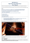
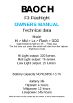
FMT DRV V2
High Power Laser Diode Driver
User’s Manual
Thank you for purchasing the FMT DRV. V2 - boost/buck constant current output laser diode/LED driver.
Specs:
Max. output current in boost mode = ~2A at 5V at the output and 3.7V input
Max. output current which has been tested[buck mode] = ~2.4A at 4.5V at the output and 5.5V input
Max. output voltage = 5.5V (6V possible but you are pushing the IC’s limits)
Input voltage = (white pcb) 2.7V to 5.5V (6V possible but you are pushing the IC’s limits)
Input voltage = (red pcb) 3.0V to 5.5V (6V possible but you are pushing the IC’s limits)
PCB Size = 15.8mm diameter (2 holes for input wires to go through the heatsink/pill)
Overvoltage protection at the output (6.4V)
Low battery cutoff protection (2.7V/3V)
Load disconnected protection
Over temperature protection
Short Circuit Protection at the output
If using a battery as power source – You must use:
•
•
•
•
Good quality high capacity (2800mAh or better) 3.7 Li-Ion battery for full range of output currents.
SAMSUNG 3000mAh or Panasonic NCR18650 3000-3100mAh recommended!!!
A123 3.6 LiFePo4 High Discharge battery for low to mid-range of output currents.
3x1.2V Ni-MH high capacity batteries for lower output currents (less than 1A).
If using PSU as power source – You must use:
•
A power supply capable of delivering at least 4A of current. This is a 4A Switch IC so at maximum output
current the regulator is drawing almost 4A from the power source. (around 3.5A actually)
Driver’s bottom pad is connected to the Input negative (GND) and must be used as a heatsink base. Apply a thin
layer of thermal paste/thermal silicone and attach it to aluminum/copper heatsink for cooling.
PWM signal can be applied at the PWM pad. Accepted frequencies are from 1Hz to ~530Hz maximum.
If you want to fully operate the board with pwm signal instead of cutting the power to the driver at the Vin you
must remove these two components.
This way the board is in constant standby mode and it’s turned on and off by the pwm
signal. The High Logic is signal is anything above 0.4V to 5.5V, and the Low Logic is 0V
to 0.4V.
Removing these componets will change the Undervoltage protection to 1.8V. It’s only recommended if you use
a constant power supply, not a battery.
!!! WARNING !!!
DO NOT REVERSE THE POLARITY OF THE INPUT. THIS WILL RESULT IN IMMEDIATE DAMAGE TO THE IC WITHOUT
ANY CHANCE OF RECOVERING UNLESS THE IC IS REPLACED
!!! IMPORTANT !!!:
Input/Output Leads must be able to carry the current passing through them without overheating and causing
resistance. Good and flexible leads such as Silicon Wires are recommended.
See picture for the correct way of connecting before using.
!!! IMPORTANT !!!:
Discharge the output capacitors of the driver before connecting the laser diode to the corresponding output leads.
Failing to do so will most likely shoot a huge spike in your laser diode and instantaneously cause damage to it!
!!! IMPORTANT !!!:
Input ground and Output Ground are not continuous! Do not use with case positive or case negative diodes
unless they are isolated from the host body and power source ground!!
Output current is preset at the time of purchase and should be tampered with only by an experienced user with
good soldering skills and appropriate resistors (1206 package).
The yellolw mark shows the two
places for the sense resistors. 1206
size package resistors are required.
For higher currents above 1A, Two
resistors stacked in parallel is
recommended. You can use a single
1206 package resistor for currents
below 1A. Maximum current that has
been tested is 2A at 5V [boost] and
2.4A [buck] output. Going further is
not guaranteed to work except for a
3.3V output or lower. If you decide
to change the resistors do that at
your own risk.
Be sure to use a test load before putting the driver into your final project.
Battery cut off voltage is set to 3.0V and operation of the driver will stop when your battery’s voltage drops to that
point, preventing your battery from over discharge.
You may notice a distinct high frequency sound coming from the driver when the battery voltage drops below the
point it can deliver enough juice to the driver for a fully regulated output. This doesn’t affect the performance of
the driver in anyway. It’s just the sound. Note that older people have the tendency to lose the ability to hear
some of the high frequencies… So some of you might not hear it. My parents are a perfect example of that :D
:cheers:
Disclaimer:
The FMT DRV. is assembled and tested on oscilloscope prior to shipping to ensure a perfect working condition. I
don’t take responsibility for improper handling, reverse polarity, not heatsinking, short-circuiting, operating the
driver outside it’s specs, tampering with the Rset resistors or any other components, or any other USER fault causing
damage to the driver or your application! Before using the driver in your final project - always use a test/dummy
load for testing!
Contact Info:
Skype: foulmist
Email: [email protected]
Laserpointerforums.com username: foulmist
FMT DRV. V2 last revision 18-Sept-2012